KwikSplice aluminum cable tray system
|
|
|
- Curtis Anderson
- 6 years ago
- Views:
Transcription


1 able Tray KSLT-14 KwikSplice aluminum cable tray system

2

3


4 General Information For over 50 years, Eaton s B-Line Business has been a leader in cable management systems. Today, B-Line has state of the art manufacturing facilities to support our customers around the globe. Our knowledgeable customer service, sales and sales engineering team, we are positioned to support cable management requirements from small to large scale commercial, industrial, and data center applications. Eaton s B-Line Business Manufacturing Locations H H United States H H H South Korea anada Kingdom of Saudi rabia Malaysia For more information, visit or contact us at B-Line cable trays conform to the requirements of IE Standard 61537, 2001 Ed. Important notice: No warranty, either expressed or implied, is made as to either its applicability to or its compatibility with specific requirements of this information, nor for damages consequential to its use. ll design characteristics, specifications, tolerances and similar information are subject to change without notice. NOTIE B-Line reserves the right to change the specifications, materials, equipment, prices or the availability of products at any time without prior notice. While every effort has been made to assure the accuracy of information contained in this catalog at the time of publication, B-Line is not responsible for inaccuracies resulting from undetected errors or omissions. i
5 KwikSplice - Table of ontents General Information i Table Of ontents KwikSplice Straight Sections NEM lass 12 (KS4 & KS5) NEM lass 12B (KSB4, KSB5 & KSB6) KwikSplice ccessories Splice Plates (Standard, Expansion, Step Down, Vertical djustable, Horizontal djustable, Tray-To-Box) Offset Reducing Splice Plates, Bonding Jumpers, Grounding lamp, onduit To Trap daptor,guide-rite onduit To Tray daptor, Vertical onduit Hanger daptor Drop-Out, Side Rail Drop-Out, lamp/guide, Frame Type Box onnector, Blind End Trapeze Support Kits & Hardware Brackets Underfloor Support, Heavy Duty Hold Down Bracket, Under Rung Fastener ttachment, Rooftop Supports KwikSplice overs KwikSplice over ccessories able leat Information Universal Fitting & orner Post Barrier Strip lip Barrier Strips How To Miter Straight Sections able Data Information KwikSplice Specification KwikSplice Fittings Numbering System Horizontal Bends Horizontal Tee & ross Reducers (Left, Straight, Right) Horizontal Reducing Tee Horizontal Expanding Tee Horizontal Expanding/Reducing ross Vertical Bends (VO & VI) Vertical Tee Up/Down Straight Sections ccessories Specification Fittings 1

6 Straight Sections - see pages 4-7 overs - see page 14 2


7 Fittings - see pages ccessories - see pages
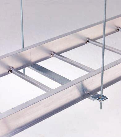
8 KwikSplice - Straight Sections KS4 and KS5 Straight Sections Straight Sections Straight Section Part Numbering Prefix Example: KS Series NEM lass Height Material Type Width Length KS = 50 Lbs/Ft 4 = 4 = luminum Ladder- 06 = 6" 144 = 12 ft. NEM 12 5 = 5 06 = 6" rung spacing 09 = 9" 120 = 10 ft. (12 ft. span) 09 = 9" rung spacing 12 = 12" rung spacing 12 = 12" 18 = 18" Primary Secondary Rung Spacing 24 = 24" Trough- 30 = 30" Width (Inside) Overall Width (Width /2 ) 04 = 4 rung spacing 36 = 36" SB = Solid Bottom Values are based on simple beam tests per VE-1 on 36" wide cable tray with rungs spaced on 12" centers. The published load safety factor is 1.5. To convert 1.5 safety factor to 2.0, multiply the published load by To obtain mid-span deflection, multiply a load by the deflection multiplier. able tray must be supported on spans shorter than or equal to the length of the tray. Ladder Type (Specify Rung Spacing) Solid Bottom 4 Rung Spacing Splices included with straight sections 4
9 KwikSplice - Straight Sections KS4 and KS5 Straight Section Technical Data B-Line Series NEM, S & UL Span Load Deflection Design Factors Span Load Deflection Design Factors Side Rail Dimensions lassifications ft lbs/ft Multiplier for Two Rails meters kg/m Multiplier for Two Rails Straight Sections KS NEM: rea = 0.80 in S: -3m Sx = 0.90 in UL ross-sectional Ix = 1.79 in rea: 0.60 in rea = 5.16 cm 2 Sx = cm 3 Ix = cm 4 B-Line Series NEM, S & UL Span Load Deflection Design Factors Span Load Deflection Design Factors Side Rail Dimensions lassifications ft lbs/ft Multiplier for Two Rails meters kg/m Multiplier for Two Rails KS NEM: rea = 0.92 in S: -3m Sx = 1.24 in UL ross-sectional Ix = 3.08 in rea: 0.60 in rea = 5.94 cm 2 Sx = cm 3 Ix = cm 4 When cable trays are used in continuous spans, the deflection of the cable tray is reduced by as much as 50%. Design factors: Ix = Moment of Inertia, Sx = Section Modulus. 5
10 KwikSplice - Straight Sections Straight Sections KSB4, KSB5, and KSB6 Straight Sections Straight Section Part Numbering Prefix Example: KS B Series NEM lass Height Material Type Width Length KS B = 75 Lbs/Ft 4 = 4 = luminum Ladder- 06 = 6" 144 = 12 ft. NEM 12B 5 = 5 06 = 6" rung spacing 09 = 9" 120 = 10 ft. (12 ft. span) 6 = 6 09 = 9" rung spacing 12 = 12" rung spacing 12 = 12" 18 = 18" Primary Secondary Rung Spacing 24 = 24" Trough- 30 = 30" Width (Inside) Overall Width (Width /2 ) 04 = 4 rung spacing 36 = 36" SB = Solid Bottom Values are based on simple beam tests per VE-1 on 36" wide cable tray with rungs spaced on 12" centers. The published load safety factor is 1.5. To convert 1.5 safety factor to 2.0, multiply the published load by To obtain mid-span deflection, multiply a load by the deflection multiplier. able tray must be supported on spans shorter than or equal to the length of the tray. Ladder Type (Specify Rung Spacing) Solid Bottom 4 Rung Spacing Splices included with straight sections 6
11 KwikSplice - Straight Sections KSB4, KSB5 and KSB6 Straight Section Technical Data B-Line Series NEM, S & UL Span Load Deflection Design Factors Span Load Deflection Design Factors Side Rail Dimensions lassifications ft lbs/ft Multiplier for Two Rails meters kg/m Multiplier for Two Rails Straight Sections KSB NEM: 12B S: D-3m UL ross-sectional rea: 0.60 in rea = 0.99 in rea = 6.39 cm Sx = 1.07 in Sx = cm Ix = 2.32 in Ix = cm 4 B-Line Series NEM, S & UL Span Load Deflection Design Factors Span Load Deflection Design Factors Side Rail Dimensions lassifications ft lbs/ft Multiplier for Two Rails meters kg/m Multiplier for Two Rails KSB NEM: 12B S: D-3m UL ross-sectional rea: 0.60 in rea = 1.12 in rea = 7.23 cm Sx = 1.47 in Sx = cm Ix = 3.96 in Ix = cm 4 B-Line Series NEM, S & UL Span Load Deflection Design Factors Span Load Deflection Design Factors Side Rail Dimensions lassifications ft lbs/ft Multiplier for Two Rails meters kg/m Multiplier for Two Rails KSB NEM: 12B S: D-3m UL ross-sectional rea: 1.00 in rea = 1.25 in rea = 8.06 cm Sx = 1.91 in Sx = cm Ix = 6.16 in Ix = cm 4 When cable trays are used in continuous spans, the deflection of the cable tray is reduced by as much as 50%. Design factors: Ix = Moment of Inertia, Sx = Section Modulus. 7
12 KwikSplice - ccessories Standard Splice Plates Furnished in pairs with 1 /4" hardware. UL lassified. One pair including hardware provided with each straight section. Tray Series KS_4 KS_5 KS_6 atalog No. KS4-SSP KS5-SSP KS6-SSP _ an be used with both NEM lass and B KwikSplice trays. Expansion Splice Plates Furnished in pairs with 1 /4" hardware. Bonding jumper required. Tray Series atalog No. ccessories KS_4 KS_5 KS_6 KS4-ESP KS5-ESP KS6-ESP Step Down Splice Plates Furnished in pairs with 1 /4" hardware. UL lassified. Tray Series KS_5 to KS_4 KS_6 to KS_4 KS_6 to KS_5 atalog No. KS-DSP-45 KS-DSP-46 KS-DSP-56 Vertical djustable Splice Plates Furnished in pairs with 1 /4" hardware. UL lassified. Requires supports within 24 on both sides, per NEM VE 2. Tray Series KS_4 KS_5 KS_6 atalog No. KS4-VSP KS5-VSP KS6-VSP Horiztonal djustable Splice Plates Furnished in pairs with 1 /4" hardware. Horizontally adjustable to 90. Vertically adjustable to 15. UL lassified. For optional rung, see page 18. Requires supports within 24 on both sides, per NEM VE 2. Tray To Box Splice Plates Furnished in pairs with 1 /4" hardware. UL lassified. Tray Series KS_4 KS_5 KS_6 Tray Series KS_4 KS_5 KS_6 atalog No. KS4-FSP KS5-FSP KS6-FSP atalog No. KS4-TTB KS5-TTB KS6-TTB 8
 3, 6, 9, 12, 15, 18, 21, 24, 27, or 30 Bonding Jumper Furnished with 1 /4\" hardware. UL lassified.")

13 KwikSplice - ccessories Offset Reducing Splice Plates Furnished in pairs with 1 /4" hardware. UL lassified. Specify the following: = center reducer S = side reducer r (tray reduction) 3, 6, 9, 12, 15, 18, 21, 24, 27, or 30 Bonding Jumper Furnished with 1 /4" hardware. UL lassified. Right (or Left) Reducer enter Reducer Tray Series KS_4 KS_5 KS_6 atalog No. KS4-RSP- r KS5-RSP- r KS6-RSP- r _ an be used with both NEM lass and B KwikSplice trays. mpacity atalog No ccessories Grounding lamp ccepts #6 WG to 250 MM. UL lassified as to its suitability as an equipment grounding conductor. Material atalog No. Tin Plated luminum onduit to Tray daptors onduit Size in. (mm) atalog No. 1 /2, 3 /4 (15, 20) 9G /2, 3 /4 1, 1 1 /4 (25, 32) 9G , 1 1 /4 1 1 /2, 2 (40, 50) 9G /2, /2, 3 (65, 80) 9G /2, /2, 4 (90, 100) 9G /2, 4 Guide-Rite onduit to Tray daptor ssemblies support 1 /2", 3 /4", & 1 conduit. ttaches to top or bottom of I-Beam side rail flange. onduit Size in. (mm) atalog No. Patent # Lbs. Static Load apacity 1 /2, 3 /4 (15, 20) BG-8-12-W2 1 (25) BG-16-W2 Vertical onduit Hanger dapter Furnished as one plate with fastener attachments. Utilizes (2) BX-4-16 Under Rung Fastener ttachments. ccepts 1 /2 to 4 conduit. onduit Size atalog No. in. (mm) 1 /2 (15) KS-VH- 1 /2 3 /4 (20) KS-VH- 3 /4 1 (25) KS-VH /4 (32) KS-VH-1 1 /4 1 1 /2 (40) KS-VH-1 1 /2 2 (50) KS-VH-2 3 (75) KS-VH-3 4 (100) KS-VH-4 9
14 KwikSplice - ccessories Drop-Out Snaps on to cable tray rung. Provides 4 (101mm) radius. Holes provided to secure cables. atalog No. KS-OUT- = Insert tray width ccessories Side Rail Drop-Out Snaps on to cable tray side rail. Provides 4 (101mm) radius. Holes provided to secure cables. atalog No. Length in. (mm) KS-SDO-06 6 (152) KS-SDO (305) KS-SDO (457) lamp/guide Features a no-twist design. Each side is labeled to ensure proper installation. Designed for 1 /4 hardware. Furnished in pairs with or without hardware. Patent No. RE (38mm) atalog No. 9ZN-1204 (without hardware) 9ZN-1204NB (with hardware) Frame Type Box onnector Furnished with 1 /4" hardware for tray connection. Tray Series KS_4 KS_5 KS_6 atalog No. KS4-FTB- KS5-FTB- KS6-FTB- = tray width Blind End Furnished as one plate with 1 /4" hardware. Tray Series KS_4 KS_5 KS_6 = tray width atalog No. KS4-END- KS5-END- KS6-END- _ an be used with both NEM lass and B Kwik Splice trays. 10
15 KwikSplice - ccessories Tab & Lock Trapeze Support Hardware purchased separately. ccepts up to 3 /8 rod. ccepts traditional hold down clamps (9ZN-1204) if necessary. bility to adjust tabs with flat head screw driver (not included). Tabs clamp cable tray to trapeze support. Load capacity: Rated for maximum load of KwikSplice cable tray system. orrosion resistant pre-galvanized zinc finish. Other finishes available upon request. Trapeze Support Only Trapeze Support Shown With Buzznut Hardware Hardware Qty. atalog No Standard (4) B201 (4) 3/8 HN or Buzznut (4) SLWN3/8 Standard Hardware Buzznut Hardware atalog No. Tray Width in. (mm) KS-6T 6 (152) KS-9T 9 (229) KS-12T 12 (305) KS-18T 18 (457) KS-24T 24 (610) KS-30T 30 (762) KS-36T 36 (914) ccessories Trapeze Support Kit B-Line trapeze kits provide the components required for a single trapeze support in one package. These kits are available in pregalvanized steel with zinc-plated hardware or hot dip galvanized steel with 316 stainless steel hardware. The SH channel provides the convenience of pre-punched slots, which eliminate the need for field drilling. The illustrated hardware is sealed in a plastic bag and boxed with the channel, which is pre-cut to the appropriate length as shown in the chart. Designed for use with 1 /2" threaded rod. Order rod separately. (2) 1/2" x 7/8" Hex Head ap Screw (2) 9ZN-1205 Hold-Down Guide lamp (2) N525WO hannel Nut (4) 1/2" Hex Nut (4) B202 Square Washer (1) B22 hannel cut to the required length atalog Tray hannel Uniform No. Width Length Load in. (mm) in. (mm) lbs (kn) 9P SH( ) 6 (152) 16 (406) 1600 (7.11) 9P SH( ) 9 (229) 18 (457) 1250 (5.56) 9P SH( ) 12 (305) 22 (559) 1125 (5.00) 9P SH( ) 18 (457) 28 (711) 865 (3.85) 9P SH( ) 24 (610) 34 (864) 700 (3.11) 9P SH( ) 30 (762) 40 (1016) 590 (2.62) 9P SH( ) 36 (914) 46 (1168) 510 (2.27) ( ) Insert 3 /8 for 3 /8" threaded rod hardware. Safety factor of 3.0 on all loads. Trapeze Hardware Kit atalog No. 9ZN /2 9G /2 In plastic bag 1 pr. 9ZN pr. 9G HH Screw 1 /2 x 7 /8 ZN 2 HH Screw 1 /2 x 7 /8 SS6 2 N525 WO ZN 2 N525 WO SS6 4 B202 ZN 1 /2" sq washer 4 B202 HDG 1 /2" sq washer 4 HN 1 /2 ZN 4 HN 1 /2 SS6 11
16 KwikSplice - ccessories Bracket (12-24 ) Finishes available: ZN, GRN, or HDG Safety Load Factor 2.5 atalog Uniform Load Tray Width '' No. lbs (kn) in. (mm) in. (mm) B (7.02) 6 & 9 (152 & 229) 12 (305) B (4.45) 12 (305) 18 (457) B (4.43) 18 (457) 24 (610) ccessories Bracket (30-42 ) Finishes available: ZN, GRN, or HDG Safety Load Factor 2.5 atalog Uniform Load Tray Width '' No. lbs (kn) in. (mm) in. (mm) B (4.11) 24 (610) 30 (762) B (3.84) 30 (762) 36 (914) B (2.58) 36 (914) 42 (1067) antilever Bracket (12-24 ) Finishes available: ZN, GRN, HDG, SS4 or SS6 Safety Load Factor 2.5 atalog Uniform Load Tray Width '' No. lbs (kn) in. (mm) in. (mm) B (4.27) 6 & 9 (152 & 229) 12 (305) B (2.84) 12 (305) 18 (457) B (2.13) 18 (457) 24 (610) antilever Bracket (12-42 ) Finishes available: ZN, GRN, HDG, or SS4 Safety Load Factor 2.5 atalog Uniform Load Tray Width '' No. lbs (kn) in. (mm) in. (mm) B (7.38) 6 & 9 (152 & 229) 12 (305) B (4.89) 12 (305) 18 (457) B (3.71) 18 (457) 24 (610) B (2.95) 24 (610) 30 (762) B (2.44) 30 (762) 36 (914) B (2.06) 36 (914) 42 (1067) 12
 B501-1 1 /4 1.316-1.660 (33-42) B501-1 1 /2 1.661-1.900 (42-48) B501-2 1.901-2.375 (48-60) B501-2 1 /2 2.376-2.")
 Insert ZN, SS4, or SS6 atalog No. Uniform Load Tray Width '' lbs (kn) in. (mm) in.")
17 KwikSplice - ccessories Underfloor Support (U-Bolts not included) Finish available: ZN Safety Load Factor 2.5 U-Bolt Size Fits Pipe O.D. in. (mm) B501-3 / (21-26) B (27-33) B / (33-42) B / (42-48) B (48-60) B / (60-73) Order 2 properly sized U-Bolts (sold separately) for each underfloor support. Heavy Duty Hold Down Bracket Design load is 2000 lbs/pair. Two bolt design. Sold in pairs. 3 /8" cable tray attachment hardware provided. 1 /2" support attachment hardware not provided. (*) Insert ZN, SS4, or SS6 atalog No. Uniform Load Tray Width '' lbs (kn) in. (mm) in. (mm) B409UF (3.55) 6 & 9 (152 & 229) 12 (305) B409UF (2.00) 12 & 18 (305 & 457) 21 (533) ccessories atalog No. 9(*)-1241 Under Rung Fastener ttachment Supports electrical fixtures from bottom of rung or siderails. Wing nut included. Various 1 /4"-20 stud lengths available. Static Load apacity: 75 Lbs. (34kg). Stud atalog No. Length in. (mm) BX /8 (16) BX /2 (38) BX (51) BX (76) DUR-BLOK Support Bases with B22 hannel atalog No. Height x Width x Length Designed as a superior rooftop support for cable tray, UV resistant and approved for most roofing material or other flat surfaces. an be used with any of B-Line cable tray clamps and guides. Ultimate Load apacity: 1,000 lbs. (uniform load) LEEDS credit available, base made from 100% recycled material. in. (mm) DB /8 x 6 x 28 (143 x 152 x 711) DB /8 x 6 x 36 (143 x 152 x 914) DB /8 x 6 x 42 (143 x 152 x 1067) DB /8 x 6 x 50 (143 x 152 x 1270) DB /8 x 6 x 60 (143 x 152 x 1524) General Note: onsult roofing manufacturer or engineer for roof load capacity. The weakest point may be the insulation board beneath the rubber membrane. 13
18 KwikSplice - ccessories overs for KS4, KS5, KSB4, KSB5, and KSB6 Solid Non-Flanged Solid Flanged Ventilated Flanged ccessories full range of covers are available for straight sections and fittings. Solid covers should be used when maximum enclosure of the cable is desired and no accumulation of heat is expected. Ventilated covers provide cable protection, while allowing heat to escape. Flanged covers have a 1 /2 in. (13 mm) flange. over clamps are not included with the cover and must be ordered separately. B-Line recommends that covers be placed on vertical cable tray runs to a height of 6 ft. (1.83 m) to 8 ft. (2.44 m) above the floor to isolate both cables and protect personnel. luminum over Part Numbering Prefix Example: over Type Detail Material Tray Width Item Description 80 = Solid 6 = Non-Flanged = luminum 06 = 6" For Straight Section over: 81 = Ventilated (80 & 81 type only) 7 = Flange 09 = 9" 144 = 12 ft. (3.66 m) 12 = 12" 120 = 10 ft. (3.05 m) 18 = 18" 72 = 6 ft. (1.83 m) 24 = 24" 60 = 5 ft. (1.52 m) 30 = 30" For fitting covers: Insert suffix of 36 = 36" fitting to be covered. See example below. Examples of atalog Numbers for Fitting overs: Horizontal Bend over Prefix Suffix HB 24 Radius Fitting ngle Width Material Detail over Type Prefix Vertical Bend over Suffix VO 24-4* Side Rail* Height Radius Fitting ngle Width Material Detail over Type * Required for VO fittings only 14


19 KwikSplice - ccessories Standard over lamp For indoor service only. Setscrew included. Sold per piece. Tray Side Rail Type Height atalog No. KS Series ll Sizes 9ZN Heavy Duty over lamp Recommended for outdoor service. Side Rail atalog Height No. in. (mm) KS4-HD-( ) KS5-HD-( ) KS6-HD-( ) ccessories ( ) Insert tray width Quantity of Standard over lamps Required Straight Section 60" or 72"...4 pcs. Straight Section 120" or 144"...6 pcs. Horizontal/Vertical Bends...4 pcs. Tees...6 pcs. rosses...8 pcs. Note: When using the Heavy Duty over lamp, only one-half the number of clamps stated above is required. over Joint Strip Used to join covers Plastic ( ) Insert tray width atalog No ( ) able leats (see able Tray Systems catalog) Trefoil able leats Single able leats 15
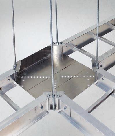
20 KwikSplice - ccessories Universal Fitting luminum construction. 2" smooth radius. UL lassified. Shipped as a 90 horizontal bend. Field modify to create a tee or cross. Includes four pairs of toolless hinge splice plates. Patent Pending. Solid Bottom ccessories Punched Bottom Tray atalog No. Series Punched Solid KS_4 KS4-UF-( ) KS4SB-UF-( ) KS_5 KS5-UF-( ) KS5SB-UF-( ) KS_6 KS6-UF-( ) KS6SB-UF-( ) ( ) Insert Tray Width 6" (152mm) to 36 (914mm) orner Post For Universal Fitting Use to create reducing fittings. Furnished with hardware. 2" inside radius. Used on punched bottom only. UL lassified. Patent Pending. Universal Fitting Shown as a Reducing Tee Tray Series KS_4 KS_5 KS_6 = tray width atalog No. KS4-P KS5-P KS6-P Barrier Strip lip Provides attachment to KwikSplice rung. llows for installed barrier adjustment. symmetrical clip provides a wide range for screw location. Barriers strip clips and hardware are included with all barriers. Barrier Flange Rung Screw slot for sheet metal screw atalog No. 9-RB 16
21 KwikSplice - ccessories Straight Section Barrier Strip Furnished with four (4) barrier strip clips, mounting hardware and splice. Standard lengths are 144" (12 ft) & 120" (10 ft). Order catalog number based on loading depth H. Tray H Series atalog No. in. (mm) KS_4 R4-DSL-Length 3 (76) KS_5 R5-DSL-Length 4 (101) Horizontal Bend Barrier Strip Furnished with three (3) barrier strip clips, mounting hardware and splice. Standard length is 72" (6 ft). Flexible to fit desired angles. Order catalog number based on loading depth H. H KS_6 R6-DSL-Length 5 (127) ccessories Tray H Series atalog No. in. (mm) KS_4 R4-DHB 3 (76) KS_5 R5-DHB 4 (101) KS_6 R6-DHB 5 (127) H Vertical Bend Barrier Strip Furnished with three (3) barrier strip clips, mounting hardware and splice. Inside Bend (VI) H H Outside Bend (VO) Tray atalog No. H Series Inside Bend Outside Bend in. (mm) KS_4 R4-DVI-(**)R( ) R4-DVO-(**)R( ) 3 (76) KS_5 R5-DVI-(**)R( ) R5-DVO-(**)R( ) 4 (101) KS_6 R6-DVI-(**)R( ) R6-DVO-(**)R( ) 5 (127) (**) Insert 30, 45, 60, 90 for angles ( ) Insert 12, 24 for radius 17
22 KwikSplice - ccessories How to miter cut KwikSplice cable tray for use with Horizontal djustable splice plates. ut location ount over number of inches specified in chart ount over number of inches specified in chart ut location ccessories KS Straight Section shown with required side rail removed to form 90 fitting. Example: For a 12" wide 90 bend, the cuts must be made 12 5 /8 (320.7mm) from the end. Mark desired hole/cut locations per chart. Remove any rungs (if necessary) affected by cuts. ut side rails through center of required holes per chart. Mount outside Horizontal djustable splice plate with provided hardware and bend Kwik Splice sections to desired angle. Form inside Horizontal djustable splice plate to fit contour of inner rails and bolt into place. Reinstall (if necessary) appropriate rungs. Torque to 18 ft lbs. If Splice Rung Kit (see below) is required, order separately. Recommend adding one to the value in the chart if the first hole is less than 3 /8" from the end of tray. ut Length from Rail End For Tray Desired ngle Width in. (mm) in. (mm) in. (mm) in. (mm) in. (mm) 6 (152) 1 5 /8 (41.3) 3 1 /8 (79.4) 3 1 /8 (79.4) 6 1 /4 (158.7) 9 (228) 3 1 /8 (79.4) 3 1 /8 (79.4) 4 3 /4 (120.6) 9 3 /8 (238.2) 12 (305) 3 1 /8 (79.4) 4 3 /4 (120.6) 6 1 /4 (158.7) 12 5 /8 (320.7) 18 (457) 4 3 /4 (120.6) 7 7 /8 (200.0) 11 (279.4) 17 1 /4 (438.1) 24 (609) 6 1 /4 (158.7) 9 3 /8 (238.2) 14 1 /8 (358.8) 23 5 /8 (600.1) 30 (762) 7 7 /8 (200.0) 12 5 /8 (320.7) 17 1 /4 (438.1) 29 7 /8 (758.8) 36 (914) 9 3 /8 (238.2) 15 3 /4 (400.0) 20 3 /8 (517.5) 36 1 /8 (917.6) Horizontal djustable Splice Rung Kit Kit allows a support rung to be added to Horizontal djustable splice plates so that cables may be supported through a bend. The support rung is available in three lengths and should be ordered based upon tray width. The rung length is sized so that it will fit a maximum tray width when Horizontal djustable splices are used to make a bend up to 90. Once the Horizontal djustable splices are installed in the cable tray system, the distance between the splice mounting surfaces should be measured. ut support rung to the measured distance and install using the hardware included. Torque to 18 ft lbs. Example: Flex connectors are installed on an 18" (457mm) wide tray with approximately a 45 bend. The correct support rung kit is 9-RFM-24RK. The tray width is 24" or less and the angle is less than 90. For Tray ctual Width atalog No. Rung Length in. (mm) in. (mm) 6, 9, 12 (152, 228, 305) 9-RFM-12RK 20 (508) 18, 24 (457, 609) 9-RFM-24RK 37 (940) 30, 36 (762, 914) 9-RFM-36RK 54 (1371) 18
23 KwikSplice - ccessories Data ables The National Electrical ode allows for 50% fill of ventilated cable tray for control or signal wiring (rticle 392-9(b)). This rule requires that all the individual cable cross-sectional areas added up may not exceed one half the cable tray area. The cable tray area is equal to the width times the load depth. In actual practice with data cables, however, the cable tray becomes completely full in reaching the "50% cable fill". The tray is completely full, but the sum of the cable areas is only 50% of the tray area, due to the empty spaces between the cables. Data able Fill and Weight hart Number of ategory 5/5e/6 ables and alculated able Weight in Lbs/Ft ccessories Tray Depth Tray Width 6" 9" 12" 18" 24" 30" 36" in mm ables lbs/ft ables lbs/ft ables lbs/ft ables lbs/ft ables lbs/ft ables lbs/ft ables lbs/ft This chart was based on 50% fill of 4 UTP ategory 5, 5e, or 6 cables (O.D. =.21".026 lbs/ft). In the above loading grid, the weight of the cables is not the issue. The volume capacity of the tray governs. For example, the worst case (6" load depth, 36" wide) has a total cable weight of 81 lbs/ft. 19
24 KwikSplice - Specifications Section 161xx - KwikSplice able Tray Specification PRT 1 GENERL 1.1 Summary. The work covered under this section consists of the furnishing of all necessary labor, supervision, materials, equipment, tests and services to install complete cable tray systems as shown on the drawings. B. able tray systems are defined to include, but are not limited to straight sections of cable trays, fittings, drop-outs, supports and accessories. 1.2 References. NEM VE Metal able Tray Systems. B. NEM VE able Tray Installation Guidelines.. NSI/NFP 70 National Electrical ode 1.3 Drawings. The drawings, which constitute a part of these specifications, indicate the general route of the cable runway systems. Data presented on these drawings is as accurate as preliminary surveys and planning can determine until final equipment selection is made. ccuracy is not guaranteed and field verification of all dimensions, routing, etc., is required. B. Specifications and drawings are for assistance and guidance, but exact routing, locations, distances and levels will be governed by actual field conditions. ontractor is directed to make field surveys as part of his work prior to submitting system layout drawings. 1.4 Quality ssurance. Manufacturers: Firms regularly engaged in manufacture of cable trays and fittings of types and capacities required, whose products have been in satisfactory use in similar service for not less than 10 years. B. NEM ompliance: omply with NEM Standards Publication Number VE1, "able Tray Systems".. NE ompliance: omply with NE, as applicable to construction and installation of cable tray and cable channel systems (rticle 392, NE). D. UL ompliance: Provide products that are UL-classified and labeled. E. NFP ompliance: omply with NFP 70B, "Recommended Practice for Electrical Equipment Maintenance" pertaining to installation of cable tray systems. 1.5 Delivery, Storage and Handling. Deliver cable tray systems and components carefully to avoid breakage, denting and scoring finishes. Do not install damaged equipment. B. Store cable trays and accessories in original cartons and in clean dry space; protect from weather and construction traffic. Wet materials should be unpacked and dried before storage. 1.6 Submittals. Shop Drawings: Indicate tray type, dimensions, support points, and finishes. B. Product Data: Submit fittings and accessories.. Manufacturer's Installation Instructions: Submit application conditions and limitations of use stipulated by Product testing agency specified under Regulatory Requirements. Include instructions for storage, handling, protection, examination, preparation, and installation of Product. PRT 2 PRODUTS 2.1 cceptable Manufacturers. Manufacturer: Subject to compliance with these specifications, cable tray systems shall be as manufactured by Eaton s B-Line Business (formerly ooper B-Line, Inc.). 2.2 able Tray Sections and omponents. General: Except as otherwise indicated, provide metal cable trays, of types, classes, and sizes indicated; with splice plates, bolts, nuts and washers for connecting units. onstruct units with rounded edges and smooth surfaces; in compliance with applicable standards; and with the following additional construction features. able tray shall be installed according to the latest revision of NEM VE-2. B. Material and Finish: Straight section, fitting side rails, rungs and splice plates shall be extruded from luminum ssociation lloy ll fabricated parts shall be made from luminum ssociation lloy Type of Tray System. Ladder able Trays shall consist of two longitudinal members (side rails) with transverse members (rungs) welded to both side rails. Both side rails and rungs shall be I-beam configuration. Side rails shall have a splice retention groove to accept a splice plate. Rungs shall be spaced [4] [6] [9] [12] inches on center. Rung spacing in radiused fittings shall be industry standard 9 and measured at the center of the tray s width. (continued on page 21) 20
25 KwikSplice - Specifications (continued from page 20) B. Ventilated Bottom able Trays shall consist of two longitudinal members (side rails) with rungs spaced 4 on center.. Solid Bottom able Trays shall consist of two longitudinal members (side rails) with a solid sheet over rungs spaced on 12 centers. D. able tray loading depth shall be [3] [4] [5] inches per NEM VE-1. E. Straight sections shall be supplied in standard [10 foot (3.05m)] [12 foot (3.65m)] lengths. F. able tray widths shall be [6] [9] [12] [18] [24] [30] [36] inches or as shown on drawings. G. Splice plates shall have a maximum of (2) two nuts and bolts per plate. The resistance of fixed splice connections between adjacent sections of tray shall not exceed ohms. Splice plates shall be furnished with straight sections and fittings. ll horizontal fittings (horizontal bend, horizontal tee, horizontal cross) to be installed utilizing B-Line Kwik Splice Universal Fitting. ll vertical fittings must have a minimum radius of [12] [24] inches. ****** [OR] ****** ll fittings must have a minimum radius of [12] [24] inches. 2.4 Loading apacities. able trays shall meet NEM class designation: {NEM 12: [50 lbs./ft. on a 12 ft. span]} OR {NEM 12B: [75 lbs./ft. on a 12 ft. span]}. ****** [OR] ****** B. able tray shall be capable of carrying a uniformly distributed load of lbs./ft on a foot support span with a safety factor of 1.5 when supported as a simple span and tested per NEM VE 1 Section ccessories. overs: 1. Furnish only where indicated on the Drawings. 2. Solid or ventilated as indicated. 3. Same manufacturer and material as the tray. 4. Secure covers with manufacturer s approved clamps. 5. lamp spacing per manufacturer s recommendations. B. Dividers: 1. Manufactured by the cable tray manufacturer of the same material as the tray.. Mounting hardware: 1. Zinc coated tray bolts, nuts, and fasteners: quantity not to exceed two each per splice plate. D. Trapeze Supports 1. Manufactured by the cable tray manufacturer. E. able Exit Options 1. Radiused drop outs must be utilized for cables exiting the cable tray through the rungs or over either side rail ****** [OR] ****** 2. onduit connectors must be utilized to securely connect the conduit runs to the cable tray when a cable exits through the rungs or over either side rail. Specification PRT 3 EXEUTION 3.1 Installation. Install cable trays as indicated: Installation shall be in accordance with equipment manufacturer's instructions, and with recognized industry practices to ensure that cable tray equipment comply with requirements of NE and applicable portions of NFP 70B. Reference NEM-VE2 for general cable tray installation guidelines. B. oordinate cable tray with other electrical work as necessary to properly integrate installation of cable tray work with other work.. Provide sufficient space encompassing cable trays to permit access for installing and maintaining cables. D. able tray fitting supports shall be located such that they meet the strength requirements of straight sections. Install fitting supports per NEM VE-2 guidelines, or in accordance with manufacturer's instructions. 3.2 Testing. Test cable trays to ensure electrical continuity of bonding and grounding connections, and to demonstrate compliance with specified maximum grounding resistance. See NFP 70B, hapter 18, for testing and test methods. B. Manufacturer shall provide test reports witnessed by an independent testing laboratory of the "worst case" loading conditions outlined in this specification and performed in accordance with the latest revision of NEM VE-1/S 22.2 No END OF SETION 21

26 KwikSplice - Fittings Fittings For KS4, KS5, KSB4, KSB5 and KSB6 Fittings engineered with 3 tangents for splicing integrity. Fitting Part Numbering Prefix Example: KS HB 24 Series Height Material Type Width ngle* Fitting Type Radius KS = 4 = 4 = luminum Ladder 06 = 6" 30 = 30 *HB = Horizontal Bend 12 = 12 KwikSplice 5 = 5 09 = 09 = 9" 45 = 45 HT = Horizontal Tee 24 = 24 6 = 6 9" rung spacing 12 = 12" 60 = 60 HX = Horizontal ross 18 = 18" 90 = 90 *VI = Vertical Inside Bend Other 24 = 24" *VO = Vertical Outside Bend 04 = 30 = 30" VT = Vertical Tee, Down 4 rung spacing 36 = 36" VTU = Vertical Tee, Up SB = Solid Bottom LR = Left Reducer RR = Right Reducer SR = Straight Reducer Fittings Expanding & Reducing Horizontal Tee & ross Fitting Part Numbering Prefix Example: KS HT 24 Series Height Material Type Width 1 Width 2 Fitting Type Radius KS = 4 = 4 = luminum Ladder 06 = 6" 06 = 6" HT = Horizontal Tee 12 = 12 KwikSplice 5 = 5 09 = 09 = 9" 09 = 9" (Reducing - where Width 1 24 = 24 6 = 6 9" rung spacing 12 = 12" 12 = 12" is larger than Width 2) 18 = 18" 18 = 18" (Expanding - where Width 1 Other 24 = 24" 24 = 24" is smaller than Width 2) 04 = 30 = 30" 30 = 30" 4 rung spacing 36 = 36" 36 = 36" HX = Horizontal ross SB = (Reducing/Expanding - where Width 1 Solid Bottom is larger than Width 2) For ventilated or solid bottom, add 04 or SB as shown below: vailable 6" thru 36" Prefix Prefix KS HB24 KS5SB HB24 4 Rung Spacing Bottom Solid Bottom 22
27 KwikSplice - Fittings Horizontal Bend (HB) 1 pair splice plates with hardware included. 90 Horizontal Bend 90 HB 60 Horizontal Bend 60 HB Bottoms manufactured: Ladder = 9" Rung Spacing 04 = 4" Rung Spacing SB = Flat sheet over 9" Rung Spacing B R 3" (76) B R 3" (76) Bend Tray 90 Horizontal Bend 60 Horizontal Bend Radius Width Dimensions Dimensions R atalog No. B atalog No. B in. (mm) in. (mm) in. (mm) in. (mm) in. (mm) in. (mm) in. (mm) in. (mm) 12 (305) 24 (610) 6 (152) (Pre)-06-90HB12 18 (457) 18 (457) 18 (457) (Pre)-06-60HB /2 (445) 10 1 /8 (257) /16 (297) 9 (228) (Pre)-09-90HB /2 (495) 19 1 /2 (495) 19 1 /2 (495) (Pre)-09-60HB /16 (478) 10 7 /8 (276) 12 1 /2 (318) 12 (305) (Pre)-12-90HB12 21 (533) 21 (533) 21 (533) (Pre)-12-60HB /16 (510) 11 5 /8 (295) 13 3 /8 (340) 18 (457) (Pre)-18-90HB12 24 (610) 24 (610) 24 (610) (Pre)-18-60HB /16 (576) 13 1 /8 (333) 15 1 /8 (384) 24 (609) (Pre)-24-90HB12 27 (686) 27 (686) 27 (686) (Pre)-24-60HB /16 (643) 14 5 /8 (372) 16 7 /8 (429) 30 (762) (Pre)-30-90HB12 30 (762) 30 (762) 30 (762) (Pre)-30-60HB /8 (708) 16 1 /8 (410) 18 9 /16 (472) 36 (914) (Pre)-36-90HB12 33 (838) 33 (838) 33 (838) (Pre)-36-60HB /2 (775) 17 5 /8 (448) 20 5 /16 (516) 6 (152) (Pre)-06-90HB24 30 (762) 30 (762) 30 (762) (Pre)-06-60HB /8 (708) 16 1 /8 (410) 18 9 /16 (472) 9 (228) (Pre)-09-90HB /2 (800) 31 1 /2 (800) 31 1 /2 (800) (Pre)-09-60HB /16 (741) 16 7 /8 (429) 19 7 /16 (494) 12 (305) (Pre)-12-90HB24 33 (838) 33 (838) 33 (838) (Pre)-12-60HB /2 (775) 17 5 /8 (448) 20 5 /16 (516) 18 (457) (Pre)-18-90HB24 36 (914) 36 (914) 36 (914) (Pre)-18-60HB /16 (708) 19 1 /8 (486) 22 1 /16 (560) 24 (609) (Pre)-24-90HB24 39 (991) 39 (991) 39 (991) (Pre)-24-60HB /16 (907) 20 5 /8 (524) /16 (605) 30 (762) (Pre)-30-90HB24 42 (1067) 42 (1067) 42 (1067) (Pre)-30-60HB /4 (972) 22 1 /8 (564) 25 1 /2 (648) 36 (914) (Pre)-36-90HB24 45 (1143) 45 (1143) 45 (1143) (Pre)-36-60HB /8 (1038) 23 5 /8 (600) 27 1 /4 (692) Fittings (Pre) See page 22 for catalog number prefix. Width dimensions are to inside wall. For aluminum fittings add 1.5 inches for total outside width. Manufacturing tolerances apply to all dimensions. ll dimensions in parentheses are in millimeters unless otherwise specified. 23
28 KwikSplice - Fittings Horizontal Bend (HB) 1 pair splice plates with hardware included. Bottoms manufactured: Ladder = 9" Rung Spacing 04 = 4" Rung Spacing SB = Flat sheet over 9" Rung Spacing 45 Horizontal Bend 30 Horizontal Bend B 45 HB B 30 HB R 3" (76) R 3" (76) Bend Tray 45 Horizontal Bend 30 Horizontal Bend Radius Width Dimensions Dimensions R atalog No. B atalog No. B in. (mm) in. (mm) in. (mm) in. (mm) in. (mm) in. (mm) in. (mm) in. (mm) Fittings 12 (305) 24 (610) 6 (152) (Pre)-06-45HB /4 (400) 6 1 /2 (165) 9 3 /16 (233) (Pre)-06-30HB /8 (333) 3 1 /2 (89) 7 (179) 9 (228) (Pre)-09-45HB /16 (427) 6 15 /16 (176) 9 13 /16 (249) (Pre)-09-30HB /8 (352) 3 11 /16 (94) 7 7 /16 (189) 12 (305) (Pre)-12-45HB /8 (454) 7 3 /8 (187) 10 7 /16 (265) (Pre)-12-30HB /8 (372) 3 15 /16 (100) 7 13 /16 (198) 18 (457) (Pre)-18-45HB12 20 (508) 8 1 /4 (210) /16 (297) (Pre)-18-30HB /8 (410) 4 5 /16 (135) 8 5 /8 (219) 24 (609) (Pre)-24-45HB /16 (560) 9 1 /8 (232) /16 (329) (Pre)-24-30HB /8 (448) 4 11 /16 (119) 9 7 /16 (240) 30 (762) (Pre)-30-45HB /16 (614) 10 (254) 14 3 /16 (360) (Pre)-30-30HB /8 (486) 5 1 /8 (130) 10 1 /4 (260) 36 (914) (Pre)-36-45HB /16 (668) /16 (278) 15 7 /16 (392) (Pre)-36-30HB /8 (524) 5 1 /2 (140) 11 1/ 16 (281) 6 (152) (Pre)-06-45HB /16 (614) 10 (254) 14 3 /16 (360) (Pre)-06-30HB /8 (486) 5 1 /8 (130) 10/4 (260) 9 (228) (Pre)-09-45HB /4 (641) 10 1 /2 (267) /16 (376) (Pre)-09-30HB /8 (505) 5 5 /16 (135) 10 5 /8 (270) 12 (305) (Pre)-12-45HB /16 (668) /16 (278) 15 7 /16 (392) (Pre)-12-30HB /8 (524) 5 1 /2 (140) 11 1 /16 (281) 18 (457) (Pre)-18-45HB /16 (722) /16 (300) /16 (424) (Pre)-18-30HB /8 (562) 5 15 /16 (151) /16 (300) 24 (609) (Pre)-24-45HB /16 (766) /16 (322) /16 (456) (Pre)-24-30HB /8 (600) 6 5 /16 (160) 12 5 /8 (321) 30 (762) (Pre)-30-45HB /16 (830) 13 9 /16 (344) 19 1 /8 (486) (Pre)-30-30HB /8 (638) 6 3 /4 (172) 13 7 /16 (341) 36 (914) (Pre)-36-45HB /16 (884) 14 7 /16 (367) 20 3 /8 (518) (Pre)-36-30HB /8 (676) 7 1 /8 (181) 14 1 /4 (362) (Pre) See page 22 for catalog number prefix. Width dimensions are to inside wall. For aluminum fittings add 1.5 inches for total outside width. Manufacturing tolerances apply to all dimensions. ll dimensions in parentheses are in millimeters unless otherwise specified. 24
29 KwikSplice - Fittings Horizontal Tee (HT) Horizontal ross (HX) 2 pair splice plates with hardware included. 3 pair splice plates with hardware included. B HT B HX W R 3" (76) R 3" (76) W Bend Tray Horizontal Tee Horizontal ross Radius Width Dimensions Dimensions R atalog Number B atalog Number B in. (mm) in. (mm) in. (mm) in. (mm) in. (mm) in. (mm) 6 (152) (Prefix)-06-HT12 18 (457) 36 (914) (Prefix)-06-HX12 18 (457) 36 (914) 9 (229) (Prefix)-09-HT /2 (496) 39 (991) (Prefix)-09-HX /2 (496) 39 (991) 12 (305) (Prefix)-12-HT12 21 (533) 42 (1067) (Prefix)-12-HX12 21 (533) 42 (1067) 12 (305) 18 (457) (Prefix)-18-HT12 24 (609) 48 (1219) (Prefix)-18-HX12 24 (609) 48 (1219) 24 (609) (Prefix)-24-HT12 27 (686) 54 (1372) (Prefix)-24-HX12 27 (686) 54 (1372) 30 (762) (Prefix)-30-HT12 30 (762) 60 (1524) (Prefix)-30-HX12 30 (762) 60 (1524) 36 (914) (Prefix)-36-HT12 33 (838) 66 (1676) (Prefix)-36-HX12 33 (838) 66 (1676) 6 (152) (Prefix)-06-HT24 30 (762) 60 (1542) (Prefix)-06-HX24 30 (762) 60 (1524) 9 (229) (Prefix)-09-HT /2 (800) 63 (1600) (Prefix)-09-HX /2 (800) 63 (1600) 12 (305) (Prefix)-12-HT24 33 (838) 66 (1676) (Prefix)-12-HX24 33 (838) 66 (1676) 24 (610) 18 (457) (Prefix)-18-HT24 36 (914) 72 (1828) (Prefix)-18-HX24 36 (914) 72 (1828) 24 (609) (Prefix)-24-HT24 39 (991) 78 (1982) (Prefix)-24-HX24 39 (991) 78 (1982) 30 (762) (Prefix)-30-HT24 42 (1067) 84 (2134) (Prefix)-30-HX24 42 (1067) 84 (2134) 36 (914) (Prefix)-36-HT24 45 (1143) 90 (2286) (Prefix)-36-HX24 45 (1143) 90 (2286) Fittings (Prefix) See page 22 for catalog number prefix. Width dimensions are to inside wall. For aluminum fittings add 1.5 inches for total outside width. Manufacturing tolerances apply to all dimensions. ll dimensions in parentheses are millimeters unless otherwise specified. 25
30 KwikSplice - Fittings Reducers (LR, SR, RR) 1 pair splice plates with hardware included. Reducer Part Numbering Prefix RR 18 Width 2 Fitting Width 1 Prefix Left Reducer W 2 LR Straight Reducer W 2 SR Right Reducer W 2 RR W 1 W 1 W 1 Tray Width Left Reducer - LR Straight Reducer - SR Right Reducer - RR W 1 W 2 atalog No. atalog No. atalog No. in. (mm) in. (mm) in. (mm) in. (mm) in. (mm) 9 (228) 6 (152) (Prefix)-09-LR /4 (248) (Prefix)-09-SR /8 (225) (Prefix)-09-RR /4 (248) Fittings 12 (305) 6 (152) (Prefix)-12-LR /2 (292) (Prefix)-12-SR /4 (248) (Prefix)-12-RR /2 (292) 9 (228) (Prefix)-12-LR /4 (248) (Prefix)-12-SR /8 (225) (Prefix)-12-RR /4 (248) 6 (152) (Prefix)-18-LR /16 (379) (Prefix)-18-SR /2 (292) (Prefix)-18-RR /16 (379) 18 (457) 9 (228) (Prefix)-18-LR /16 (340) (Prefix)-18-SR /8 (270) (Prefix)-18-RR /16 (340) 12 (305) (Prefix)-18-LR /2 (292) (Prefix)-18-SR /4 (248) (Prefix)-18-RR /2 (292) 6 (152) (Prefix)-24-LR /8 (467) (Prefix)-24-SR /16 (340) (Prefix)-24-RR /8 (467) 24 (609) 9 (228) (Prefix)-24-LR /16 (424) (Prefix)-24-SR /8 (314) (Prefix)-24-RR /16 (424) 12 (305) (Prefix)-24-LR /16 (379) (Prefix)-24-SR /2 (292) (Prefix)-24-RR /16 (379) 18 (457) (Prefix)-24-LR /2 (292) (Prefix)-24-SR /4 (248) (Prefix)-24-RR /2 (292) 6 (152) (Prefix)-30-LR /8 (555) (Prefix)-30-SR /16 (380) (Prefix)-30-RR /8 (555) 9 (228) (Prefix)-30-LR /8 (511) (Prefix)-30-SR /16 (358) (Prefix)-30-RR /8 (511) 30 (762) 12 (305) (Prefix)-30-LR /8 (462) (Prefix)-30-SR /16 (335) (Prefix)-30-RR /8 (462) 18 (459) (Prefix)-30-LR /16 (380) (Prefix)-30-SR /2 (292) (Prefix)-30-RR /16 (380) 24 (609) (Prefix)-30-LR /2 (292) (Prefix)-30-SR /4 (248) (Prefix)-30-RR /2 (292) 6 (152) (Prefix)-36-LR /16 (643) (Prefix)-36-SR /16 (424) (Prefix)-36-RR /16 (643) 9 (228) (Prefix)-36-LR /16 (598) (Prefix)-36-SR /16 (402) (Prefix)-36-RR /16 (598) 36 (914) 12 (305) (Prefix)-36-LR /8 (555) (Prefix)-36-SR /16 (380) (Prefix)-36-RR /8 (555) 18 (457) (Prefix)-36-LR /8 (462) (Prefix)-36-SR /16 (335) (Prefix)-36-RR /8 (462) 24 (609) (Prefix)-36-LR /16 (380) (Prefix)-36-SR /2 (292) (Prefix)-36-RR /16 (380) 30 (762) (Prefix)-36-LR /2 (292) (Prefix)-36-SR /4 (248) (Prefix)-36-RR /2 (292) (Prefix) See page 22 for catalog number prefix. Width dimensions are to inside wall. For aluminum fittings add 1.5 inches for total outside width. Manufacturing tolerances apply to all dimensions. ll dimensions in parentheses are in millimeters unless otherwise specified. 26
31 KwikSplice - Fittings Horizontal Reducing Tee (HT) 2 pair splice plates with hardware included. Prefix HT 24 B HT Radius Fitting Width W2 Width W1 To complete catalog number, insert fitting prefix. R = Radius R W 2 3" (76) W 1 Tray Width * Insert Radius R = 12" Radius (305) R = 24" Radius (609) (12" or 24") W1 W2 atalog No. B B in. (mm) in. (mm) in. (mm) in. (mm) in. (mm) in. (mm) 9 (228) 6 (152) (Prefix) HT* 19 1 /2 (496) 36 (914) 31 1 /2 (800) 60 (1524) 12 (305) 6 (152) (Prefix) HT* 21 (533) 36 (914) 33 (838) 60 (1524) 9 (228) (Prefix) HT* 21 (533) 39 (991) 33 (838) 63 (1600) 6 (152) (Prefix) HT* 24 (609) 36 (914) 36 (914) 60 (1524) 18 (475) 9 (228) (Prefix) HT* 24 (609) 39 (991) 36 (914) 63 (1600) 12 (305) (Prefix) HT* 24 (609) 42 (1067) 36 (914) 66 (1676) 6 (152) (Prefix) HT* 27 (686) 36 (914) 39 (991) 60 (1524) 24 (609) 9 (228) (Prefix) HT* 27 (686) 39 (991) 39 (991) 63 (1600) 12 (305) (Prefix) HT* 27 (686) 42 (1067) 39 (991) 66 (1676) 18 (457) (Prefix) HT* 27 (686) 48 (1219) 39 (991) 72 (1829) 6 (152) (Prefix) HT* 30 (762) 36 (914) 42 (1067) 60 (1524) 9 (228) (Prefix) HT* 30 (762) 39 (991) 42 (1067) 63 (1600) 30 (762) 12 (305) (Prefix) HT* 30 (762) 42 (1067) 42 (1067) 66 (1676) 18 (457) (Prefix) HT* 30 (762) 48 (1219) 42 (1067) 72 (1829) 24 (609) (Prefix) HT* 30 (762) 54 (1372) 42 (1067) 78 (1981) 6 (152) (Prefix) HT* 33 (838) 36 (914) 45 (1143) 60 (1524) 9 (228) (Prefix) HT* 33 (838) 39 (991) 45 (1143) 63 (1600) 36 (914) 12 (305) (Prefix) HT* 33 (838) 42 (1067) 45 (1143) 66 (1676) 18 (457) (Prefix) HT* 33 (838) 48 (1219) 45 (1143) 72 (1829) 24 (609) (Prefix) HT* 33 (838) 54 (1372) 45 (1143) 78 (1981) 30 (762) (Prefix) HT* 33 (838) 60 (1524) 45 (1143) 84 (2134) Fittings (Prefix) See page 22 for catalog number prefix. Width dimensions are to inside wall. For aluminum fittings add 1.5 inches for total outside width. Manufacturing tolerances apply to all dimensions. ll dimensions in parentheses are millimeters unless otherwise specified. 27
32 KwikSplice - Fittings Horizontal Expanding Tee (HT) 2 pair splice plates with hardware included. B HT Prefix HT 12 R = Radius W 2 R 3" (76) W 1 Radius Fitting Width W2 Width W1 To complete catalog number, insert fitting prefix. Tray Width * Insert Radius R = 12" Radius (305) R = 24" Radius (609) (12" or 24") W1 W2 atalog No. B B in. (mm) in. (mm) in. (mm) in. (mm) in. (mm) in. (mm) Fittings 9 (228) (Prefix) HT* 18 (457) ) 30 (762) 63 (1600) 12 (305) (Prefix) HT* 18 (457) ) 30 (762) 66 (1676) 18 (457) (Prefix) HT* 18 (457) ) 30 (762) 72 (1829) 6 (152) 24 (609) (Prefix) HT* 18 (457) ) 30 (762) 78 (1981) 30 (762) (Prefix) HT* 18 (457) ) 30 (762) 84 (2134) 36 (914) (Prefix) HT* 18 (457) ) 30 (762) 90 (2286) 12 (305) (Prefix) HT* 19 1 /2 (496) ) 31 1 /2 (800) 66 (1676) 18 (457) (Prefix) HT* 19 1 /2 (496) ) 31 1 /2 (800) 72 (1829) 9 (228) 24 (609) (Prefix) HT* 19 1 /2 (496) ) 31 1 /2 (800) 78 (1981) 30 (762) (Prefix) HT* 19 1 /2 (496) ) 31 1 /2 (800) 84 (2134) 36 (914) (Prefix) HT* 19 1 /2 (496) ) 31 1 /2 (800) 90 (2286) 18 (457) (Prefix) HT* 21 (533) ) 33 (838) 72 (1829) 24 (609) (Prefix) HT* 21 (533) ) 33 (838) 78 (1981) 12 (305) 30 (762) (Prefix) HT* 21 (533) ) 33 (838) 84 (2134) 36 (914) (Prefix) HT* 21 (533) ) 33 (838) 90 (2286) 24 (609) (Prefix) HT* 24 (609) ) 36 (914) 78 (1981) 18 (457) 30 (762) (Prefix) HT* 24 (609) ) 36 (914) 84 (2134) 36 (914) (Prefix) HT* 24 (609) ) 36 (914) 90 (2286) 30 (762) (Prefix) HT* 27 (686) ) 39 (991) 84 (2134) 24 (609) 36 (914) (Prefix) HT* 27 (686) ) 39 (991) 90 (2286) 36 (762) 36 (914) (Prefix) HT* 30 (762) ) 42 (1067) 90 (2286) (Prefix) See page 22 for catalog number prefix. Width dimensions are to inside wall. For aluminum fittings add 1.5 inches for total outside width. Manufacturing tolerances apply to all dimensions. ll dimensions in parentheses are millimeters unless otherwise specified. 28
33 KwikSplice - Fittings Horizontal Expanding/Reducing ross (HX) 3 pair splice plates with hardware included. Prefix HX 24 HX Radius Fitting Width W2 Width W1 To complete catalog number, insert fitting prefix. B R 3" (76) W 2 W 1 Tray Width * Insert Radius R = 12" Radius (305) R = 24" Radius (609) (12" or 24") W1 W2 atalog No. B B in. (mm) in. (mm) in. (mm) in. (mm) in. (mm) in. (mm) 9 (228) 6 (152) (Prefix) HX* 39 (991) 36 (914) 63 (1600) 60 (1372) 12 (305) 6 (152) (Prefix) HX* 42 (1067) 36 (914) 66 (1676) 60 (1372) 9 (228) (Prefix) HX* 42 (1067) 39 (991) 66 (1676) 63 (1600) 6 (152) (Prefix) HX* 48 (1219) 36 (914) 72 (1829) 60 (1372) 18 (457) 9 (228) (Prefix) HX* 48 (1219) 39 (991) 72 (1829) 63 (1600) 12 (305) (Prefix) HX* 48 (1219) 42 (1067) 72 (1829) 66 (1676) 6 (152) (Prefix) HX* 54 (1372) 36 (914) 78 (1981) 60 (1372) 24 (609) 9 (228) (Prefix) HX* 54 (1372) 39 (991) 78 (1981) 63 (1600) 12 (305) (Prefix) HX* 54 (1372) 42 (1067) 78 (1981) 66 (1676) 18 (457) (Prefix) HX* 54 (1372) 48 (1219) 78 (1981) 72 (1829) 6 (152) (Prefix) HX* 60 (1524) 36 (914) 84 (2134) 60 (1372) 9 (228) (Prefix) HX* 60 (1524) 39 (991) 84 (2134) 63 (1600) 30 (762) 12 (305) (Prefix) HX* 60 (1524) 42 (1067) 84 (2134) 66 (1676) 18 (457) (Prefix) HX* 60 (1524) 48 (1219) 84 (2134) 72 (1829) 24 (609) (Prefix) HX* 60 (1524) 54 (1372) 84 (2134) 78 (1981) 6 (152) (Prefix) HX* 66 (1676) 36 (914) 90 (2286) 60 (1372) 9 (228) (Prefix) HX* 66 (1676) 39 (991) 90 (2286) 63 (1600) 36 (914) 12 (305) (Prefix) HX* 66 (1676) 42 (1067) 90 (2286) 66 (1676) 18 (457) (Prefix) HX* 66 (1676) 48 (1219) 90 (2286) 72 (1829) 24 (609) (Prefix) HX* 66 (1676) 54 (1372) 90 (2286) 78 (1981) 30 (762) (Prefix) HX* 66 (1676) 60 (1524) 90 (2286) 84 (2134) Fittings (Prefix) See page 22 for catalog number prefix. Width dimensions are to inside wall. For aluminum fittings add 1.5 inches for total outside width. Manufacturing tolerances apply to all dimensions. ll dimensions in parentheses are millimeters unless otherwise specified. 29
 B B 3\" (76) R Bend Tray (*) Insert \"VO\" for VO Side Rail VI Side Rail Height Radius Width Vert.")
34 KwikSplice - Fittings Vertical Bend 90 (VO, VI) 1 pair splice plates with hardware included. 90 Vertical Outside 90 Vertical Inside 90 VO 90 VI R 3" (76) B B 3" (76) R Bend Tray (*) Insert "VO" for VO Side Rail VI Side Rail Height Radius Width Vert. Outside Bend Height R Insert "VI" for 4" - 6" ( ) 4" (101) 5" (127) 6" (152) Vert. Inside Bend B B B B in. (mm) in. (mm) atalog No. in. (mm) in. (mm) in. (mm) in. (mm) in. (mm) in. (mm) in. (mm) in. (mm) in. (mm) in. (mm) in. (mm) in. (mm) 6 (152) (Prefix)-06-90(*)12 9 (228) (Prefix)-09-90(*)12 Fittings 12 (305) 12 (305) (Prefix)-12-90(*)12 18 (457) (Prefix)-18-90(*)12 24 (609) (Prefix)-24-90(*)12 30 (762) (Prefix)-30-90(*)12 36 (914) (Prefix)-36-90(*) (381) (381) (381) (483) (483) (483) (508) (508) (508) (533) (533) (533) 6 (152) (Prefix)-06-90(*)24 9 (228) (Prefix)-09-90(*)24 24 (609) 12 (305) (Prefix)-12-90(*)24 18 (457) (Prefix)-18-90(*)24 24 (609) (Prefix)-24-90(*) (686) (686) (686) (787) (787) (787) (813) (813) (813) (838) (838) (838) 30 (762) (Prefix)-30-90(*)24 36 (914) (Prefix)-36-90(*)24 (Prefix) See page 22 for catalog number prefix. Manufacturing tolerances apply to all dimensions. ll dimensions in parentheses are millimeters unless otherwise specified. 30
 B 60 VO B 3\" (76) R 60 VI Bend Tray (*) Insert \"VO\" for VO Side Rail VI Side Rail Height Radius Width Vert.")
35 KwikSplice - Fittings Vertical Bend 60 (VO, VI) 1 pair splice plates with hardware included. 60 Vertical Outside 60 Vertical Inside R 3" (76) B 60 VO B 3" (76) R 60 VI Bend Tray (*) Insert "VO" for VO Side Rail VI Side Rail Height Radius Width Vert. Outside Bend Height R Insert "VI" for 4" - 6" ( ) 4" (101) 5" (127) 6" (152) Vert. Inside Bend B B B B in. (mm) in. (mm) atalog No. in. (mm) in. (mm) in. (mm) in. (mm) in. (mm) in. (mm) in. (mm) in. (mm) in. (mm) in. (mm) in. (mm) in. (mm) 6 (152) (Prefix)-06-60(*)12 9 (228) (Prefix)-09-60(*)12 12 (305) 12 (305) (Prefix)-12-60(*)12 18 (457) (Prefix)-18-60(*)12 24 (609) (Prefix)-24-60(*)12 30 (762) (Prefix)-30-60(*)12 36 (914) (Prefix)-36-60(*) /8 8 5 / / / / / / / / / / /8 (378) (219) (253) (467) (270) (311) (489 (283) (326) (510) (296) (340) Fittings 6 (152) (Prefix)-06-60(*)24 9 (228) (Prefix)-09-60(*)24 24 (609) 12 (305) (Prefix)-12-60(*)24 18 (457) (Prefix)-18-60(*)24 24 (609) (Prefix)-24-60(*) / / / / / / / / / / / /16 (643) (372) (428) (730) (422) (488) (753) (435) (502) (775) (448) (516) 30 (762) (Prefix)-30-60(*)24 36 (914) (Prefix)-36-60(*)24 (Prefix) See page 22 for catalog number prefix. Manufacturing tolerances apply to all dimensions. ll dimensions in parentheses are millimeters unless otherwise specified. 31
36 KwikSplice - Fittings Vertical Bend 45 (VO, VI) 1 pair splice plates with hardware included. 45 Vertical Outside 45 Vertical Inside 45 VO 3" (76) R 45 VI R 3" (76) B B Bend Tray (*) Insert "VO" for VO Side Rail VI Side Rail Height Radius Width Vert. Outside Bend Height R Insert "VI" for 4" - 6" ( ) 4" (101) 5" (127) 6" (152) Vert. Inside Bend B B B B in. (mm) in. (mm) atalog No. in. (mm) in. (mm) in. (mm) in. (mm) in. (mm) in. (mm) in. (mm) in. (mm) in. (mm) in. (mm) in. (mm) in. (mm) 6 (152) (Prefix)-06-45(*)12 9 (228) (Prefix)-09-45(*)12 Fittings 12 (305) 12 (305) (Prefix)-12-45(*)12 18 (457) (Prefix)-18-45(*)12 24 (609) (Prefix)-24-45(*)12 30 (762) (Prefix)-30-45(*)12 36 (914) (Prefix)-36-45(*) /8 5 5 / / / / /8 7 1 / / /8 7 3 / /16 (346) (143) (203) (417) (173) (245) (435) (181) (256) (454) (188) (265) 6 (152) (Prefix)-06-45(*)24 9 (228) (Prefix)-09-45(*)24 24 (609) 12 (305) (Prefix)-12-45(*)24 18 (457) (Prefix)-18-45(*)24 24 (609) (Prefix)-24-45(*) / / / / / / / / / / /16 (561) (232) (329) (634) (262) (372) (651) (270) (381) (668) (278) (392) 30 (762) (Prefix)-30-45(*)24 36 (914) (Prefix)-36-45(*)24 (Prefix) See page 22 for catalog number prefix. Manufacturing tolerances apply to all dimensions. ll dimensions in parentheses are millimeters unless otherwise specified. 32
 R 30 VI R 3\" (76) B Bend Tray (*) Insert \"VO\" for VO Side Rail VI Side Rail Height Radius Width Vert.")
37 KwikSplice - Fittings Vertical Bend 30 (VO, VI) 1 pair splice plates with hardware included. 30 Vertical Outside 30 Vertical Inside B 30 VO 3" (76) R 30 VI R 3" (76) B Bend Tray (*) Insert "VO" for VO Side Rail VI Side Rail Height Radius Width Vert. Outside Bend Height R Insert "VI" for 4" - 6" ( ) 4" (101) 5" (127) 6" (152) Vert. Inside Bend B B B B in. (mm) in. (mm) atalog No. in. (mm) in. (mm) in. (mm) in. (mm) in. (mm) in. (mm) in. (mm) in. (mm) in. (mm) in. (mm) in. (mm) in. (mm) 6 (152) (Prefix)-06-30(*)12 9 (228) (Prefix)-09-30(*)12 12 (305) 12 (305) (Prefix)-12-30(*)12 18 (457) (Prefix)-18-30(*)12 24 (609) (Prefix)-24-30(*)12 30 (762) (Prefix)-30-30(*)12 36 (914) (Prefix)-36-30(*) /8 3 1 /8 6 3 / /8 3 5 /8 7 5 / /8 3 3 /4 7 9 / / / /16 (296) (79) (157) (346) (92) (186) (359) (95) (192) (372) (100) (199) Fittings 6 (152) (Prefix)-06-30(*)24 9 (228) (Prefix)-09-30(*)24 24 (609) 12 (305) (Prefix)-12-30(*)24 18 (457) (Prefix)-18-30(*)24 24 (609) (Prefix)-24-30(*) / / / /8 5 1 / / /8 5 3 / / /8 5 1 / /16 (448) (120) (240) (499) (133) (267) (511 (137) (273) (524) (140) (282) 30 (762) (Prefix)-30-30(*)24 36 (914) (Prefix)-36-30(*)24 (Prefix) See page 22 for catalog number prefix. Manufacturing tolerances apply to all dimensions. ll dimensions in parentheses are millimeters unless otherwise specified. 33
 Bend Tray Vertical Tee Down Vertical Tee Up Side Rail Height \"H\" Radius Width 4\" (101) 5\" (127) 6\" (152) R atalog No. atalog No. B B B in. (mm) in.")
 6 (152) (Prefix)-06-VT12 (Prefix)-06-VTU12 9 (228) (Prefix)-09-VT12 (Prefix)-09-VTU12 Fittings 12 (305) 12 (305) (Prefix)-12-VT12 (Prefix)-12-VTU12 18 (457) (Prefix)-18-VT12 (Prefix)-18-VTU12 24")
38 KwikSplice - Fittings Vertical Tee Up/Down (VTU/VT) 2 pair splice plates with hardware included. VT Down B H typ Up R 3" (76) Bend Tray Vertical Tee Down Vertical Tee Up Side Rail Height "H" Radius Width 4" (101) 5" (127) 6" (152) R atalog No. atalog No. B B B in. (mm) in. (mm) in. (mm) in. (mm) in. (mm) in. (mm) in. (mm) in. (mm) 6 (152) (Prefix)-06-VT12 (Prefix)-06-VTU12 9 (228) (Prefix)-09-VT12 (Prefix)-09-VTU12 Fittings 12 (305) 12 (305) (Prefix)-12-VT12 (Prefix)-12-VTU12 18 (457) (Prefix)-18-VT12 (Prefix)-18-VTU12 24 (609) (Prefix)-24-VT12 (Prefix)-24-VTU (381) (846) (381) (889) (381) (914) 30 (762) (Prefix)-30-VT12 (Prefix)-30-VTU12 36 (914) (Prefix)-36-VT12 (Prefix)-36-VTU12 6 (152) (Prefix)-06-VT24 (Prefix)-06-VTU24 9 (228) (Prefix)-09-VT24 (Prefix)-09-VTU24 24 (609) 12 (305) (Prefix)-12-VT24 (Prefix)-12-VTU24 18 (457) (Prefix)-18-VT24 (Prefix)-18-VTU24 24 (609) (Prefix)-24-VT24 (Prefix)-24-VTU (686) (1473) (686) (1498) (686) (1524) 30 (762) (Prefix)-30-VT24 (Prefix)-30-VTU24 36 (914) (Prefix)-36-VT24 (Prefix)-36-VTU24 (Prefix) See page 22 for catalog number prefix. Manufacturing tolerances apply to all dimensions. ll dimensions in parentheses are millimeters unless otherwise specified. 34
99 Straight Sections 100 fittings, splices & connectors. 103 fasteners
 99 Straight Sections 100 fittings, splices & connectors 102 accessories 103 Cable unway is available in two styles, tubular side rails that are lightweight yet strong and solid-bar side rails that offer
SECTION CABLE TRAYS FOR COMMUNICATIONS SYSTEMS
 SECTION 270536 - CABLE TRAYS FOR COMMUNICATIONS SYSTEMS PART 1 - GENERAL 1.1 RELATED DOCUMENTS A. Drawings and general provisions of the Contract, including General and Supplementary Conditions and Division
ABW-4-SSP ABW-5-SSP 5 ABW-6-SSP 6 ABW-7-SSP 7 ABW-4-ESP ABW-5-ESP 5 ABW-6-ESP 6 ABW-7-ESP 7 ABW(*)24HSP ABW(*)36HSP. Furnished in pairs with hardware.
24HSP ABW(*)36HSP. Furnished in pairs with hardware.") Snap-In Splice Plate Designed to lock into place for easy alignment and installation. Packaged in pairs with zinc plated hardware. Provided as standard with each straight and fitting. ABW--SSP ABW--SSP
Snap-In Splice Plate Designed to lock into place for easy alignment and installation. Packaged in pairs with zinc plated hardware. Provided as standard with each straight and fitting. ABW--SSP ABW--SSP
Husky Techtray. S m a r t C a b l e M a n a g e m e n t. Introduction Pg. 169
 Introduction Pg. 169 Husky Techtray Quality Information Pg. 170 Features & Benefits Pg. 171 Fill Chart / Load Tables Pg. 172 Numbering System Pg. 173 Quick Connect System Pgs. 174-175 Connectors & Fittings
SECTION CABLE TRAYS
 SECTION 16139 CABLE TRAYS PART 1 - GENERAL 1.1 RELATED DOCUMENTS A. Drawings and general provisions of the Contract, including General and Supplementary Conditions and Division 1 Specification Sections,
SECTION CABLE TRAYS FOR ELECTRONIC SAFETY AND SECURITY
 SECTION 26 05 36 CABLE TRAYS FOR ELECTRONIC SAFETY AND SECURITY PART 1 -GENERAL 1.1 SUMMARY A. Section includes cable tray. 1.2 REFERENCES A. ASTM A 123 Standard Specification for Zinc (Hot-Dip Galvanized)
B3199R - Ceiling Flange B3199RCT - Ceiling Flange Dura-Copper Coated. TOLCO Fig All Steel Ceiling Plate. 216 Eaton
 ttachments 3199R - eiling Flange 3199RT - eiling Flange ura-opper oated Size Range: 3 /8"-16 & 1 /2"-13 rod Material: Malleable Iron (Stainless Steel Type 304 available) Standard 3199RT is UR-OPPER coated
Part No. Thread Size B Design Load Approx. Wt./100 A in. (mm) Lbs. (kn) Lbs. (kg)
 Lbs. (kn) Lbs. (kg)") ttachments Fig. 3199R - eiling Flange Fig. 3199RT - eiling Flange ura-opper oated Size Range: 3 /8"-16 & 1 /2"-13 rod Material: Malleable Iron (Stainless Steel Type 304 available) Standard 3199RT is UR-OPPER
ttachments Fig. 3199R - eiling Flange Fig. 3199RT - eiling Flange ura-opper oated Size Range: 3 /8"-16 & 1 /2"-13 rod Material: Malleable Iron (Stainless Steel Type 304 available) Standard 3199RT is UR-OPPER
Installation Guide 888-4WB TRAY
 Installation Guide WBT has pioneered the innovation of cabletray/basket tray in the last decade. Products such as Shaped Tray, PreForm, WBTForm and NoSplice have allowed users and installers to provide
Inc. BT Series. BW Series
 Inc. 2013 BT Series BW Series Inc. Fast Installation One of the prime features of the RangeRack cable tray design is that the channel-style siderails accept spring nuts. This eliminates the need for any
Linear Motion and Assembly Technologies Aluminum Framing /07. Die-Cast Foundation Brackets 3-10 & 3-11
 -0 Linear Motion and ssembly Technologies luminum Framing 91 500 1 /07 Section : Profile onnectors Overview One of the greatest strengths of the osch Rexroth structural aluminum framing system is the wide
UFGS (November 2008) UNIFIED FACILITIES GUIDE SPECIFICATIONS
 UNIFIED FACILITIES GUIDE SPECIFICATIONS") USACE / NAVFAC / AFCESA / NASA UFGS-27 05 28.36 40 (August 2011) ----------------------------------- Preparing Activity: NASA Superseding UFGS-27 05 28.36 40 (November 2008) UNIFIED FACILITIES GUIDE SPECIFICATIONS
USACE / NAVFAC / AFCESA / NASA UFGS-27 05 28.36 40 (August 2011) ----------------------------------- Preparing Activity: NASA Superseding UFGS-27 05 28.36 40 (November 2008) UNIFIED FACILITIES GUIDE SPECIFICATIONS
PIPE/CONDUIT SUPPORTS
 PIPE/CONDUIT SUPPORTS Pipe/Conduit Clamps...102-105 Unicushion... 106 Pipe & Tubing (Cush-A-Clamp ) Clamps...107-110 Pipe Hangers... 111 Pipe Rollers...111-112 Pipe Brackets... 113 Reference Tables...114-120
SECTION WIREWAYS FOR RADIOLOGY EQUIPMENT
 PART 1 - GENERAL 1.1 DESCRIPTION SECTION 26 05 36 WIREWAYS FOR RADIOLOGY EQUIPMENT SPEC WRITER NOTE: Delete between //----// if not applicable to project. Also, delete any other item or paragraph not applicable
Factory Assistance: Phone: Fax: Page 1
 CABLE RUNWAY ACCESSORIES Radius Drop / Stringer Drop Provides 3 bend radius Radius drop fits 6, 12 and 18 runway made from 1-1/2 x 3/8 tubing Steel construction Includes (3) cable spools, (1) bolt, (1)
UNIFIED FACILITIES GUIDE SPECIFICATIONS
 USACE / NAVFAC / AFCEC / NASA UFGS-27 05 28.36 40 (May 2017) --------------------------------- Preparing Activity: NASA Superseding UFGS-27 05 28.36 40 (August 2014) UNIFIED FACILITIES GUIDE SPECIFICATIONS
NON-PENETRATING ROOFTOP HANGERS AND SUPPORTS
 SECTION 15062 NON-PENETRATING ROOFTOP HANGERS AND SUPPORTS For best results, display hidden notes to specifier. PART 1 GENERAL 1.1 SECTION INCLUDES A. Pipe supports. B. Conduit supports. C. Duct supports,
DOCUMENT ADDENDUM NO. 4. Issued to all Bidders: Date: October 14, Contract Name: Electrical Installation. Contract Number: C8410
 DOCUMENT 009104 - ADDENDUM NO. 4 Issued to all Bidders: Date: October 14, 2015 Contract Name: Electrical Installation Contract Number: C8410 This addendum forms a part of the Bid described above. The original
CABTRAY Why you need it!
 Cabtray CABTRAY Standard Range CABTRAY Load Carrying Capacity CABTRAY Tray Joiners CABLOK Composite Connectors CABTRAY Tray Joiners CABTRAY Support Systems CABTRAY Brackets CABTRAY Accessories CABTRAY
Transmission Line Support Systems
 Antenna Support Bracket for transmission line The Antenna Support Bracket angle mounts directly to a 4-1/2" (114 mm) OD antenna pipe mount or tower leg. This is ideal for supporting transmission line runs
Rayport G Eco Dealer Kit
 Rayport G Eco Dealer Kit Installation Guide www.aetenergy.com Supporting a Cleaner, Greener Tomorrow 1. Table of Contents 1. Table of Contents P2 2. Installer Notes P3 3. Parts List P4-7 4. Tool List P8
THE ROGUE TM FUNSLIDE TM
 THE ROGUE TM FUNSLIDE TM ASSEMBLY AND INSTALLATION INSTRUCTIONS * * C A U T I O N * * S.R. SMITH ROGUE TM FUNSLIDES TM ARE MANUFACTURED FOR INSTALLATION AND USE ON RESIDENTIAL INGROUND POOLS ONLY. ROGUE
VPN: ISBXLR. Copyright Black Box Corporation. All rights reserved Park Drive Lawrence, PA Fax
 VPN: ISBXLR Copyright 2003. Black Box Corporation. All rights reserved. 1000 Park Drive Lawrence, PA 15055-1018 724-746-5500 Fax 724-746-0746 JULY 2003 RM649-R2 RM657 RM664 RM861 RM650 RM658-R2 RM665-R2
Max. Rec. Load. Wt. Per Inch lbs. kn lbs. kn lbs. kg. Wt. Per Inch lbs. kn lbs. kn lbs. kg 750 F (399 C)
") FIG. 10 FIG. 15 & 15L Function: Designed for use in pipe hanger assemblies. (Type 304 or 316 Stainless Steel upon request) Ordering: Specify figure number, rod size, length (), material, and finish. 650
FIG. 10 FIG. 15 & 15L Function: Designed for use in pipe hanger assemblies. (Type 304 or 316 Stainless Steel upon request) Ordering: Specify figure number, rod size, length (), material, and finish. 650
CABLE RUNWAY & TRAY PRODUCTS
 CABLE RUNWAY & TRAY PRODUCTS Cable Runway Products Page 3-3 Adjustable Cable Runway Page 3-4 Cable Runway Junction Products Page 3-13 Cable Runway Mounting Products Page 3-17 Cable Runway Support Products
Installation Instructions/Operation and Maintenance Manual. PS DOORS Contact Information. Website psdoors.com
 Ladder Safety Gate Installation Instructions/Operation and Maintenance Manual Models All Models: LSG-5 to LSG-48 Table of Contents Product Information...2 Inspection & Mainteance...2 Warranty Information...2
SolarMount (E)volution
volution") SolarMount (E)volution SOLARMOUNT (E)VOLUTION: THE BEST JUST GOT BETTER. Engineering, Excellence, and Ease. Performance Engineered for versatility and reduced installation time, SolarMount (E)volution
SolarMount (E)volution SOLARMOUNT (E)VOLUTION: THE BEST JUST GOT BETTER. Engineering, Excellence, and Ease. Performance Engineered for versatility and reduced installation time, SolarMount (E)volution
The Solar Snake Tray Advantage! Cable Management for Solar Installations
 The Solar Snake Tray Advantage! Cable Management for Solar Installations ALL MADE IN USA BENEFITS SOLAR SNAKE TRAY Solar Snake Tray Cable Management for Solar Installations that Drastically Lowers Installation
Standard Pole Mount Parabolic Antenna Mounting Instructions 3 ft. (90cm) & 4 ft. (120cm)
 & 4 ft. (120cm)") 495 R Billerica Ave. N. Billerica, MA 01862 USA Tel: (978) 459-8800 Fax: (978) 459-3310 / 8814 www.radiowavesinc.com email: sales@radiowavesinc.com Standard Pole Mount Parabolic Antenna Mounting Instructions
495 R Billerica Ave. N. Billerica, MA 01862 USA Tel: (978) 459-8800 Fax: (978) 459-3310 / 8814 www.radiowavesinc.com email: sales@radiowavesinc.com Standard Pole Mount Parabolic Antenna Mounting Instructions
Swifts cable ladder supports
 heavy duty cantilever arms Heavy duty cantilever arms enable horizontal runs of cable ladder to be mounted to vertical steel, concrete or masonry surfaces or to Swiftrack channel. They are suitable for
SECTION ROOF ACCESSORIES. Display hidden notes to specifier. (Don't know how? Click Here)
") SECTION 07720 ROOF ACCESSORIES PART 1 GENERAL 1.1 SECTION INCLUDES Display hidden notes to specifier. (Don't know how? Click Here) A. Attachment clamp system for standing seam metal roofs. B. Attachment
SECTION 07720 ROOF ACCESSORIES PART 1 GENERAL 1.1 SECTION INCLUDES Display hidden notes to specifier. (Don't know how? Click Here) A. Attachment clamp system for standing seam metal roofs. B. Attachment
REQUIRES LESS LABOR MADE NESTS TOGETHER FOR LOW COST SHIPPING UNIVERSAL MOUNTING MADE IN THE USA LOWER FREIGHT MESSENGER WIRE NO SHARP EDGES
 REQUIRES LESS LABOR MADE IN THE USA LOWER FREIGHT COSTS NESTS TOGETHER FOR LOW COST SHIPPING UNIVERSAL MOUNTING SUSPENDS WITH MESSENGER WIRE NO SHARP EDGES LOWER CONSTRUCTION COSTS BY 30% REQUIRES LESS
Beam and Purlin Clamps Beam Clamps
 Metal Framing & Cable Tray Steel City Hangers, Clamps & Fasteners Beam and Purlin Clamps Beam Clamps Fits beam flanges to 2" Supports 4" and 8" threaded rod, S-hooks, electrical boxes, conduit and bridle
Cable Tray. SF/273, 16th mile stone, Kavaraipettai-Satyavedu road, Thiruvallur T /52/53/54 F
 Cable Tray Cable Tray Balsara is pioneer in manufacturing perforated and ladder - type Cable Trays along with accessories. Cable Trays are available in different sizes as per standard requirement of customer
Section Member. H (in.) WT. lb./ft. Pull Out Strength Slip Resistance Torque Size / Thread All Series
 WT. lb./ft. Pull Out Strength Slip Resistance Torque Size / Thread All Series") Design Data Channel TABLE 1 Elements of Sections Properties for Design Single Channels Nominal Thickness (inches) ga = 0.105 ga = 0.075 16 ga = 0.060 Double Channels LEGEND I Moment of inertia S Section
Design Data Channel TABLE 1 Elements of Sections Properties for Design Single Channels Nominal Thickness (inches) ga = 0.105 ga = 0.075 16 ga = 0.060 Double Channels LEGEND I Moment of inertia S Section
CSS Central Mount System
 CSS-20 Installation Manual CSS-20 Safety Notifications Below are the installation instructions for the CSS-20-2 Long Span Beam Mounting System. Please read these safety notifications prior to beginning
5/16" Flange nut. Bolt Keeper Plate (8" Sq. SYS.) (3) 1/2" x 3" Hex head connector zinc plated bolt w/ washers and nut. Anchor 3" sq. 7 Ga.
 (3) 1/2 x 3 Hex head connector zinc plated bolt w/ washers and nut. Anchor 3 sq. 7 Ga.") 2 1/2" x 2 1/2" x 10 Ga. 6" 5" 4" Variable Slipbase (8" Sq. SYS.) 5/16 Corner Bolt W/ nut 5/16" Flange nut Stub Insert (8" Sq. SYS.) Bolt Keeper Plate (8" Sq. SYS.) (3) 1/2" x 3" Hex head connector zinc
2 1/2" x 2 1/2" x 10 Ga. 6" 5" 4" Variable Slipbase (8" Sq. SYS.) 5/16 Corner Bolt W/ nut 5/16" Flange nut Stub Insert (8" Sq. SYS.) Bolt Keeper Plate (8" Sq. SYS.) (3) 1/2" x 3" Hex head connector zinc
THE CASCADE & SLINGER FUNSLIDES
 THE CASCADE & SLINGER FUNSLIDES ASSEMBLY AND INSTALLATION INSTRUCTIONS * * C A U T I O N * * S.R. SMITH CASCADE TM & SLINGER TM FUNSLIDES TM ARE MANUFACTURED FOR INSTALLATION AND USE ON RESIDENTIAL INGROUND
CABLE TRAY SYSTEM 248
 CALE TRAY SYSTEM 248 249 CALE LADDER SYSTEM 250 251 CALE LADDER SYSTEM 252 253 CALE LADDER SYSTEM Cable Ladder distance between rungs: 300 mm thickness (t) delivery length m S KL 60.203 60/2,3 200/7,8
FS 5800 EXPANSION JOINT EJ FIRE BARRIER* Installation Instructions
 Thermal Structures Inc. FS 5800 EXPANSION JOINT EJ FIRE BARRIER* Installation Instructions Attached Flange & Double Barrier System FLOOR TO FLOOR (F) ROOF TO ROOF (R) FLOOR TO WALL (FW) ROOF TO WALL (RW)
KS SERIES - VERTICAL INSTALLATION
 CS-DS-01-KSV CS DISCLAIMER CS-PJ-01-KSV KS42SL EXPANDED PANEL JOINT CS-PJ-02-KSV KS42SL ENGAGED PANEL JOINT CS-PJ-03-KSV KS45SL EXPANDED PANEL JOINT CS-PJ-04-KSV KS45 FLAT ENGAGED PANEL JOINT CS-PJ-05-KSV
2013 Feeney (2/14) # B. Aluminum Railing Systems
 # B. Aluminum Railing Systems") 2013 Feeney (2/14) #2012-425B Aluminum Railing Systems Aluminum Railing Systems Searching For a Complete Railing System? Look No Further. DesignRail by feeney aluminum railing frame systems combine the
2013 Feeney (2/14) #2012-425B Aluminum Railing Systems Aluminum Railing Systems Searching For a Complete Railing System? Look No Further. DesignRail by feeney aluminum railing frame systems combine the
A E D X E X C A C B A L B E L E T R T A R Y
 ADE CABE TAY Adex Cable Tray Metallic Adex cable trays are manufactured for the smooth and easy pulling of cable from one point to another to BS EN 61537:2002. e have designed the best cable trays, by
TENANT IMPROVEMENT 16 FEBRUARY WEST 27TH STREET, 4TH FLOOR 100% CD OWNER/BID ADD 1-03/08/2018
 SECTION 055000 - PART 1 - GENERAL 1.1 RELATED DOCUMENTS A. Drawings and general provisions of the Contract, including General and Supplementary Conditions and Division 01 Specification Sections, apply
Cat. No. A1200 A1200-S A1200-KO. Finishes & Materials. E142-1/4x100EG 1/4 x 1 A100-5/16EGC A100-3/8EGC. Standard Finish: Electrogalvanized
 Superstrut Support Systems 1-5/8 in. x 1-5/8 in. Channel and Hardware Superstrut 1-5/8 in. x 1-5/8 in. - 12 Gauge Channel Type A Solid Base Punched Description Solid base -P Punched -HS Half slots Half
Index Pipe Hangers and Straps
 Index Pipe Hangers and Straps Fig. 1 Standard Clevis Hanger MSS-SP-69, Type 1 WW-H-171E, Type 1 Page 14 Fig. 1CI Clevis Hanger for A.W.W.A. Page 16 Fig. 81 Clevis Hanger WW-H-171E, Type 12 Page 70 Fig.
ShorePort PWC Lift Instructions " x 138" Sandstone ShorePort " x 138" White ShorePort " x 138" Tan ShorePort
 ShorePort PWC Lift Instructions 00-8" x 8" Sandstone ShorePort 009-8" x 8" White ShorePort 090-8" x 8" Tan ShorePort....... - PUT SAFETY FIRST To avoid the risk of personal injury or death, study and fully
Light Structural Main Runner Light Structural Infill Tees. Straight Connector. Strut Structural Tee thread
 Internal Splice Support Connector 85.6 Straight Connector 4.3 22.3 5.30 22.3 70.6 *Note: All Dimensions are in Millimeters U-Shape Connector, Hex Bolts, & Channel Nuts L-Angle Connector 9.7 3 8-6 for Light
STOP. V00029AC Rev. 04 READ ALL OF THE FOLLOWING INSTRUCTIONS BEFORE REMOVING CABINET FROM SKID TOOL LIST. NET-ACCESS S-Type Network Cabinets
 Rev. 04 STOP READ ALL OF THE FOLLOWING INSTRUCTIONS BEFORE REMOVING CABINET FROM SKID NET-ACCESS S-Type Network Cabinets -Phillips screwdriver -Flatblade screwdriver -22mm socket wrench -15mm socket wrench
AWNING SYSTEM INSTALLATION INSTRUCTIONS ALL VERTICAL WALLS
 INSTALLATION MANUAL AWNING SYSTEM INSTALLATION INSTRUCTIONS ALL VERTICAL WALLS TABLE OF CONTENTS Table of Contents... 3 Components... 4 System Components... 6 Attachment Components... 7 Module Compatibility...
Pole Mount Installation Manual
 Pole Mount Installation Manual Thank You for Choosing AIMS Power! 1. AIMS Power is a leading supplier of solar products, specializing in PV mounting systems. We ensure our products are manufactured to
ATLANTIS RAIL Contact Information
 ATLANTIS RAIL Contact Information Customer Service (800) 541-6829 (508) 732-9191 Spectrum System Installation Instructions Atlantis Rail s Spectrum System is an easy to install, universal cable railing
SRIS-001 Arista Mounting System Instruction Sheet Solar Rooftop Support Ballasted
 SRIS-001 Arista Mounting System Instruction Sheet Solar Rooftop Support Ballasted 509 West Monroe Street Highland, IL 62249 Phone: (618) 654-2184 Fax: (618) 654-9199 Tools Needed For Installation 1. ¾
SECTION METAL FABRICATIONS
 SECTION 05100 PART 1 - GENERAL 1.01 DESCRIPTION A. Section includes specifications for metal fabrications, including minimum requirements for fabricator, and galvanizing. 1.02 REFERENCE STANDARDS A. ASTM
Leveling Foot RB210. Leg Extender RLT66
 Landing for Right & Left Turn R342 ITEMS # 0254049, 0254061, 0254072, 0254076, 0016567, 0254099, 0254110, 0054116, 0254117, 0254126, 0254140, 0254150, 0254156 CUSTOM ACCESS RAMP SYSTEM MODELS # R100, R242,
EZYMESH CABLE MESH EZYMESH. Cable Support Systems
 EZYMESH CABLE MESH EZYMESH 50 500 00 150 PRODUCT DETAILS EzyStrut EzyMesh provides premium performance in commercial and light industrial applications. Strong, versatile and easy to install EzyMesh is
The fast track. in cable management systems for power, voice and data cables. Reduce installation time up to 50%
 The fast track in cable management systems for power, voice and data cables Reduce installation time up to 50% Save TIME QuikLok tray connections at record speed In any project, installation time is key.
Full Height Ladder Safety Gate
 Full Height Ladder Safety Gate Installation Instructions/Operation and Maintenance Manual Models Powder Coat Yellow (PCY) 304 Stainless Steel (SS) Hot Dipped Galvanized (GAL) Table of Contents Product
PATRIOT DOCKS ASSEMBLY INSTRUCTIONS
 6/1/2008 PATRIOT DOCKS ASSEMBLY INSTRUCTIONS Congratulations on your new Patriot Dock purchase. This manual contains instructions to assemble basic dock configurations for use at typical shoreline application.
Pow-R-Feed Systems Service Manual
 Pow-R-Feed Systems Service Manual Important Safety Instructions Please read this manual carefully and follow its instructions. Improper use or failure to follow these instructions could result in serious
MANUFACTURING INC. Specifications
 Page 1 of 4 GENERAL 11 Aluminum security screen doors must be tested by a recognized testing laboratory to conform to SMA 6001-2002 Proposed American National Standard Specifications for Metal Protection
Independent Containment System (ICS)
") Installing the Independent Containment System (ICS) Complete these instructions to install the Independent Containment System (ICS). Prerequisites This installation requires a team of at least two people.
Installing the Independent Containment System (ICS) Complete these instructions to install the Independent Containment System (ICS). Prerequisites This installation requires a team of at least two people.
SECTION CHAIN LINK FENCING AND GATES AND SOFTBALL BACKSTOP
 1 1 1 0 1 0 1 0 1 SECTION 1 1 CHAIN LINK FENCING AND GATES AND SOFTBALL BACKSTOP BASED ON DFD MASTER SPECIFICATION DATED /01/ P A R T 1 - G E N E R A L SCOPE The work under this section shall consist of
Superstrut Stainless Steel Channels and Accessories
 In this section... Superstrut Stainless Steel Channels and Accessories Superstrut Stainless Steel Channels and Accessories Channels...46 Channel Fittings and Hardware...47 49 Clamps and Hangers...50 52
Swifts cable ladder ancillary items
 straight and curved dividers Straight dividers are used, along with curved dividers, to physically separate different types or groups of cable within one cable ladder run Straight dividers are supplied
LIGHT FIXTURES MUST BE COMPLETELY INSTALLED PRIOR TO CEILING CONSTRUCTION
 CAUTION: BEFORE BEGINNING INSTALLATION REVIEW LAYOUT DRAWINGS, AND SHIPMENT. MAKE SURE ALL LIGHT S AND MATERIALS ARE ON SITE AND READILY ACCESSIBLE. IF ANY ICON MATERIALS ARE MISSING, CONTACT ICON INTERNATIONAL
ROUND STEEL POLE STRAIGHT
 PROJECT NAME: CATALOG NUMBER: NOTES: FIXTURE SCHEDULE: Page: 1 of 7 ROUND STEEL POLE SPECIFICATIONS: Pole Shaft The pole shaft is fabricated from hot rolled steel tubing of onepiece construction with a
INSTALLATION GUIDE SM SOLAR MOUNT PUB15JAN01
 MOUNT INSTALLATION GUIDE PUB5JAN0 SM SOLAR Wrenches and Torque Wrench Size Recommended Torque (ft-lbs) /4 Hardware 7/6 *0 3/8 Hardware 9/6 *30 # Hardware 5/6 0 Torques are not designed for use with wood
SECTION LOW PRESSURE DUCTWORK
 SECTION 15841 LOW PRESSURE DUCTWORK PART 1 GENERAL 1.01 SUMMARY A. Related Sections: 1. 07270 - Firestopping and Fire and Smoke Barrier Caulking. 2. 15260 - Vibration Isolation. 3. 15280 - Thermal Insulation
1 of 6 SITE PLAN MW. Sample GAMECHANGE SOLAR. Sample. Sample AERIAL VIEW. Array Information. Design Information. Racking.
 AERIAL VIEW Array Information PV Modules Racking Manufacturer NEO Solar Gamechange Racking Model D6M-B4A 23-Degree MaxSpan Dimensions Weight 77.0"x39.1"x1.57" 56.2 lbs Quantity 5184 407 Ground learance
H HD Adult Wheelchair Swing Frame & Hangers(perm) IMPORTANT
 IMPORTANT") Page 1 IMPORTANT PLEASE READ THESE INSTRUCTIONS BEFORE COMMENCING ASSEMBLY. All equipment must be installed in accordance with these instructions. Check your shipment against Bill of Lading and Parts list.
Page 1 IMPORTANT PLEASE READ THESE INSTRUCTIONS BEFORE COMMENCING ASSEMBLY. All equipment must be installed in accordance with these instructions. Check your shipment against Bill of Lading and Parts list.
GURANTEED TECHNICAL PARTICULARS OF BACK CLAMP FOR LT CROSS ARM
 Technical Specification of Back Clamp for LT Cross Arm (MS) Back clamp for LT Cross Arm made out of 50 x 6mm MS Flat suitable for 8m X 300 Kg PSC poles. After fabrication the cross arm shall be painted
ExpressTray. Steel Wire Basket Tray. Configuration Methods. B Connection of Straight Sections. A Quiklok Tray Connections at Record Speed
 A Quiklok Tray Connections at Record Speed B Connection of Straight Sections In any project, installation time is key. Our patented QuikLok tray profile connects straight lengths of tray at record speed.
Installation Instructions
 EZ Launch Accessible Transfer System Installation Instructions Models 500900L, 500900R, 500901L, 500901R 500890, 500906L, 500906R For questions about features, operation/performance, parts, accessories
INSTRUCTION MANUAL. Model 18AVQII Five Band Vertical Antenna 10, 15, 20, 40, 80 Meter. General Description. Theory of Operation
 Model 18AVQII Five Band Vertical Antenna 10, 15, 20, 40, 80 Meter 308 Industrial Park Road Starkville, MS 39759 (662) 323-9538 Fax: (662) 323-5803 INSTRUCTION MANUAL General Description The Hy-Gain 18AVQII
Replacement of Pitch Link Retainer and Service Improvement of the Pitch Control System. Effectivity: Helicopters manufactured prior to January, 1981
 Page 1 of 12 Date: December 2, 1981 Subject: Models: Replacement of Pitch Link Retainer and Service Improvement of the Pitch Control System F-28C and 280C Effectivity: Helicopters manufactured prior to
Ground Clamps Cable Tray
 commercial and industrial fittings: ing Fittings and Solderless Connectors Clamps Cable Tray Terminates ground wire to cable tray. For aluminum or copper conductors. 1 4 hex wrench tightens both tray and
OFS ED-6C Instruction Sheet LIGHTGUIDE CROSS-CONNECT Comcode: LGX DISTRIBUTING FRAME INSTALLATION
 OFS ED-6C321-50 636-299-104-01 Instruction Sheet LIGHTGUIDE CROSS-CONNECT Comcode: 845 866 367 LGX DISTRIBUTING FRAME INSTALLATION This instruction sheet is intended for use with the installation of an
MTS-ZB. RENOGY Photovoltaic Module Z-Bracket Mounting System E Philadelphia St, Ontario, CA Version: 1.
 MTS-ZB RENOGY Photovoltaic Module Z-Bracket Mounting System 2775 E Philadelphia St, Ontario, CA 91761 1-800-330-8678 1 Version: 1.0 Important Safety Instructions Please save these instructions. This manual
Assembly Instructions
 InTandem Table System November 20 InTandem Table System - Worksurface #4 x/" 4 wood screw power beam Tools Provided T-0 Extended Torx Driver T-25 Torx Driver Additional Tools Required Soft protective
CABLE TRAY SYSTEM 136
 CABLE TRAY SYSTEM 136 137 WIRE MESH TRAY SYSTEM 138 139 WIRE MESH TRAY SYSTEM 140 141 WIRE MESH TRAY SYSTEM Wire Mesh Tray width B thickness (t) mm/inch mm/inch mm/inch V GR 35.100 35/1,4 100/3,9 3,5 V
INSTRUCTION MANUAL. Specifications Electrical. Front-To-Back Ratio VSWR at Resonance Less than 1.5:1 Nominal Impedance. Mechanical
 300 Industrial Park Road, Starkville, MS 39759 Ph: (662) 323-8538 FAX: (662) 323-6551 TH-3JRS Tri-band HF 3 Elements Beam Covers 10, 15 and 20 Meters INSTRUCTION MANUAL WARNING Installation of this product
INS A KSR INSTALLATION INSTRUCTIONS STANDARD PROCEDURE. 1. Verify Curb Installation Required Installation Tools...
 INS-88.300-0A KSR INSTALLATION INSTRUCTIONS STANDARD PROCEDURE 1. Verify Curb Installation... 2 2. Required Installation Tools... 2 3. Unpacking the KSR... 3 4. Attach KSR Bottom Rail to Curb... 5 5. Attach
2015 Feeney (8/15) # D. Aluminum Railing Systems
 # D. Aluminum Railing Systems") 2015 Feeney (8/15) #2012-425D Aluminum Railing Systems Aluminum Railing Systems Searching For a Complete Railing System? Look No Further. DesignRail by feeney aluminum railing frame systems combine the
2015 Feeney (8/15) #2012-425D Aluminum Railing Systems Aluminum Railing Systems Searching For a Complete Railing System? Look No Further. DesignRail by feeney aluminum railing frame systems combine the
AUXILIARY FRAMING AND ACCESSORIES
 CUSTOM CABINETS & RACKS STRUT AND ACCESSO- RIES JUNCTION KITS ANGLE AND BRACE KITS SPLICE KITS BRACE KITS INSTALLATION KITS WALL ANGLE KITS RUBBER END CAPS SUPPORT INSTALLATION AND SUPPORT KITS STANCHION
INS A KSCR INSTALLATION INSTRUCTIONS STANDARD PROCEDURE. 1. Unpacking the KSCR Splicing the KSCR (If Required)...
...") INS-88.500-0A KSCR INSTALLATION INSTRUCTIONS STANDARD PROCEDURE 1. Unpacking the KSCR... 2 2. Splicing the KSCR (If Required)... 4 3. Assemble Curb and Rail Corners... 5 4. Install Cross Bracing (If Required)...
INS-88.500-0A KSCR INSTALLATION INSTRUCTIONS STANDARD PROCEDURE 1. Unpacking the KSCR... 2 2. Splicing the KSCR (If Required)... 4 3. Assemble Curb and Rail Corners... 5 4. Install Cross Bracing (If Required)...
NX8 SERIES 6-1/4 HANDRAIL W/ VINYL HANDGRIP
 6-1/4 HANDRAIL W/ VINYL HANDGRIP TYPICAL ASSEMBLY 5 2 BUTT JOINT 12 10 9 1 8 11 6 3 7 4 BUTT JOINT COMPONENT LIST 1 LEFT RETURN 7 UPPER IMPACT ABSORBER 2 RIGHT RETURN 8 LOWER IMPACT ABSORBER 3 OUTSIDE
WAL-MART SUPERCENTER # ; Milwaukie, OR: SPECIFICATIONS. Revisions to Specification Fence
 MILWAUKIE OR #3144-00 ADDENDUM #5 NARRATIVE: 11-08-12 WAL-MART SUPERCENTER #3144-00; Milwaukie, OR: SPECIFICATIONS SPECIFICATIONS Revisions to Specification 02822 Fence Spec division 02822 has been revised
METALWORKS Concealed. Installation Instructions
 METALWORKS Concealed Installation Instructions 1. GENERAL 1.1 Product Description MetalWorks Concealed ceilings consist of perforated and unperforated panels that are downward accessible, and are designed
INSTALLATION GUIDE SM SOLAR MOUNT PUB15JUN15
 MOUNT INSTALLATION GUIDE PUB5JUN5 Wrenches and Torque SM SOLAR Wrench Size Recommended Torque (ft-lbs) /4 Hardware 7/6 *0 3/8 Hardware 9/6 *30 # Hardware 5/6 0 Torques are not designed for use with wood
B. Shop Drawings: Include elevations, door edge details, frame profiles, metal thicknesses, preparations for hardware, and other details.
 SECTION 081113 - HOLLOW METAL DOORS AND FRAMES PART 1 - GENERAL 1.1 SUMMARY A. Section Includes: 1. Standard hollow metal doors and frames. 1.2 SUBMITTALS A. Product Data: For each type of product indicated.
MTS-ACB. RENOGY Photovoltaic Module Adjustable Curved Bracket E Philadelphia St, Ontario, CA Version: 1.
 MTS-ACB RENOGY Photovoltaic Module Adjustable Curved Bracket 2775 E Philadelphia St, Ontario, CA 91761 1-800-330-8678 1 Version: 1.0 Important Safety Instructions Please save these instructions. This manual
Techline Flat Cross Splice. Techline Yoke Clamps* Techline Gang Clamps* TECHLINE. *Yoke Clamps Are Available To Fit Any Width.
 Techline Flat Cross Splice SIZE HD GALVANIZED ALUMINUM 304 SS 2Ó TLXS-2 HDG TLXS-2 AL TLXS-2 SS 3Ó TLXS-3 HDG TLXS-3 AL TLXS-3-SS 4Ó TLXS-4 HDG TLXS-4 AL TLXS-4 SS 6Ó TLXS-6-HDG TLXS-6 AL TLXS-6 SS TECHLINE
SECTION TRAFFIC SIGNAGE
 SECTION 10 14 53 TRAFFIC SIGNAGE PART 1 - GENERAL 1.01 SECTION INCLUDES A. Furnishing and installing roadside traffic signage. B. Providing additional traffic signs as required in Sections 01 55 28 Controlling
MAST ARMS & POLES. Ornamental Pole Top & Bases
 Ornamental Pole Top & Bases Pelco s decorative pole top and bases make the traffic signal aesthetically pleasing to the eye. In addition to the standar 4-piece, Pelco also manufactures the bases with an
Ram Promaster Rack. Installation instructions for
 Installation instructions for Ram Promaster Rack MyGlassTruck.com 200 Acorn Road LOCAL 856-595-9069 WEB www.myglasstruck.com Glassboro, NJ 08028 FAX 856-863-1480 1-844-364-4022 Version 1.0 November 2015
Assembly Instructions 10 X 10 Aluminum Frame Building
 Assembly Instructions 10 X 10 Aluminum Frame Building 27 97 9 8 47 36 74 52 10 10 X 10 Square Building W/ Dome Includes: The Steel Entry Door with a Dead Bolt Lock assembly and Aluminum Door Frame. Metal
WESTERN WIRE PRODUCTS
 WESTERN WIRE PRODUCTS Celebra ng 100 years of Quality and Service 1914 2014 Thanks to our dedicated employees and customers we are celebra ng 100 years of being in business and we look forward to servicing
LOW PRESSURE STEEL DUCTWORK Mechanical Systems Insulation Outlets (HVAC) Testing and Balancing.
 Testing and Balancing.") SECTION 15841 LOW PRESSURE STEEL DUCTWORK PART 1 GENERAL 1.01 SUMMARY A. Related Sections: 1. 15180 - Mechanical Systems Insulation. 2. 15940 - Outlets (HVAC). 3. 15991 - Testing and Balancing. 1.02 SUBMITTALS
SECTION 15841 LOW PRESSURE STEEL DUCTWORK PART 1 GENERAL 1.01 SUMMARY A. Related Sections: 1. 15180 - Mechanical Systems Insulation. 2. 15940 - Outlets (HVAC). 3. 15991 - Testing and Balancing. 1.02 SUBMITTALS
M4 Hex Nut [ ] M4 T-Nut 20 [20-044] Appx. 1. 3mm. 20 Series profiles (1 per hole) (1 per hole) Ordering Information
![M4 Hex Nut [ ] M4 T-Nut 20 [20-044] Appx. 1. 3mm. 20 Series profiles (1 per hole) (1 per hole) Ordering Information](/thumbs/77/74547895.jpg "M4 Hex Nut [ ] M4 T-Nut 20 [20-044] Appx. 1. 3mm. 20 Series profiles (1 per hole) (1 per hole) Ordering Information") Handles & Light Duty PA 20 1 Assembly of Hinge M4x8 FHCS [24-208-4] M4 T-Nut 20 [20-044] M4 Hex Nut [24-706-4] 60 300-0 PA 20 on panel 2 Hinge positions 3-4 Clearance dimensions 5 Range of swing FOR M4
Handles & Light Duty PA 20 1 Assembly of Hinge M4x8 FHCS [24-208-4] M4 T-Nut 20 [20-044] M4 Hex Nut [24-706-4] 60 300-0 PA 20 on panel 2 Hinge positions 3-4 Clearance dimensions 5 Range of swing FOR M4