NORTHWEST FLORIDA STATE COLLEGE MONUMENT SIGNS WITH LED DISPLAYS
|
|
|
- Phoebe Bryant
- 5 years ago
- Views:
Transcription


1


2
3
4
5 PREPARED FOR: FOUNDATION PLAN & STRUCTURAL NOTES DESIGNED BY: NJB DRAWN BY: NJB REVIEWED BY: BLSE S1
6 PREPARED FOR: FRAMING PLANS DESIGNED BY: NJB DRAWN BY: NJB REVIEWED BY: BLSE S2
7 PREPARED FOR: SECTION DESIGNED BY: NJB DRAWN BY: NJB REVIEWED BY: BLSE S3
8 PREPARED FOR: FRAMING ELEVATIONS DESIGNED BY: NJB DRAWN BY: NJB REVIEWED BY: BLSE S4
9 PREPARED FOR: DETAILS DESIGNED BY: NJB DRAWN BY: NJB REVIEWED BY: BLSE S5

10 E L E C T R I C A L G E N E R A L N O T E S A. CONTRACTOR SHALL COORDINATE ALL WORK WITH OTHER TRADES PRIOR TO INSTALLATION. REFER TO MECHANICAL AND PLUMBING DRAWINGS FOR EXACT SIZE AND LOCATION OF EQUIPMENT WHICH IS FURNISHED BY OTHERS AND CONNECTED BY ELECTRICAL. B. RECEPTAES, SWITCHES AND COVERPLATES COLOR SHALL BE GRAY. C. FINAL CONNECTION TO ALL MOTORS SHALL BE WITH FLEXIBLE CONDUIT CONNECTION. D. ALL PANELBOARDS, BACKBOARDS, TERMINAL CABINETS, ETC SHALL HAVE CUSTOM ENGRAVED MICARTA NAMEPLATE MECHANICALLY AFFIXED IDENTIFYING SYSTEM. E. PROVIDE GREEN GROUND CONDUCTOR IN ALL CIRCUITS - SIZE PER N.E.C. F. ALL EXPOSED CONDUITS, BOXES, STRAPS AND HANGERS IN THE CONTRACT AREA WHETHER NEW OR EXISTING THAT ARE PART OF THE ELECTRICAL SYSTEM SHALL BE PAINTED TO MATCH ADJACENT FINISH. G. PROVIDE CONCRETE MARKER AT END OF ALL CONDUITS STUBBED OUT OF BUILDING FOR FUTURE USE. MARKER SHALL BE 6" DIA X 18" HIGH WITH 2" ABOVE FINISHED GRADE. INSCRIBE IN TOP OF MARKER "E" FOR ELECTRICAL,"T" FOR TELEPHONE,"V" FOR TV CABLE,"F" FOR FIRE ALARM, AND "IC" FOR INTERCOM. H. GENERAL CONTRACTOR SHALL FIELD-VERIFY ALL EXISTING CONDITIONS PRIOR TO BEGINNING ANY WORK, AND SHALL IMMEDIATELY NOTIFY THE ARCHITECT OF ANY DISCREPANCIES. FAILURE TO DO SO INDICATES THAT THE CONTRACTOR ACCEPTS THE CONDITIONS AS THEY EXIST, AND SHALL PERFORM THE WORK REQUIRED AS SHOWN AND SPECIFIED. I. THE ELECTRICAL CONTRACTOR SHALL OBTAIN AND REVIEW THE SPECIAL EQUIPMENT SUBMITTALS PRIOR TO SUBMITTING THE ELECTRICAL SUBMITTALS. ANY ELECTRICAL EQUIPMENT, CONDUIT, AND WIRE SIZE CHANGES RESULTING FROM THIS REVIEW SHALL ALSO BE SUBMITTED FOR APPROVAL. J. FINAL CONNECTION TO ALL DRY TYPE TRANSFORMERS SHALL BE WITH FLEXIBLE CONDUIT CONNECTION. K. THE ELECTRICAL CONTRACTOR SHALL PROVIDE FAULT CURRENT CALCULATIONS FOR THE SERVICE EQUIPMENT AND SHALL MARK THE EQUIPMENT WITH THE AVAILABLE FAULT CURRENT AND DATE OF THE CALCULATION PER NEC REFER TO TYPICAL SERVICE EQUIPMENT FAULT CURRENT LABEL DETAIL. L. THE ELECTRICAL CONTRACTOR SHALL PROVIDE ARC FAULT LABELS PER NFPA 70E ARTIE FOR NEW EQUIPMENT. THE OWNER SHALL PROVIDE AVAILABLE CALCULATION DATA FOR THE EXISTING EQUIPMENT IN THE ELECTRICAL SYSTEM. REFER TO TYPICAL ARC FLASH HAZARD LABEL DETAIL. ABBREVIATIONS AFF - ABOVE FINISHED FLOOR C. - CONDUIT C/L - CENTERLINE EC - ELECTRICAL CONTRACTOR EF - EXHAUST FAN G - GROUND CONDUCTOR GFI - GROUND FAULT PROTECTION LTG - LIGHTING LTS - LIGHTS RECEPT - RECEPTAE UNO - UNLESS NOTED OTHERWISE WH - WATER HEATER WP - WEATHERPROOF A/C - AIR CONDITIONER COND - CONDENSING UNIT IHP - INDOOR HEAT PUMP OHP - OUTDOOR HEAT PUMP NL - NIGHT LIGHT AMPERE RATING NUMBER OF POLES NEMA RATING DISCONNECT SWITCH DESCRIPTION NOMENATURE E L E C T R I C A L L E G E N D EAST SIGN PANEL PANELBOARD Voltage: Phase: Wire: Mounting: ESN Mains: NEMA Rating: Options: AIC Rating: OVERHEAD CONDUCTOR RACEWAY INSTALLED CONCEALED IN WALLS AND/OR ABOVE CEILING RACEWAY INSTALLED EXPOSED RACEWAY INSTALLED CONCEALED IN FLOOR SLAB AND/OR BELOW GRADE TOTAL CONNECTED LOAD: / 240 TOTAL AMPS UNDERGROUND CONDUCTOR 240V 1 PHASE PANEL ELECTRIC METER AND METER BASE POWER POLE POLE MOUNTED TRANSFORMER DUPLEX RECEPTAE; 125V; 20A; 3 POLE GND; MT 18" AFF TO C/L UNLESS NOTED OTHERWISE; NEMA 5-20R; HUBBELL SERIES HBL5352 WEST SIGN PANEL PANELBOARD Voltage: Phase: Wire: Mounting: WSN Mains: NEMA Rating: Options: AIC Rating: TOTAL CONNECTED LOAD: / 240 TOTAL AMPS PREPARED FOR: FL AUTH: FL PE: DAN PROFESS L I EL J IC E NS E No WH STATE OF FLORIDA I ONA L I TE ENG I NEER 0' 10' 20' 30' ONE INCH EQUALS TEN FEET SCALE IN FEET NORTH LEGEND, NOTES, AND SCHEDULES DESIGNED BY: DRAWN BY: REVIEWED BY: E1 DW
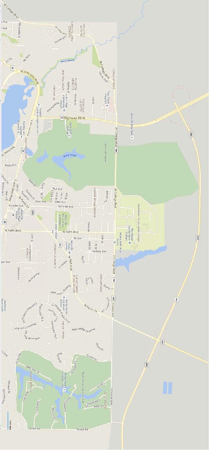
11 .BLDG 100 KEYNOTES WEST SIGN KEYNOTES EAST SIGN E COLLEGE BLVD E COLLEGE BLVD WEST MONUMENT SIGN EAST MONUMENT SIGN PREPARED FOR: FL AUTH: FL PE: DAN PROFESS L I EL J IC E NS E No WH STATE OF FLORIDA I ONA L I TE ENG I NEER 0' 10' 20' 30' ONE INCH EQUALS TEN FEET SCALE IN FEET NORTH ELECTRICAL SITE PLANS DESIGNED BY: DRAWN BY: REVIEWED BY: E2 DW
12 SHEET NOTES KEYNOTES ALUMINUM VENT FULL LED DISPLAY ALUMINUM BRICK REVEAL BRICK REVEAL LOGO SIGN BOX BRICK REVEAL E/WSN BRICK FINISH GRADE END ELEVATION TYPICAL EACH END SIDE ELEVATION TYPICAL EACH SIDE SIGN ELEVATION AND SINGLE LINE POWER RISER MONUMENT SIGN ROUGH IN DETAIL PREPARED FOR: FL AUTH: FL PE: DAN PROFESS L I EL J IC ENS E No WH STATE OF FLORIDA I ONA L I TE ENG I NEER 0' 10' 20' 30' ONE INCH EQUALS TEN FEET SCALE IN FEET NORTH ELECTRICAL ELEVATIONS, SINGLE LINE, AND DETAILS DESIGNED BY: DRAWN BY: REVIEWED BY: E3 DW
13 Arc Flash and Shock Hazard Appropriate PPE Required 22" 1.53 #5 Flash Hazard Boundary cal/cm2 Flash Hazard at 18 inches PPE Level FR shirt and FR pants or FR coverall 480V 42" 12" 1" VAC Shock Hazard when cover is removed Limited Approach Restricted Approach - Class 1 Voltage Gloves Prohibited Approach - Class 1 Voltage Gloves TYPICAL ELECTRICAL EQUIPMENT NAMEPLATE Equipment Name: PANEL MDP VALID FOR NORMAL SYSTEM CONFIGURATION ONLY. TYPICAL ARC FLASH HAZARD LABEL DETAIL BACK VIEW FRONT VIEW 90 DEGREE AND 180 DEGREE DOOR STOP BRACKET SIDE VIEW 1 HOLE FAN PANEL SWITCH BKT 22.5" LONG UNISTRUT (2X) CONDUIT MARKER DETAIL UNDERGROUND CONDUIT DETAIL BOTTOM VIEW GROUND MOUNTING STRAPS NOTES: ALUMINUM ENOSURE DETAIL PREPARED FOR: FL AUTH: FL PE: DAN PROFESS L I EL J IC ENS E No WH STATE OF FLORIDA I ONA L I TE ENG I NEER 0' 10' 20' 30' ONE INCH EQUALS TEN FEET SCALE IN FEET NORTH ELECTRICAL DETAILS DESIGNED BY: DRAWN BY: REVIEWED BY: E4 DW
Residential Construction Checklist Single and Two Family Construction
 DATE: _ Building Inspection Submittal Requirements Residential Construction Checklist Single and Two Family Construction Submit a City of Big Spring Permit Application, checklist, and 3 complete hard copy
PROJECT LOCATION BOZEMAN HIGH SCHOOL. ELECTRICAL ENGINEER: Van Dykken Engineering 37 Spanish Peak Drive Bozeman, MT Phone:
 DRAWING INDEX GENERAL C. PROJECT COVER G-WING A/V IMPROVEMENTS.0 AREA PLAN ST FLOOR SOUTH. TYP. PROJECTOR MOUNTING & PROJECTOR NOTES.2 G-WING TECHNOLOGY CABINET ELEVATIONS.3 G-WING WIRING DIAGRAM.4 G-WING
PREFACE ********************************************************** IT IS NOT INTENDED THAT THESE STANDARDS BE COPIED AND USED AS A SPECIFICATION!
 PREFACE This publication has been prepared as a guide for Architectural and Engineering (A&E) firms in the preparation of documents for the design and construction of new structures and the remodeling
A. Product Data: For each electrical identification product indicated.
 SECTION 16075 - ELECTRICAL IDENTIFICATION PART 1 - GENERAL 1.1 RELATED DOCUMENTS A. Drawings and general provisions of the Contract, including General and Supplementary Conditions and Division 1 Specification
Arc Flash and NFPA 70E
 Arc Flash and NFPA 70E Presented by: J.D. Kyle Safe Work Practices Wearing Proper PPE? OSHA 1910.333 (a) (1) not to work hot or live except : 1. De energizing introduces additional or increased hazards
Michigan State University Construction Standards WIRING DEVICES PAGE
 PAGE 262726-1 SECTION 262726 PART 1 - GENERAL 1.1 RELATED DOCUMENTS A. Drawings and general provisions of the Contract, including General and Supplementary Conditions and Division 01 Specification Sections,
Excavating, Backfilling, and Compaction for Utilities Piping (Plumbing).
.") SECTION 15047 - IDENTIFICATION PART 1 GENERAL 1.01 SUMMARY A. Section Includes: Identification including necessary accessories indicated on Construction Documents and specified in this section or as required
SECTION 15047 - IDENTIFICATION PART 1 GENERAL 1.01 SUMMARY A. Section Includes: Identification including necessary accessories indicated on Construction Documents and specified in this section or as required
Quality Control Checklist - Design Drawings
 Quality Control Checklist - Design Drawings Date Company Name Address Telephone Fax Email Job Number 1) Drawing Set a) Drawing one is site/location/incoming power i) Should contain location map if not
AN EXAMPLE OF A STANDARD ARC FLASH PPE LABELING STRATEGY
 The Electrical Power Engineers Qual-Tech Engineers, Inc. 201 Johnson Road Building #1 Suite 203 Houston, PA 15342-1300 Phone 724-873-9275 Fax 724-873-8910 www.qualtecheng.com AN EXAMPLE OF A STANDARD ARC
POWER SERVICE DETAILS
 POWER SOURCE # POLE MOUNTED SERVICE TRANSFORMER BY POWER HANDHOLE 0/0V, -PHASE, SERVICE CONDUCTORS; -# AWG SERVICE CONDUCTOR AND -# AWG GROUNDED SERVICE CONDUCTOR (NEUTRAL) SERVICE XFMR SECONDARY. A 0V
Single-Family Dwelling Submittal Requirements
 Single-Family Dwelling Submittal Requirements The purpose of this guideline is to assist our customers in preparing for plan submittal. The items listed must be included before your plans can be accepted
CSP PSYCHIATRIC SERVICES UNIT SECTION IDENTIFICATION FOR HVAC PIPING AND EQUIPMENT
 SECTION 23 05 53 IDENTIFICATION FOR HVAC PIPING AND EQUIPMENT PART 1 GENERAL 1.1 SUMMARY A. Section Includes: 1. Pipe Markers. 2. Valve Tags. 3. Equipment Nameplates. 4. Underground Marking Tape. 5. Duct
1. All electrical switches and outlets used shall be equal to Hubbell heavy duty, specification grade or equivalent quality.
 PART 1: GENERAL 1.01 Wiring Devices A. This section of the standard includes design requirements for wiring connections, including receptacles and switches to equipment specified in other sections. 1.02
NFPA-70E. Electrical Safety in the Workplace. Standard for Edition
 NFPA-70E Standard for Electrical Safety in the Workplace 2015 Edition NFPA-70E 90.1 Purpose. The purpose of this standard is to provide a practical safe working area for employees relative to the hazards
AN EXAMPLE OF A STANDARD ARC FLASH PPE LABELING STRATEGY
 The Electrical Power Engineers Qual-Tech Engineers, Inc. 201 Johnson Road Building #1 Suite 203 Houston, PA 15342-1300 Phone 724-873-9275 Fax 724-873-8910 www.qualtecheng.com AN EXAMPLE OF A STANDARD ARC
NORTH HARRIS COUNTY REGIONAL WATER AUTHORITY. Section ELECTRICAL IDENTIFICATION
 PART 1 GENERAL 1.01 SUMMARY Section 16195 A. This Section includes electrical identification for the following: 1. Nameplates and labels 2. Wire and cable markers 3. Conduit markers 4. Cable tray markers
Steve Kovach District Sales Engineer
 Steve Kovach District Sales Engineer 630-740-7463 Steveekovach@Eaton.com Institute of Electrical and Electronics Engineers American Society of Safety Engineers 1 Electrical Hazards Electrical Hazards Shock
PROJECT TITLE PROJECT NO: CONTRACT TITLE GRANT NO: UNIVERSITY OF CALIFORNIA, DAVIS CITY, CALIFORNIA
 The following standard specification is intended to be edited according to the specifics of the project. Brackets [ ] and areas shaded in gray [e.g. format] indicate requirements that are optional depending
SECTION SHORT CIRCUIT, COMPONENT PROTECTION, FLASH HAZARD AND SELECTIVE COORDINATION STUDY
 SECTION 16075 - SHORT CIRCUIT, COMPONENT PROTECTION, FLASH HAZARD AND SELECTIVE COORDINATION STUDY PART 1 GENERAL 1.1 SUMMARY A. Section Includes: 1. Provide a short-circuit, component protection, flash
B. Manufacturers: Square-D, G.E. or Westinghosue.
 SECTION 16470 - PANELBOARDS PART 1 - GENERAL 1.01 RELATED DOCUMENTS A. General: Drawings and general provisions of the Contract, including General and Supplementary Conditions and Division 1 Specification
SECTION EQUIPMENT WIRING
 PART 1 - GENERAL 1.01 RELATED DOCUMENTS: SECTION 26 27 17 EQUIPMENT WIRING A. The Conditions of the Contract and applicable requirements of Divisions 0 and 1 and Section 26 00 01, Electrical General Provisions,
SECTION LOW-VOLTAGE ELECT. DIST. DESIGN AND CONSTRUCTION STANDARDS _ February 2015 PART I: GENERAL
 PART I: GENERAL 1.01 Wiring Devices A. This section of the standard includes design requirements for wiring connections, including receptacles and switches to equipment specified in other sections. a.
Piping & Equipment Identification
 Piping & Equipment Identification Part 1 General 1.01 Description of Work A. Work in this section includes: Identification materials, including necessary accessories indicated on Contract Documents and
DOCUMENT ADDENDUM NO. 4. Issued to all Bidders: Date: October 14, Contract Name: Electrical Installation. Contract Number: C8410
 DOCUMENT 009104 - ADDENDUM NO. 4 Issued to all Bidders: Date: October 14, 2015 Contract Name: Electrical Installation Contract Number: C8410 This addendum forms a part of the Bid described above. The original
Michigan State University Construction Standards SWITCHBOARDS, PANELBOARDS, AND CONTROL CENTERS PAGE
 PAGE 262400-1 SECTION 262400 PART 1 - GENERAL 1.1 RELATED DOCUMENTS A. Drawings and general provisions of the Contract, including General and Supplementary Conditions and Division 01 Specification Sections,
PART 0 DESIGN STANDARDS 0.01 GENERAL DESIGN GUIDELINES
 PART 0 DESIGN STANDARDS 0.01 GENERAL DESIGN GUIDELINES A. Assign unit identification numbers to operating units of equipment within a class or subclass during the design phase of new buildings, additions,
Paul Dobrowsky Innovative Technology Services
 Significant Changes to NFPA 70E -2009 Edition Paul Dobrowsky Innovative Technology Services 2008 IEEE PCIC 1 Repeat Presentation This has been previously presented 2008 IEEE Electrical Safety Workshop
 CONTRACTOR(S) SHALL VERIFY EXISTING CONDITIONS AND CORRELATE DIMENSIONS PRIOR TO PROVIDING THE WORK DETAILED IN THESE DRAWINGS, AND SHALL PROMPTLY NOTIFY THE ARCHITECT OF ANY DISCREPANCIES. COPYRIGHT SBLM,
SECTION MECHANICAL IDENTIFICATION
 PART 1 GENERAL 1.1 RELATED DOCUMENTS A. Drawings and general provisions of the Contract, including General and Supplementary Conditions Specification Sections, apply to this Section. B. Related Sections:
NEW SEVICE CENTER BOB HART CHEVROLET. 495 S. 7th St. E:\RE Smith New Logo.jpg VINITA, OK RE SMITH BOB HART CHEVROLET NEW SERVICE CENTER
 NEW SEVICE CENTER VINITA, OK 70 9 S. 7th St. VINITA, OK 70 06 W. 2nd St., Joplin, MO 680 Phone: 7-62- Fax: 7-782-678 GENERAL G0.0 COVER CIVIL C.0 SITE DEMO C. SITE PLAN C.2 GRADING PLAN (FORTHCOMING) ARCHITECTURAL
Design Approaches for Hospital Distribution Systems With Considerations for Future Expansion, Operator Safety, and Cost
 Design Approaches for Hospital Distribution Systems With Considerations for Future Expansion, Operator Safety, and Cost Adam T. Powell, PE President Emerald Engineering, Inc. Jeffrey L. Small, Sr. Senior
SECTION PANELBOARDS
 PART 1 - GENERAL 1.1 DESCRIPTION SECTION 26 24 16 PANELBOARDS SPEC WRITER NOTE: Delete between // --- // if not applicable to project. Also, delete any other item or paragraph not applicable in the section
A. Submit properly identified manufacturer's literature before starting work.
 SECTION 10400 IDENTIFYING DEVICES PART 1 GENERAL 1.01 SUMMARY A. Section Includes: Labor and materials required for installation of plaque, school name and address numbers, directional signage, signage
2018 Consultant s Handbook Division 26 Electrical ARC Flash Hazard Analysis
 1 Summary 1.1 Provide a complete Arc Flash Hazard Analysis for the project indicated in the accompanying RFP. The Analysis may be performed: independent of the construction project in concert with the
Procurement Department Bid Office Customer Center 1 st Floor, Room W. Church Street Jacksonville, Florida 32202
 Procurement Department Bid Office Customer Center 1 st Floor, Room 002 21 W. Church Street Jacksonville, Florida 32202 May 24, 2017 ADDENDUM NUMBER: Three (3) TITLE: Construction Services for Arlington
SUBMITTAL REQUIREMENTS FOR COMMERCIAL BUILDING PROJECTS
 SUBMITTAL REQUIREMENTS FOR COMMERCIAL BUILDING PROJECTS When submitting your application for Commercial projects please include the following: 1. Completed Building Permit Application with page 2 stamped
UNIFIED FACILITIES GUIDE SPECIFICATIONS
 USACE / NAVFAC / AFCEC / NASA UFGS-11 47 00 (February 2009) ----------------------------- Preparing Activity: USACE Superseding UFGS-11 47 00 (January 2008) UNIFIED FACILITIES GUIDE SPECIFICATIONS References
First Draft Language
 110.16 First Draft Language (B) Service Equipment. In addition to the requirements in (A), service equipment shall contain the following information: (1) Nominal system voltage (2) Arc flash boundary (3)
SECTION IDENTIFYING DEVICES
 SECTION 10400 IDENTIFYING DEVICES PART 1 GENERAL 1.01 SUMMARY A. Section Includes: Labor and materials required for installation of plaque, school name and address numbers, directional signage, signage
SECTION MECHANICAL IDENTIFICATION
 SECTION 15190 MECHANICAL IDENTIFICATION PART 1 - GENERAL 1.01 SUMMARY A. Section Includes: 1. Identification of mechanical products installed under Division 15. B. Related Sections: 1.02 REFERENCES 1.
NEC 2014 Code Changes
 NEC 2014 Code Changes Articles 200-215.3 CHANGES FROM 2011 CODE ARE IN RED Chapter 2 - Wiring and Protection ARTICLE 200 Use and Identification of Grounded Conductors 200.2 General Grounded Conductors
ADDENDUM NO. 3 PROJECT: COURTLAND PUMP STATION CONTRACT: IFB NO COM.00030
 ADDENDUM NO. 3 PROJECT: COURTLAND PUMP STATION CONTRACT: IFB NO. 2018-008-COM.00030 To: Prospective Bidders of Record Date: January 8, 2019 The following changes, additions, revisions, and/or deletions
*********************************************************************************************************
 10400 IDENTIFYING DEVICES ********************************************************************************************************* SPECIFIER: CSI MasterFormat 2004 number: 10 14 00 *********************************************************************************************************
Article 225: Outside Branch Circuits And Feeders
 Part C: Code Book Questions Article 225: Outside Branch Circuits And Feeders 1.! Open (individual) aerial overhead conductors shall be insulated or covered when within! feet of a building.! (a) 10! (c)
SECTION ELECTRICAL IDENTIFICATION
 SECTION 16075 ELECTRICAL IDENTIFICATION PART 1 - GENERAL 1.01 RELATED DOCUMENTS A. Drawings and general provisions of the Contract, including General and Supplementary Conditions and Division 01 Specification
SECTION DISTRIBUTION SWITCHBOARDS
 PART 1 - GENERAL 1.1 DESCRIPTION SECTION 26 24 13 DISTRIBUTION SWITCHBOARDS SPEC WRITER NOTE: Delete between // -- // if not applicable to project. Also delete any other item or paragraph not applicable
UNIVERSITY SERVICES ANNEX James Madison University Harrisonburg, Virginia State Project Code: Architect s Project Number:
 SECTION 230553 - IDENTIFICATION FOR HVAC PIPING AND EQUIPMENT PART 1 - GENERAL 1.1 RELATED DOCUMENTS A. Provisions of the Contract and of the Contract Documents apply to this Section. 1.2 SUBMITTALS A.
SECTION MECHANICAL IDENTIFICATION
 SECTION 15190 MECHANICAL IDENTIFICATION PART 1 GENERAL 1.01 SECTION INCLUDES A. Section Includes: 1. Nameplates. 2. Tags. 3. Stencils. 4. Pipe Markers. 1.02 SUBMITTALS A. Submit valve chart and schedule,
SECTION COMMUNICATIONS ELECTRICAL POWER DISTRIBUTION
 SECTION 16715 COMMUNICATIONS ELECTRICAL POWER DISTRIBUTION PART 1 - GENERAL 1.01 SECTION DESCRIPTION AND BASIC REQUIREMENTS A. The Electrical Power Distribution System provides power distribution from
2015 NFPA 70E. SESHA 2015 ARIZONA MINI CONFERENCE December 10, 2015 Intel Corporation
 2015 NFPA 70E SESHA 2015 ARIZONA MINI CONFERENCE December 10, 2015 Intel Corporation Introduction Jeffrey A. Pugh, P.E. Pugh Engineering LLC Bachelor of Science Degrees in Electrical Engineering and Computer
STANDARDIZING ARC FLASH PPE LABELS
 The Electrical Power Engineers Qual-Tech Engineers, Inc. 01 Johnson Road Building #1 Suite 03 Houston, PA 1534-1300 Phone 74-873-975 Fax 74-873-8910 www.qualtecheng.com STANDARDIZING ARC FLASH PPE LABELS
B. Samples: For color, letter style, and graphic representation required for each identification material and device.
 PART 1 - GENERAL 1.01 RELATED DOCUMENTS A. Drawings and general provisions of the Contract, including General and Supplementary Conditions and Division 01 Specification Sections, apply to this Section.
OCPS Submittal Register for Product Data and Shop Drawing Reviews
 OCPS mittal Register for Product Data and Shop Drawing s Project ification Drawings - D Shop Drawings - Product Data - Test - TR Test Data - TD Calculations - Calc Certification - Cert 02 22 27 Pre-demolition
Industrial Pipe Marking
 Industrial Pipe Marking Pipe and Valve Identification Specialists SPECIFICATIONS ASME (ANSI) Standard A13.1-2007 The ASME (ANSI) Standard for pipe identification is a widely used guideline in determining
1. This Section specifies the ethernet Category 5E data cabling system for buildings and structures.
 PAGE 271200-1 SECTION 271200 PART 1 - GENERAL 1.1 RELATED DOCUMENTS A. Drawings and general provisions of the Contract, including General and Supplementary Conditions and Division 01 Specification Sections,
DIVISION 26 ELECTRICAL SECTION ELECTRICAL
 DIVISION 26 ELECTRICAL SECTION 26 1000 ELECTRICAL PART 1 - GENERAL 1.1 WORK INCLUDED A. Furnish all labor, material and equipment necessary for the complete installation of the Electrical System as shown
SECTION MECHANICAL IDENTIFICATION
 Buebtel/Perlcins Community Learning Center GPD - 2001271.15 SECTION 15075 MECHANICAL IDENTIFICATION PART 1- GENERAL 1.1 RELATED DOCUMENTS A. Drawings and general provisions of the Contract, including General
SECTION IDENTIFICATION FOR PLUMBING PIPING AND EQUIPMENT
 SECTION 220553 - IDENTIFICATION FOR PLUMBING PIPING AND EQUIPMENT Henderson Engineers, Inc. PART 1 - GENERAL REQUIREMENTS 1.1 SUMMARY A. Extent of Plumbing work to be identified as required by this Section
M1.0 MECHNANICAL FLOOR PLAN
 GENERAL NOTES A. CONTRACTORS AND SUB CONTRACTORS SHALL CAREFULLY REVIEW THE CONSTRUCTION DOCUMENTS. INFORMATION REGARDING THE COMPLETE WORK IS DISPERSED THROUGHOUT THE DOCUMENT SET AND CANNOT BE ACCURATELY
SECTION MECHANICAL IDENTIFICATION. 1. Identification of mechanical products installed under Division 15.
 SECTION 15190 MECHANICAL IDENTIFICATION PART 1 - GENERAL 1.01 SUMMARY A. Section Includes: 1. Identification of mechanical products installed under Division 15. B. Related Sections: 1. Section 09900 -
SECTION IDENTIFYING DEVICES
 PART 1 GENERAL 1.1 RELATED DOCUMENTS SECTION 10441 IDENTIFYING DEVICES A. Drawings and general provisions of the Contract, including General and Supplementary Conditions and Division-1 specification section,
UNIFIED FACILITIES GUIDE SPECIFICATIONS
 USACE / NAVFAC / AFCEC / NASA UFGS-11 47 00 (August 2017) ----------------------------- Preparing Activity: USACE Superseding UFGS-11 47 00 (February 2009) UNIFIED FACILITIES GUIDE SPECIFICATIONS References
SECTION CABLE TRAYS FOR COMMUNICATIONS SYSTEMS
 SECTION 270536 - CABLE TRAYS FOR COMMUNICATIONS SYSTEMS PART 1 - GENERAL 1.1 RELATED DOCUMENTS A. Drawings and general provisions of the Contract, including General and Supplementary Conditions and Division
STANDARD COMMENTS 2016 ELECTRICAL PLAN REVIEW CHECK LIST
 STANDARD COMMENTS 2016 ELECTRICAL PLAN REVIEW CHECK LIST Item Comments 1. The electrical plan check is approved and ready to have the electrical permit issued, pending the building permit being issued.
New Co-Brand Convenience Store McPherson, Kansas SECTION BASIC METHODS AND REQUIREMENTS PART 1 - GENERAL 1.1 GENERAL CONDITIONS:
 SECTION 16050 - BASIC METHODS AND REQUIREMENTS PART 1 - GENERAL 1.1 GENERAL CONDITIONS: A. The General Conditions, Supplementary General Conditions, General Requirements, and Special Conditions shall be
SECTION DISTRIBUTION SWITCHBOARDS
 PART 1 - GENERAL 1.1 DESCRIPTION SECTION 26 24 11 SPEC WRITER NOTES: Use this section only for NCA projects. Delete between // -- // if not applicable to project. Also delete any other item or paragraph
SECTION IDENTIFICATION FOR FIRE SUPPRESSION PIPING AND EQUIPMENT
 SECTION 21 05 53 IDENTIFICATION FOR FIRE SUPPRESSION PIPING AND EQUIPMENT Display hidden notes to specifier. (Don't know how? Click Here) Copyright 2015-2015 ARCAT, Inc. - All rights reserved PART 1 GENERAL
MECKLENBURG COUNTY. Land Use and Environmental Service Agency Code Enforcement 2/9/11 ELECTRICAL CONSISTENCY MEETING. Code Consistency Questions
 MECKLENBURG COUNTY Land Use and Environmental Service Agency Code Enforcement 2/9/11 ELECTRICAL CONSISTENCY MEETING Code Consistency Questions 1. I have a 500 KVA generator, with no overcurrent protection
University of Central Florida Main Campus. Electric. Service and Meter Installations Requirements. Issued January 26 th, 2017.
 University of Central Florida Main Campus Electric Service and Meter Installations Requirements Issued January 26 th, 2017 1 P a g e Table of Contents 1. GENERAL INFORMATION... 3 2. DEFINITIONS... 3 3.
Journeyman's Practice Exam
 Journeyman's Practice Exam [Time limit 4.0 hrs.] (The test is open book. I've started at the front of the Code Book and worked toward the back for instructional purposes. The real test will not be in order
BUILDING PLAN REVIEW REQUIREMENTS
 TOWNSHIP OF NORTH FAYETTE BUILDING DEPARTMENT COMMERCIAL PLAN REVIEW REQUIREMENTS BUILDING PLAN REVIEW REQUIREMENTS In order to perform a thorough Building Plan Review, the following specifications, drawings
Brown University Revised 2/1/2006 Facilities Design & Construction Requirements SECTION 16461C - DRY TYPE TRANSFORMERS
 SECTION 16461C - DRY TYPE TRANSFORMERS PART 1 - GENERAL 1.1 This section includes design and performance requirements for dry-type transformers rated for use on secondary distribution systems rated 600
St. Monica Food Pantry
 St. Monica Food Pantry 26 5113-1 ELECTRICAL WORK DIVISION 26 SECTION 265113 INTERIOR LIGHTING FIXTURES PART 1. GENERAL 1.1 WORK INCLUDES A. Extent, location, and details of interior lighting fixture work
This section applies to the requirements for the performance of power system studies by both the Design Engineer and the Contractor.
 Basis of Design This section applies to the requirements for the performance of power system studies by both the Design Engineer and the Contractor. Background Information A Short Circuit and Coordination
SECTION OVERCURRENT PROTECTIVE DEVICE COORDINATION STUDY
 PART 1 - GENERAL 1.1 DESCRIPTION SECTION 26 05 73 OVERCURRENT PROTECTIVE DEVICE COORDINATION STUDY SPEC WRITER NOTE: Delete between // -- // if not applicable to project. Also, delete any other item or
Bid No. B14-02 Building 100 HVAC Improvements
 Bid No. B14-02 Building 100 HVAC Improvements Addendum No. 1 This Addendum No. 1 sets forth modifications to portions of the bid and contract documents for the above-referenced work described as: Building
Electrical Overcurrent Studies
 Electrical Overcurrent Studies 11-01-2011 Deliverables associated with electrical overcurrent studies are as follow : a. Draft Reports i. Construction Related Projects have the following draft reports
SECTION CABLE TRAYS
 SECTION 16139 CABLE TRAYS PART 1 - GENERAL 1.1 RELATED DOCUMENTS A. Drawings and general provisions of the Contract, including General and Supplementary Conditions and Division 1 Specification Sections,
CITY OF NEW ROCHELLE RENOVATIONS TO FIRE STATION NO WEBSTER AVENUE, NEW ROCHELLE, NEW YORK
 AREVIATIONS AFF AOVE FINISHED FLOOR AHJ AUTHORITIES HAVING JURISDICTION APPROX APPROXIMATE LDG UILDING CLG CEILING CONST CONSTRUCTION CD CEILING DIFFUSER CO CARON DIOXIDE CXA COMMISSIONING AGENT DEG DEGREES
Non-Residential and Multi-Family Plan Check Submittal Requirements
 Phone (310) 605-5509 Fax Line (310) 605-5598 E-mail: www.comptoncity.org City of Compton Building & Safety Department Non-Residential and Multi-Family Plan Check Submittal Requirements The purpose of this
SECTION LIGHTING PART 1- GENERAL
 SECTION 16500 LIGHTING PART 1- GENERAL 1.01 WORK INCLUDED A. The Contractor shall provide all lighting fixtures, panelboards, labor, material, etc., in accordance with the preceding specifications, the
SPECIAL SPECIFICATION LIGHTNING PROTECTION SYSTEM
 2004 Specifications CSJ 3622-01-001, ETC. SPECIAL SPECIFICATION 8398 LIGHTNING PROTECTION SYSTEM 1. Description. This Special Specification governs the design and installation of Lightning Protection System
SPARTAN DAY CAMP 4814 FREEDOM RING RD
 484 FREEDOM RING RD PROJECT DATA GENERAL PROJECT NOTES: LOCATION:. DIMENSIONS ARE TO FACE OF STUD OR TO COLUMN CENTERLINE UNLESS NOTED OTHERWISE. VERIFY ALL EXISTING CONDITIONS AND ADJUST WALL DIMENSIONS
Electrical Arc Hazards
 Arc Flash Analysis 1996-2009 ETAP Workshop Operation Notes Technology, 1996-2009 Inc. Operation Workshop Technology, Notes: Arc Inc. Flash Analysis Slide 1 Electrical Arc Hazards Electrical Arcs can occur
SECTION SIGNAGE
 SECTION 10 14 00 SIGNAGE PART 1 GENERAL 1.1 RELATED DOCUMENTS A. Drawings and general provisions of the Contract, including General and Supplementary Conditions and Division-1 specification section, apply
ADDENDUM NO. 2 PROJECT: COURTLAND PUMP STATION CONTRACT: IFB NO COM.00030
 ADDENDUM NO. 2 PROJECT: COURTLAND PUMP STATION CONTRACT: IFB NO. 2018-008-COM.00030 To: Prospective Bidders of Record Date: December 17, 2018 The following changes, additions, revisions, and/or deletions
1. Name the horizontal member that rests on the foundation wall to support other wood members.
 Student Name: Teacher: Date: District: Rowan Assessment: 9_12 T and I IC62 - Drafting - Architr II Test 1 Description: Unit C - Floorplans - Test 3 (ALL) Form: 501 1. Name the horizontal member that rests
FIRE STATION NO TH STREET NORTH ST. PETERSBURG, FL M-1 SCOPE OF WORK SYMBOL DESCRIPTION SYMBOL DESCRIPTION HVAC SYMBOL LEGEND
 HVAC SYMBOL LEGEND HVAC PIPING AND VALVES LEGEND HVAC GENERAL NOTES SCOPE OF WORK SYMBOL DESCRIPTION SYMBOL DESCRIPTION SYMBOL DESCRIPTION SYMBOL DESCRIPTION PHASING OF WORK HVAC ABBREVIATIONS ABBREVIATION
HOENER ASSOCIATES INC. ARCHITECTS
 HOENER ASSOCIATES INC. ARCHITECTS BRUCE D. DELL MARK REUTHER ADDENDUM NO. 1 PROJECT 15-22C RENOVATION AND SITE WORK AT: BUILDING B DDRB OF ST. CHARLES DEVELOPMENT DISABILITIES RESOURCE BOARD ST. CHARLES,
SECTION WIRE AND CABLES. A. The CONTRACTOR shall provide wires and cable, complete and operable, in accordance with the Contract Documents.
 SECTION 26 05 19 PART 1 - GENERAL 1.1 THE REQUIREMENT A. The CONTRACTOR shall provide wires and cable, complete and operable, in accordance with the Contract Documents. 1.2 CONTRACTOR SUBMITTALS A. The
DESIGN CHECKLIST INTRODUCTION
 INTRODUCTION 1 The checklist is intended to serve as a convenient guide in design development as well as the final checking of plans and specifications for construction projects. Its main usefulness for
STATE UNIVERSITY CONSTRUCTION FUND
 DIRECTIVE 1C-12 Issue date: August 2012 1. General SURVEY, MAPPING AND UTILITY LOCATING This Directive has been developed as a general guide for the survey and mapping effort required for Fund projects.
Spec Section: , Complete Elec, Comm, and Fire Alarm , Complete Elec, Comm, and Fire Alarm Data Sheets RAN/GCAN
 SUBMITTAL REVIEW Submittal: No. 019.00 Spec Section: 26 0000, 28 0000 Complete Elec, Comm, and Fire Alarm Reviewed By: Laura Landon, Comma-Q Architecture Date: June 29, 2012 Project: BPS Belgrade Elementary
Arc Flash Analysis and Documentation SOP
 Arc Flash Analysis and Documentation SOP I. Purpose.... 2 II. Roles & Responsibilities.... 2 A. Facilities Maintenance (FM).... 2 B. Zone Supervisors/ Shop Foremen... 2 C. PMCS & CPC... 2 III. Procedures...
SECTION EMERGENCY RESPONDER RADIO COVERAGE SYSTEMS
 510.1 Emergency responder radio coverage in new buildings. Approved radio coverage for emergency responders shall be provided within all buildings meeting any one of the following conditions: 1. There
SUGGESTED SPECIFICATION for Series 300 Automatic Transfer Switches
 SUGGESTED SPECIFICATION for Series 300 Automatic Transfer Switches PART 1 GENERAL 1.01 Scope Furnish and install automatic transfer switches (ATS) with number of poles, amperage, voltage, and withstand
Design Deliverables. Summary. A. Expectations for Design Deliverables:
 Design Deliverables Summary A. Expectations for Design Deliverables: The Design Team is obligated to advance and deliver the project with a professional manner and standard of care that meets the expectations
ELECTRICAL GENERAL DESIGN AND CONSTRUCTION STANDARD PART 1: GENERAL Electrical/Telecommunications Design
 PART 1: GENERAL 1.01 Electrical/Telecommunications Design A. This section of the design and construction standard outlines general requirements for electrical and telecommunications designs to be performed
Electrical requirements for plans on all new homes, additions, remodels & Service upgrades
 CHERRY HILLS VILLAGE COLORADO Electrical requirements for plans on all new homes, additions, remodels & Service upgrades Due to the size and uniqueness of homes built in Cherry Hills Village, a policy
SECTION PROJECT COORDINATION VIA BIM
 SECTION 01 31 13 PROJECT COORDINATION VIA BIM PART 1 - GENERAL 1.1 RELATED DOCUMENTS A. Drawings and general provisions of the Contract, including General and Supplementary Conditions and other Division