Features. Gate. G C E Emitter. Product Marking Quantity DGTD65T50S1PT DGTD65T50S1 450 per Box in Tubes (Note 5)
|
|
|
- Wesley Shields
- 5 years ago
- Views:
Transcription
 = 1.85V @ I C = 50A High Input Impedance t rr = 80ns (typ) @ di F/dt = 1000A/µs E off = 0.")
 Applications Mechanical Data UPS Welder Solar Inverter IH Cooker Case: TO-247 (Type MC) Case Material: Molded Plastic. Green Molding Compound.")
1 650V FIELD STOP IGBT IN TO-247 Description The is produced using advanced Field Stop Trench IGBT Technology, which provides excellent quality and high-switching performance. Features High-Speed Switching & Low Power Loss V CE(sat) = I C = 50A High Input Impedance t rr = 80ns di F/dt = 1000A/µs E off = T C=25 C Maximum Junction Temperature 175 C Lead-Free Finish & RoHS Compliant (Notes 1 & 2) Halogen and Antimony Free. Green Device (Note 3) Applications Mechanical Data UPS Welder Solar Inverter IH Cooker Case: TO-247 (Type MC) Case Material: Molded Plastic. Green Molding Compound. UL Flammability Classification Rating 94V-0 Terminals: Finish Matte Tin Plated Leads. Solderable per MIL-STD-202, Method 208 Weight: 5.6 grams (Approximate) Collector Gate G C E Emitter TO-247 Device Symbol Ordering Information (Note 4) Product Marking Quantity DGTD65T50S1 450 per Box in Tubes (Note 5) Notes: 1. EU Directive 2002/95/EC (RoHS), 2011/65/EU (RoHS 2) & 2015/863/EU (RoHS 3) compliant. All applicable RoHS exemptions applied. 2. See for more information about Diodes Incorporated s definitions of Halogen- and Antimony-free, "Green" and Lead-free. 3. Halogen- and Antimony-free "Green products are defined as those which contain <900ppm bromine, <900ppm chlorine (<1500ppm total Br + Cl) and <1000ppm antimony compounds. 4. For packaging details, go to our website at Devices per Tube. Marking Information DGTD 65T50S1 YYLLLLLWW = Manufacturer s Marking DGTD65T50S1 = Product Type Marking Code YY = Year (ex: 18 = 2018) LLLLL = Lot Code WW = Week (01 to 53) 1 of 9
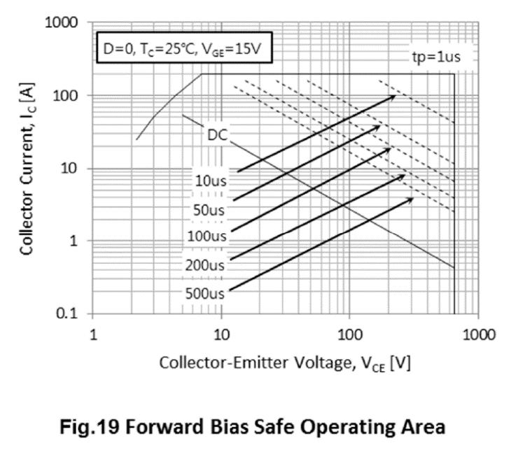
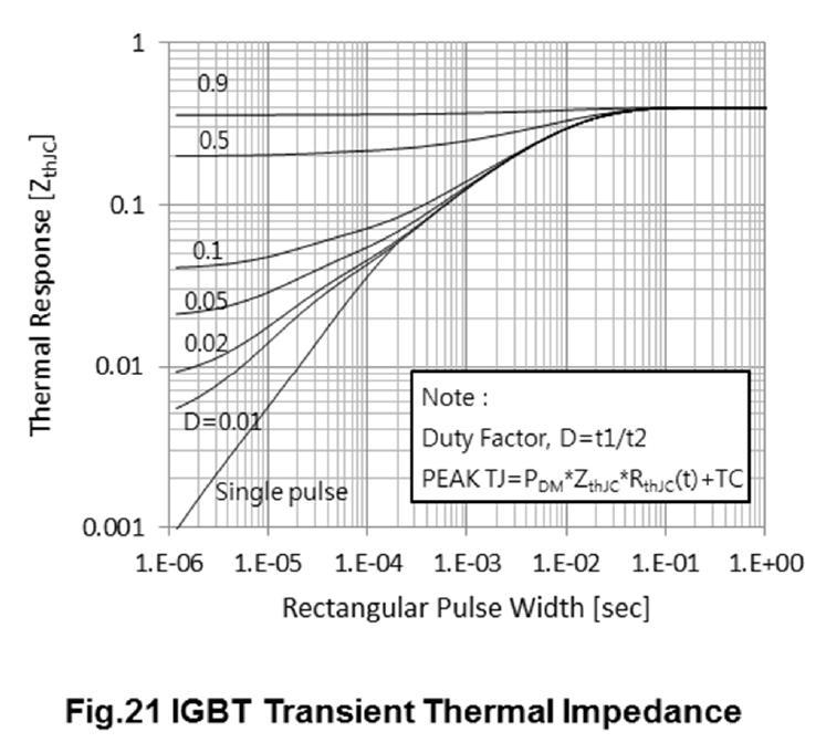
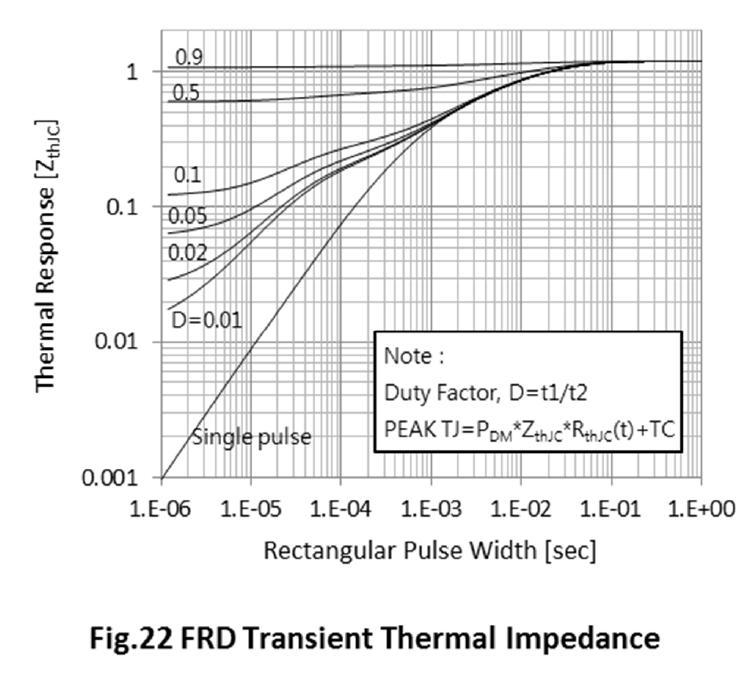
2 Absolute Maximum Ratings A = +25 C, unless otherwise specified.) Characteristic Symbol Value Unit Collector-Emitter Voltage V CE 650 V DC Collector Current, limited by T vjmax T C = 25 C 100 A I C T C = 100 C 50 A Pulsed Collector Current, t p limited by T vjmax I Cpuls 200 A Turn Off Safe Operating Area V CE 650V, T vj = 175 C A Diode Forward Current limited by T vjmax T C = 25 C 60 A I F T C = 100 C 30 A Diode Pulsed Current, t p limited by T vjmax I Fpuls 200 A Gate-Emitter Voltage V GE ±20 V Short Circuit Withstand Time V CC 400V, V GE = 15V, T vj = 150 C Allowed Number of Short Circuits < 1000 Time Between Short Circuits 1.0s tsc 5 µs Thermal Characteristics (@T A = +25 C, unless otherwise specified.) Characteristic Symbol Value Unit T C = 25 C 375 Power Dissipation Linear Derating Factor (Note 6) P D W T C = 100 C 188 Thermal Resistance, Junction to Ambient (Note 6) R θja 40 Thermal Resistance, Junction to Case for IBGT (Note 6) R θjc 0.40 Thermal Resistance, Junction to Case for Diode (Note 6) R θjc 1.20 Operating Temperature T vj -40 to +175 Storage Temperature Range T STG -55 to +150 C/W C Note: 6. When mounted on a standard JEDEC 2-layer FR-4 board. 2 of 9
3 Electrical Characteristics vj = +25 C, unless otherwise specified.) Parameter Symbol Min Typ Max Unit Condition STATIC CHARACTERISTICS Collector-Emitter Breakdown Voltage BV CES 650 V I C = 2mA, V GE = 0V Collector-Emitter Saturation Voltage T vj = 25 C V CE(sat) T vj = 175 C 2.20 V I C = 50A, V GE = 15V Diode Forward Voltage T vj = 25 C V F T vj = 175 C 1.55 V V GE = 0V, I F = 30A Gate-Emitter Threshold Voltage V GE(th) V V CE = V GE, I C = 0.5mA Zero Gate Voltage Collector Current I CES 40 µa V CE = 650V, V GE = 0V Gate-Emitter Leakage Current I GES ±100 na V GE = 20V, V CE = 0V DYNAMIC CHARACTERISTICS Total Gate Charge Q g 287 V nc CE = 520V, I C = 50A, Gate-Emitter Charge Q ge 42 V GE = 15V Gate-Collector Charge Q gc 181 Input Capacitance C ies 4,453 V pf CE = 25V, V GE = 0V, Reverse Transfer Capacitance C res 161 f = 1MHz Output Capacitance C oes 238 Internal Emitter Inductance Measured 5mm (0.197 ) From Case L E 13 nh Short Circuit Collector Current Max Short V GE = 15V, V CC = 400V, I C(SC) 140 A Circuits. Time Between Short Circuits 1.0s t SC 5µs, T vj = 150 C SWITCHING CHARACTERISTICS Turn-on Delay Time t d(on) 58 Rise time t r 60 Turn-off Delay Time t d(off) 328 Fall Time t f 44 Turn-on Switching Energy E on 0.77 ns V GE = 15V, V CC = 400V, I C = 50A, R G = 7.9Ω, Inductive Load, T vj = 25 C mj Turn-off Switching Energy E off 0.55 Total Switching Energy E ts 1.32 Reverse Recovery Time t rr 80 ns I F = 30A, Reverse Recovery Current I rr 24 A Reverse Recovery Charge Q rr 0.95 µc Turn-on Delay Time t d(on) 51 Rise time t r 66 Turn-off Delay Time t d(off) 350 Fall Time t f 49 Turn-on Switching Energy E on 1.05 Turn-off Switching Energy E off 0.55 Total Switching Energy E ts 1.6 di F/dt = 1000A/µs, T vj = 25 C ns V GE = 15V, V CC = 400V, I C = 50A, R G = 7.9Ω, Inductive Load, T vj = 175 C mj Reverse Recovery Time t rr 116 ns I F = 30A, Reverse Recovery Current I rr 34 A di F/dt = 1000A/µs, Reverse Recovery Charge Q rr 1.97 µc T vj = 175 C 3 of 9
4 Typical Performance Characteristics A = +25 C, unless otherwise specified.) 4 of 9
5 Typical Performance Characteristics (continued) 5 of 9
6 Typical Performance Characteristics (cont.) 6 of 9
7 Typical Performance Characteristics (cont.) 7 of 9
8 Package Outline Dimensions Please see for the latest version. TO-247 (Type MC) D L Q b2 e E e1 ØP D1 L1 b1 b A c A1 A2 E1 D2 TO-247 (Type MC) Dim Min Max Typ A A A b b b c D D D E E e e L L Q øp All Dimensions in mm Note : For high-voltage applications, the appropriate industry sector guidelines should be considered with regards to creepage and clearance distances between device Terminals and PCB tracking. 8 of 9
9 IMPORTANT NOTICE DIODES INCORPORATED MAKES NO WARRANTY OF ANY KIND, EXPRESS OR IMPLIED, WITH REGARDS TO THIS DOCUMENT, INCLUDING, BUT NOT LIMITED TO, THE IMPLIED WARRANTIES OF MERCHANTABILITY AND FITNESS FOR A PARTICULAR PURPOSE (AND THEIR EQUIVALENTS UNDER THE LAWS OF ANY JURISDICTION). Diodes Incorporated and its subsidiaries reserve the right to make modifications, enhancements, improvements, corrections or other changes without further notice to this document and any product described herein. Diodes Incorporated does not assume any liability arising out of the application or use of this document or any product described herein; neither does Diodes Incorporated convey any license under its patent or trademark rights, nor the rights of others. Any Customer or user of this document or products described herein in such applications shall assume all risks of such use and will agree to hold Diodes Incorporated and all the companies whose products are represented on Diodes Incorporated website, harmless against all damages. Diodes Incorporated does not warrant or accept any liability whatsoever in respect of any products purchased through unauthorized sales channel. Should Customers purchase or use Diodes Incorporated products for any unintended or unauthorized application, Customers shall indemnify and hold Diodes Incorporated and its representatives harmless against all claims, damages, expenses, and attorney fees arising out of, directly or indirectly, any claim of personal injury or death associated with such unintended or unauthorized application. Products described herein may be covered by one or more United States, international or foreign patents pending. Product names and markings noted herein may also be covered by one or more United States, international or foreign trademarks. This document is written in English but may be translated into multiple languages for reference. Only the English version of this document is the final and determinative format released by Diodes Incorporated. LIFE SUPPORT Diodes Incorporated products are specifically not authorized for use as critical components in life support devices or systems without the express written approval of the Chief Executive Officer of Diodes Incorporated. As used herein: A. Life support devices or systems are devices or systems which: 1. are intended to implant into the body, or 2. support or sustain life and whose failure to perform when properly used in accordance with instructions for use provided in the labeling can be reasonably expected to result in significant injury to the user. B. A critical component is any component in a life support device or system whose failure to perform can be reasonably expected to cause the failure of the life support device or to affect its safety or effectiveness. Customers represent that they have all necessary expertise in the safety and regulatory ramifications of their life support devices or systems, and acknowledge and agree that they are solely responsible for all legal, regulatory and safety-related requirements concerning their products and any use of Diodes Incorporated products in such safety-critical, life support devices or systems, notwithstanding any devices- or systems-related information or support that may be provided by Diodes Incorporated. Further, Customers must fully indemnify Diodes Incorporated and its representatives against any damages arising out of the use of Diodes Incorporated products in such safety-critical, life support devices or systems. Copyright 2018, Diodes Incorporated 9 of 9
Features. Gate. G C E Emitter. Product Marking Quantity DGTD120T25S1PT DGTD120T25S1 450 per Box in Tubes (Note 5)
") 1200V FIELD STOP IGBT IN TO-247 Description The is produced using advanced Field Stop Trench IGBT Technology, which provides low V CE(sat), excellent quality and high-switching performance. Features High
1200V FIELD STOP IGBT IN TO-247 Description The is produced using advanced Field Stop Trench IGBT Technology, which provides low V CE(sat), excellent quality and high-switching performance. Features High
Green. Features. Equivalent Circuit. Top View Pin Out Configuration. Part Number Case Packaging DMTH10H005SCT TO220AB 50 Pieces/Tube
 Green V +75 C N-CHANNEL ENHANCEMENT MODE MOSFET Product Summary R DS(ON) I D T C = +25 C V 5mΩ @V GS = V 4A BV DSS Description This new generation MOSFET features low on-resistance and fast switching,
Features. Part Number Marking Reel Size (inches) Tape Width (mm) Quantity Per Reel DGD2101MS8-13 DGD ,500
 Tape Width (mm) Quantity Per Reel DGD2101MS8-13 DGD ,500") HIGH-SIDE AND LOW-SIDE GATE DRIVER IN SO-8 (Type TH) Description The is a high-voltage / high-speed gate driver capable of driving N-Channel MOSFETs and IGBTs in a high-side/low-side configuration. High-voltage
HIGH-SIDE AND LOW-SIDE GATE DRIVER IN SO-8 (Type TH) Description The is a high-voltage / high-speed gate driver capable of driving N-Channel MOSFETs and IGBTs in a high-side/low-side configuration. High-voltage
Features. Bottom View Equivalent Circuit. Top View Pin Out Configuration. Part Number Case Packaging DMN80H2D0SCTI ITO220AB (Type TH) 50 pieces/tube
 50 pieces/tube") N-CHANNEL ENHANCEMENT MODE MOSFET Product Summary BV DSS R DS(ON) Package 8V Description.Ω@V GS = V ITOAB (Type TH) I D T C = +5 C This new generation MOSFET features low on-resistance and fast switching,
N-CHANNEL ENHANCEMENT MODE MOSFET Product Summary BV DSS R DS(ON) Package 8V Description.Ω@V GS = V ITOAB (Type TH) I D T C = +5 C This new generation MOSFET features low on-resistance and fast switching,
Features. Product Marking Reel Size (inch) Tape Width (mm) Quantity per Reel DGD2103MS8-13 DGD2103M ,500
 Tape Width (mm) Quantity per Reel DGD2103MS8-13 DGD2103M ,500") HALF-BRIDGE GATE DRIVER IN SO-8 Description The is a high-voltage / high-speed gate driver capable of driving N-channel MOSFETs and IGBTs in a half-bridge configuration. High voltage processing techniques
HALF-BRIDGE GATE DRIVER IN SO-8 Description The is a high-voltage / high-speed gate driver capable of driving N-channel MOSFETs and IGBTs in a half-bridge configuration. High voltage processing techniques
Green. Features G S. Pin Out Top View. Part Number Case Packaging DMNH6021SK3Q-13 TO252 (DPAK) 2,500/Tape & Reel
 2,500/Tape & Reel") Green 6V 7 C N-CHANNEL ENHANCEMENT MODE MOSFET Product Summary BV DSS 6V R DS(ON) max 23mΩ @ V GS = V 28mΩ @ V GS = 4.V Description and Applications I D max T C = +2 C A 4A This MOSFET is designed to meet
Green 6V 7 C N-CHANNEL ENHANCEMENT MODE MOSFET Product Summary BV DSS 6V R DS(ON) max 23mΩ @ V GS = V 28mΩ @ V GS = 4.V Description and Applications I D max T C = +2 C A 4A This MOSFET is designed to meet
Features. Product Marking Reel Size (inches) Tape Width (mm) Quantity per Reel DGD2304S8-13 DGD ,500
 Tape Width (mm) Quantity per Reel DGD2304S8-13 DGD ,500") HALF-BRIDGE GATE DRIVER IN SO-8 Description Features The is a high voltage / high speed gate driver capable of driving N-channel MOSFETs and IGBTs in a half bridge configuration. High voltage processing
HALF-BRIDGE GATE DRIVER IN SO-8 Description Features The is a high voltage / high speed gate driver capable of driving N-channel MOSFETs and IGBTs in a half bridge configuration. High voltage processing
B3XXAE B320AE-B345AE. Product Summary. Features and Benefits. Mechanical Data. Description and Applications NEW PRODUCT. Ordering Information (Note 4)
") Green 3.0A SCHOTTKY BARRIER RECTIFIER Product Summary B320AE/B330AE/B340AE/B345AE V RRM (V) I O (A) V F(MAX) (V) I R(MAX) (ma) @ +25 C @ +25 C 20 3 0.5 0. 30 3 0.5 0.15 40 3 0.5 0.20 45 3 0.5 0.30 Features
Green 3.0A SCHOTTKY BARRIER RECTIFIER Product Summary B320AE/B330AE/B340AE/B345AE V RRM (V) I O (A) V F(MAX) (V) I R(MAX) (ma) @ +25 C @ +25 C 20 3 0.5 0. 30 3 0.5 0.15 40 3 0.5 0.20 45 3 0.5 0.30 Features
Green. Part Number Case Packaging DMN3013LFG-7 PowerDI (Type D) 1000 / Tape & Reel DMN3013LFG-13 PowerDI (Type D) 3000 / Tape & Reel
 1000 / Tape & Reel DMN3013LFG-13 PowerDI (Type D) 3000 / Tape & Reel") YYWW Green 3V SYNCHRONOUS N-CHANNEL ENHANCEMENT MODE MOSFET PowerDI3333-8 (Type D) Product Summary Device BV DSS R DS(ON) Max Q 3V 4.3m @ V GS = 8V, I D = 4A Q2 3V 4.3m @ V GS = 8V, I D = 4A Description
YYWW Green 3V SYNCHRONOUS N-CHANNEL ENHANCEMENT MODE MOSFET PowerDI3333-8 (Type D) Product Summary Device BV DSS R DS(ON) Max Q 3V 4.3m @ V GS = 8V, I D = 4A Q2 3V 4.3m @ V GS = 8V, I D = 4A Description
Top View. Part Number Case Packaging DMTH4014LPDQ-13 PowerDI (Type C) 2,500/Tape & Reel
 2,500/Tape & Reel") 4V 75 C DUAL N-CHANNEL ENHANCEMENT MODE MOSFET Product Summary BV DSS 4V R DS(ON) max I D max T C = +25 C 5mΩ @ V GS = V 43.6A 25mΩ @ V GS = 4.5V 33A Description and Applications This MOSFET is designed
4V 75 C DUAL N-CHANNEL ENHANCEMENT MODE MOSFET Product Summary BV DSS 4V R DS(ON) max I D max T C = +25 C 5mΩ @ V GS = V 43.6A 25mΩ @ V GS = 4.5V 33A Description and Applications This MOSFET is designed
Features. Product Marking Reel Size (inches) Tape Width (mm) Quantity per Reel DGD21844S14-13 DGD ,500
 Tape Width (mm) Quantity per Reel DGD21844S14-13 DGD ,500") HALF- BRIDGE GATE DRIVER IN SO-14 Description The is a high voltage / high speed gate driver capable of driving N-Channel MOSFETs and IGBTs in a half bridge configuration. High voltage processing techniques
HALF- BRIDGE GATE DRIVER IN SO-14 Description The is a high voltage / high speed gate driver capable of driving N-Channel MOSFETs and IGBTs in a half bridge configuration. High voltage processing techniques
G1 S2. Top View. Part Number Case Packaging DMTH6010LPDQ-13 PowerDI (Type C) 2,500/Tape & Reel
 2,500/Tape & Reel") 6V 75 C DUAL N-CHANNEL ENHANCEMENT MODE MOSFET Product Summary BV DSS 6V R DS(ON) max I D max T C = +25 C mω @ V GS = V 47.6A 6mΩ @ V GS = 4.5V 39.5A Description and Applications This MOSFET is designed
6V 75 C DUAL N-CHANNEL ENHANCEMENT MODE MOSFET Product Summary BV DSS 6V R DS(ON) max I D max T C = +25 C mω @ V GS = V 47.6A 6mΩ @ V GS = 4.5V 39.5A Description and Applications This MOSFET is designed
Green SMC. Top View Bottom View. Part Number Case Packaging B5XXCE-13 SMC 3,000/Tape & Reel
 Green 5.0A SURFACE MOUNT SCHOTTKY BARRIER RECTIFIER Product Summary B520CE/B530CE/B540CE V RRM (V) I O (A) V F Max (V) I R Max (ma) 20 5.0 0.55 0.2 30 5.0 0.55 0.2 40 5.0 0.55 0.2 Features and Benefits
Green. Case Material: Molded Plastic. UL Flammability Classification 3.3V - 200V Nominal Zener Voltage Range
 Green 3.W SURFACE MOUNT POWER ENER DIODE Features Mechanical Data 3.W Power Dissipation Case: SMB Ideally Suited for Automated Assembly Case Material: Molded Plastic. UL Flammability Classification 3.3V
Green. Part Number Case Packaging SBRT3U60SAF-13 SMAF 10,000/Tape & Reel
 Green 3A Trench SBR TRENCH SUPER BARRIER RECTIFIER Product Summary V V RRM (V) I O (A) F(MAX) (V) I R(MAX) (ma) @ +25 C @ +25 C 60 3 0.53 0.5 Description and Applications The device is a 3A 60V single
Features. Part Number Marking Reel Size (inches) Tape Width (mm) Quantity per Reel DGD2005S8-13 DGD
 Tape Width (mm) Quantity per Reel DGD2005S8-13 DGD") HIGH-SIDE AND LOW-SIDE GATE DRIVER IN SO-8 Description The is a mid-voltage/high-speed gate driver capable of driving N-channel MOSFETs in a half-bridge configuration. Highvoltage processing techniques
HIGH-SIDE AND LOW-SIDE GATE DRIVER IN SO-8 Description The is a mid-voltage/high-speed gate driver capable of driving N-channel MOSFETs in a half-bridge configuration. Highvoltage processing techniques
Green. Pin Diagram. Part Number Compliance Case Packaging MSB30M-13 Commercial MSBL 2,500/Tape & Reel
 Green 3.0A SURFACE MOUNT GLASS PASSIVATED BRIDGE RECTIFIER Product Summary (@T A = +25 C) V RRM (V) I O (A) V F (V) I R (μa) 1000 3.0 1.1 5 Features and Benefits Glass Passivated Die Construction Compact,
Green. Bottom View. Top View. Part Number Compliance Case Packaging SDT3A45SA-13 Commercial SMA 5,000/Tape & Reel
 Green 3A TRENCH SCHOTTKY BARRIER RECTIFIER SMA Product Summary (@ T A = +25 C ) V RRM (V) I O (A) V F(MAX) (mv) I R(MAX) (µa) 45 3 480 280 Features and Benefits Low Leakage Current Soft, Fast Switching
ADC114YUQ. Mechanical Data. Features. Ordering Information (Notes 4 & 5) Marking Information NXX 1Y7 YM NXX YM
 Marking Information NXX 1Y7 YM NXX YM") NXX YM NPN PRE-BIASED SMALL SIGNAL DUAL SURFACE MOUNT TRANSISTOR Features Mechanical Data Epitaxial Planar Die Construction Built-In Biasing Resistors Totally Lead-Free & Fully RoHS Compliant (Notes &
NXX YM NPN PRE-BIASED SMALL SIGNAL DUAL SURFACE MOUNT TRANSISTOR Features Mechanical Data Epitaxial Planar Die Construction Built-In Biasing Resistors Totally Lead-Free & Fully RoHS Compliant (Notes &
Green T-DFN Part Number Compliance Case Packaging LBS10-13 Commercial T-DFN ,000/Tape & Reel
 Green 1.0A SURFACE MOUNT GLASS PASSIVATED BRIDGE RECTIFIER Product Summary (@ T A = +25 C) V RRM (V) I O (A) V F Max (V) I R Max (µa) 1000 1 1.1 5 Description and Applications The is a surface mount glass
Top View. Part Number Compliance Case Packaging DMN6066SSD-13 Commercial SO-8 2,500/Tape & Reel DMN6066SSDQ-13 Automotive SO-8 2,500/Tape & Reel
 60V DUAL N-CHANNEL ENHANCEMENT MODE MOSFET Product Summary Features and Benefits V (BR)DSS 60V R DS(on) T A = +25 C 66mΩ @ = V 4.4A 97mΩ @ = 4.5V 3.6A Low on-resistance Fast switching speed 0% Unclamped
Features. U-DFN (Type F) Pin Out Bottom View
 Pin Out Bottom View") YM 3V N-CHANNEL ENHANCEMENT MODE MOSFET Product Summary Features BV DSS 3V R DS(ON) Max 9mΩ @ 25mΩ @ V GS = 2.5V 4mΩ @ V GS =.8V 2mΩ @ V GS =.5V I D Max T C = +25 C 5A 4A A 6A.6mm Profile Ideal for Low
YM 3V N-CHANNEL ENHANCEMENT MODE MOSFET Product Summary Features BV DSS 3V R DS(ON) Max 9mΩ @ 25mΩ @ V GS = 2.5V 4mΩ @ V GS =.8V 2mΩ @ V GS =.5V I D Max T C = +25 C 5A 4A A 6A.6mm Profile Ideal for Low
Features. Bottom View. Top View Bottom View
 YM ADVANCED INFORMATION 2V N-CHANNEL ENHANCEMENT MODE MOSFET Product Summary BV DSS 2V Description R DS(ON) max I D max T A = +25 C 25mΩ @ V GS = 4.5V 6.5A 31mΩ @ V GS = 2.5V 5.9A 6mΩ @ V GS = 1.8V 4.5A
Device Symbol. Part Number Compliance Marking Reel Size (inches) Tape Width (mm) Quantity Per Reel BC846ASQ-7-F Automotive KNS 7 8 3,000
 Tape Width (mm) Quantity Per Reel BC846ASQ-7-F Automotive KNS 7 8 3,000") KNS YM 65V DUAL NPN SMALL SIGNAL TRANSISTOR Description Mechanical Data This Bipolar Junction Transistor (BJT) is designed to meet the stringent requirements of Automotive Applications. Features BV CEO
KNS YM 65V DUAL NPN SMALL SIGNAL TRANSISTOR Description Mechanical Data This Bipolar Junction Transistor (BJT) is designed to meet the stringent requirements of Automotive Applications. Features BV CEO
Part Number Case Packaging DMN2990UFO-7B X2-DFN k/Tape & Reel
 20V N-CHANNEL ENHANCEMENT MODE MOSFET Product Summary Features and Benefits BV DSS 20V R DS(ON) max I D max T A = +25 C 0.99Ω @ V GS = 4.5V 750mA.2Ω @ V GS = 2.5V 680mA.8Ω @ V GS =.8V 555mA 2.4Ω @ V GS
DGD Features. Description. Mechanical Data. Applications. Ordering Information (Note 4) Marking Information YYWW DGD05463
 Marking Information YYWW DGD05463") HIGH FREQUENCY HALF-BRIDGE GATE DRIVER WITH PROGRAMMABLE DEADTIME IN W-DFN3030-10 (Type TH) Description The is a high-frequency half-bridge gate driver capable of driving N-channel MOSFETs in a half-bridge
HIGH FREQUENCY HALF-BRIDGE GATE DRIVER WITH PROGRAMMABLE DEADTIME IN W-DFN3030-10 (Type TH) Description The is a high-frequency half-bridge gate driver capable of driving N-channel MOSFETs in a half-bridge
Top View BAT54T BAT54AT BAT54CT BAT54ST
 SURFACE MOUNT SCHOTTKY BARRIER DIODE Features Mechanical Data Ultra-Small Surface Mount Package Low Forward Voltage Drop Fast Switching PN Junction Guard Ring for Transient and ESD Protection Totally Lead-Free
ADVANCED INFORMATION
 1A SURFACE MOUNT SCHOTTKY BARRIER RECTIFIER Product Summary V RRM (V) I O (A) V F(MAX) (V) @ +25 C I R(MAX) (µa) @ +25 C 80 1 0.80 5 Description and Applications Features and Benefits Low Forward Voltage
Green. Top View Pin Diagram Internal Schematic. Part Number Case Packaging MSB12M-13 MSB 3,000/Tape & Reel
 Green.2A SURFACE MOUNT GLASS PASSIVATED BRIDGE RECTIFIER Product Summary (@T A = +25 C) V RRM (V) I O (A) V F (V) I R (µa),000.2. 5 Features and Benefits Glass Passivated Die Construction Compact, Thin
Features SOT363. Top View. Part Number Case Packaging DMN2004DWK-7 SOT363 3,000/Tape & Reel
 NAB YM DUAL N-CHANNEL ENHANCEMENT MODE MOSFET Product Summary R DS(ON) max I D T A = +25 C 2V.55Ω @ V GS = 4.5V 54mA BV DSS Description and Applications This MOSFET is designed to minimize the on-state
Package Pin Out Configuration. Part Number Compliance Marking Reel Size (inch) Tape Width (mm) Quantity per Reel UMC4NQ-7 Automotive NP ,000
 Tape Width (mm) Quantity per Reel UMC4NQ-7 Automotive NP ,000") YM DUAL COMPLEMENTARY PRE-BIASED TRANSISTORS Features Ultra-Small Surface Mount Package Surface Mount Package Suited for Automated Assembly Simplifies Circuit Design and Reduces Board Space Totally Lead-Free
YM DUAL COMPLEMENTARY PRE-BIASED TRANSISTORS Features Ultra-Small Surface Mount Package Surface Mount Package Suited for Automated Assembly Simplifies Circuit Design and Reduces Board Space Totally Lead-Free
Features. Drain SOT23 D. Gate. Source. Part Number Case Packaging DMG3414UQ-7 SOT23 3,000/Tape & Reel DMG3414UQ-13 SOT23 10,000/Tape & Reel
 N-CHANNEL ENHANCEMENT MODE MOSFET Product Summary Features V (BR)DSS 2V Description R DS(ON) max 25mΩ @ V GS = 4.5V I D max T A = +25 C 9A 29mΩ @ V GS = 2.5V 5.5A 37mΩ @ V GS = 1.8V 4.8A This MOSFET is
Applications Q2 E2. Device Symbol. Product Marking Reel size (inches) Tape width (mm) Quantity per reel ZXTC2063E6TA ,000
 Tape width (mm) Quantity per reel ZXTC2063E6TA ,000") YM ADVANCE INFORMATION 40V COMPLEMENTARY MEDIUM POWER TRANSISTOR IN SOT26 Features NPN + PNP Combination BV CEO > 40 (-40)V BV ECO > 6 (-3)V M = 9 (-9)A Peak Pulse Current V CE(sat) < 60 (-90)mV @ 1A R
YM ADVANCE INFORMATION 40V COMPLEMENTARY MEDIUM POWER TRANSISTOR IN SOT26 Features NPN + PNP Combination BV CEO > 40 (-40)V BV ECO > 6 (-3)V M = 9 (-9)A Peak Pulse Current V CE(sat) < 60 (-90)mV @ 1A R
Green. Pin Diagram. Part Number Compliance Case Packaging HDS20M-13 Commercial HDS 5,000/Tape & Reel
 Green 2A SURFACE MOUNT GLASS PASSIVATED BRIDGE RECTIFIER Product Summary (@T A = +25 C) V RRM (V) I O (A) V F (V) I R (μa) 1000 2 0.95 5 Features and Benefits Glass Passivated Die Construction Miniature
Top View. Product Marking Reel size (inches) Tape width (mm) Quantity per reel DMN4034SSS-13 N4034SS ,500
 Tape width (mm) Quantity per reel DMN4034SSS-13 N4034SS ,500") 40V N-CHANNEL ENHANCEMENT MODE MOSFET Product Summary V (BR)DSS 40V R DS(on) T A = 25 C 34mΩ @ = V 7.2A 59mΩ @ = 4.5V 5.5A Description and Applications This MOSFET has been designed to minimize the on-state
40V N-CHANNEL ENHANCEMENT MODE MOSFET Product Summary V (BR)DSS 40V R DS(on) T A = 25 C 34mΩ @ = V 7.2A 59mΩ @ = 4.5V 5.5A Description and Applications This MOSFET has been designed to minimize the on-state
Green. SOD123F (Standard) Top View. Part Number Qualification Case Packaging US1GWF-7 AEC-Q101 SOD123F (Standard) 3,000/Tape & Reel
 Top View. Part Number Qualification Case Packaging US1GWF-7 AEC-Q101 SOD123F (Standard) 3,000/Tape & Reel") Green.0A SURFACE MOUNT ULTRA-FAST RECTIFIER Product Summary (@ T A = +25 C) V RRM (V) I O (A) V F Max (V) I R Max (µa) 400.25 Description The is a rectifier packaged in the SOD23F (Standard) package and
Green.0A SURFACE MOUNT ULTRA-FAST RECTIFIER Product Summary (@ T A = +25 C) V RRM (V) I O (A) V F Max (V) I R Max (µa) 400.25 Description The is a rectifier packaged in the SOD23F (Standard) package and
Green. Pin Diagram. Part Number Compliance Case Packaging MB10S-13 Commercial MBS 3,000/Tape & Reel
 Green 0.8A SURFACE MOUNT GLASS PASSIVATED BRIDGE RECTIFIER Product Summary (@T A = +25 C) V RRM (V) I O (A) V F (V) I R (μa) 000 0.8. 5 Description and Applications Features and Benefits Glass Passivated
Green. Part Number Compliance Case Packaging DBF Commercial DBF 3,000/Tape & Reel
 Green 3A SURFACE MOUNT GLASS PASSIVATED BRIDGE RECTIFIER Product Summary (@T A = +25 C) V RRM (V) I O (A) V F (V) I R (μa),000 3.0 5 Features and Benefits Glass Passivated Die Construction Miniature Package
DGD Ordering Information (Note 4) Marking Information YYWW DGD05473 HIGH FREQUENCY HIGH-SIDE AND LOW-SIDE GATE DRIVER IN W-DFN
 Marking Information YYWW DGD05473 HIGH FREQUENCY HIGH-SIDE AND LOW-SIDE GATE DRIVER IN W-DFN") HIGH FREQUENCY HIGH-SIDE AND LOW-SIDE GATE DRIVER IN W-DFN3030-10 Description The is a high-frequency gate driver capable of driving N- channel MOSFETs. The floating high-side driver is rated up to 50V.
HIGH FREQUENCY HIGH-SIDE AND LOW-SIDE GATE DRIVER IN W-DFN3030-10 Description The is a high-frequency gate driver capable of driving N- channel MOSFETs. The floating high-side driver is rated up to 50V.
RDBF31-RDBF310. Product Summary A = +25 C) Features and Benefits ADVANCED INFORMATION NEW PRODUCT. Description and Applications.
 Features and Benefits ADVANCED INFORMATION NEW PRODUCT. Description and Applications.") Green 3.0A SURFACE MOUNT FAST GLASS PASSIVATED BRIDGE RECTIFIER Product Summary (@T A = +25 C) V RRM (V) I O (A) V FM (V) I R (μa) 00,800,600, 400,200,0 3.0.3 5 Description and Applications Suitable for
Green 3.0A SURFACE MOUNT FAST GLASS PASSIVATED BRIDGE RECTIFIER Product Summary (@T A = +25 C) V RRM (V) I O (A) V FM (V) I R (μa) 00,800,600, 400,200,0 3.0.3 5 Description and Applications Suitable for
DMN3032LFDB. Features and Benefits. Product Summary. Description and Applications. Mechanical Data. Ordering Information (Note 4) Marking Information
 Marking Information") YM DUAL N-CHANNEL ENHANCEMENT MODE MOSFET Product Summary BV DSS 3V R DS(ON) Max I D Max T A = +5 C 3mΩ @ V GS = V 6.A 4mΩ @ V GS = 4.5V 5.A Description and Applications This MOSFET is designed to minimize
YM DUAL N-CHANNEL ENHANCEMENT MODE MOSFET Product Summary BV DSS 3V R DS(ON) Max I D Max T A = +5 C 3mΩ @ V GS = V 6.A 4mΩ @ V GS = 4.5V 5.A Description and Applications This MOSFET is designed to minimize
Features. Typical Configuration ZXGD3113W6. Top View Pin-Out
 SYNCHRONOUS MOSFET CONTROLLER IN Description The is intended to drive a MOSFET configured as an ideal diode replacement. The device is comprised of a differential amplifier detector stage and high current
SBR5E45P5. Features and Benefits. Product Summary A = +25 C) Description and Applications. Mechanical Data. Ordering Information (Note 4)
 Description and Applications. Mechanical Data. Ordering Information (Note 4)") Green 5A SBR SUPER BARRIER RECTIFIER Product Summary (@T A = +25 C) Features and Benefits ADVANCED NEW NEW INFORMATION V RRM (V) I O (A) V F(MAX) (V) I R(MAX) (ma) 45 5 0.6 0.28 Description and Applications
Green 5A SBR SUPER BARRIER RECTIFIER Product Summary (@T A = +25 C) Features and Benefits ADVANCED NEW NEW INFORMATION V RRM (V) I O (A) V F(MAX) (V) I R(MAX) (ma) 45 5 0.6 0.28 Description and Applications
SOD123. Top View. M5X = Product Type Marking Code YM = Date Code Marking Y = Year (ex.: E = 2017) M = Month (ex: 9 = September)
 M = Month (ex: 9 = September)") 0.5A SURFACE MOUNT SCHOTTKY BARRIER RECTIFIER Product Summary V F(MAX) (V) I R(MAX) (µa) V RRM (V) I O (A) @ +25 C @ +25 C 80 0.5 0.80 5 Description and Applications This is a single rectifier packaged
0.5A SURFACE MOUNT SCHOTTKY BARRIER RECTIFIER Product Summary V F(MAX) (V) I R(MAX) (µa) V RRM (V) I O (A) @ +25 C @ +25 C 80 0.5 0.80 5 Description and Applications This is a single rectifier packaged
Features. Top View Pin-Out
 40 1A GATE DRIE SOT363 Description is a high-speed, non-inverting single gate driver for switching MOSFETs. It can transfer up to 1A peak source/sink current into the gate for effective charging and discharging
G2 D1 DMC1028UFDB. Features. Product Summary. Description. Mechanical Data. Applications. Ordering Information (Note 4) Marking Information
 Marking Information") YM Product Summary Device BV DSS R DS(ON) max Q N-Channel Q2 P-Channel Description 2V -2V I D max T A = +25 C 25mΩ @ V = 4.5V.A 3mΩ @ V = 3.3V 5.5A 32mΩ @ V = 2.5V 5.3A 8mΩ @ V = -4.5V -3.4A 9mΩ @ V =
YM Product Summary Device BV DSS R DS(ON) max Q N-Channel Q2 P-Channel Description 2V -2V I D max T A = +25 C 25mΩ @ V = 4.5V.A 3mΩ @ V = 3.3V 5.5A 32mΩ @ V = 2.5V 5.3A 8mΩ @ V = -4.5V -3.4A 9mΩ @ V =
Green. Features. I D T C = +25 C (Note 9) 100A 100A. Top View Pin Configuration
 100A 100A. Top View Pin Configuration") Product Summary Green 4V N-CHANNEL ENHANCEMENT MOE MOSFET POWERI Features % Unclamped Inductive Switching Ensures More Reliable BV SS 4V R S(ON) max.8mω @ V GS = V 3.mΩ @ V GS = 4.5V I T C = +5 C (Note
Product Summary Green 4V N-CHANNEL ENHANCEMENT MOE MOSFET POWERI Features % Unclamped Inductive Switching Ensures More Reliable BV SS 4V R S(ON) max.8mω @ V GS = V 3.mΩ @ V GS = 4.5V I T C = +5 C (Note
I D T A = 25 C -2.8A -2.3A. Part Number Case Packaging DMG6602SVT-7 TSOT / Tape & Reel
 DMGSVT COMPLEMENTARY PAIR ENHANCEMENT MODE MOSFET Product Summary Features and Benefits Device V (BR)DSS R DS(on) Q 3V Q -3V I D mω @ V GS = V 3.A mω @ V GS =.5V.7A 95mΩ @ V GS = -V mω @ V GS = -.5V Description
Green. Features DO-214AC
 Green SCHOTTKY BARRIER RECTIFIERS Product Summary V RRM (V) I O (A) V F (MAX) (V) I R (MAX) (ma) @ +25 C @ +25 C 40 3 0.5 0.5 Description The is a low voltage dual Schottky rectifier suited for switch
Green. Pin1. Top View Pin Configuration. Part Number Case Packaging DMTH3004LPS-13 POWERDI ,500/Tape & Reel
 NEW PROUCT AVANCE INFORMATION Product Summary BV SS 3V R S(ON) Max 3.8mΩ @ V GS = V 6mΩ @ V GS = 4.5V escription and Applications I Max T C = +25 C 45A 5A This MOSFET is designed to minimize the on-state
Green. Part Number Qualification Case Packaging P4SMAJXXADF-13 Commercial D-FLAT 10,000/Tape & Reel
 Green 400W SURFACE MOUNT TRANSIENT VOLTAGE SUPPRESSOR Features Mechanical Data Packaged in the Low Profile D-FLAT to Optimize Board Space Case: D-FLAT Glass Passivated Die Construction Excellent Clamping
Features DO-41 DO-15 DO-214AC
 SCHOTTKY BARRIER RECTIFIERS Product Summary V RRM (V) I O (A) V F (MAX) (V) I R (MAX) (ma) @ +25 C @ +25 C 60 2 0.68 0.5 Description The is a low voltage dual Schottky rectifier suited for switch mode
Features SO-7. Typical Configuration for Low-Side -ve Supply Rail DRAIN. Top View
 V ACTIVE OR'ING MOSFET CONTROLLER IN SO7 Description The is a V Active OR ing MOSFET Controller designed for driving a very low R DS(ON) Power MOSFET as an ideal diode. This replaces the standard rectifier
Features. Bottom View
 YM AVANCE INFORMATION 3V N-CHANNEL ENHANCEMENT MOE MOSFET Product Summary V (BR)SS 3V escription R S(ON) max I max T A = +25 C 17mΩ @ V GS = 1V 8.4A 28mΩ @ V GS = 4.5V 6.8A This new generation MOSFET is
Features DO-15 DO-214AC SOD-123
 SCHOTTKY BARRIER RECTIFIERS Product Summary Features V RRM (V) I O (A) V F (MAX) (V) I R (MAX) (ma) @ +25 C @ +25 C 40 2 0.5 0.5 Description The is a low voltage dual Schottky rectifier suited for switch
Features TO-220F-3 TO (2) TO-263-2
 TO-263-2") HIGH VOLTAGE POWER SCHOTTKY RECTIFIER Product Summary V RRM (V) I O (A) V F (MAX) (V) I R (MAX) (ma) @ +25 C @ +25 C 100 2x10 0.85 0.1 Description High voltage dual Schottky rectifier suited for switch
HIGH VOLTAGE POWER SCHOTTKY RECTIFIER Product Summary V RRM (V) I O (A) V F (MAX) (V) I R (MAX) (ma) @ +25 C @ +25 C 100 2x10 0.85 0.1 Description High voltage dual Schottky rectifier suited for switch
Features. Top View. Part Number Case Packaging DMN3008SCP10-7 X4-DSN /Tape & Reel
 N-CHANNEL ENHANCEMENT MODE FIELD MOSFET Product Summary BV SSS R SS(ON) MAX I S T A = +25 C 30V 7.8mΩ @ V GS =V 14.6A Description This new generation MOSFET has been designed to minimize the on-state resistance
PART OBSOLETE - USE ZXGD3111N7. Features. GND GND Vcc GATE. GATE Top View Pin-Out
 PART OBSOLETE - USE N7 V ACTIVE OR-ING MOSFET CONTROLLER IN SO8 Description is a V Active OR-ing MOSFET controller designed for driving a very low R DS(ON) Power MOSFET as an ideal diode. This replaces
MBQ60T65PES High Speed Fieldstop Trench IGBT Second Generation
 General Description This IGBT is produced using advanced MagnaChip s Field Stop Trench IGBT 2 nd Generation Technology, which is not only the highest efficiency capable of switching behavior, but also
Top View Device Symbol Top View Pin-Out
 YWW NEW PRODUT 500V PNP HIGH PERFORMANE TRANSISTOR IN Features BV EO > -500V I = -150mA High ontinuous urrent I M = -500mA Peak Pulse urrent Totally Lead-Free & Fully RoHS ompliant (Notes 1 & 2) Halogen
Features DNC GND GND GND GATE GATE. Product Marking Reel Size (inches) Tape Width (mm) Quantity per Reel ZXGD3108N8TC ZXGD ,500
 Tape Width (mm) Quantity per Reel ZXGD3108N8TC ZXGD ,500") V ACTIVE OR'ING MOSFET CONTROLLER IN SO8 Description is a V Active OR ing MOSFET Controller designed for driving a very low R DS(ON) Power MOSFET as an ideal diode. This replaces the standard rectifier
V ACTIVE OR'ING MOSFET CONTROLLER IN SO8 Description is a V Active OR ing MOSFET Controller designed for driving a very low R DS(ON) Power MOSFET as an ideal diode. This replaces the standard rectifier
Case Material: Molded Plastic, Green Molding Compound; Low Leakage Current. UL Flammability Classification Rating 94V-0 Low Capacitance
 DVNCED INFORMTION SURFCE MOUNT SWITCHING DIODE RRY Features Mechanical Data Fast Switching Speed Case: High Reverse Breakdown Voltage Case Material: Molded Plastic, Green Molding Compound; Low Leakage
Features. Product Marking Reel Size (inches) Tape Width (mm) Quantity per Reel ZXGD3104N8TC ZXGD ,500
 Tape Width (mm) Quantity per Reel ZXGD3104N8TC ZXGD ,500") SYNCHRONOUS MOSFET CONTROLLER IN SO8 Description The ZXGD3104 is intended to drive MOSFETs configured as ideal diode replacements. The device is comprised of a differential amplifier detector stage and
SYNCHRONOUS MOSFET CONTROLLER IN SO8 Description The ZXGD3104 is intended to drive MOSFETs configured as ideal diode replacements. The device is comprised of a differential amplifier detector stage and
DZTA42. Features. Mechanical Data. Applications. Ordering Information (Note 4) Marking Information 300V NPN HIGH VOLTAGE TRANSISTOR IN SOT223 DZTA42
 Marking Information 300V NPN HIGH VOLTAGE TRANSISTOR IN SOT223 DZTA42") 3V NPN HIGH VOLTAGE TRANSISTOR IN Features BV EO > 3V I = 5mA High ollector urrent 2W Power Dissipation Low Saturation Voltage V E(sat) < 5mV @ 2mA omplementary PNP Type: DZTA92 Totally Lead-Free & Fully
3V NPN HIGH VOLTAGE TRANSISTOR IN Features BV EO > 3V I = 5mA High ollector urrent 2W Power Dissipation Low Saturation Voltage V E(sat) < 5mV @ 2mA omplementary PNP Type: DZTA92 Totally Lead-Free & Fully
Applications. Tape and Reel Device Qualification Packaging AL5802LP4 Commercial X2-DFN ,000/Tape & Reel -7
 Description The combines a high-gain NPN transistor with a pre-biased NPN transistor to make a simple small footprint LED driver. 30V, ADJUSTABLE CURRENT SINK LINEAR LED DRIVER Pin Assignments The LED
PART OBSOLETE - NO ALTERNATE PART Green. Features DO-214AA
 Green LOW VOLTAGE POWER SCHOTTKY RECTIFIER Product Summary V RRM (V) I O (A) V F (MAX) (V) I R (MAX) (ma) @ +25 C @ +25 C 40 5 0.55 0.1 Description Low voltage Schottky rectifier suited for switch mode
Features. TO-220F-3 (Option 1) TO (2) TO TO (1)
 TO (2) TO TO (1)") HIGH VOLTAGE POWER SCHOTTKY RECTIFIER Product Summary Features V F (MAX) (V) I R (MAX) (ma) V RRM (V) I O (A) @ +25 C @ +25 C 200 2x5 0.95 0.5 Description High voltage dual Schottky rectifier suited for
HIGH VOLTAGE POWER SCHOTTKY RECTIFIER Product Summary Features V F (MAX) (V) I R (MAX) (ma) V RRM (V) I O (A) @ +25 C @ +25 C 200 2x5 0.95 0.5 Description High voltage dual Schottky rectifier suited for
-2.7A. Pin Out - Top View
 6V P-HANNEL ENHANEMENT MODE MOSFET Product Summary Features and Benefits ADVANE INFORMATION NEW PRODUT V (BR)DSS -6V Description R DS(on) I D T A = +25 5mΩ @ V GS = -V -3A 85mΩ @ V GS = -4.5V -2.7A This
Features. Product Compliance Marking Reel Size (inches) Tape Width (mm) Quantity per Reel DM SO-7 Standard BF ,000/Tape & Reel
 Tape Width (mm) Quantity per Reel DM SO-7 Standard BF ,000/Tape & Reel") 2-CHANNEL LOW CAPACITANCE ESD PROTECTION ARRAY Product Summary V F (Typ) V P (Typ) C OUT (Typ) 0.8V 5V 1.5pF Description is a high-performance device suitable for protecting two high-speed channels. This
2-CHANNEL LOW CAPACITANCE ESD PROTECTION ARRAY Product Summary V F (Typ) V P (Typ) C OUT (Typ) 0.8V 5V 1.5pF Description is a high-performance device suitable for protecting two high-speed channels. This
Green D-FLAT. Top View. Part Number Compliance Case Packaging RS1MDFQ-13 Automotive D-FLAT 10,000/Tape & Reel
 DVNCED NEW INFORMTION Green. SURFCE MOUNT FST RECOVERY RECTIFIER Product Summary (@T = +25 C) V RRM (V) I O () V F Max (V) I R Max (μ),.3 5 Description and pplications Features and Benefits Glass Passivated
Green. Features. TO220AB Bottom View. Part Number Case Packaging SDT20B100CT TO220AB 50 Pieces/Tube
 Green 20 TRENCH SCHOTTKY RECTIFIER Product Summary (Per Leg) V V RRM (V) I O () F Max (V) I R Max (µ) @ +25 C @ +25 C 0 0.80 0 Description and pplications Features Low Forward Voltage Drop Excellent High
Green D-FLAT. Top View. Part Number Compliance Case Packaging RS1MDF-13 AEC-Q101 D-FLAT 10,000/Tape & Reel
 DVNCED NEW INFORMTION Green. SURFCE MOUNT FST RECOVERY RECTIFIER Product Summary (@T = +25 C) V RRM (V) I O () V F Max (V) I R Max (μ),.3 5 Description and pplications Features and Benefits Glass Passivated
NOT RECOMMENDED FOR NEW DESIGN USE DMN65D8L
 NOT RECOMMENDED FOR NEW DESIGN USE DMN6D8L N7X N-CHNNEL ENHNCEMENT MODE MOSFET Product Summary Features and Benefits V (BR)DSS R DS(ON) max I D max T = + C 6V 6Ω @ V = V m Description This MOSFET has been
Features and Benefits. Product Summary. Mechanical Data. Description and Applications. Ordering Information (Note 5) Marking Information D28V0H1U2P5Q
 Marking Information D28V0H1U2P5Q") Green 800W SURFCE MOUNT TRNSIENT VOLTGE SUPPRESSOR Product Summary V RWM V BR Min I PPM Max 28V 3V 4 Features and Benefits Uni-directional polarity Low profile thermally efficient package Compliant with
Green 800W SURFCE MOUNT TRNSIENT VOLTGE SUPPRESSOR Product Summary V RWM V BR Min I PPM Max 28V 3V 4 Features and Benefits Uni-directional polarity Low profile thermally efficient package Compliant with
ZXMHC3F381N8 30V SO8 Complementary enhancement mode MOSFET H-Bridge
 A Product Line of Diodes Incorporated ZXMHC3F38N8 30V SO8 Complementary enhancement mode MOSFET H-Bridge Summary Device V (BR)DSS Q G R DS(on) T A = 25 C N-CH 30V 9.0nC 33mΩ @ = 0V 5.0A 60mΩ @ = 4.5V 3.9A
Green SOD123F. Date Code Key Year Code C D E F G H I J
 DVNCED INFORMTION Green.0 SURFCE MOUNT FST RECOVERY RECTIFIER Product Summary (@T = +25 C) V RRM (V) I O () V F Max (V) I R Max (µ),000.3 Description and pplications The is a rectifier packaged in the
K3N MMBT3906. Features. Mechanical Data. Ordering Information (Notes 4 & 5) Marking Information 40V PNP SMALL SIGNAL TRANSISTOR IN SOT23 MMBT3906
 Marking Information 40V PNP SMALL SIGNAL TRANSISTOR IN SOT23 MMBT3906") YM 40V PNP SMLL SIGNL TRNSISTOR IN SOT23 Features Mechanical Data Epitaxial Planar Die Construction Ideal for Medium Power mplification and Switching Complementary NPN Type: MMBT3904 Totally Lead-Free
YM 40V PNP SMLL SIGNL TRNSISTOR IN SOT23 Features Mechanical Data Epitaxial Planar Die Construction Ideal for Medium Power mplification and Switching Complementary NPN Type: MMBT3904 Totally Lead-Free
Green SMC. Top View Bottom View. Part Number Compliance Case Packaging B5X0CQ-13-F Automotive SMC 3,000/Tape & Reel
 Green 5. SURFCE MOUNT SCHOTTKY BRRIER RECTIFIER Product Summary B52CQ/B53CQ/B54CQ V RRM (V) I O () V F Max (V) I R Max (m) 2/3/4 5..55.5 B55CQ/B56CQ V RRM (V) I O () V F Max (V) I R Max (m) 5/6 5..7.5
FMMT491Q. Mechanical Data. Description. Feature. Ordering Information (Notes 4 & 5) Marking Information 60V NPN MEDIUM POWER TRANSISTOR IN SOT23
 Marking Information 60V NPN MEDIUM POWER TRANSISTOR IN SOT23") 60V NPN MEDIUM POWER TRANSISTOR IN Description Mechanical Data This Bipolar Junction Transistor (BJT) is designed to meet the stringent requirements of Automotive Applications. Feature BV EO > 60V = 1A
60V NPN MEDIUM POWER TRANSISTOR IN Description Mechanical Data This Bipolar Junction Transistor (BJT) is designed to meet the stringent requirements of Automotive Applications. Feature BV EO > 60V = 1A
ZXMC10A816N8 100V SO8 Complementary Dual enhancement mode MOSFET
 A Product Line of Diodes Incorporated ZXMCA86N8 0V SO8 Complementary Dual enhancement mode MOSFET Summary Device V (BR)DSS (V) Q G (nc) R DS(on) (Ω) (A) T A = 25 C Q 0 9.2 0.230 @ = V 2. 0.300 @ =.9 Q2-0
Part Number Case Packaging SDM05U20CSP-7 X3-WLB ,000/Reel
 ADVANCED 0.5A SCHOTTKY BARRIER RECTIFER CHI SCALE ACKAGE roduct Summary V RRM (V) I O (A) V F Max (V) I R Max (µa) 20 0.5 0.43 55 Description The is a 20-Volt 0.5A Schottky barrier rectifier that is optimized
BC817-16Q /-40Q. Mechanical Data. Description. Features. Ordering Information (Notes 4 and 5) Marking Information
 Marking Information") 45V NPN SMALL SIGNAL TRANSISTOR IN Description Mechanical Data This Bipolar Junction Transistor (BJT) is designed to meet the stringent requirements of Automotive Applications. Features BV EO > 45V I =.5A
45V NPN SMALL SIGNAL TRANSISTOR IN Description Mechanical Data This Bipolar Junction Transistor (BJT) is designed to meet the stringent requirements of Automotive Applications. Features BV EO > 45V I =.5A
ZXMHC10A07N8 100V SO8 Complementary enhancement mode MOSFET H-Bridge
 A Product Line of Diodes Incorporated ZXMHC0A07N8 00V SO8 Complementary enhancement mode MOSFET H-Bridge Summary Device V (BR)DSS Q G R DS(on) I D T A = 25 C N-CH 00V 2.9nC 0.70Ω @ = 0V.0A 0.90Ω @ = 6.0V
74LVC08A. Description. Pin Assignments. Features. Applications QUADRUPLE 2-INPUT AND GATES 74LVC08A. (Top View) Vcc 4B 4A 4Y 3B 3A 3Y
 Vcc 4B 4A 4Y 3B 3A 3Y") QUADRUPLE 2-INPUT AND GATES Description Pin Assignments The provides four independent 2-input AND gates. The device is designed for operation with a power supply range of 1.65V to 5.5V. The inputs are
QUADRUPLE 2-INPUT AND GATES Description Pin Assignments The provides four independent 2-input AND gates. The device is designed for operation with a power supply range of 1.65V to 5.5V. The inputs are
B170BQ - B1100BQ. Features and Benefits. Product Summary C) Mechanical Data. Applications. Ordering Information (Note 5) Marking Information
 Mechanical Data. Applications. Ordering Information (Note 5) Marking Information") Green 1.0A HIGH VOLTAGE SHOTTKY BARRIER RETIFIER Product Summary (@+25 ) B170BQ B180BQ B190BQ 70 1.0 0.79 0.5 80 1.0 0.79 0.5 90 1.0 0.79 0.5 B10BQ 0 1.0 0.79 0.5 Features and Benefits Guard Ring Die onstruction
Green 1.0A HIGH VOLTAGE SHOTTKY BARRIER RETIFIER Product Summary (@+25 ) B170BQ B180BQ B190BQ 70 1.0 0.79 0.5 80 1.0 0.79 0.5 90 1.0 0.79 0.5 B10BQ 0 1.0 0.79 0.5 Features and Benefits Guard Ring Die onstruction
74LVC125A. Pin Assignments. Description. Features. Applications QUADRUPLE 3-STATE BUFFERS 74LVC125A
 QUADRUPLE 3-STATE BUFFERS Description Pin Assignments The provides four independent buffers with three state outputs. Each output is independently controlled by an associated output enable pin (OE) which
FGH12040WD 1200 V, 40 A Field Stop Trench IGBT
 FGH12040WD 1200 V, 40 A Field Stop Trench IGBT Features Maximum Junction Temperature : T J = 175 o C Positive Temperature Co-efficient for Easy Parallel Operating Low Saturation Voltage: V CE(sat) = 2.3
V CC RESET. Applications
 MICRO POWER VOLTAGE DETECTOR Description Pin Assignments The is brand new micro-power voltage detector series developed by Diodes Inc. with target to be used for microprocessor (µp) supervisory circuits
Green. Features 90A 90A. PowerDI S. Pin1. Top View Pin Configuration. Part Number Case Packaging DMT4004LPS-13 PowerDI ,500 / Tape & Reel
 Product ummary Green 4V N-CHANNEL ENHANCEMENT MOE MOFET POWERI Features BV 4V R (ON) Max 2.5mΩ @ V G = V 4mΩ @ V G = 4.5V I T C = +25 C 9A 9A % Unclamped Inductive witching ensures more reliable and robust
DMNH6021SPDQ. Product Summary. Features and Benefits ADVANCE INFORMATION ADVANCED INFORMATION. Description and Applications.
 DVNCE INFORMTION DVNCED INFORMTION Product Summary V (BR)DSS 6V R DS(ON) Max 2mΩ @ V = V 4mΩ @ V = 4.V I D Max T C = +2 C 32 2 6V 7 C DUL N-CHNNEL ENHNCEMENT MODE MOSFET PowerDI Features and Benefits Rated
ZXMHC3A01N8 30V SO8 Complementary enhancement mode MOSFET H-Bridge
 A Product Line of Diodes Incorporated ZXMHC3A0N8 30V SO8 Complementary enhancement mode MOSFET H-Bridge Summary Device V (BR)DSS Q G R DS(on) I D T A = 25 C N-CH 30V 3.9nC 25m @ = 0V 2.7A 80m @ = 4. 2.2A
PART OBSOLETE USE AH3774. Applications
 PART OBSOLETE USE AH3774 HIGH SENSITIVITY HALL EFFECT LATCH Description Pin Assignments The is an integrated Hall effect latched sensor designed for electronic commutation of brush-less DC motor applications.
FGH40T100SMD 1000 V, 40 A Field Stop Trench IGBT
 FGH4TSMD V, 4 A Field Stop Trench IGBT Features High Current Capability Low Saturation Voltage: V CE(sat) =.9 V(Typ.) @ I C = 4 A High Input Impedance Fast Switching RoHS Compliant Applications UPS, welder,
FGH50T65SQD 650 V, 50 A Field Stop Trench IGBT
 FGH5T65SQD 65 V, 5 A Field Stop Trench IGBT Features Maximum Junction Temperature : T J =75 o C Positive Temperaure Co-efficient for Easy Parallel Operating High Current Capability Low Saturation Voltage:
ZTL431/ZTL432. Pin Assignments. Description. Features. Applications COST EFFECTIVE ADJUSTABLE PRECISION SHUNT REGULATOR ZTL431/ZTL432
 COST EFFECTIVE ADJUSTABLE PRECISION SHUNT REGULATOR Description The ZTL431 and ZTL432 are three terminal adjustable shunt regulators offering excellent temperature stability and output current handling
Green. Part Number Compliance Case Packaging PDU Commercial PowerDI5 5,000/Tape & Reel
 NEW PODUCT Green 5 ULT-FST ECOVEY ECTIFIE PowerDI Product Summary (@T = +25 C) V M (V) I O () V F Max (V) I Max (μ) 4 5 1.185 1 Description Features and Benefits Glass Passivated Die Construction Ultra-Fast
Green. PowerDI123. Top View. Part Number Compliance Case Packaging DFLS260Q-7 Automotive PowerDI /Tape & Reel
 Green 2.A SURFAE MOUNT SHOTTKY BARRIER RETIFIER POWERDI 123 Product Summary V R (V) I F (A) V F MAX (V) @ +25 I R MAX (ma) @ +25 6 2..62.1 Description and Applications This Schottky Barrier Rectifier has
B3XXXBE B3XXBE B370BE-B3100BE B370CE-B3100CE. Features and Benefits. Product Summary. Mechanical Data. Description and Applications
 reen B370BE-B3100BE 3.0A SHOTTKY BARRIER RETIFIER Product Summary Device V RRM (V) I O (A) V F Max (V) I R Max (ma) @ +25 @ +25 B370BE/E 70 3.0 0.79 0.10 B380BE/E 80 3.0 0.79 0.15 B390BE/E 90 3.0 0.79
AN431. Pin Assignments. Description. Features. Applications. Typical Applications Circuit. A Product Line of. Diodes Incorporated
 ADJUSTABLE PRECISION SHUNT REGULATORS Description The series ICs are three-terminal adjustable shunt regulators with guaranteed thermal stability over a full operation range. These ICs feature sharp turn-on
74HCT138. Description. Pin Assignments. Features. Applications 3 TO 8 LINE DECODER DEMULTIPLEXER 74HCT138
 3 TO 8 LINE DECODER DEMULTIPLEXER Description Pin Assignments The is a high speed CMOS device that is designed to be pin compatable with 74LS low power Schottky types. The device accepts a three bit binary