TABLE OF CONTENTS A-1
|
|
|
- David Harvey
- 5 years ago
- Views:
Transcription
1
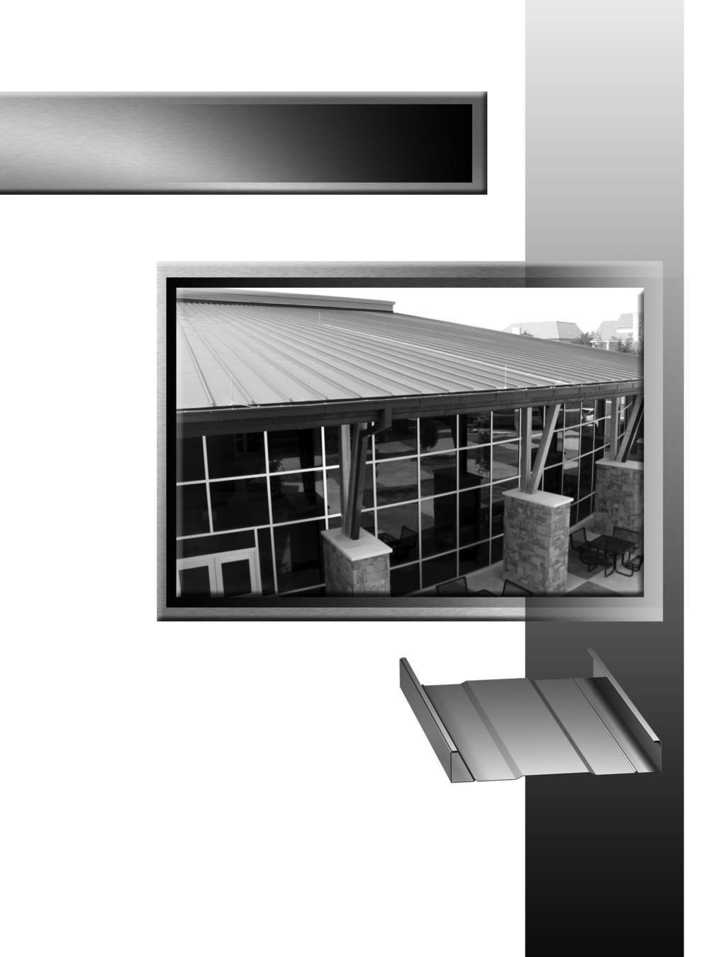
2 TABLE OF CONTENTS PAGE NUMBER: DETAIL DESCRIPTION A-1...TABLE OF CONTENTS A-2...GENERAL NOTES B-1...GENERAL INFORMATION C-1...EAVE DRIP DETAIL C-2...EAVE DRIP with GUTTER DETAIL C-3 & C-4...FIXED RIDGE DETAIL C-5 & C-6...FIXED HIGH EAVE DETAIL C-7 & C-8...FIXED HIGH-SIDE TIE-IN DETAIL C-9...FLOATING RAKE DETAIL C-10...FLOATING RAKE DETAIL (ALTERNATE) C-11...FLOATING SIDE-WALL TIE-IN DETAIL C-12 & C-13...VALLEY DETAIL C-14 & C-15...VALLEY DETAIL (ALTERNATE) C-16 & C-17...HIP DETAIL C-18...DEKTITE DETAIL C-19 thru C-23...CURB INSTALLATION DETAILS C-24 & C-25...TRIM LAP DETAILS A-1
3 GENERAL NOTES The details shown on the following pages are suggestions or guidelines for installing the 238T roof panel system. The installation details shown here are proven methods of construction, but they are not intended to cover all building requirements, designs or codes. The details may require changes or revisions due to individual project conditions. In addition, other details may be perfectly acceptable for use. Please contact McElroy Metal for assistance in determining if a detail is acceptable. Installation procedures shall be in accordance with the manufacturer's printed instructions, details or approved shop drawings. Installers should thoroughly familiarize themselves with all instructions prior to beginning the installation process. The designer/installer is responsible to ensure the following: That the details here meet the particular building requirements. Awareness of and allowance for expansion/contraction of the roof panels. That adequate water tightness is maintained. That a proper uniform substructure is used to avoid panel distortion and that the substructure meets necessary code requirements. That all supporting members have been examined and are straight, level and plumb. McElroy Metal can provide all flashings and accessories shown in the installation drawings unless noted otherwise. Panels, flashing and trim shall be installed true and in proper alignment with any exposed fasteners equally spaced for the best appearance. Sealant shall be field applied on a clean, dry surface. Some field cutting and fitting of panels and flashings is to be expected and to be considered a part of normal installation work. Workmanship shall be of the best industry standards and with installation performed by experienced metal craftsmen. Oil canning of metal panels is inherent in the product and is not a cause for rejection. Plank or Striated panels are recommended as to reduce the appearance of oil canning. Contents of this manual are subject to change without notice. To confirm this book is the most current copy, please visit McElroy Metal's website at Optional details can also be found on our website. A-2

4 GENERAL INFORMATION SEAM ENGAGEMENT BEFORE SEAMING SEAM CAP WITH CONTINUOUS FACTORY SEALANT (2) BEADS 238T PANEL ATTENTION READ THE SEAMER INFORMATION THOROUGHLY BEFORE STARTING THE SEAMING OPERATION. FAILURE TO ADHERE TO THESE INSTRUCTIONS MAY RESULT IN PERSONAL INJURY AND DAMAGE TO THE SEAMER AND/OR PANELS. THE ERECTOR WILL BE HELD LIABLE FOR ANY COSTS INCURRED FOR REPLACEMENT OR REPAIR. PRE-SEAMING INFORMATION 1. Locate seamer box. Check to make sure you received an electric seamer, parts box, return shipping label and an information booklet. If not, please call our Technical Services Department. (Hand Seamers must be rented.) 2. Locate power source and check against power requirements in the information booklet. 3. Check seams for proper engagement. 4. Clean dirt, debris and excess sealant from seams and panel surfaces to avoid interfering with the seaming operation. HAND SEAMING OPERATION!!!ATTENTION!!! It is critical that the panel seams are crimped and folded before using the electric seamer. Failure to follow these guidelines will result in damaged seams. To begin seaming, set the hand seamer on the seam. Align the edge of the hand seamer about one to two inches pass the edge of the panel. Crimp the panel 3 to 4 times along the seam for a total of 12" at the eave and 5 or 6 times along the seam for a total of 18" at the ridge and then at every clip. AFTER SEAMING NOTE: Mechanical seamers and hand seamers are available for rental through McElroy's approved seamer supplier at the following website. Go to: If a panel or seam becomes damaged, the installer can rent a "de-seamer" through the same website listed above. CAUTION: The use of any seaming machine or tools other than that recommended by the manufacturer, may damage the panels, void all warranties and will void all engineering data. B-1
5 EAVE DRIP DETAIL #14-10 X 1 1/2" HWH TYPE A FASTENER (@ 1'-0" O.C.) #14-10 X 1 1/2" HWH TYPE A FASTENERS (2 PER CLIP) 3/16" DIA. BEAD OF BUTYL TUBE SEALANT FIELD NOTCH PANEL SEAM AND FOLD OVER END TABS MT-157: STANDARD EAVE/RAKE OFFSET FLASHING #9-15 X 1" HWH TYPE A FASTENER w/ WASHER (@ 2'-0" O.C.) (OPTIONAL DETAILS WITH NON- EXPOSED FASTENER CAN BE FOUND ON THE WEBSITE) HIGH TEMP. PEEL & STICK UNDERLAYMENT PLYWOOD DECK WOOD FASCIA MT-157: STANDARD EAVE/RAKE OFFSET FLASHING NOTES: 1. MT-157 (Standard Eave/Rake Offset Flashing) to run from out of wall to out of wall. 2. Attach MT-157 (Standard Eave/Rake Offset Flashing) to decking with #14-10 x 1 1/2" HWH Type A 1'-0" O.C. 3. Attach MT-157 (Standard Eave/Rake Offset Flashing) to the Wood Fascia with #9-15 x 1" HWH Type A Fastener with 2'-0" O.C. 4. Trim pieces lap 2". Apply 3/32" x 3/8" Butyl Tape or Butyl Tube Sealant in trim laps. 5. Place a 3/16" Dia. Bead of Butyl Tube Sealant to leading edge of 238T panel. 6. Field Notch panel seam and fold over end tabs of panels. 238T SEAM CAP FIELD NOTCH PANEL SEAM AND FOLD OVER END TABS #14-10 X 1 1/2" HWH TYPE A FASTENERS (2 PER CLIP) MT-157: STANDARD EAVE/RAKE OFFSET FLASHING 3/16" DIA. BEAD OF BUTYL TUBE SEALANT #14-10 X 1 1/2" HWH TYPE A FASTENER (@ 1'-0" O.C.) #9-15 X 1" HWH TYPE A FASTENER w/ WASHER (@ 2'-0" O.C.) (OPTIONAL DETAILS WITH NON- EXPOSED FASTENER CAN BE FOUND ON THE WEBSITE) HIGH TEMP. PEEL & STICK UNDERLAYMENT PLYWOOD DECK WOOD FASCIA C-1
6 EAVE DRIP w/ GUTTER DETAIL #14-10 X 1 1/2" HHA TYPE A FASTENER (@ 1'-0" O.C.) 3/16" DIA. BEAD OF BUTYL TUBE SEALANT FIELD NOTCH PANEL SEAM AND FOLD OVER END TABS MT-157: STANDARD EAVE/RAKE OFFSET FLASHING #9-15 X 1" HWH TYPE A FASTENER (1 PER STRAP) POP RIVET (2 PER STRAP) #14-10 X 1 1/2" HWH TYPE A FASTENERS (2 PER CLIP) HIGH TEMP PEEL & STICK UNDERLAYMENT PLYWOOD DECK MT-67: GUTTER STRAP 3/32" X 1" ROLL TAPE SEALANT (CONT. ALONG EAVE) MT-61: BOX GUTTER DOWNSPOUT WOOD FASCIA MT-61: GUTTER MT-157: STANDARD EAVE/RAKE OFFSET FLASHING NOTES: 1. MT-157 (Standard Eave/Rake Offset Flashing) and MT-61 (Box Gutter) to run from out of wall to out of wall 2. Apply a continuous bead of 3/32" x 1" Roll Tape Sealant to the inside vertical leg of the MT-61 (Gutter). Attach MT-67 (Gutter Straps) to Gutter with (2) Pop Rivets as shown in detail. 3. Attach MT-157 (Standard Eave/Rake Offset Flashing) to decking with #14-10 x 1 1/2" HWH Type A 1'-0" O.C. Slide vertical leg of Gutter behind MT-157 (Standard Offset Eave Flashing) and fasten through MT-67 (Gutter Strap), MT-157 (Standard Eave/Rake Offset Flashing), Tape Sealant and Gutter with #9-15 x 1" HWH Type A Fastener into Fascia Board required Gutter Strap Spacing. 4. Trim pieces lap 2". Apply 3/32" x 3/8" Butyl Tape or Butyl Tube Sealant in trim laps. 5. Place a 3/16" Dia. Bead of Butyl Tube Sealant to leading edge of 238T panel. 6. Field Notch panel seam and fold over end tabs of panels. SEAM CAP 3/16" DIA. BEAD OF BUTYL TUBE SEALANT MT-61: GUTTER MT-67: GUTTER STRAP (@ 2'-0" O.C.) POP RIVET (2 PER STRAP) #9-15 X 1" HWH TYPE A FASTENER (1 PER GUTTER STRAP) HIGH TEMP. PEEL & STICK UNDERLAYMENT PLYWOOD DECK FASTENER (2 PER CLIP) #14-10 X 1 1/2" HHA TYPE A FASTENER (@1'-0" O.C.) MT-157: STANDARD EAVE/RAKE OFFSET FLASHING 3/32" X 1" ROLL TAPE SEALANT (CONT. ALONG EAVE) FASCIA BOARD C-2
7 FIXED RIDGE DETAIL MT-2: RIDGE CAP 1/4-14 X 1 1/4" HWH TEK2 OR ZAC FASTENERS (2 PER TAB AT EACH CLIP. WASHER OR ZAC FASTENERS ARE ACCEPTABLE) 1/4-14 X 7/8" LAP TEK FASTENERS (@ 0'-6" O.C.) FIELD FOLD PAN OF PANEL 3/32" X 1" ROLL TAPE SEALANT (FILL ANY VOIDS WITH BUTYL TUBE SEALANT) MT-38: STANDARD OFFSET CLEAT PLYWOOD DECK FASTENERS (2 PER CLIP) OUTSIDE CLOSURE W/ 3/16" DIA. BEAD OF URETHANE SEALANT (BOTTOM AND SIDES) MT-38: STANDARD OFFSET CLEAT MT-2: RIDGE CAP NOTES: 1. MT-2 (Ridge Cap) and MT-38 (Standard Offset Cleat) to run from out of wall to out of wall. 2. Using a panning tool, fold up the pan of the panel at the ridge. 3. Install 238T panels and apply a 3/16" Dia. bead of Urethane Tube Sealant in the pan of the panel and up the the vertical legs where the foam closure will be placed. 4. Install Metal Closure Cover over the Foam Closure and secure to panel with (2) 1/4-14 x 1 1/14" HWH Tek2 or ZAC Fasteners, making sure to fasten through the clip to provide fixed point. 5. MT-2 (Ridge Cap) laps 2". Apply 3/32" x 1" Butyl Tape and Pop Rivet trims to MT-38 (Standard Offset Cleat with Pop Rivets at Laps. C-3
8 FIXED RIDGE DETAIL MT-2: RIDGE CAP 1/4-14 X 7/8" LAP TEK FASTENER (@ 0'-6" O.C.) MT-38: STANDARD OFFSET CLEAT 3/32" X 1" ROLL TAPE SEALANT (FILL ANY VOIDS WITH BUTYL TUBE SEALANT) OUTSIDE CLOSURE W/ 3/16" DIA. BEAD OF URETHANE SEALANT (BOTTOM AND SIDES) FIELD PAN PANELS FASTENERS (2 PER CLIP) PLYWOOD DECK MT-38: STANDARD OFFSET CLEAT MT-2: RIDGE CAP NOTES: 1. MT-2 (Ridge Cap) and MT-38 (Standard Offset Cleat) to run from out of wall to out of wall. 2. Using a panning tool, fold up the pan of the panel at the ridge. 3. Install 238T panels and apply a 3/16" Dia. bead of Urethane Tube Sealant in the pan of the panel and up the the vertical legs where the foam closure will be placed. 4. Install Metal Closure Cover over the Foam Closure and secure to panel with (2) 1/4-14 x 1 1/14" HWH Tek2 or ZAC Fasteners, making sure to fasten through the clip to provide fixed point. 5. MT-2 (Ridge Cap) laps 2". Apply 3/32" x 1" Butyl Tape and Pop Rivet trims to MT-38 (Standard Offset Cleat with Pop Rivets at Laps. C-4
9 FIXED HIGH EAVE DETAIL 3/32" X 1" ROLL TAPE SEALANT (FILL ANY VOIDS WITH BUTYL TUBE SEALANT) 1/4-14 X 7/8" LAP TEK FASTENERS (@ 1'-0" O.C.) 43D POP RIVETS (@ 0'-6" O.C.) 3/32" X 1" ROLL TAPE SEALANT (CONT. ALONG TOP OF STANDARD OFFSET CLEAT) OUTSIDE CLOSURE W/ 3/16" DIA. BEAD OF URETHANE SEALANT (BOTTOM AND SIDES) MT-38: STANDARD OFFSET CLEAT MT-25: HIGH EAVE TRIM 1/4-14 X 1 1/4" HWH TEK2 OR ZAC FASTENERS (2 PER TAB AT EACH CLIP. WASHER OR ZAC FASTENERS ARE ACCEPTABLE) FIELD FOLD PAN OF PANEL MT-156: RAKE SUPPORT CLEAT #10-12 X 1" TYPE A PANCAKE HEAD FASTENER (@ 1'-0" O.C.) FASCIA BOARD PLYWOOD DECK FASTENERS (2 PER CLIP) MT-156: RAKE SUPPORT CLEAT MT-38: STANDARD OFFSET CLEAT MT-25: HIGH EAVE TRIM NOTES: 1. MT-25 (High Eave Trim), MT-156 (Rake Support Cleat) and MT-38 (Standard Offset Cleat) to run from out to out of building. 2. Attach MT-156 (Rake Support Cleat) to fascia board with #10-12 x 1" Type A Pancake Head Fasteners at 1'-0" O.C. 3. Apply a 3/16" Dia. bead of Urethane Sealant to the pan and up the vertical legs of the panel where the Foam Outside Closure will be placed. Install Metal Closure Cover over Foam Outside Closure and attach to panels and clip with (2) 1/4-14 x 1 1/4" HWH Tek2 or ZAC Fasteners to provide a fixed point. Attach 1/4" Offset Cleat to Outside Closures with 1/4-14 x 7/8" Lap Tek fasteners at 1'-0" O.C. 4. Apply a continuous line of 3/32" x 1" Roll Tape Sealant to the top flange of the MT-38 (Standard Offset Cleat). 5. High Eave Trim to lap 2". Apply 3/32" x 3/8" Butyl Tape or Butyl Tube Sealant in trim laps and Pop Rivet flashing. Offset Cleat will butt joint. C-5
10 FIXED HIGH EAVE DETAIL MT-25: HIGH EAVE TRIM 43D POP RIVETS 0'-6" O.C.) 3/32" X 1" ROLL TAPE SEALANT (CONT. ALONG TOP OF STANDARD OFFSET CLEAT) 1/4-14 X 7/8" LAP TEK FASTENERS (@ 1'-0" O.C.) MT-156: RAKE SUPPORT CLEAT MT-38: STANDARD OFFSET CLEAT 3/32" X 1" ROLL TAPE SEALANT (FILL ANY VOIDS WITH BUTYL TUBE SEALANT) OUTSIDE CLOSURE W/ 3/16" DIA. BEAD OF URETHANE SEALANT (BOTTOM AND SIDES) FIELD FOLD PAN OF PANEL FASCIA BOARD FASTENERS (2 PER CLIP) PLYWOOD DECK MT-156: RAKE SUPPORT CLEAT MT-38: STANDARD OFFSET CLEAT MT-25: HIGH EAVE TRIM NOTES: 1. MT-25 (High Eave Trim), MT-156 (Rake Support Cleat) and MT-38 (Standard Offset Cleat) to run from out to out of building. 2. Attach MT-156 (Rake Support Cleat) to fascia board with #10-12 x 1" Type A Pancake Head Fasteners at 1'-0" O.C. 3. Apply a 3/16" Dia. bead of Urethane Sealant to the pan and up the vertical legs of the panel where the Foam Outside Closure will be placed. Install Metal Closure Cover over Foam Outside Closure and attach to panels and clip with (2) 1/4-14 x 1 1/4" HWH Tek2 or ZAC Fasteners to provide a fixed point. Attach 1/4" Offset Cleat to Outside Closures with 1/4-14 x 7/8" Lap Tek fasteners at 1'-0" O.C. 4. Apply a continuous line of 3/32" x 1" Roll Tape Sealant to the top flange of the MT-38 (Standard Offset Cleat). 5. High Eave Flashing to lap 2". Apply 3/32" x 3/8" Butyl Tape or Butyl Tube Sealant in trim laps and Pop Rivet flashing. Offset Cleat will butt joint. C-6
11 FIXED HEADWALL DETAIL REGLET MT-35: STANDARD HEAD-WALL TRIM 1/4-14 X 7/8" LAP TEK FASTENER (@ 0'-6" O.C.) MT-38: STANDARD OFFSET CLEAT POP RIVET (@ 0'-6" O.C.) 3/32" X 1" ROLL TAPE SEALANT (CONT. ALONG TOP OF STANDARD OFFSET CLEAT) OUTSIDE CLOSURE W/ 3/16" DIA. BEAD OF URETHANE SEALANT (BOTTOM AND SIDES) PLYWOOD DECK BUILDING LINE CAULKING FASTENER 3/32" X 1" ROLL TAPE SEALANT (FILL ANY VOIDS WITH BUTYL TUBE SEALANT) FIELD FOLD PAN OF PANEL 1/4-14 X 1 1/4" HWH TEK2 OR ZAC FASTENERS (2 PER TAB AT EACH CLIP. WASHER OR ZAC FASTENERS ARE ACCEPTABLE) FASTENERS (2 PER CLIP) MT-38: STANDARD OFFSET CLEAT MT-35: STANDARD HEADWALL TRIM NOTES: 1. MT-35 (Standard Headwall Trim) and MT-38 (Standard Offset Cleat) to run from out to out of building. 2. Apply a 3/16" Dia. bead of Urethane Sealant to the pan and up the vertical legs of the panel where the Foam Outside Closure will be placed. Install Metal Closure Cover over Foam Outside Closure and attach to panels and clip with (2) 1/4-14 x 1 1/4" HWH Tek2 or ZAC Fasteners to provide a fixed point. 3. Apply a continuous line of 3/32" x 1" Roll Tape Sealant to the top flange of the Metal Outside Closure. Attach 1/4" Offset Cleat to Outside Closure with 1/4-14 x 7/8" Lap Tek Fasteners at 0'-6" O.C. 4. Apply a continuous line of 3/32" x 1" Roll Tape Sealant to the top flange of the Offset Cleat. 5. MT-35 (Standard Headwall Trim) to lap 2". Apply 3/32" x 3/8" Butyl Tape or Butyl Tube Sealant in trim laps and Pop Rivet flashing. MT-38 (Standard Offset Cleat) will butt joint. C-7
12 FIXED HEADWALL DETAIL CAULKING MT-35: STANDARD HEADWALL TRIM 1/4-14 X 7/8" LAP TEK FASTENER (@ 0'-6" O.C.) 43D POP RIVET (@ 0'-6" O.C.) REGLET FASTENER 3/32" X 1" ROLL TAPE SEALANT (FILL ANY VOIDS WITH BUTYL TUBE SEALANT) 3/32" X 1" ROLL TAPE SEALANT (CONT. ALONG TOP OF OFFSET CLEAT) MT-38: STANDARD OFFSET CLEAT OUTSIDE CLOSURE W/ 3/16" DIA. BEAD OF URETHANE SEALANT (BOTTOM AND SIDES) BULIDNG LINE FASTENERS (2 PER CLIP) WOOD BLOCKING PLYWOOD DECK MT-38: STANDARD OFFSET CLEAT MT-35: STANDARD HEADWALL TRIM NOTES: 1. MT-35 (Standard Headwall Trim) and MT-38 (Standard Offset Cleat) to run from out to out of building. 2. Apply a 3/16" Dia. bead of Urethane Sealant to the pan and up the vertical legs of the panel where the Foam Outside Closure will be placed. Install Metal Closure Cover over Foam Outside Closure and attach to panels and clip with (2) 1/4-14 x 1 1/4" HWH Tek2 or ZAC Fasteners to provide a fixed point. 3. Apply a continuous line of 3/32" x 1" Roll Tape Sealant to the top flange of the Metal Outside Closure. Attach 1/4" Offset Cleat to Outside Closure with 1/4-14 x 7/8" Lap Tek Fasteners at 0'-6" O.C. 4. Apply a continuous line of 3/32" x 1" Roll Tape Sealant to the top flange of the Offset Cleat. 5. MT-35 (Standard Headwall Trim) to lap 2". Apply 3/32" x 3/8" Butyl Tape or Butyl Tube Sealant in trim laps and Pop Rivet flashing. MT-38 (Standard Offset Cleat) will butt joint. C-8
13 FLOATING RAKE DETAIL 1/4-14 X 1 1/4" TEK2 ZAC FASTENER (@ 1'-0" O.C.) 3/32" X 1" TAPE SEALANT (CONT. ALONG LENGTH OF RAKE) 3/16" X 7/8" DOUBLE BEAD TAPE SEALANT (CONT. ALONG LENGTH OF RAKE) MT-183: RAKE TRIM 1/4-14 X 1 1/4" TEK2 ZAC FASTENER (@ 1'-0" O.C.) MT-SLOT-Z238: SPECIAL 16GA. SLOTTED ZEE #10-12 X 1" TYPE A PANCAKE HEAD FASTENER (@ 1'-0" O.C.) MT-156: RAKE SUPPORT CLEAT FASTENER (@ 1'-0" O.C.) WOOD FASCIA MT-183: RAKE TRIM MT-156: RAKE SUPPORT CLEAT NOTES: 1. MT-183 (Rake Trim), MT-156 (Rake Support Cleat) and MT-SLOT-Z238 (Special 16ga. Slotted Zee) to run from eave to ridge. 2. Attach MT-SLOT-Z238 (Special 16ga. Slotted Zee) to decking with #14-10 x 1 1/2" HWH Type A Fasteners at 1'-0" O.C. 3. Apply a continuous bead of 3/16" x 7/8" Double Bead Tape Sealant to the vertical leg of the 238T panel. Install 238T panel and hold in place on the Slotted Zee with clamps. Fasten panel to Slotted Zee with 1/4-14 x 1 1/4" Tek2 ZAC Fasteners at 1'-0" O.C. 4. Apply a continuous bead of 3/32" x 1" Roll Tape Sealant to the top of the Slotted Zee and attach MT-183 (Rake Trim) with 1/4-14 x 1 1/4" Tek2 ZAC Fasteners at 1'-0" O.C. 5. Trim pieces lap 2". Apply 3/32" x 3/8" Butyl Tape or Butyl Tube Sealant in trim laps and Fasten to trims. 3/32" X 1" TAPE SEALANT (CONT. ALONG LENGTH OF RAKE) MT-SLOT-Z238: SPECIAL 16GA. SLOTTED ZEE 3/16" X 7/8" DOUBLE BEAD TAPE SEALANT (CONT. ALONG LENGTH OF RAKE) 1/4-14 X 1 1/4" TEK2 ZAC FASTENER (@ 1'-0" O.C.) WOOD FASCIA 1/4-14 X 1 1/4" TEK2 ZAC FASTENER (@ 1'-0" O.C.) #10-12 X 1" TYPE A PANCAKE HEAD FASTENER (@ 1'-0" O.C.) MT-156: RAKE SUPPORT CLEAT FASTENER (@ 1'-0" O.C.) MT-183: RAKE TRIM C-9
14 FLOATING RAKE DETAIL (ALT.) 238T SEAM CAP FASTENERS (2 PER CLIP) #10-12 X 1" TYPE A PANCAKE HEAD FASTENER (@ 1'-0" O.C.) MT-31: STANDARD RAKE TRIM #10-12 X 1" TYPE A PANCAKE HEAD FASTENER (@ 1'-0" O.C.) MT-37 STANDARD CLEAT FASCIA BOARD MT-31: STANDARD RAKE TRIM MT-37: STANDARD CLEAT NOTES: 1. MT-31 (Rake Trim) and MT-37 (Standard Cleat) to run from eave to ridge. 2. Attach MT-37 (Standard Cleat) to Fascia Board with #10-12 x 1" Type A Pancake Head Fasteners at 1'-0" O.C. 3. Attach MT-31 (Rake Trim) to MT-37 (Standard Cleat) and fasten to Plywood Decking with #10-12 x 1" Type A Pancake Head Fasteners at 1'-0" O.C. 4. Field cut leading edge of panel and fold panel down T SEAM CAP #10-12 X 1" TYPE A PANCAKE HEAD FASTENER (@ 1'-0" O.C.) MT-31: STANDARD RAKE TRIM #10-12 X 1" TYPE A PANCAKE HEAD FASTENER (@ 1'-0" O.C.) MT-37: STANDARD CLEAT FASCIA BOARD C-10
15 FLOATING SIDE-WALL TIE-IN DETAIL CAULKING REGLET 1/4-14 X 1 1/4" TEK2 ZAC FASTENER (@ 1'-0" O.C.) BUILDING LINE FASTENER MT-34: STANDARD SIDE-WALL TRIM FLEXIBLE MEMBRANE 3/16" X 7/8" DOUBLE BEAD TAPE SEALANT (CONT. ALONG LENGTH OF RAKE) 1/4-14 X 1 1/4" TEK2 ZAC FASTENER (@ 1'-0" O.C.) MT-SLOT-Z238: SPECIAL 16GA. SLOTTED ZEE #14-10 X 1 1/2" HHA FASTENER (@ 1'-0" O.C.) FASCIA BOARD MT-34: STANDARD SIDE-WALL TRIM NOTES: 1. MT-34 (Standard Side-Wall Trim) to run from Eave to Ridge. 2. Attach MT-SLOT-Z238 (Special 16ga. Slotted Zee) to decking with #14-10 x 1 1/2" HWH Type A Fasteners at 1'-0" O.C. 3. Apply a continuous run of 3/16" x 7/8" Double Bead Tape Sealant to the vertical leg of the 238T panel. Install 238T panel and hold in place on the Slotted Zee with clamps. Fasten panel to Slotted Zee with 1/4-14 x 1 1/4" Tek2 Zac Fasteners at 1'-0" O.C. 4. Apply a continuous run of 3/32" x 1" Roll Tape Sealant to the top of the Slotted Zee and attch MT-34 (Standard Side-Wall Trim) with 1/4-14 x 1 1/4" Tek2 ZAC Fasteners at 1'-0" O.C. 5. Trim pieces lap 2". Apply 3/32" x 3/8" Butyl Tape or Butyl Tube Sealant in trim laps and Fasten to trims. BUILDING LINE CAULKING REGLET MT-34: STANDARD SIDE-WALL TRIM 1/4-14 X 1 1/4" TEK2 ZAC FASTENER (@1'-0" O.C.) FASTENER 1/4-14 X 1 1/4" TEK2 ZAC FASTENER (@ 1'-0" O.C.) FLEXIBLE MEMBRANE 3/32" X 1" TAPE SEALANT (CONT. ALONG LENGTH OF RAKE) MT-SLOT-Z238: SPECIAL 16GA. SLOTTED ZEE 3/16" X 7/8" DOUBLE BEAD TAPE SEALANT (CONT. TOP OF SLOTTED ZEE) WOOD BLOCKING C-11
16 VALLEY DETAIL MT-10: VALLEY TRIM 3/16" DIA. BEAD OF BUTYL TUBE SEALANT MT-11: VALLEY / WAVE CLIP HIGH TEMP. PEEL & STICK UNDERLAYMENT FASTENERS (2 PER CLIP) #10-12 X 1" TYPE A PANCAKE HEAD FASTENERS (@ 1'-0" O.C.) FIELD NOTCH PANEL SEAM AND FOLD OVER END TABS HIGH TEMP. PEEL & STICK UNDERLAYMENT MT-10: VALLEY TRIM MT-11: VALLEY / WAVE CLIP NOTES: 1. Install MT-10 (Valley Trim) from eave to ridge. MT-10 (Valley Trim) pieces lap 6". Place 3/32" x 1" Butyl Tape or a 3/16" Dia. bead of Butyl Tube Sealant in laps. 2. Cut panels at required bevel for valley condition. 3. Attach MT-11 (Valley / Wave Clip) with #10-12 x 1" Type A Pancake Head fasteners at 1'-0" O.C. C-12
17 VALLEY DETAIL 238T SEAM CAP MT-11: VALLEY / WAVE CLIPS HIGH TEMP. PEEL & STICK UNDERLAYMENT #10-12 X 1" TYPE A PANCAKE HEAD FASTENERS (@ 1'-0" O.C.) MT-10: VALLEY TRIM MT-10: VALLEY TRIM MT-11: VALLEY / WAVE CLIP NOTES: 1. Install MT-10 (Valley Trim) from eave to ridge. MT-10 (Valley Trim) pieces lap 6". Place 3/32" x 1" Butyl Tape or a 3/16" Dia. bead of Butyl Tube Sealant in laps. 2. Cut panels at required bevel for valley condition. 3. Attach MT-11 (Valley / Wave Clip) with #10-12 x 1" Type A Pancake Head fasteners at 1'-0" O.C. C-13
18 VALLEY DETAIL (ALT.) MT-8: VALLEY TRIM 3/16" DIA. BEAD OF BUTYL TUBE SEALANT 3/32" X 1" ROLL TAPE SEALANT (CONT. ALONG LENGTH OF VALLEY) MT-38: STANDARD OFFSET CLEAT HIGH TEMP. PEEL & STICK UNDERLAYMENT FASTENERS (2 PER CLIP) #10-12 X 1" TYPE A PANCAKE HEAD FASTENERS (@ 1'-0" O.C.) FIELD NOTCH PANEL SEAM AND FOLD OVER END TABS MT-8: VALLEY TRIM MT-38: STANDARD OFFSET CLEAT NOTES: 1. Install MT-8 (Valley Trim) from eave to ridge. MT-8 (Valley Trim) pieces lap 6". Place 3/32" x 1" Butyl Tape or a 3/16" Dia. bead of Butyl Tube Sealant in laps. 2. Cut panels at required bevel for valley condition. 3. Apply a continuous line of 3/32" x 1" Roll Tape Sealant up both sides of MT-8 (Valley Trim). 4. Install MT-38 (Standard Offset Cleat) with #10-12 x 1" Type A Pancake Head fasteners at 1'-0" O.C. C-14
19 VALLEY DETAIL 238T SEAM CAP MT-38: OFFSET CLEAT HIGH TEMP. PEEL & STICK UNDERLAYMENT #10-12 X 1" TYPE A PANCAKE HEAD FASTENERS (@ 1'-0" O.C.) 3/32" X 1" ROLL TAPE SEALANT (CONT. ALONG LENGTH OF VALLEY) MT-8: VALLEY TRIM MT-8: VALLEY TRIM MT-38: STANDARD OFFSET CLEAT NOTES: 1. Install MT-8 (Valley Trim) from eave to ridge. MT-8 (Valley Trim) pieces lap 6". Place 3/32" x 1" Butyl Tape or a 3/16" Dia. bead of Butyl Tube Sealant in laps. 2. Cut panels at required bevel for valley condition. 3. Apply a continuous line of 3/32" x 1" Roll Tape Sealant up both sides of MT-8 (Valley Trim). 4. Attach MT-38 (Standard Offset Cleat) with #10-12 x 1" Type A Pancake Head fasteners at 1'-0" O.C. C-15
20 HIP DETAIL FIELD FOLD PAN OF PANEL 3/32" X 1" ROLL TAPE SEALANT (CONT. ALONG TOP OF ZEE CLOSURES) MT-5: HIP CAP 1/4-14 X 7/8" LAP TEK FASTENERS (@ 0'-6" O.C.) MT-38: STANDARD OFFSET CLEAT FASTENERS (2 PER CLIP) FASTENERS (@ 1'-0" O.C.) 1/4-14 X 1 1/4" TEK2 ZAC FASTENERS (@ 0'-4" O.C.) MT-17: ZEE CLOSURE (CUT AND FOLD 1" TABS ON SIDES) (3/16" X 7/8" DOUBLE BEAD TAPE SEALANT ON SIDES AND BOTTOM) LOW EAVE PLATE (PRE-DRILL 5/16" DIA. 1'-0" O.C. MAX.) MT-17: ZEE CLOSURE MT-38: STANDARD OFFSET CLEAT MT-5: HIP CAP NOTES: 1. MT-5 (Hip Cap) to run from Eave to Ridge. MT-38 (Standard Offset Cleat) to run from Ridge to Eave. 2. Using a panning tool, fold up the pan of the panel at the Hip. 3. Install 238T panels as directed in this manual. 4. Cut individual Zee Closures with 1" Side Tabs from the MT-17 (Zee Closure). Apply a 3/16" x 7/8" Double Bead Tape Sealant to the bottom and sides of Zee Closures and install 2" down from end of panel. Fasten with 1/4-14 x 1 1/4" Tek2 ZAC fasteners at 0'-4" (Max.). 5. MT-5 (Hip Cap) laps 2". Apply 3/32" x 1" Butyl Tape and Pop Rivet trims to MT-38 (Standard Offset Cleat with Pop Rivets at Laps. C-16
21 HIP DETAIL MT-5: HIP CAP 1/4-14 X 7/8" LAP TEK FASTENER (@ 1'-0" O.C.) 238T SEAM CAP MT-38: STANDARD OFFSET CLEAT 3/32" X 1" ROLL TAPE SEALANT (CONT. ALONG TOP OFFSET CLEAT) 1/4-14 X 1 1/4" TEK2 ZAC FASTENERS (@ 0'-4" O.C.) #14-10 X 1 1/2" HWH TYPE A FASTENERS (@ 1'-0" O.C.) FASTENERS (2 PER CLIP) MT-17: ZEE CLOSURE (CUT AND FOLD 1" TABS ON SIDES. 3/16" X 7/8" DOUBLE BEAD TAPE SEALANT ON SIDES AND BOTTOM) 3/16" X 7/8" DOUBLE BEAD TAPE SEALANT (CONT. ALONG TOP OF CLOSURES) LOW EAVE PLATE (PRE-DRILL 5/16" DIA. 1'-0" O.C. MAX.) PLYWOOD DECK MT-17: ZEE CLOSURE MT-38: STANDARD OFFSET CLEAT MT-5: HIP CAP NOTES: 1. MT-5 (Hip Cap) to run from Eave to Ridge. MT-38 (Standard Offset Cleat) to run from Ridge to Eave. 2. Using a panning tool, fold up the pan of the panel at the Hip. 3. Install 238T panels as directed in this manual. 4. Cut individual Zee Closures with 1" Side Tabs from the MT-17 (Zee Closure). Apply a 3/16" x 7/8" Double Bead Tape Sealant to the bottom and sides of Zee Closures and install 2" down from end of panel. Fasten with 1/4-14 x 1 1/4" Tek2 ZAC fasteners at 0'-4" (Max.). 5. MT-5 (Hip Cap) laps 2". Apply 3/32" x 1" Butyl Tape and Pop Rivet trims to MT-38 (Standard Offset Cleat with Pop Rivets at Laps. C-17
22 DEKTITE DETAIL DEKTITE PIPE BOOT VENT PIPE STAINLESS STEEL HOSE CLAMP 1/4-14 X 7/8" LAP TEK ZAC FASTENERS (@ 0'-2" O.C.) BUTYL TUBE SEALANT (CONT. 3/16" DIA. BEAD AROUND DEKTITE) NOTES: 1. Cut hole in panel 1" larger than pipe diameter. If installing over a solid substrate, over-cut hole in substrate so fastener do not pin system from thermal movement. 2. Cut hole in top of Dektite Boot so that it fits snuggly around pipe. Apply a 3/16" Dia. bead of Tube Butyl sealant around the base flange of boot. Secure to panel with 1/4-14 x 7/8" Lap Tek ZAC fasteners 2" O.C. 3. Dektite boot MUST fit in pan of panel. Do not fasten to standing seams. DEKTITE PIPE BOOT 1/4-14 X 7/8" LAP TEK ZAC FASTENERS (@ 0'-2" O.C.) VENT PIPE STAINLESS STEEL HOSE CLAMP BUTYL TUBE SEALANT (CONT. 3/16" DIA. BEAD AROUND DEKTITE) 238T SEAM CAP C-18
23 ROOF CURB DETAIL STEP #1 C-19
24 ROOF CURB DETAIL ALL-WELDED ALUMINUM CURB 3/16" X 7/8" DOUBLE BEAD TAPE SEALANT BACK-UP CHANNEL STEP #2 FASTENER (2 PER CLIP) C-20
25 ROOF CURB DETAIL 3/16" X 7/8" DOUBLE BEAD TAPE SEALANT ALL-WELDED ALUMINUM CURB CLAMPS BACK-UP CHANNEL STEP #3 FASTENER (2 PER CLIP) C-21
26 ROOF CURB DETAIL ALL-WELDED ALUMINUM CURB 1/4-14 X 1 1/4" TEK2 ZAC FASTENERS (@ 0'-4" O.C.) 3/32" X 1" X 2" LONG PIECE OF ROLL TAPE SEALANT 3/16" X 7/8" DOUBLE BEAD TAPE SEALANT 3/16" DIA. BEAD OF BUTYL TUBE SEALANT 3/16" X 7/8" DOUBLE BEAD ROLL TAPE SEALANT BACK-UP CHANNEL FASTENER (2 PER CLIP) STEP #4 C-22
27 ROOF CURB DETAIL ALL-WELDED ALUMINUM CURB SEAM CAP 1/4-14 X 1 1/4" TEK2 ZAC FASTENERS (@ 0'-4" O.C.) ALL-WELDED ALUMINUM RIB CAP (FILL CAP 2/3's FULL WITH BUTYL TUBE SEALANT) BACK-UP CHANNEL FASTENER (2 PER CLIP) STEP #5 C-23
28 TYPICAL TRIM LAP DETAIL RAKE TRIM 3/32" X 3/8" ROLL TAPE SEALANT OR 3/16" DIA. BEAD OF TUBE BUTYL RAKE TRIM RAKE TRIM 43D POP RIVETS 3/8" OFFSET EAVE FLASHING 3/32" X 3/8" ROLL TAPE SEALANT OR 3/16" DIA. BEAD OF TUBE BUTYL SEAM CAP SEAM CAP STANDARD EAVE/RAKE OFFSET FLASHING PLACE A SMALL BLOB OF BUTYL TUBE SEALANT ON SEAM CAP ABOUT 2" DOWN FROM END OF SEAM CAP ZEE CLOSURE STANDARD EAVE/RAKE OFFSET FLASHING 3/32" X 3/8" ROLL TAPE SEALANT OR 3/16" DIA. BEAD OF TUBE BUTYL SLOPE ZEE CLOSURE ZEE CLOSURE SLOPE ZEE CLOSURE NOTE: 1. Apply 3/32" x 3/8" Roll Tape Sealant or a 3/16" Dia. bead of Tube Butyl 1 1/2" back from the edge of the trim. Also, apply a piece of tape sealant or bead of Tube Butyl as a Pigtail to completely seal joint. 2. Notch the hems on the upper trim piece 2" so that the trim will fit flat in the lap joint. 3. Secure trim laps with Pop Rivets as shown above. C-24
29 TYPICAL TRIM LAP DETAIL 3/32" X 1" ROLL TAPE SEALANT OR 3/16" DIA. BEAD OF TUBE BUTYL RIDGE OR HIP FLASHING RIDGE OR HIP FLASHING RIDGE OR HIP FLASHING RIDGE OR HIP FLASHING POP RIVET (2 PER LAP AND FASTEN TO CLOSURE) VALLEY TRIM w/o CLEAT 3/32" X 1" ROLL TAPE SEALANT OR 3/16" DIA. BEAD OF TUBE BUTYL VALLEY TRIM w/o CLEAT SLOPE VALLEY TRIM w/o CLEAT SLOPE VALLEY TRIM w/o CLEAT NOTE: 1. Apply 3/32" x 1" Roll Tape Sealant or a 3/16" Dia. bead of Tube Butyl 1 1/2" back from the edge of the trim. 2. Notch the hems on the upper trim piece 2" so that the trim will fit flat in the lap joint. 3. Secure trim laps with Pop Rivets as shown above. C-25
30
 TremLock T-138 INSTALLATION MANUAL T-138 www.tremcoroofing.com 3735 Green Road Beachwood, Ohio 44122 1.800.852.6013 50 Beth Nealson Drive Toronto, Ontario M4H 1M6 1.800.668.9879 7241 6/8/18 TABLE OF CONTENTS
REGAL. Installation Manual
 REGAL Installation Manual General Information The details shown on the following pages are suggestions or guidelines for installing the Regal system. The installation details shown here are proven methods
TABLE OF CONTENTS A-1...TABLE OF CONTENTS A-2...GENERAL NOTES B-1 & B-2...GENERAL INFORMATION (FASTENER PATTERNS)
") FW SERIES TABLE OF CONTENTS PAGE NUMBER: DETAIL DESCRIPTION A-1...TABLE OF CONTENTS A-2...GENERAL NOTES B-1 & B-2...GENERAL INFORMATION (FASTENER PATTERNS) DETAILS C-1...SIMPLE BASE DETAIL with 1 1/2"
FW SERIES TABLE OF CONTENTS PAGE NUMBER: DETAIL DESCRIPTION A-1...TABLE OF CONTENTS A-2...GENERAL NOTES B-1 & B-2...GENERAL INFORMATION (FASTENER PATTERNS) DETAILS C-1...SIMPLE BASE DETAIL with 1 1/2"
TABLE OF CONTENTS A-1...TABLE OF CONTENTS A-2...GENERAL NOTES B-1 & B-2...GENERAL INFORMATION
 TABLE OF CONTENTS PAGE NUMBER: DETAIL DESCRIPTION A-1...TABLE OF CONTENTS A-2...GENERAL NOTES B-1 & B-2...GENERAL INFORMATION MATRIX DETAILS C-1...FASCIA/SOFFIT DETAIL with ANGLE C-2...BUILDING/SOFFIT
TIOGA Table of Contents
 Table of Contents TABLE OF CONTENTS Product Data Sheet...2 Engineering Data...3 General Information...4 Handling...5 Roof Preparation...5 Fastening Recommendations...6 Field Cutting...7 Touch-up Paint...7
ProSnap 100 STANDARD DETAILS
 ProSnap 100 OVER WOOD DECK STANDARD DETAILS Austin - Headquarters/Sales Office 830 Sagebrush Drive Austin, TX 78758 (512) 452-1515 (800) 428-7412 Fax (512) 833-7499 www.ctmrs.com email: info@ctmrs.com
Ekoroof LiteTile Dimensions
 Ekoroof LiteTile Dimensions 7 3 3.5 Height 40 Width 20 Length Weight per Panel: 3 kg / 6.61 lbs 2 2 Area per panel 800 in / 5.55 ft 2 Panels per Square: 20 (including overlap, for a 100 ft covered area)
METAL ROOFING INSTALLATION GUIDE
 METAL ROOFING INSTALLATION GUIDE STANDING SEAM ROOFING PANELS Horizon 16 and Climaguard 16 Regardless of whether your roofing project is a new installation or a re-roof, and whether your building is residential,
TABLE OF CONTENTS A. PBR
 TABLE OF CONTENTS A. PBR Panel 1. PBR Panel Architect/Engineer Information....................................... 2 2. PBR Panel UL 90 Requirements............................................... 3 3. PBR
Installation Guide. Step 3. Valley Flashing. Step 7. Transition Flashings and Accessories. Step 6. Hip and Ridge Installation
 Step 7. Transition s and Accessories Step 3. Valley Step 6. Hip and Ridge Installation Step 2. Rake Trim Step 5. Installing the Shingles Step 1. Eave Starter Installation Step 4. Endwall s Installation
900 SERIES WALL PANELS
 CI-DS-01-900 CI-PP-01-900 CI-PJ-01-900 CI-PJ-02-900 CI-PJ-03-900 CI-BS-01-900 CI-BS-02-900 CI-BS-03-900 CI-BS-04-900 CI-BS-05-900 CI-OC-01-900 CI-OC-02-900 CI-IC-01-900 CI-FO-01-900 CI-FO-02-900 CI-FO-03-900
Tuff-Rib Install Guide
 Install Guide bestbuymetalroof.com Page 2 of 27 Page 3 of 27 1. Page 4 2. a. Installation Guide b. Panel Squaring Pages 5, 6 Pages 7, 8 3. Pages 9, 10 4. a. Fascia (optional) b. Eave / 1.5x3.5 Angle c.
900 SERIES PANEL SHEET INDEX STAGGERED ENDLAP STAGGERED MALE LEG AT ENDLAP CONTINUOUS FEMALE ENDLAP INSTALLATION SEQUENCE CI-WR
 900 SERIES PANEL CI-DS-01-900 CI-PJ-01-900 CI-PJ-02-900 CI-EL-01-900 CI-EL-02-900 CI-EL-03-900 CI-EL-04-900 CI-EL-05-900 CI-EL-06-900 CI-EL-07-900 CI-EL-08-900 CI-RD-01-900 CI-RD-02-900 CI-RD-03-900 CI-EV-01-900
Best Buy Metals Toll Free / Phone / Fax
 DETAIL MANUAL for Vertical Seam Best Buy Metals Toll Free 1-800-728-4010 / Phone 423-479-6382 / Fax 423-728-3066 www.bestbuymetals.com Vertical Seam Roofing Panels Fig. 2 Vertical Seam Has 1-3/4" high
KS SERIES - VERTICAL INSTALLATION
 CS-DS-01-KSV CS DISCLAIMER CS-PJ-01-KSV KS42SL EXPANDED PANEL JOINT CS-PJ-02-KSV KS42SL ENGAGED PANEL JOINT CS-PJ-03-KSV KS45SL EXPANDED PANEL JOINT CS-PJ-04-KSV KS45 FLAT ENGAGED PANEL JOINT CS-PJ-05-KSV
MAXIMUM PANEL ATTACHMENT FASTENER SPACING IS 24" O.C. ALL FASTENERS TO PENETRATE WOOD 3/4" MIN. AND METAL FRAMING 1/2" MIN.
 PLYWOOD SHEATHING DMI SOFFIT PANEL #10-13 GP PANCAKE HEAD (JC) - J CLOSURE (LC) - L CLOSURE #9-15 X 1 1/2" WOODZAC GP APPROVED MOISTURE BARRIER SOFFIT TO WALL PANEL WPRP-H-01-00 APPROVED MOISTURE BARRIER
Table of Contents. Installation Guide for Profile with Hidden Fasteners 3. Installation Steps 4, 5. Prestige Series Moldings 6, 7. Other Accessories 8
 1 Table of Contents Page(s) Installation Guide for Profile with Hidden Fasteners 3 Installation Steps 4, 5 Prestige Series Moldings 6, 7 Other Accessories 8 Trims & Accessories 9 Eave Starters 10 Gableboards
Horizon-Loc. Installation Details 16" COVERAGE C GUID_INSTL_HLOC_160606
 Horizon-Loc Installation Details ¾" 1" 4" 16" COVERAGE D C GUID_INSTL_HLOC_160606 INDEX Information in the catalog may vary by plant location. Please call your salesperson to verify product availability.
DETAIL MANUAL for Standing Seam / Image II
 DETAIL MANUAL for Standing Seam / Image II Best Buy Metals Toll Free 1-800-728-4010 / Phone 423-479-6382 / Fax 423-728-3066 www.bestbuymetals.com Best Buy Metals Standing Seam Roofing Panels Fig. 2 Standing
SLATE & SHINGLE INSTALLATION
 EAVE EDGE Apply a small strip of roofing paper to the bottom of eave. Eave flashing is attached to substrate with roofing nails every 9". Install underlayment over entire roof. (See Fig. 1) PAGE 1 Bend
eco-shake INSTALLATION INSTRUCTION
 1 eco-shake INSTALLATION INSTRUCTION NOTE: Shuffling the eco-shakes during installation may be necessary to obtain a uniform color throughout the roof. Due to the natural wood content in the ecoshakes,
Tuff-Rib. Installation Manual. Nationwide supplier of quality metal roofing. Toll-Free (800) S. Lee Hwy. Cleveland, TN 37311
 S. Lee Hwy. Cleveland, TN 37311") Installation Manual Nationwide supplier of quality metal roofing. 65 S. Lee Hwy. Cleveland, TN 7.. www.bestbuymetals.com Toll-Free (800) 78-00 IMPORTANT NOTICE This manual contains suggestions and guidelines
Installation Manual Nationwide supplier of quality metal roofing. 65 S. Lee Hwy. Cleveland, TN 7.. www.bestbuymetals.com Toll-Free (800) 78-00 IMPORTANT NOTICE This manual contains suggestions and guidelines
SECTION SHEET METAL FLASHING AND TRIM
 SECTION 07620 PART 1 - GENERAL 1.1 SUMMARY A. Section Includes: 1. Formed roof drainage sheet metal fabrications. 2. Formed low-slope roof sheet metal fabrications. 1.2 SUBMITTALS A. Shop Drawings: Show
401 SW 33rd Ave Ocala, FL
 401 SW 33rd Ave Ocala, FL 34474 352-622-1035 www.metalroofingofocala.com Table of Contents Panels...Pg.1 Ultra Rib Trim...Pg.2-4 PBR Trim...Pg.5-6 5V Trim...Pg.7-9 TCM-Lok...Pg.10-11 Insulation/Ventilation:
CertainTeed. Shake / Slate Installation Guide
 CertainTeed Shake / Slate Installation Guide Table of Contents System Components... 2 General Conditions, Safety and Roof Preparations... 3... 4 Eave/Drip Edge... 5 Inner Gable... 6 Outer Gable... 7 Open
important notice This manual contains suggestions and guidelines on how to install the subject Quality Metals
 ml-200 important notice This manual contains suggestions and guidelines on how to install the subject Quality Metals time without incurring any obligations. To insure you have the latest information available,
DW HORIZONTAL INSTALLATION
 AR-PJ-01-DW2H 2" HORIZONTAL PANEL JOINT AR-PJ-02-DW2H 2" VERTICAL PANEL JOINT AR-PJ-03-DW2H 3" HORIZONTAL PANEL JOINT AR-PJ-04-DW2H 3" VERTICAL PANEL JOINT AR-PJ-05-DW2H CUSTOM REVEAL AR-PJ-06-DW2H DW-2000S
MetroCOTTAGE Shingle
 Batten-less Installation Sept. 14, 2017 INSTALLATION WARNING! These install details are provided to demonstrate a recommended installation method for Metro Roof panels and accessories. used in the United
Table of Contents Light Gauge Metal Roof & Wall Panels
 Table of Contents Light Gauge Metal Roof & Wall Panels Installation Guide for Delta Rib, Nor-Clad, Strata Rib & 2-1/2 Corrugated Introduction Important Notice Notes: April 2008 Minimum Recommended Tools
SHEET METAL FLASHING AND TRIM Christ on the Mountain
 SECTION 076200 - SHEET METAL FLASHING AND TRIM PART 1 - GENERAL 1.1 SUMMARY A. Section Includes: 1. Compatibly with the bumping of flashings and trim as identified in the Membrane Roofing Section 075000.
MasterRib. Installation Manual. July Toll-Free (888) MTL-ROOF. PO Box 229 Fayetteville, NC Rev.
 MTL-ROOF. PO Box 229 Fayetteville, NC Rev.") MasterRib Installation Manual July 010 PO Box 9 Fayetteville, NC 80.. www.unionmetalroofing.com Toll-Free (888) MTL-ROOF Rev. 7/10 IMPORTANT NOTICE This manual contains suggestions and guidelines on how
MasterRib Installation Manual July 010 PO Box 9 Fayetteville, NC 80.. www.unionmetalroofing.com Toll-Free (888) MTL-ROOF Rev. 7/10 IMPORTANT NOTICE This manual contains suggestions and guidelines on how
DW VERTICAL INSTALLATION
 AR-PJ-01-DW5V AR-PJ-02-DW5V AR-PJ-03-DW5V AR-PJ-04-DW5V AR-BS-01-DW5V AR-BS-02-DW5V AR-OC-01-DW5V AR-OC-02-DW5V AR-OC-03-DW5V AR-IC-01-DW5V AR-IC-02-DW5V AR-IC-03-DW5V AR-FO-01-DW5V AR-FO-02-DW5V AR-FO-03-DW5V
Features 24 ga steel or 26 ga steel. Colors available on standard or premium and metallic. 16 to 24 o.c. On site factory made.
 Strip Width Base Material Thickness Min Tensible Min Yield Coatings 16.00 to 24 in Steel.0128 to.027 in 52 - ksi 50 - ski Painted / Galvalume UL CONSTRUCTION NUMBERS: TGKX539 The Nail Strip 1.5 (NS-150)
FlexLoc. Technical/Installation Information
 Technical/Installation Information IMPORTANT NOTICE READ THIS MANUAL COMPLETELY PRIOR TO BEGINNING THE INSTALLATION OF THE FLEXLOC PANELS. ALWAYS INSPECT EACH AND EVERY PANEL AND ALL ACCESSORIES BEFORE
Table of Contents. Important Notices 3. Residential Roofing Application 4. Trims & Accessories 5. Trim Glossary 6, 7, 8. Estimating Material 9
 Table of Contents Page(s) Important Notices 3 Residential Roofing Application 4 Trims & Accessories 5 Trim Glossary 6, 7, 8 Estimating Material 9 Eave Trim Installation 10 Connecting Eavestarters 10 Gable
400 SERIES VERTICAL INSTALLATION
 CI-DS-01-400V CI-PJ-01-400V CI-PJ-02-400V CI-PJ-03-400V CI-BS-01-400V CI-BS-02-400V CI-BS-03-400V CI-BS-04-400V CI-BS-05-400V CI-OC-01-400V CI-OC-02-400V CI-IC-01-400V CI-IC-02-400V CI-FO-01-400V CI-FO-02-400V
Tuff Rib Panel Installation Specifications
 Tuff Rib Panel Installation Specifications ROOF APPLICATION: Roof slope must be a minimum of a 2/12 pitch to use this product. For slopes lower than a 3/12 pitch, lap sealant is suggested on the side laps
BARRELL VAULT BATTENLESS
 i BARRELL VAULT BATTENLESS INSTALLATION GUIDE INSTALLATION NOTIFICATION The installation procedures demonstrated in this manual are recommended methods for the installation of the Gerard Barrel Vault battenless
KS42 MF SERIES - HORIZONTAL INSTALLATION
 CI-DS-01-KSMF H CI-PJ-01-KSMF H CI-PJ-02-KSMF H CI-PJ-03-KSMF H CI-PJ-04-KSMF H CI-PJ-05-KSMF H CI-PJ-06-KSMF H CI-PJ-07-KSMF H CI-PJ-08-KSMF H CI-PJ-09-KSMF H CI-PJ-10-KSMF H CI-PJ-11-KSMF H CI-PJ-12-KSMF
Slate Shingle Specifications
 Slate Shingle Specifications California Slate is a proud member of the Slate Roofing Contractors Association of North America, Inc. (SRCA) which publishes Section 07310 Slate Shingles setting forth architectural
Steel Roofing & Siding INSTALLATION GUIDE
 Steel Roofing & Siding INSTALLATION GUIDE Your Authorized Dealer is: WASHINGTON Auburn (800) 700-7228 WASHINGTON Spokane (866) 321-5954 www.nuraymetals.com CALIFORNIA Redlands (800) 806-8729 CONTENTS BEFORE
Inspire Slate Starter Piece Hip and Ridge. 13 1/2" Height: 13 ½" Width: 12" Squares/ Pallet. Bundles/ Square
 December 2017 Classic Slate Application Guidelines Only Basic Roofing Tools Required Hand fastened or fastened with a pneumatic nail gun Utility knife or a standard circular saw Tape measure, pry bar,
4. Metal roof jacks at penetrations and attachments
 - - - - - - - - - - - - - - - - - - - - - - - - - - - - - - - - - - - - - - - - - - - - - - - - - - - - - - - - - - - - - - - - - - - - - - SECTION 07 61 00 METAL SHINGLE ROOFING - - - - - - - - - - -
Dura-Lock Roof System
 DLR-14 Dura-Lock Roof System Assembly and Installation Instructions Read the instructions before starting the job. They explain the steps required to produce a finished product that will meet factory specifications.
PROVEN DEPENDABLE SUSTAINABLE
 B/SOFFIT FP CLIP 24" O.C. MAX SECTION "A-A" PLYWOOD SHEATHING #10-13 GP PANCAKE HEAD FASTENER 12" O.C. A B/SOFFIT A (JC) - J CLOSURE DMI WALL PANEL PLYWOOD SHEATHING SOFFIT TO WALL PANEL FR10-V-01-00 B/SOFFIT
Hugger Installation. Roof Hugger, LLC P: P.O. Box 1027 F: Odessa, FL
 RECEIVING MATERIALS: ROOF HUGGERS are typically placed on wood pallets 3-5 wide and approximately 10 long weighing up to 5,000 lbs. ROOF HUGGERS are shipped via closed van for LTL less than truckload quantities
MANUAL. Perma-Loc & Secure-Seam. Standing Seam Roofing Panels & Accessories. and guide to Town and Country Metals products
 DETAIL MANUAL and guide to Town and Country Metals products Perma-Loc & Secure-Seam Standing Seam Roofing Panels & Accessories Town & Country Metals, LLC 10 Progress Parkway Union, MO 63084 Town and Country
Inspire Aledora Slate Application Guidelines
 July 2014 Inspire Aledora Slate Application Guidelines Only Basic Roofing Tools Required Hand fastened or fastened with a pneumatic nail gun Utility knife or a standard circular saw Tape measure, pry bar,
Table of Contents. Notes to Designer/User Map of Typical Roof Conditions Fastener Placement Fastener Selection...
 Table of Contents Section Page Notes to Designer/User... 2-3 Map of Typical Roof Conditions... 4 Fastener Placement... 5 Fastener Selection... 6 Ridge/Hip Flashing... 7 Valley Flashing... 8 Eave Flashings...
TYPICAL FRAMING AND STITCH FASTENER PATTERNS FOR MAX-RIB PANELS
 TYPICAL AND PATTERNS FOR MAX-RIB S MAX-RIB (PATTERN #1) @ 1'-8" O.C. (MAX.) ROLL TAPE SEALANT @ SEAMS MAX-RIB @ 1'-8" O.C. (MAX.) ROLL TAPE SEALANT @ SEAMS MAX-RIB TRIM (PATTERN #3) NOTE: TAPE SEALANT
PBR Panel Installation Specifications
 4906 St. Stephens Rd. 5780 Hwy 90 W Eight Mile, Al 36613 Theodore, AL 36590 251 456 2254 251 653 1550 251 457 2254(F) 251 653 1514(F) PBR Panel Installation Specifications ROOF APPLICATION: Roof slope
ONDUVILLA. The Attractive Alternative to Shingles I N S T A L L A T I O N I N S T R U C T I O N S
 ONDUVILLA The Attractive Alternative to Shingles I N S T A L L A T I O N I N S T R U C T I O N S 1 INSTALLATION INSTRUCTIONS Even though ONDUVILLA is easy to install, it is important to read through these
DMI FR1511 PANEL (JC) - J CLOSURE DMI WALL PANEL SOFFIT TO WALL PANEL PROVEN DEPENDABLE SUSTAINABLE METAL ENVELOPE SYSTEMS SINCE 1988
 - J CLOSURE DMI WALL PANEL SOFFIT TO WALL PANEL PROVEN DEPENDABLE SUSTAINABLE METAL ENVELOPE SYSTEMS SINCE 1988") FP CLIP 24" O.C. MAX B/SOFFIT 5 1/2" SECTION "A-A" PLYWOOD SHEATHING #10-13 GP PANCAKE HEAD FASTENER 12" O.C. A B/SOFFIT A (JC) - J CLOSURE DMI WALL PANEL PLYWOOD SHEATHING SOFFIT TO WALL PANEL FR15-V-01-00
FP CLIP 24" O.C. MAX B/SOFFIT 5 1/2" SECTION "A-A" PLYWOOD SHEATHING #10-13 GP PANCAKE HEAD FASTENER 12" O.C. A B/SOFFIT A (JC) - J CLOSURE DMI WALL PANEL PLYWOOD SHEATHING SOFFIT TO WALL PANEL FR15-V-01-00
VENTED GABLE DETAIL ROOF PANEL GABLE FLASHING 24" C/C MAX. BUTYL SEALANT TAPE ROOF PURLIN FLASH AB-1, AB-2, AB-3, OR AB-4
 GABLE FLASHING FASTENER @ 24" C/C MAX. ROOF PURLIN BUTYL SEALANT TAPE FLASH AB-1, AB-2, AB-3, OR AB-4 FASTENER @ EVERY MAJOR RIB OR 12" C/C MAX. F-J TRIM FABRAL ALUMINUM SOFFIT FASTENER 24" C/C MAX. BUTYL
CROSSBAR RAFTER ISOMETRIC
 Super Sky Products' typical glazing system consists of glass panels or "lites" which are attached to the main framing members using extruded aluminum "retainers" or "pressure plates". These retainers are
METRO PANELS (EXPOSED
 METRO PANELS 001EX-METRO-PANELS.VSD STARTER EAVE Detail Metro V-Bat RISER METAL (1) PANELS (2) FASTENERS (5) BOTTOM ROW fastening 0.75in. (4) METRO RISER Metal, With Integral Batten Riser & Locator-Lip.
2 ½ Corrugated Panel Installation Specifications
 2 ½ Corrugated Panel Installation Specifications ROOF APPLICATION: Roof slope must be a minimum of a 2/12 pitch to use this product. When using this product butyl lap sealant is recommended for all slopes.
INSTALLATION GUIDE LEARN MORE AT DECRA.COM
 Villa Tile INSTALLATION GUIDE LEARN MORE AT DECRA.COM Table of Contents DECRA Villa Tile Roof Overview... 2 Introduction... 3 Safety... 3 Tools.... 3 Estimating Sheet... 3 Codes & Requirements... 3 Roof
Phone (662) Fax (662) DETAIL MANUAL. and guide to Reed s Metals products
 Fax (662) DETAIL MANUAL. and guide to Reed s Metals products") Phone (662) 869-7797 www.reedsmetals.com Fax (662) 869-7799 DETAIL MANUAL and guide to Reed s Metals products Perma-Loc & Secure-Seam Standing Seam Roofing Panels & Accessories -1- Reed s Metals Standing
Phone (662) 869-7797 www.reedsmetals.com Fax (662) 869-7799 DETAIL MANUAL and guide to Reed s Metals products Perma-Loc & Secure-Seam Standing Seam Roofing Panels & Accessories -1- Reed s Metals Standing
Aluminum Clad Wood Window 1/2 Reinforced Field Mulling and Stacking Supplement
 Aluminum Clad Wood Window 1/2 Reinforced Field Mulling and Stacking Supplement 1 Aluminum Clad Wood Window 1/2 Reinforced Field Mulling and Stacking Supplement The following instructions are a supplement
installation guide Villa
 installation guide Villa Table of Contents Introduction............................. 2 Safety................................... 2 Tools.................................... 2 Codes & Requirements....................
Construction details: Master-C type profiles and joints:
 Construction details: Master-C type profiles and joints: Master-C 3g 32 mm. (1 1/4 ) 1000 mm. (39 3/8 ) outer face inner face 10.5 fixing details: sealing washers shall be installed through a 2-3/8 x 1-9/16
STEVE ENNIS ARCHITECT 1108 EAST JACKSON STREET MEDFORD, OREGON 97504
 ATTACH TO STRUC- TURE ABOVE 1/8"Ø BOLT W/ LOCKING NUT #12 WIRE TIE IN PLANE EACH TEE ANGLED 45 FROM HORIZ ATTACH 2" FROM INTERSECTION COMPRESSION POST LOCATE WITHIN 2" OF TEE INTERSECTION SIZE STRUTS FOR
Finesse Profiles. Nailstrip
 Installation Details Profile and Lap Detail 265/465 38mm NAILSTRIP *other widths available CD GRADE PLYWOOD 19mm STRUCTURE SILICONE * MIN 20mm VENTILATION GAP * WHEN ROOF PITCH IS UNDER 7.5 OR TOTAL COMBINED
INSTALLATION DETAILS
 INSTALLATION DETAILS Front Issued January 23rd, 2005 These install details are provided to demonstrate the recommended installation method for Metro Roof products and accessories. The details and information
Gerard Installation Manual Shingle Profiles
 Gerard Installation Manual Shingle Profiles Granite Ridge Shingle Guardian Shingle March 2017 This Installation Manual is designed as an instructional tool to clearly depict to the contractor, installer,
Granite Ridge Shingle Guardian Shingle
 Allmet Installation Manual Shingle Profiles Granite Ridge Shingle Guardian Shingle March 2017 This Installation Manual is designed as an instructional tool to clearly depict to the contractor, installer,
THESE DETAILS ARE PROVIDED AS A GUIDELINE FOR PROPER PANEL AND ASSOCIATED COMPONENT INSTALLATION, AND ARE BASED ON INDUSTRY ACCEPTED PRACTICES.
 FRKPV-DS-01-MTLH FRKPV-PJ-01-MTLH FRKPV-PJ-02-MTLH FRKPV-PJ-03-MTLH FRKPV-FS-01-MTLH FRKPV-FS-02-MTLH FRKPV-BS-01-MTLH FRKPV-BS-02-MTLH FRKPV-BS-03-MTLH FRKPV-BS-04-MTLH FRKPV-OC-01-MTLH FRKPV-IC-01-MTLH
Barrel Vault Counter Batten and Batten
 Barrel Vault Counter Batten and Batten INSTALLATION GUIDE www.gerardusa.com INSTALLATION NOTIFICATION The installation procedures demonstrated in this manual are recommended methods for the installation
ROOF CURB INSTALLATION INSTRUCTIONS: VERTICAL STANDING SEAM PANEL
 : p: (800) 284-1412 f: (903) 759-3598 www.lmcurbs.com 827 fisher rd longview, tx 75604 Installation Check List: Attach Sub-Frames Layout Curb on Back-up Channels Apply Sealants & Set Curb in Place Fasten
Kocked Down with Ends Assembled
 Installation Instructions for Quarter Round (QR) Kocked Down with Ends Assembled Note: Prior to starting Installation, check unit/parts for damage. Please read entire Installation Instructions & review
DESIGNER SERIES GUTTER SYSTEM INSTALLATION INSTRUCTIONS
 DESIGNER SERIES GUTTER SYSTEM INSTALLATION INSTRUCTIONS GENERAL DESCRIPTION: The Designer Series Gutter System is a specially designed roof edge drainage product for industrial, commercial, and high end
Table of Contents. Important Notices 3. Residential Roofing Application 4. Trims & Accessories 5. Trim & Accessory Glossary 6, 7, 8
 Table of Contents Page(s) Important Notices 3 Residential Roofing Application 4 Trims & Accessories 5 Trim & Accessory Glossary 6, 7, 8 Estimating Material 9 Roof Preparation: 5 Steps 10, 11 Shingle Installation
AIA Specification. Section Slate Shingles PART 1 GENERAL
 AIA Specification Section 07315 Slate Shingles PART 1 GENERAL 1.1 RELATED DOCUMENTS A. Drawings and general provisions of the Contract, including General and Supplementary Conditions and Division 1 Specification
AWNING / PATIO COVER INSTALLATION INSTRUCTIONS
 AWNING / PATIO COVER INSTALLATION INSTRUCTIONS Before You Begin Read the installation instructions thoroughly before beginning the installation procedure. Perspective In the Awning Instructions, Back means
Metal Roof Installation Manual. Chapter 14: Fasteners
 Metal Roof Installation Manual Chapter 14: Fasteners Chapter 14: Fasteners Chapter Contents 14. Introduction... 14-1 14.1 Fastener Parts and Installation... 14-1 14.1.1 Points... 14-1 14.1.2 Heads... 14-1
westmansteel.com Installation Guide Proudly Canadian. Family Owned. Cambridge (ON) TF. (855) F. (855)
 TF. (855) F. (855)") MEMBER COMPANY Proudly Canadian. Family Owned. Cambridge (ON) TF. (8) 620-2720 F. (8) 97-829 Winnipeg \ Brandon (MB) TF. (800) 661.282 F. (800) 661.90 Swift Current \ Regina \ Saskatoon (SK) TF. (800)
MEMBER COMPANY Proudly Canadian. Family Owned. Cambridge (ON) TF. (8) 620-2720 F. (8) 97-829 Winnipeg \ Brandon (MB) TF. (800) 661.282 F. (800) 661.90 Swift Current \ Regina \ Saskatoon (SK) TF. (800)
Pocket Door Installation Instructions
 Installation Instructions Before getting started: Read instructions thoroughly. Be sure that you have the necessary tools and materials before starting the installation. Consult your local building code
Table of Contents. Roof to Head Wall w/ Side Flashing DECRA Shake XD Roof Overview Roof Penetration - Pipes & Vents...
 Table of Contents DECRA Shake XD Roof Overview.... 2 DECRA Shingle XD Roof Overview.... 3 Introduction... 4 Safety... 4 Tools.... 4 Estimating Sheet... 4 Codes & Requirements... 4 Roof Slope... 4 Underlayment...
5V Installation Manual
 Flat 1/2 12 24 Striated www.tricountymetals.com 5V Installation Manual Table of Contents Important Notice/Safety/Storage/Tools...1 Product Information/Product Approvals...2 Roofing Anatomy/ Trim...3 Measuring
Metro Batten Installation Details
 R R R MetroTILE MetroSHAKE MetroROMAN Issued June 22, 2013 Revised September 1, 2013 INSTALLATION WARNING! These install details are provided to demonstrate a recommended installation method for Metro
A REFERENCE GUIDE OF TYPICAL RAINSCREEN WALL AND WINDOW DETAILS
 WARRANTY PROVIDER ACCEPTED A REFERENCE GUIDE OF TYPICAL RAINSCREEN WALL AND WINDOW DETAILS Per: 2006 B.C.B.C. Part 9 DISCLAIMER THE INFORMATION CONTAINED IN THIS DOCUMENT REPRESENTS CURRENT WOOD FRAME
COMPONENTS OF THE CLICKFAST FASCIA AND GUTTER SYSTEM 5: INTERNAL MITRE
 INTRODUCING THE CLICKFAST FASCIA AND GUTTER SYSTEM The Clickfast Fascia and Gutter System was originally designed by Stratco and has proven to be the most successful fascia and gutter system in Australia
14000 I/O Series Flush Glaze. Fabrication and Installation Instructions
 14000 I/O Series Flush Glaze Fabrication and Installation Instructions Last saved on 12/18/2009 Table of Contents GENERAL CONSTRUCTION NOTES...3 EXTRUDED ALUMINUM PARTS...4 ACCESSORIES...5 OVERVIEW...6
Skyline Roofing. Installation, Flashings and Details Guide
 Skyline Roofing Installation, Flashings and Details Guide Table of Contents Section Page Introduction...2 Delivery, Handling and Storage...3 Safety Considerations...3 Equipment......................................4
DETAIL MANUAL. Metal Roofing Wholesalers. Classic Rib Roofing Panels
 Metal Roofing Wholesalers Classic Rib Roofing Panels DETAIL MANUAL 1178 Topside Rd Louisville, TN 37777 The Classic Rib Roofing Panel Figure 1 House With Classic Rib Metal Roofing Installed Classic Rib
WESTERN WAVE Panel. Vertical Installation and Technical Information
 WESTERN WAVE Panel Vertical Installation and Technical Information Western States Western Wave Wall and Soffit Panels (Vertical) Installation, Flashings & Shop Drawing Detail Guide Section Notes to Designer
Hatteras Shingles. CertainTeed Shingle Applicator s Manual. YOUR OBJECTIVE: To learn the correct procedures for installing Hatteras shingles
 CertainTeed Applicator s Manual Hatteras s 14 YOUR OBJECTIVE: To learn the correct procedures for installing Hatteras shingles HATTERAS SHINGLES Hatteras shingles are a premium oversize (18" x 36") roofing
WESTERN WAVE Panel. Horizontal Installation and Technical Information
 WESTERN WAVE Panel Horizontal Installation and Technical Information Western States Western Wave Wall and Soffit Panels Installation, Flashings & Shop Drawing Detail Guide Table of Contents Section Page
Installation Manual. Future Shingle Products
 Installation Manual Future Shingle Products TITLE REVISED 7/4/2011 Future Shingle Installation Manual is a component of Future Roof, Inc. and as such is intended to be used with Future Roof products only.
The Roofing Store TRS 9 35MM 78MM 150MM 78MM PRODUCT TECHNICAL DATA
 TRS 9 35MM 78MM 150MM 78MM THICKNESS END SPAN INTERNAL SPAN MINIMUM PITCH 0.55MM 2.30M 3.20M 3 DESCRIPTION TRS 9 profile is designed for commercial and industrial roofing. The profile is suitable for low
Brava Old World Slate Installation Guide
 Brava Old World Slate Installation Guide Brava Roof Tile Phone: 844-290-4196 www.bravarooftile.com This document includes the recommended and suggested installation procedures for Brava Old World Slate
Series Sloped glazed Curtain wall. Installation Instructions
 Series 5600 Sloped glazed Curtain wall Installation Instructions Part NO. Y308 February 2013 SECTION TABLE OF CONTENTS PAGE I. General Notes & Guidelines. 3-4 II. Gutter and Mullion Assembly.. 5 III. End
Installation Manual. Future Roof Shingle / Slate Products
 Installation Manual Future Roof Shingle / Slate Products REVISED 14/09/2010 Future Roof Shingle Installation Manual is a component of Future Roof, Inc. and as such is intended to be used with Future Roof
Turada Hardwood Shingles and Shakes Installation instructions
 1. General 1.1 Maximum Exposure: Maximum exposure for wood shingles and shakes shall comply with Table 1 herein, unless specifically specified in the roof assemblies Product Approval. 1.2 Solid and Spaced
Installation Guidelines For Quaker Window Products Aluminum flange fin sub sill & receptor system using a T mulled twin window unit.
 Installation Guidelines For Quaker Window Products Aluminum flange fin sub sill & receptor system using a T mulled twin window unit. Installer: Read these instructions completely before starting any installation.
ROOFING APPLICATION STANDARD (RAS) No. 130 INSTALLATION CRITERIA FOR WOOD SHINGLES AND SHAKES APPLICATION
 No. 130 INSTALLATION CRITERIA FOR WOOD SHINGLES AND SHAKES APPLICATION") ROOFING APPLICATION STANDARD (RAS) No. 130 INSTALLATION CRITERIA FOR WOOD SHINGLES AND SHAKES APPLICATION 1. 2. 3. Scope 1.1 This application standard provides the minimum installation criteria for wood
ROOFING APPLICATION STANDARD (RAS) No. 130 INSTALLATION CRITERIA FOR WOOD SHINGLES AND SHAKES APPLICATION 1. 2. 3. Scope 1.1 This application standard provides the minimum installation criteria for wood
4. Partially open the operating panel and tilt the top toward the interior of the door (Figure 4). Lift the panel off the sill and set it aside.
. Lift the panel off the sill and set it aside.") Effective Date: 10/1/2017 Tools Needed Kit Contents Hardware Kit Safety Glasses Cordless drill Phillips screw bit Two-step drill bit (3/8-1/8 ) utility knife Interior Mullion Exterior Mullion Cover clamps
Effective Date: 10/1/2017 Tools Needed Kit Contents Hardware Kit Safety Glasses Cordless drill Phillips screw bit Two-step drill bit (3/8-1/8 ) utility knife Interior Mullion Exterior Mullion Cover clamps
VENTED GABLE DETAIL ROOF PANEL GABLE FLASHING 24" C/C MAX. BUTYL SEALANT TAPE ROOF PURLIN FLASH AB-1, AB-2, AB-3, OR AB-4
 ROOF PANEL GABLE FLASHING FASTENER @ 24" C/C MAX. ROOF PURLIN BUTYL SEALANT TAPE FLASH AB-1, AB-2, AB-3, OR AB-4 FASTENER @ EVERY MAJOR RIB OR 12" C/C MAX. F-J TRIM FABRAL ALUMINUM SOFFIT FASTENER 24"
Table of Contents. Fasteners... 4 Venting Preparation Installation with Battens - DECRA Tile & DECRA Shake 1
 Table of Contents DECRA Tile & Shake Roof Overview... 2 Introduction... 3 Safety... 3 Tools.... 3 Estimating Sheets... 4 Codes & Requirements... 4 Roof Slope... 4 Underlayment... 4 Deck Preparation....