ECE 1750 Week ( part (part 1) Rectifiers
|
|
|
- Sophie Palmer
- 5 years ago
- Views:
Transcription
1 ECE 1750 Week 3 (part 1) Rectifiers 1


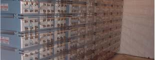

2 Rectifier Rectifiers convert ac into dc Some commercial rectifiers: (Used to charge batteries like those on the right)
3 Example of Assumed State Analysis V ac R L Consider the V ac > 0 case We make an intelligent t guess that t I is flowing out of the source node. If current is flowing, then the diode must be on We see that KVL (V ac =I R L ) is satisfied Thus, our assumed state is correct 3
4 Example of Assumed State Analysis 1V 11V 10V R L 11V We make an intelligent guess that I is flowing out of the 11V source If current is flowing, then the top diode must be on Current cannot flow backward through h the bottom diode, d so it must be off The bottom node of the load resistor is connected to the source reference, so there is a current path back to the 11V source KVL dictates that the load resistor has 11V across it The bottom diode is reverse biased, and thus confirmed to be off Thus our assumed state is correct 4
5 Assumed State Analysis V ac R L What are the states of the diodes on or off? Consider the V ac > 0 case We make an intelligent guess that I is flowing out of the source node. I cannot flow into diode #4, so diode #4 must be off. If current is flowing, then diode #1 must be on. I cannot flow into diode #3, so diode #3 must be off. I flows through R L. I comes to the junction of diodes # and #4. We have already determined that diode #4 is off. If current is flowing, then diode # must be on, and I continues to the V ac terminal. 5
6 Assumed State Analysis, cont. V ac > 0 1 R L A check of voltages confirms that diode #4 is indeed reverse biased as we have assumed A check of voltages confirms that diode #3 is indeed reverse biased as we have assumed We see that KVL (V ac = I R L ) is satisfied Thus, our assumed states are correct The same process can be repeated for V ac < 0, where it can be seen that diodes #3 and #4 are on, and diodes #1 and # are off 6
7 AC and DC Waveforms for a Resistive st e Load V ac >0 1 3 V dc 4 V ac < 0 V dc Vac Vdc ts Vol Vo olts Milliseconds -40 Milliseconds With a resistive load, the ac and dc current waveforms have the same waveshapes as Vac and Vdc shown above Note DC does not mean constant! 7
8 Half-wave rectifier 1 T V p Vdc vrdt sin( ) d T 0 0 V p t V p V dc t V ac R L 8
9 Full wave rectifier Waveforms v 1 T V p Vdc vrdt sin( ) d T 0 0 V p vr V p v V dc t t t R tifi d d Rectifier nd order Filter
10 Diode Bridge Rectifier (DBR) v Vp 10 V dc 170 V v Vdc 10 V dc 170Vdc t DC link t I ac 10V ac rms First order low pass filter 10 V dc 170Vdc 10
11 DC-Side Voltage and Current for Two Different Load Levels Vdc 00W Load 800W Load T 1 f Ripple voltage increases Idc Average current increases (current pulse gets taller and wider) I ac 1 I dc = I ac 3 10V ac rms 4 11
12 Approximate ppo Formula uafor DC Ripple ppevoltage otage With a first order low pass filter 1 1 CV peak CV min Pt Energy given up by capacitor as its voltage drops from Vpeak to Vmin Energy consumed by constant load power P during the same time interval V V V peak min V peak V min Pt C ( V peak Vmin )( V peak Vmin ) Pt C ( V peak V min ) C( V P t V peak min ) 1
13 ( V Approximate Formula for DC Ripple Voltage, cont. peak V min ) Pt C ( V Vmin ) peak min T/ For low ripple, V peak V min V V peak, and t T t T 1 f (V V Vmin ) V peak peak to peak ripple P fcv peak A second order low-pass filter realized by adding an inductor in the dclink allows to reduce the required capacitance for a given ripple goal. 13
14 AC Current Waveform 1 T = f The ac current waveform has significant harmonic content. High harmonic components circulating in the electric grid may create quality and technical problems (higher losses in cables and transformers). Harmonic content is measurements: total harmonic distortion (THD) and power factor 1 T ptdt () Average Power 0.. T pf Total Used (Apparent) Power VRMS IRMS V I I p. f. V I I 60 Hz, RMS 60 Hz, RMS 60 Hz, RMS 60 Hz, RMS RMS RMS 14


15 Vampire Loads =? Vampire loads have high leakage currents and low power factor. Your new lab safety tool: 15
16 Estimated Diode Conduction Losses Estimate the average value I avg of the i(t) v(t) ac current over the conduction interval T cond Estimate the average value Vavg of diode forward voltage drop over one conduction interval ltcond T cond Since the forward voltage on the diode is approximately constant during the conduction interval, the energy absorbed by the diode during the conduction interval is approximately V avg I avg T cond. Each diode has one conduction interval per 60Hz period, so the average power absorbed by all four diodes is then 4Vavg I avgtcond P 40V I T Watts. avg T 60 Hz avg avg cond 16

17 Forward Voltage on One Diode Zero Conducting Forward voltage on one diode Zero Zoom-In Forward voltage on one diode 17
18 AC CCurrent Waveform eo One pulse like this passes through each diode, once per cycle of 60Hz The shape is nearly triangular, so the average value is approximately one-half the peak 18
Experiment #2 Half Wave Rectifier
 PURPOSE: ELECTRONICS 224 ETR620S Experiment #2 Half Wave Rectifier This laboratory session acquaints you with the operation of a diode power supply. You will study the operation of half-wave and the effect
2.0 AC CIRCUITS 2.1 AC VOLTAGE AND CURRENT CALCULATIONS. ECE 4501 Power Systems Laboratory Manual Rev OBJECTIVE
 2.0 AC CIRCUITS 2.1 AC VOLTAGE AND CURRENT CALCULATIONS 2.1.1 OBJECTIVE To study sinusoidal voltages and currents in order to understand frequency, period, effective value, instantaneous power and average
CHAPTER 5 MODIFIED SINUSOIDAL PULSE WIDTH MODULATION (SPWM) TECHNIQUE BASED CONTROLLER
 TECHNIQUE BASED CONTROLLER") 74 CHAPTER 5 MODIFIED SINUSOIDAL PULSE WIDTH MODULATION (SPWM) TECHNIQUE BASED CONTROLLER 5.1 INTRODUCTION Pulse Width Modulation method is a fixed dc input voltage is given to the inverters and a controlled
74 CHAPTER 5 MODIFIED SINUSOIDAL PULSE WIDTH MODULATION (SPWM) TECHNIQUE BASED CONTROLLER 5.1 INTRODUCTION Pulse Width Modulation method is a fixed dc input voltage is given to the inverters and a controlled
Power Electronics Laboratory-2 Uncontrolled Rectifiers
 Roll. No: Checked By: Date: Grade: Power Electronics Laboratory-2 and Uncontrolled Rectifiers Objectives: 1. To analyze the working and performance of a and half wave uncontrolled rectifier. 2. To analyze
Sheet 2 Diodes. ECE335: Electronic Engineering Fall Ain Shams University Faculty of Engineering. Problem (1) Draw the
 Draw the") Ain Shams University Faculty of Engineering ECE335: Electronic Engineering Fall 2014 Sheet 2 Diodes Problem (1) Draw the i) Charge density distribution, ii) Electric field distribution iii) Potential distribution,
Ain Shams University Faculty of Engineering ECE335: Electronic Engineering Fall 2014 Sheet 2 Diodes Problem (1) Draw the i) Charge density distribution, ii) Electric field distribution iii) Potential distribution,
CHAPTER 4 FULL WAVE RECTIFIER. AC DC Conversion
 CHAPTER 4 FULL WAVE RECTIFIER AC DC Conversion SINGLE PHASE FULL-WAVE RECTIFIER The objective of a full wave rectifier is to produce a voltage or current which is purely dc or has some specified dc component.
EXPERIMENT 5 : THE DIODE
 EXPERIMENT 5 : THE DIODE Component List Resistors, one of each o 1 10 10W o 1 1k o 1 10k 4 1N4004 (I max = 1A, PIV = 400V) Diodes Center tap transformer (35.6V pp, 12.6 V RMS ) 100 F Electrolytic Capacitor
Equivalent dc load resistance. Important never connect a DBR directly to 120 V ac or directly to a variac. Idc + 28 R L. I ac.
 Overview Electronic loads, such as desktop computers and televisions, operate on dc rather than ac power. However, utility power is largely distributed in the U.S. through a 60 Hz ac system. Electronic
After performing this experiment, you should be able to:
 Objectives: After performing this experiment, you should be able to: Demonstrate the strengths and weaknesses of the two basic rectifier circuits. Draw the output waveforms for the two basic rectifier
EXPERIMENT 5 : THE DIODE
 EXPERIMENT 5 : THE DIODE Equipment List Dual Channel Oscilloscope R, 330, 1k, 10k resistors P, Tri-Power Supply V, 2x Multimeters D, 4x 1N4004: I max = 1A, PIV = 400V Silicon Diode P 2 35.6V pp (12.6 V
Basic Electronic Devices and Circuits EE 111 Electrical Engineering Majmaah University 2 nd Semester 1432/1433 H. Chapter 2. Diodes and Applications
 Basic Electronic Devices and Circuits EE 111 Electrical Engineering Majmaah University 2 nd Semester 1432/1433 H Chapter 2 Diodes and Applications 1 Diodes A diode is a semiconductor device with a single
Sirindhorn International Institute of Technology Thammasat University at Rangsit
 Sirindhorn International Institute of Technology Thammasat University at Rangsit School of Information, Computer and Communication Technology COURSE : ECS 204 Basic Electrical Engineering Lab INSTRUCTOR
Electronic I Lecture 3 Diode Rectifiers. By Asst. Prof Dr. Jassim K. Hmood
 Electronic I Lecture 3 Diode Rectifiers By Asst. Prof Dr. Jassim K. Hmood Diode Approximations 1- The Ideal Model When forward biased, act as a closed (on) switch When reverse biased, act as open (off)
Circuit operation Let s look at the operation of this single diode rectifier when connected across an alternating voltage source v s.
 Diode Rectifier Circuits One of the important applications of a semiconductor diode is in rectification of AC signals to DC. Diodes are very commonly used for obtaining DC voltage supplies from the readily
Experiment E7 DC Power Supply Worst-Case Design for Half-Wave Rectifier Circuit James J. Whalen Fall 2000
 Experiment E7 DC Power Supply Worst-Case Design for Half-Wave Rectifier Circuit James J. Whalen Fall 2000 Experiment No. 7 DC Power Supply (Half-Wave Rectifier Circuit) provides an opportunity to perform
ELG4139: DC to AC Converters
 ELG4139: DC to AC Converters Converts DC to AC power by switching the DC input voltage (or current) in a pre-determined sequence so as to generate AC voltage (or current) output. I DC I ac + + V DC V ac
APPLICATIONS DATA SHEET. Product: Single Phase AC/DC Power Meter QI-POWER-485
 APPLICATIONS DATA SHEET Product: Single Phase AC/DC Power Meter QI-POWER-485 Renewable energy: 1. PV String Monitoring: the QI-POWER-485 measures DC current up to 50 A and DC voltage up to 1000 V, with
Power Electronics Day 5 Dc-dc Converters; Classical Rectifiers
 Power Electronics Day 5 Dc-dc Converters; Classical Rectifiers P. T. Krein Department of Electrical and Computer Engineering University of Illinois at Urbana-Champaign 2011 Philip T. Krein. All rights
Power Quality Notes 2-1 (MT)
") Power Quality Notes 2-1 (MT) Marc Thompson, Ph.D. Senior Managing Engineer Exponent 21 Strathmore Road Natick, MA 01760 Alex Kusko, Sc.D, P.E. Vice President Exponent 21 Strathmore Road Natick, MA 01760
Power Quality Notes 2-1 (MT) Marc Thompson, Ph.D. Senior Managing Engineer Exponent 21 Strathmore Road Natick, MA 01760 Alex Kusko, Sc.D, P.E. Vice President Exponent 21 Strathmore Road Natick, MA 01760
Applications of Diode
 Applications of Diode Diode Approximation: (Large signal operations): 1. Ideal Diode: When diode is forward biased, resistance offered is zero, When it is reverse biased resistance offered is infinity.
University of Pittsburgh
 University of Pittsburgh Experiment #5 Lab Report Diode Applications and PSPICE Introduction Submission Date: 10/10/2017 Instructors: Dr. Minhee Yun John Erickson Yanhao Du Submitted By: Nick Haver & Alex
Sirindhorn International Institute of Technology Thammasat University at Rangsit
 Sirindhorn International Institute of Technology Thammasat University at Rangsit School of Information, Computer and Communication Technology COURSE : ECS 204 Basic Electrical Engineering Lab INSTRUCTOR
Assuming continuous conduction, the circuit has two topologies switch closed, and switch open. These are shown in Figures 2a and 2b. L i C.
 EE46, Power Electronics, DC-DC Buck Converter Version Sept. 9, 011 Overview DC-DC converters provide efficient conversion of DC voltage from one level to another. Specifically, the term buck converter
ECE321 Electronics I
 ECE321 Electronics Lecture 2: Basic Circuits with Diodes Payman Zarkesh-Ha Office: ECE Bldg. 230B Office hours: Tuesday 2:00-3:00PM or by appointment E-mail: pzarkesh.unm.edu Slide: 1 Review of Last Lecture
2) The larger the ripple voltage, the better the filter. 2) 3) Clamping circuits use capacitors and diodes to add a dc level to a waveform.
 The larger the ripple voltage, the better the filter. 2) 3) Clamping circuits use capacitors and diodes to add a dc level to a waveform.") TRUE/FALSE. Write 'T' if the statement is true and 'F' if the statement is false. 1) A diode conducts current when forward-biased and blocks current when reverse-biased. 1) 2) The larger the ripple voltage,
TRUE/FALSE. Write 'T' if the statement is true and 'F' if the statement is false. 1) A diode conducts current when forward-biased and blocks current when reverse-biased. 1) 2) The larger the ripple voltage,
Power Supplies. Linear Regulated Supplies Switched Regulated Supplies Batteries
 Power Supplies Linear Regulated Supplies Switched Regulated Supplies Batteries Im Alternating Current The Power -Im π/2 π 2π π t Im Idc Direct Current Supply π/2 π 2 π πt -Im ٢ http://bkaragoz.kau.edu.sa
SKEU 3741 BASIC ELECTRONICS LAB
 Faculty: Subject Subject Code : SKEU 3741 FACULTY OF ELECTRICAL ENGINEERING : 2 ND YEAR ELECTRONIC DESIGN LABORATORY Review Release Date Last Amendment Procedure Number : 1 : 2013 : 2013 : PK-UTM-FKE-(0)-10
Lab 2: Linear and Nonlinear Circuit Elements and Networks
 OPTI 380B Intermediate Optics Laboratory Lab 2: Linear and Nonlinear Circuit Elements and Networks Objectives: Lean how to use: Function of an oscilloscope probe. Characterization of capacitors and inductors
Basic DC Power Supply
 Basic DC Power Supply Equipment: 1. Analog Oscilloscope 2. Digital multimeter 3. Experimental board and connectors. Objectives: 1. To understand the basic DC power supply both half wave and full wave rectifier.
ECE 3410 Homework 4 (C) (B) (A) (F) (E) (D) (H) (I) Solution. Utah State University 1 D1 D2. D1 v OUT. v IN D1 D2 D1 (G)
 (B) (A) (F) (E) (D) (H) (I) Solution. Utah State University 1 D1 D2. D1 v OUT. v IN D1 D2 D1 (G)") ECE 341 Homework 4 Problem 1. In each of the ideal-diode circuits shown below, is a 1 khz sinusoid with zero-to-peak amplitude 1 V. For each circuit, sketch the output waveform and state the values of
ECE 341 Homework 4 Problem 1. In each of the ideal-diode circuits shown below, is a 1 khz sinusoid with zero-to-peak amplitude 1 V. For each circuit, sketch the output waveform and state the values of
LECTURE.3 : AC-DC CONVERSION
 LECTURE.3 : AC-DC CONVERSION (RECTIFICATIONS) 3.1Basic Rectifier Circuits Several types of rectifier circuits are available: single-phase and three-phase half-wave and full-wave, controlled and uncontrolled,
EXPERIMENT 3 Half-Wave and Full-Wave Rectification
 Name & Surname: ID: Date: EXPERIMENT 3 Half-Wave and Full-Wave Rectification Objective To calculate, compare, draw, and measure the DC output voltages of half-wave and full-wave rectifier circuits. Tools
Increasing the Performance of PFC and LED Driver Applications
 Increasing the Performance of PFC and LED Driver Applications Renesas Electronics America Inc. Renesas Technology & Solution Portfolio 2 Discrete and Integrated Power Products 30V-1500V in Application
Electronics for Analog Signal Processing - I Prof. K. Radhakrishna Rao Department of Electrical Engineering Indian Institute of Technology - Madras
 Electronics for Analog Signal Processing - I Prof. K. Radhakrishna Rao Department of Electrical Engineering Indian Institute of Technology - Madras Lecture - 6 Full Wave Rectifier and Peak Detector In
EXPERIMENT 5 : THE DIODE
 EXPERIMENT 5 : THE DIODE Component List Resistors, one of each o 1 10 10W o 1 1k o 1 10k 4 1N4004 (Imax = 1A, PIV = 400V) Diodes Center tap transformer (35.6Vpp, 12.6 VRMS) 100 F Electrolytic Capacitor
Principle Of Step-up Chopper
 Principle Of Step-up Chopper L + D + V Chopper C L O A D V O 1 Step-up chopper is used to obtain a load voltage higher than the input voltage V. The values of L and C are chosen depending upon the requirement
Diodes This week, we look at switching diodes, LEDs, and diode rectification. Be sure to bring a flash drive for recording oscilloscope traces.
 Diodes This week, we look at switching diodes, LEDs, and diode rectification. Be sure to bring a flash drive for recording oscilloscope traces. 1. Basic diode characteristics Build the circuit shown in
Differential-Mode Emissions
 Differential-Mode Emissions In Fig. 13-5, the primary purpose of the capacitor C F, however, is to filter the full-wave rectified ac line voltage. The filter capacitor is therefore a large-value, high-voltage
EE351 Laboratory Exercise 1 Diode Circuits
 revised July 19, 2009 The purpose of this laboratory exercise is to gain experience and understanding working with diodes. Focus on taking good data so that the plots and calculations you will do later
POWER ELECTRONICS LAB MANUAL
 JIS College of Engineering (An Autonomous Institution) Department of Electrical Engineering POWER ELECTRONICS LAB MANUAL Exp-1. Study of characteristics of an SCR AIM: To obtain the V-I characteristics
Electronic Devices. Floyd. Chapter 2. Ninth Edition. Electronic Devices, 9th edition Thomas L. Floyd
 Electronic Devices Ninth Edition Floyd Chapter 2 Agenda Diode Circuits and Applications Half-wave Rectifier Full-wave Rectifier Power Supply Filter Power Supply Regulator Diode Limiting Circuits Diode
14. DC to AC Converters
 14. DC to AC Converters Single-phase inverters: 14.1 Single-phase half-bridge inverter This type of inverter is very simple in construction. It does not need output transformer like parallel inverter.
Power Factor Pre-regulator Using Constant Tolerance Band Control Scheme
 Power Factor Pre-regulator Using Constant Tolerance Band Control Scheme Akanksha Mishra, Anamika Upadhyay Akanksha Mishra is a lecturer ABIT, Cuttack, India (Email: misakanksha@gmail.com) Anamika Upadhyay
Federal Urdu University of Arts, Science & Technology Islamabad Pakistan SECOND SEMESTER ELECTRONICS - I
 SECOND SEMESTER ELECTRONICS - I BASIC ELECTRICAL & ELECTRONICS LAB DEPARTMENT OF ELECTRICAL ENGINEERING Prepared By: Checked By: Approved By: Engr. Yousaf Hameed Engr. M.Nasim Khan Dr.Noman Jafri Lecturer
RECTIFIERS AND POWER SUPPLIES
 UNIT V RECTIFIERS AND POWER SUPPLIES Half-wave, full-wave and bridge rectifiers with resistive load. Analysis for Vdc and ripple voltage with C,CL, L-C and C-L-C filters. Voltage multipliers Zenerdiode
EXPERIMENT 5 : DIODES AND RECTIFICATION
 EXPERIMENT 5 : DIODES AND RECTIFICATION Component List Resistors, one of each o 2 1010W o 1 1k o 1 10k 4 1N4004 (Imax = 1A, PIV = 400V) Diodes Center tap transformer (35.6Vpp, 12.6 VRMS) 100 F Electrolytic
Başkent University Department of Electrical and Electronics Engineering EEM 214 Electronics I Experiment 2. Diode Rectifier Circuits
 Başkent University Department of Electrical and Electronics Engineering EEM 214 Electronics I Experiment 2 Diode Rectifier Circuits Aim: The purpose of this experiment is to become familiar with the use
Chapter 1: Introduction
 1.1. Introduction to power processing 1.2. Some applications of power electronics 1.3. Elements of power electronics Summary of the course 2 1.1 Introduction to Power Processing Power input Switching converter
EXPERIMENT 7: DIODE CHARACTERISTICS AND CIRCUITS 10/24/10
 DIODE CHARACTERISTICS AND CIRCUITS EXPERIMENT 7: DIODE CHARACTERISTICS AND CIRCUITS 10/24/10 In this experiment we will measure the I vs V characteristics of Si, Ge, and Zener p-n junction diodes, and
Lab 1 Power electronics
 5--24 (5) Lab Power electronics Contents Introduction... Initial setup... 2 Starting the software... 2 Notes on the schematics... 2 Simulating the design... 2 Existing simulation variables... 3 Extra measurement
ECE 2274 Diode Basics and a Rectifier Completed Prior to Coming to Lab
 ECE 2274 Diode Basics and a Rectifier Completed Prior to Coming to Lab Perlab: Part I I-V Characteristic Curve for the 1. Construct the circuit shown in figure 1. Using a DC Sweep, simulate in LTspice
DEPARTMENT OF ELECTRICAL ENGINEERING LAB WORK EE301 ELECTRONIC CIRCUITS
 DEPARTMENT OF ELECTRICAL ENGINEERING LAB WORK EE301 ELECTRONIC CIRCUITS EXPERIMENT : 1 TITLE : Half-Wave Rectifier & Filter OUTCOME : Upon completion of this unit, the student should be able to: i. Construct
81357 Series PFC Boost Module Application Information
 81357 Series PFC Boost Module Application Information OVERVIEW Implementing power factor correction (PFC) into switch mode power supplies maximizes the power handling capability of the power supply and
Chapter 2. Diodes & Applications
 Chapter 2 Diodes & Applications The Diode A diode is made from a small piece of semiconductor material, usually silicon, in which half is doped as a p region and half is doped as an n region with a pn
3. Diode, Rectifiers, and Power Supplies
 3. Diode, Rectifiers, and Power Supplies Semiconductor diodes are active devices which are extremely important for various electrical and electronic circuits. Diodes are active non-linear circuit elements
TSTE19 Power Electronics. Lecture3 Tomas Jonsson ICS/ISY
 TSTE19 Power Electronics Lecture3 Tomas Jonsson ICS/ISY 2015-11-09 2 Outline Rectifiers Current commutation Rectifiers, cont. Three phase 2015-11-09 3 Effect of L s on current commutation Current commutation
ECE 2006 University of Minnesota Duluth Lab 11. AC Circuits
 1. Objective AC Circuits In this lab, the student will study sinusoidal voltages and currents in order to understand frequency, period, effective value, instantaneous power and average power. Also, the
Low Distortion Design 4
 Low Distortion Design 4 TIPL 1324 TI Precision Labs Op Amps Presented by Collin Wells Prepared by John Caldwell Prerequisites: Noise 1 3 (TIPL1311 TIPL1313) Distortion from Power Supplies Power supplies
Increasing the Performance of PFC and LED Driver Applications
 Increasing the Performance of PFC and LED Driver Applications Tad Keeley Sr. Marketing Director Class ID: AC04B Renesas Electronics America Inc. Tad Keeley : Sr. Marketing Director Renesas Electronics
Power Electronics Single Phase Uncontrolled Half Wave Rectifiers. Dr. Firas Obeidat
 Power Electronics Single Phase Uncontrolled Half Wave Rectifiers Dr. Firas Obeidat 1 Table of contents 1 Resistive Load 2 R-L Load 3 R-L Load with Freewheeling Diode 4 Half Wave Rectifier with a Capacitor
ECE 2274 Pre-Lab for Experiment # 4 Diode Basics and a Rectifier Completed Prior to Coming to Lab
 Part I I-V Characteristic Curve ECE 2274 Pre-Lab for Experiment # 4 Diode Basics and a Rectifier Completed Prior to Coming to Lab 1. Construct the circuit shown in figure 4-1. Using a DC Sweep, simulate
Chapter 3 - Waveforms, Power and Measurement
 Chapter 3 - Waveforms, Power and Measurement Recommended problems to study: Problem Page Concentrates 3: Low-pass filter/fourier series < : Two wattmeter 3-f power measurement Timed 3: DC ammeter 4< 5:
+ 24V 3.3K - 1.5M. figure 01
 ELECTRICITY ASSESSMENT 35 questions Revised: 08 Jul 2013 1. Which of the wire sizes listed below results in the least voltage drop in a circuit carrying 10 amps: a. 16 AWG b. 14 AWG c. 18 AWG d. 250 kcmil
BEST BMET CBET STUDY GUIDE MODULE ONE
 BEST BMET CBET STUDY GUIDE MODULE ONE 1 OCTOBER, 2008 1. The phase relation for pure capacitance is a. current leads voltage by 90 degrees b. current leads voltage by 180 degrees c. current lags voltage
PR Rectifier Module
 PR500-280 Rectifier Module Block Diagram External Resistor R2 R1 AC (L) Inrush Current Limit Circuit +V External Electrolytic Capacitor + AC (N) -V Power Supply Input Sensing Sequency Timing Diagram More
EE292: Fundamentals of ECE
 EE292: Fundamentals of ECE Fall 2012 TTh 10:00-11:15 SEB 1242 Lecture 12 121004 http://www.ee.unlv.edu/~b1morris/ee292/ 2 Outline Review More Diodes Lab Kits 3 Diode Voltage/Current Characteristics Forward
ECE1750, Spring dc-ac power conversion
 ECE1750, Spring 2018 dc-ac power conversion (inverters) 1 H-Bridge Inverter Basics Creating AC from DC Single-phase H-bridge bid (voltage Switching rules source) inverter topology: Either A+ or A is closed,
AC VOLTAGE CONTROLLER (RMS VOLTAGE CONTROLLERS)
") AC VOLTAGE CONTROLLER (RMS VOLTAGE CONTROLLERS) INTRODUCTION AC voltage controllers (AC line voltage controllers): are employed to vary the RMS value of the alternating voltage applied to a load circuit
AC VOLTAGE CONTROLLER (RMS VOLTAGE CONTROLLERS) INTRODUCTION AC voltage controllers (AC line voltage controllers): are employed to vary the RMS value of the alternating voltage applied to a load circuit
1) Consider the circuit shown in figure below. Compute the output waveform for an input of 5kHz
 Consider the circuit shown in figure below. Compute the output waveform for an input of 5kHz") ) Consider the circuit shown in figure below. Compute the output waveform for an input of 5kHz Solution: a) Input is of constant amplitude of 2 V from 0 to 0. ms and 2 V from 0. ms to 0.2 ms. The output
) Consider the circuit shown in figure below. Compute the output waveform for an input of 5kHz Solution: a) Input is of constant amplitude of 2 V from 0 to 0. ms and 2 V from 0. ms to 0.2 ms. The output
CHAPTER 5 POWER QUALITY IMPROVEMENT BY USING POWER ACTIVE FILTERS
 86 CHAPTER 5 POWER QUALITY IMPROVEMENT BY USING POWER ACTIVE FILTERS 5.1 POWER QUALITY IMPROVEMENT This chapter deals with the harmonic elimination in Power System by adopting various methods. Due to the
(A) im (B) im (C)0.5 im (D) im.
 im (B) im (C)0.5 im (D) im.") Dr. Mahalingam College of Engineering and Technology, Pollachi. (An Autonomous Institution affiliated to Anna University) Regulation 2014 Fourth Semester Electrical and Electronics Engineering 141EE0404
Dr. Mahalingam College of Engineering and Technology, Pollachi. (An Autonomous Institution affiliated to Anna University) Regulation 2014 Fourth Semester Electrical and Electronics Engineering 141EE0404
Operation and Maintenance Manual
 WeiKedz 0-30V 2mA-3A Adjustable DC Regulated Power Supply DIY Kit Operation and Maintenance Manual The WeiKedz Adjustable DC Regulated Power Supply provides continuously variable output voltage between
Objective Type Questions 1. Why pure semiconductors are insulators at 0 o K? 2. What is effect of temperature on barrier voltage? 3.
 Objective Type Questions 1. Why pure semiconductors are insulators at 0 o K? 2. What is effect of temperature on barrier voltage? 3. What is difference between electron and hole? 4. Why electrons have
Lecture (04) PN Diode applications II
 PN Diode applications II") Lecture (04) PN Diode applications II By: Dr. Ahmed ElShafee ١ Agenda Full wave rectifier, cont.,.. Filters Voltage Regulators ٢ RMS The RMS value of a set of values (or a continuous time waveform) is
Lecture (04) PN Diode applications II By: Dr. Ahmed ElShafee ١ Agenda Full wave rectifier, cont.,.. Filters Voltage Regulators ٢ RMS The RMS value of a set of values (or a continuous time waveform) is
Diodes Notes ECE 2210
 Diodes Notes ECE 10 Diodes are basically electrical check valves. They allow current to flow freely in one direction, but not the other. Check valves require a small forward pressure to open the valve.
Sample Exam Solution
 Session 44; 1/6 Sample Exam Solution Problem 1: You are given a single phase diode rectifier, as shown below. Do the following: L d I s v (t) s L s C d V d Load : 310V Xs : 0.4ohm at 400 Hz Vspk : 360V
UNIVERSITY OF NORTH CAROLINA AT CHARLOTTE. Department of Electrical and Computer Engineering
 UNIVERSITY OF NORTH CAROLINA AT CHARLOTTE Department of Electrical and Computer Engineering Experiment No. 2 - Semiconductor Diodes Overview: In this lab session students will investigate I-V characteristics
UNIVERSITY OF NORTH CAROLINA AT CHARLOTTE Department of Electrical and Computer Engineering
 UNIVERSITY OF NORTH CAROLINA AT CHARLOTTE Department of Electrical and Computer Engineering EXPERIMENT 8 AMPLITUDE MODULATION AND DEMODULATION OBJECTIVES The focus of this lab is to familiarize the student
Lab Report 2 Half, Full and clipping Circuits of Diodes
 Abu Dhabi University Electronic Devices and Circuits Lab Report 2 Half, Full and clipping Circuits of Diodes Author: Muhammad Obaidullah 1030313 Hezam Salem 1014191 Salem Mohammad 1012824 Supervisor: Dr.
ENGR-4300 Spring 2009 Test 4. Name SOLUTION. Section 1(MR 8:00) 2(TF 2:00) 3(MR 6:00) (circle one) Question I (20 points) Question II (20 points)
 2(TF 2:00) 3(MR 6:00) (circle one) Question I (20 points) Question II (20 points)") ENGR-43 Spring 29 Test 4 Name SOLUTION Section 1(MR 8:) 2(TF 2:) 3(MR 6:) (circle one) Question I (2 points) Question II (2 points) Question III (15 points) Question IV (25 points) Question V (2 points)
ENGR-43 Spring 29 Test 4 Name SOLUTION Section 1(MR 8:) 2(TF 2:) 3(MR 6:) (circle one) Question I (2 points) Question II (2 points) Question III (15 points) Question IV (25 points) Question V (2 points)
High Power Factor Correction Circuit using Valley Charge-Pumping for Low Cost Electronic Ballasts
 High Power Factor Correction Circuit using Valley Charge-Pumping for Low Cost Electronic Ballasts Gyun Chae, Yong-Sik Youn and Gyu-Hyeong Cho Department of Electrical Engineering Korea Advanced Institute
AN5058 Application note
 AN5058 Application note Low-cost STM8 / STM32 power supply from mains Introduction In most non-battery applications, power is supplied to the microcontroller (MCU) using a step-down transformer, the output
Power Electronics in PV Systems
 Introduction to Power Electronics in PV Systems EEN 2060 References: EEN4797/5797 Intro to Power Electronics ece.colorado.edu/~ecen5797 Textbook: R.W.Erickson, D.Maksimovic, Fundamentals of Power Electronics,
ELEC387 Power electronics
 ELEC387 Power electronics Jonathan Goldwasser 1 Power electronics systems pp.3 15 Main task: process and control flow of electric energy by supplying voltage and current in a form that is optimally suited
Electro - Principles I
 Page 12-1 The Basic Power Supply The Power Supply The power supply is used to convert the AC energy provided by the wall outlet to dc energy. In most electronic equipment, the power cord supplies the ac
Power Management for Computer Systems. Prof. C Wang
 ECE 5990 Power Management for Computer Systems Prof. C Wang Fall 2010 Course Outline Fundamental of Power Electronics cs for Computer Systems, Handheld Devices, Laptops, etc More emphasis in DC DC converter
Modelling And Analysis of DVR With SEPIC Converter And Supercapacitor
 Modelling And Analysis of DVR With SEPIC Converter And Supercapacitor 1 Mugitha E, 2 Raji Krishna 1PG student, Dept. of Electrical and Electronics, Govt. Engineering College, Barton Hill, Trivandrum, India
Converters with Power Factor Correction
 32 ACTA ELECTROTEHNICA Converters with Power Factor Correction Daniel ALBU, Nicolae DRĂGHICIU, Gabriela TONŢ and Dan George TONŢ Abstract Traditional diode rectifiers that are commonly used in electrical
RC circuit. Recall the series RC circuit.
 RC circuit Recall the series RC circuit. If C is discharged and then a constant voltage V is suddenly applied, the charge on, and voltage across, C is initially zero. The charge ultimately reaches the
Design and Simulation of New Efficient Bridgeless AC- DC CUK Rectifier for PFC Application
 Design and Simulation of New Efficient Bridgeless AC- DC CUK Rectifier for PFC Application Thomas Mathew.T PG Student, St. Joseph s College of Engineering, C.Naresh, M.E.(P.hd) Associate Professor, St.
Lab 4: Junction Diodes
 Page 1 of 5 Laboratory Goals Analyzing, simulating and building a diode-based circuit. Taking measurements and applying transformations to obtain the diode I-V curve. Use the curve tracer to verify the
Chapter 1 Introduction to Electronics
 Chapter 1 Introduction to Electronics Section 1-1 Atomic Structure 1. An atom with an atomic number of 6 has 6 electrons and 6 protons.. The third shell of an atom can have n = (3) = 18 electrons. Section
Electronic Circuits I Laboratory 03 Rectifiers
 Electronic Circuits I Laboratory 03 Rectifiers # Student ID Student Name Grade (10) 1 Instructor signature 2 3 4 5 Delivery Date -1 / 18 - Objectives In this experiment, you will get to know a group of
Lecture 6 ECEN 4517/5517
 Lecture 6 ECEN 4517/5517 Experiment 4: inverter system Battery 12 VDC HVDC: 120-200 VDC DC-DC converter Isolated flyback DC-AC inverter H-bridge v ac AC load 120 Vrms 60 Hz d d Feedback controller V ref
Active Rectifier in Microgrid
 03.09.2012 Active Rectifier in Microgrid - Developing a simulation model in SimPower - Dimensioning the filter - Current controller comparison - Calculating average losses in the diodes and transistors
CHAPTER 3. SINGLE-STAGE PFC TOPOLOGY GENERALIZATION AND VARIATIONS
 CHAPTER 3. SINGLE-STAGE PFC TOPOLOG GENERALIATION AND VARIATIONS 3.1. INTRODUCTION The original DCM S 2 PFC topology offers a simple integration of the DCM boost rectifier and the PWM DC/DC converter.
Fundamental of Electrical Engineering Lab Manual
 Fundamental of Electrical Engineering Lab Manual EngE-111/318 Dr.Hidayath Mirza & Dr.Rais Ahmad Sheikh 1/9/19 EngE111 Testing Battery (DC) Testing AC Testing Wire 1 P a g e Resistor measurement Testing
Clippers limiter circuits Vi > V Vi < V
 Semiconductor Diode Clipper and Clamper Circuits Clippers Clipper circuits, also called limiter circuits, are used to eliminate portion of a signal that are above or below a specified level clip value.
AC Theory and Electronics
 AC Theory and Electronics An Alternating Current (AC) or Voltage is one whose amplitude is not constant, but varies with time about some mean position (value). Some examples of AC variation are shown below:
 FINALTERM EXAMINATION Fall 2009 PHY301- Circuit Theory (Session - 2) Time: 120 min Marks: 70 Question No: 1 ( Marks: 1 ) - Please choose one Charge of 2c and 5c will attract each other repel each other