RC circuit. Recall the series RC circuit.
|
|
|
- Arline McCarthy
- 6 years ago
- Views:
Transcription
1 RC circuit Recall the series RC circuit. If C is discharged and then a constant voltage V is suddenly applied, the charge on, and voltage across, C is initially zero. The charge ultimately reaches the value Q=CV and current ceases. The characteristic time is RC.

2 Capacitors in an AC Circuit Consider an AC voltage applied to a capacitor. Neglect any resistance in the wires. The charge follows the drive voltage. The current is the time derivative of the charge and leads the drive voltage by 90 degrees. The capacitive reactance XC is large at low frequency and small at high frequency.
3 Capacitors in an AC Circuit A capacitor is connected between the terminals of a variablefrequency fixed-amplitude AC voltage source. Is there more current through the capacitor at low frequency or at high frequency?
4 Capacitors in an AC Circuit A capacitor is connected between the terminals of a variablefrequency fixed-amplitude AC voltage source. Is there more current through the capacitor at low frequency or at high frequency? The capacitive reactance XC is large at low frequency and small at high frequency. The current is small at low frequency and large at high frequency.

5 More About Capacitors in an AC Circuit The current is largest when the capacitor charge and voltage are small. The current reaches its maximum value one quarter of a cycle sooner than the voltage reaches its maximum value. The current leads the voltage by 90 o.

6 Phasor Diagram for Capacitor The phasor diagram shows that for a sinusoidally applied voltage, the current always leads the voltage across a capacitor by 90 o.
7 The RLC Series Circuit The resistor, inductor, and capacitor can be combined in a circuit. The current and the voltage in the circuit vary sinusoidally with time. Current conservation implies the current in each element is identical in amplitude and phase.
 When time varies, the sin function may be 1 while the cos function may vanish and vice versa.")
8 The RLC Series Circuit, cont. Equate the instantaneous drive voltage to the sum of voltage drops and use trig identities to expand. (I is the current amplitude, phi its phase.) When time varies, the sin function may be 1 while the cos function may vanish and vice versa. The sum of coefficients of sin(omega t) and the sum of coefficients of cos(omega t) must separately vanish.

9 The RLC Series Circuit, cont. Solve for the unknown amplitude and phase of the current.


10 Alternate solution using phasor diagram The individual phasor diagrams can be combined. Here a single phasor Imax is used to represent the current in each element. From the phasor diagram, ΔV max can be calculated in terms of VR= IR, V L = I X L, and V C = IX C.

11 Impedance and resonance frequency The current in an RLC circuit can be expressed in terms of the impedance of the RLC combination called Z. Impedance has units of ohms. At high frequency, φ is positive X L > X C and the current lags the applied voltage. The circuit is more inductive than capacitive. At low frequency, φ is negative, X L < X C, and the current leads the applied voltage.the circuit is more capacitive than inductive. If φ is zero, X L = X C. The impedance has a minimum and the current a maximum. The circuit is purely resistive. This occurs at the resonance frequency (LC) -1/2.
12 Power in an AC Circuit The average power delivered by the AC source is converted to internal energy in the resistor. P avg = ½ I max ΔV max cos φ = I rms ΔV rms cos φ cos φ is called the power factor of the circuit We can also find the average power in terms of R. P avg = I 2 rmsr When the load is purely resistive, φ = 0 and cos φ = 1 P avg = I rms ΔV rms
13 Resonance, cont. Resonance occurs at the same frequency regardless of the value of R. As R decreases, the curve becomes narrower and taller. Theoretically, if R = 0 the current would be infinite at resonance. Real circuits always have some resistance. The sharpness of the resonance curve is usually described by a dimensionless parameter known as the quality factor, Q. Q = " o / #" = (" o L) / R #" is the width of the curve, measured between the two values of " for which P avg has half its maximum value.

14 Transformers An AC transformer consists of two coils of wire wound around a core of iron. The side connected to the input AC voltage source is called the primary and has N 1 turns. The other side, called the secondary, is connected to a resistor and has N 2 turns. The core is used to increase the magnetic flux and to provide a medium for the flux to pass from one coil to the other. Assuming all the magnetic flux circulates through both coils, the voltages are related by the ratio of the number of turns. The power input into the primary equals the power output at the secondary. I 1 ΔV 1 = I 2 ΔV 2 The equivalent resistance of the load resistance when viewed from the primary is given by the square of the turns ratio.
 in the positive portion of the cycle. (half wave rectification).")
15 Rectifier Circuit A diode has low resistance to current flow in on direction and high resistance to current flow in the opposite direction. With no capacitor, the alternating current in the load resistor is reduced (ideally to zero) in the positive portion of the cycle. (half wave rectification). The capacitor buffers the voltage - we have a simple AC-to-DC converter (with ripple). The transformer reduces the 120 V AC to the 6 V or 9 V typically needed.

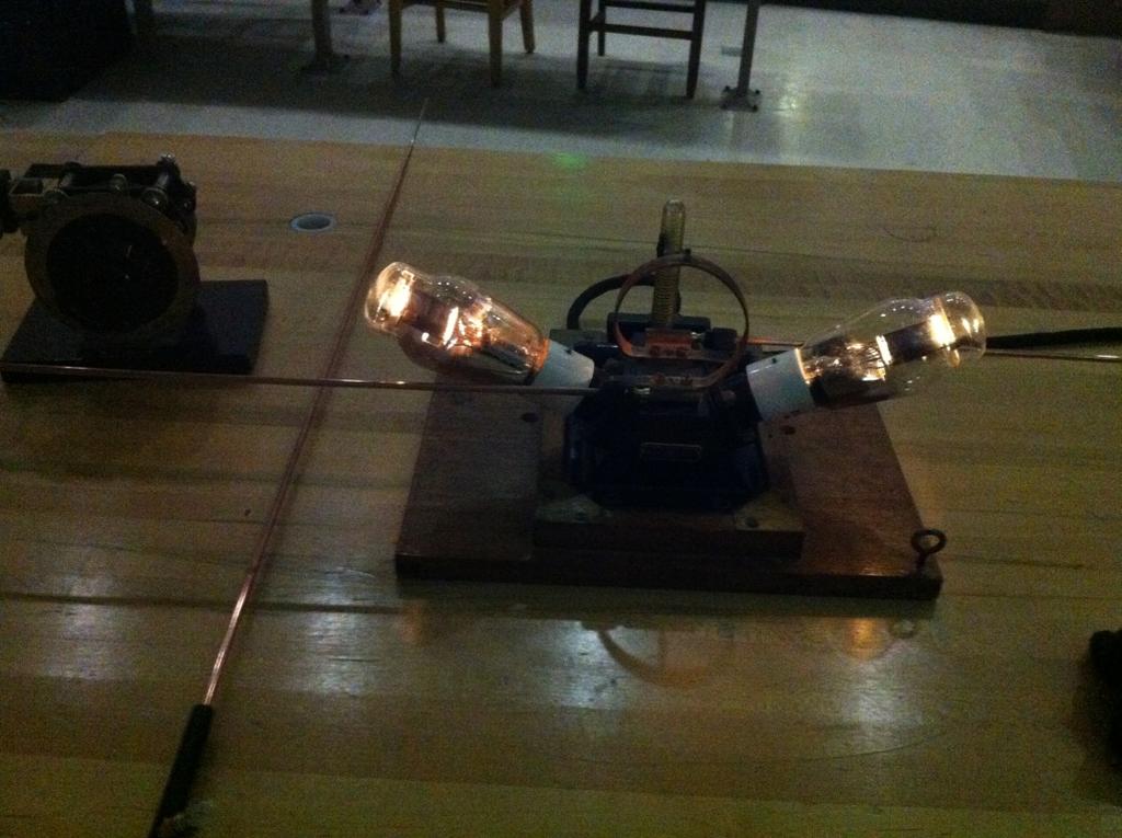
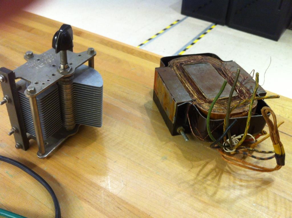
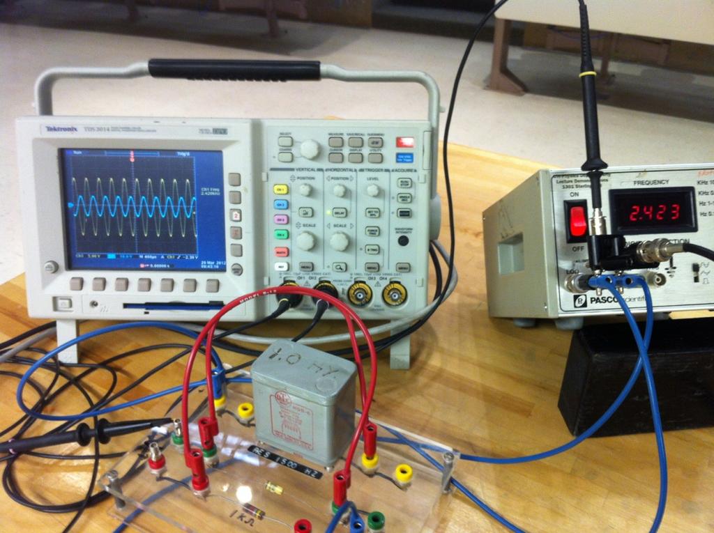
16 LRC circuit demonstrations
17 Low pass filter circuit A filter circuit is used to smooth out or eliminate a time-varying signal such as the ripple in the output of an AC-to-DC converter. At low frequencies, the reactance and voltage across the capacitor are high. As the frequency increases, the reactance and voltage decrease.

18 High-Pass Filter A high-pass filter is designed to preferentially pass signals of higher frequency and block lower frequency signals. At low frequencies, the capacitor has high reactance and much of the applied voltage appears across the capacitor. At high frequencies, the capacitive reactance is small and the voltage appears across the resistor.
Chapter 33. Alternating Current Circuits
 Chapter 33 Alternating Current Circuits Alternating Current Circuits Electrical appliances in the house use alternating current (AC) circuits. If an AC source applies an alternating voltage to a series
An induced emf is the negative of a changing magnetic field. Similarly, a self-induced emf would be found by
 This is a study guide for Exam 4. You are expected to understand and be able to answer mathematical questions on the following topics. Chapter 32 Self-Induction and Induction While a battery creates an
Lecture Outline Chapter 24. Physics, 4 th Edition James S. Walker. Copyright 2010 Pearson Education, Inc.
 Lecture Outline Chapter 24 Physics, 4 th Edition James S. Walker Chapter 24 Alternating-Current Circuits Units of Chapter 24 Alternating Voltages and Currents Capacitors in AC Circuits RC Circuits Inductors
Chapter 30 Inductance, Electromagnetic. Copyright 2009 Pearson Education, Inc.
 Chapter 30 Inductance, Electromagnetic Oscillations, and AC Circuits 30-7 AC Circuits with AC Source Resistors, capacitors, and inductors have different phase relationships between current and voltage
Chapter 33. Alternating Current Circuits
 Chapter 33 Alternating Current Circuits C HAP T E O UTLI N E 33 1 AC Sources 33 2 esistors in an AC Circuit 33 3 Inductors in an AC Circuit 33 4 Capacitors in an AC Circuit 33 5 The L Series Circuit 33
Physics for Scientists & Engineers 2 2 = 1 LC. Review ( ) Review (2) Review (3) e! Rt. cos "t + # ( ) q = q max. Spring Semester 2005 Lecture 30 U E
 Review (2) Review (3) e! Rt. cos t + # ( ) q = q max. Spring Semester 2005 Lecture 30 U E") Review hysics for Scientists & Engineers Spring Semester 005 Lecture 30! If we have a single loop RLC circuit, the charge in the circuit as a function of time is given by! Where q = q max e! Rt L cos "t
Review hysics for Scientists & Engineers Spring Semester 005 Lecture 30! If we have a single loop RLC circuit, the charge in the circuit as a function of time is given by! Where q = q max e! Rt L cos "t
Chapter 31 Alternating Current
 Chapter 31 Alternating Current In this chapter we will learn how resistors, inductors, and capacitors behave in circuits with sinusoidally vary voltages and currents. We will define the relationship between
Exercise 1: Series RLC Circuits
 RLC Circuits AC 2 Fundamentals Exercise 1: Series RLC Circuits EXERCISE OBJECTIVE When you have completed this exercise, you will be able to analyze series RLC circuits by using calculations and measurements.
Chapter 11. Alternating Current
 Unit-2 ECE131 BEEE Chapter 11 Alternating Current Objectives After completing this chapter, you will be able to: Describe how an AC voltage is produced with an AC generator (alternator) Define alternation,
CHAPTER 6: ALTERNATING CURRENT
 CHAPTER 6: ALTERNATING CURRENT PSPM II 2005/2006 NO. 12(C) 12. (c) An ac generator with rms voltage 240 V is connected to a RC circuit. The rms current in the circuit is 1.5 A and leads the voltage by
Class XII Chapter 7 Alternating Current Physics
 Question 7.1: A 100 Ω resistor is connected to a 220 V, 50 Hz ac supply. (a) What is the rms value of current in the circuit? (b) What is the net power consumed over a full cycle? Resistance of the resistor,
Exercise 9: inductor-resistor-capacitor (LRC) circuits
 circuits") Exercise 9: inductor-resistor-capacitor (LRC) circuits Purpose: to study the relationship of the phase and resonance on capacitor and inductor reactance in a circuit driven by an AC signal. Introduction
Exercise 9: inductor-resistor-capacitor (LRC) circuits Purpose: to study the relationship of the phase and resonance on capacitor and inductor reactance in a circuit driven by an AC signal. Introduction
AC Circuits INTRODUCTION DISCUSSION OF PRINCIPLES. Resistance in an AC Circuit
 AC Circuits INTRODUCTION The study of alternating current 1 (AC) in physics is very important as it has practical applications in our daily lives. As the name implies, the current and voltage change directions
General Physics (PHY 2140)
") General Physics (PHY 2140) Lecture 11 Electricity and Magnetism AC circuits and EM waves Resonance in a Series RLC circuit Transformers Maxwell, Hertz and EM waves Electromagnetic Waves 6/18/2007 http://www.physics.wayne.edu/~alan/2140website/main.htm
General Physics (PHY 2140) Lecture 11 Electricity and Magnetism AC circuits and EM waves Resonance in a Series RLC circuit Transformers Maxwell, Hertz and EM waves Electromagnetic Waves 6/18/2007 http://www.physics.wayne.edu/~alan/2140website/main.htm
Look over Chapter 31 sections 1-4, 6, 8, 9, 10, 11 Examples 1-8. Look over Chapter 21 sections Examples PHYS 2212 PHYS 1112
 PHYS 2212 Look over Chapter 31 sections 1-4, 6, 8, 9, 10, 11 Examples 1-8 PHYS 1112 Look over Chapter 21 sections 11-14 Examples 16-18 Good Things To Know 1) How AC generators work. 2) How to find the
Sirindhorn International Institute of Technology Thammasat University
 Sirindhorn International Institute of Technology Thammasat University School of Information, Computer and Communication Technology COURSE : ECS 34 Basic Electrical Engineering Lab INSTRUCTOR : Dr. Prapun
Chapter 21. Alternating Current Circuits and Electromagnetic Waves
 Chapter 21 Alternating Current Circuits and Electromagnetic Waves AC Circuit An AC circuit consists of a combination of circuit elements and an AC generator or source The output of an AC generator is sinusoidal
ALTERNATING CURRENT CIRCUITS
 CHAPTE 23 ALTENATNG CUENT CCUTS CONCEPTUAL QUESTONS 1. EASONNG AND SOLUTON A light bulb and a parallel plate capacitor (including a dielectric material between the plates) are connected in series to the
PHYSICS - CLUTCH CH 29: ALTERNATING CURRENT.
 !! www.clutchprep.com CONCEPT: ALTERNATING VOLTAGES AND CURRENTS BEFORE, we only considered DIRECT CURRENTS, currents that only move in - NOW we consider ALTERNATING CURRENTS, currents that move in Alternating
Electromagnetic Oscillations and Currents. March 23, 2014 Chapter 30 1
 Electromagnetic Oscillations and Currents March 23, 2014 Chapter 30 1 Driven LC Circuit! The voltage V can be thought of as the projection of the vertical axis of the phasor V m representing the time-varying
Transformers. Dr. Gamal Sowilam
 Transformers Dr. Gamal Sowilam OBJECTIVES Become familiar with the flux linkages that exist between the coils of a transformer and how the voltages across the primary and secondary are established. Understand
Chapter 16: Mutual Inductance
 Chapter 16: Mutual Inductance Instructor: Jean-François MILLITHALER http://faculty.uml.edu/jeanfrancois_millithaler/funelec/spring2017 Slide 1 Mutual Inductance When two coils are placed close to each
Alternating current circuits- Series RLC circuits
 FISI30 Física Universitaria II Professor J.. ersosimo hapter 8 Alternating current circuits- Series circuits 8- Introduction A loop rotated in a magnetic field produces a sinusoidal voltage and current.
2.0 AC CIRCUITS 2.1 AC VOLTAGE AND CURRENT CALCULATIONS. ECE 4501 Power Systems Laboratory Manual Rev OBJECTIVE
 2.0 AC CIRCUITS 2.1 AC VOLTAGE AND CURRENT CALCULATIONS 2.1.1 OBJECTIVE To study sinusoidal voltages and currents in order to understand frequency, period, effective value, instantaneous power and average
Chapter 25 Alternating Currents
 Chapter 25 Alternating Currents GOALS When you have mastered the contents of this chapter, you will be able to achieve the following goals: Definitions Define each of the following terms and use it in
SIDDHARTH GROUP OF INSTITUTIONS :: PUTTUR (AUTONOMOUS) Siddharth Nagar, Narayanavanam Road QUESTION BANK (DESCRIPTIVE) UNIT I INTRODUCTION
 Siddharth Nagar, Narayanavanam Road QUESTION BANK (DESCRIPTIVE) UNIT I INTRODUCTION") SIDDHARTH GROUP OF INSTITUTIONS :: PUTTUR (AUTONOMOUS) Siddharth Nagar, Narayanavanam Road 517583 QUESTION BANK (DESCRIPTIVE) Subject with Code : Electrical Circuits(16EE201) Year & Sem: I-B.Tech & II-Sem
SIDDHARTH GROUP OF INSTITUTIONS :: PUTTUR (AUTONOMOUS) Siddharth Nagar, Narayanavanam Road 517583 QUESTION BANK (DESCRIPTIVE) Subject with Code : Electrical Circuits(16EE201) Year & Sem: I-B.Tech & II-Sem
QUESTION BANK ETE (17331) CM/IF. Chapter1: DC Circuits
 CM/IF. Chapter1: DC Circuits") QUESTION BANK ETE (17331) CM/IF Chapter1: DC Circuits Q1. State & explain Ohms law. Also explain concept of series & parallel circuit with the help of diagram. 3M Q2. Find the value of resistor in fig.
QUESTION BANK ETE (17331) CM/IF Chapter1: DC Circuits Q1. State & explain Ohms law. Also explain concept of series & parallel circuit with the help of diagram. 3M Q2. Find the value of resistor in fig.
Chapter 31. Alternating Current. PowerPoint Lectures for University Physics, 14th Edition Hugh D. Young and Roger A. Freedman Lectures by Jason Harlow
 Chapter 31 Alternating Current PowerPoint Lectures for University Physics, 14th Edition Hugh D. Young and Roger A. Freedman Lectures by Jason Harlow Learning Goals for Chapter 31 Looking forward at How
Exercise 2: Parallel RLC Circuits
 RLC Circuits AC 2 Fundamentals Exercise 2: Parallel RLC Circuits EXERCSE OBJECTVE When you have completed this exercise, you will be able to analyze parallel RLC circuits by using calculations and measurements.
Electrical Theory. Power Principles and Phase Angle. PJM State & Member Training Dept. PJM /22/2018
 Electrical Theory Power Principles and Phase Angle PJM State & Member Training Dept. PJM 2018 Objectives At the end of this presentation the learner will be able to: Identify the characteristics of Sine
Series and Parallel Resonant Circuits
 Series and Parallel Resonant Circuits Aim: To obtain the characteristics of series and parallel resonant circuits. Apparatus required: Decade resistance box, Decade inductance box, Decade capacitance box
Experiment 7: Undriven & Driven RLC Circuits
 MASSACHUSETTS INSTITUTE OF TECHNOLOGY Department of Physics 8.02 Spring 2006 OBJECTIVES Experiment 7: Undriven & Driven RLC Circuits 1. To explore the time dependent behavior of RLC Circuits, both driven
AC Circuits. Nikola Tesla
 AC Circuits Nikola Tesla 1856-1943 Mar 26, 2012 Alternating Current Circuits Electrical appliances in the house use alternating current (AC) circuits. If an AC source applies an alternating voltage of
ECEN5817 Lecture 4. Transfer function H(s) ) (t) i R. (t) v R
 ) (t) i R. (t) v R") ECEN5817 Lecture 4 A resonant dc-dc converter: Transfer function H(s) ) dc source v g i s L C s i R i v s v R v R N S N T N R N F Switch network Resonant tank network Rectifier network Low-pass dc filter
ECEN5817 Lecture 4 A resonant dc-dc converter: Transfer function H(s) ) dc source v g i s L C s i R i v s v R v R N S N T N R N F Switch network Resonant tank network Rectifier network Low-pass dc filter
ECE 215 Lecture 8 Date:
 ECE 215 Lecture 8 Date: 28.08.2017 Phase Shifter, AC bridge AC Circuits: Steady State Analysis Phase Shifter the circuit current I leads the applied voltage by some phase angle θ, where 0 < θ < 90 ο depending
PHYSICS WORKSHEET CLASS : XII. Topic: Alternating current
 PHYSICS WORKSHEET CLASS : XII Topic: Alternating current 1. What is mean by root mean square value of alternating current? 2. Distinguish between the terms effective value and peak value of an alternating
ECE 2006 University of Minnesota Duluth Lab 11. AC Circuits
 1. Objective AC Circuits In this lab, the student will study sinusoidal voltages and currents in order to understand frequency, period, effective value, instantaneous power and average power. Also, the
Lab 1: Basic RL and RC DC Circuits
 Name- Surname: ID: Department: Lab 1: Basic RL and RC DC Circuits Objective In this exercise, the DC steady state response of simple RL and RC circuits is examined. The transient behavior of RC circuits
Chapter 28 Alternating Current Circuits
 History teaches us that the searching spirit of man required thousands of years for the discovery of the fundamental principles of the sciences, on which the superstructure was then raised in a comparatively
( ). (9.3) 9. EXPERIMENT E9: THE RLC CIRCUIT OBJECTIVES
. (9.3) 9. EXPERIMENT E9: THE RLC CIRCUIT OBJECTIVES") 9. EXPERIMENT E9: THE RLC CIRCUIT OBJECTIVES In this experiment, you will measure the electric current, voltage, reactance, impedance, and understand the resonance phenomenon in an alternating-current
9. EXPERIMENT E9: THE RLC CIRCUIT OBJECTIVES In this experiment, you will measure the electric current, voltage, reactance, impedance, and understand the resonance phenomenon in an alternating-current
CHAPTER 2. Basic Concepts, Three-Phase Review, and Per Unit
 CHAPTER 2 Basic Concepts, Three-Phase Review, and Per Unit 1 AC power versus DC power DC system: - Power delivered to the load does not fluctuate. - If the transmission line is long power is lost in the
Study of Inductive and Capacitive Reactance and RLC Resonance
 Objective Study of Inductive and Capacitive Reactance and RLC Resonance To understand how the reactance of inductors and capacitors change with frequency, and how the two can cancel each other to leave
Alternating Current Page 1 30
 Alternating Current 26201 11 Page 1 30 Calculate the peak and effective voltage of current values for AC Calculate the phase relationship between two AC waveforms Describe the voltage and current phase
PHYSICS 221 LAB #6: CAPACITORS AND AC CIRCUITS
 Name: Partners: PHYSICS 221 LAB #6: CAPACITORS AND AC CIRCUITS The electricity produced for use in homes and industry is made by rotating coils of wire in a magnetic field, which results in alternating
ELECTROMAGNETIC INDUCTION AND ALTERNATING CURRENT (Assignment)
") ELECTROMAGNETIC INDUCTION AND ALTERNATING CURRENT (Assignment) 1. In an A.C. circuit A ; the current leads the voltage by 30 0 and in circuit B, the current lags behind the voltage by 30 0. What is the
ELECTROMAGNETIC INDUCTION AND ALTERNATING CURRENT (Assignment) 1. In an A.C. circuit A ; the current leads the voltage by 30 0 and in circuit B, the current lags behind the voltage by 30 0. What is the
Lecture 16 Date: Frequency Response (Contd.)
") Lecture 16 Date: 03.10.2017 Frequency Response (Contd.) Bode Plot (contd.) Bode Plot (contd.) Bode Plot (contd.) not every transfer function has all seven factors. To sketch the Bode plots for a generic
Lecture 16 Date: 03.10.2017 Frequency Response (Contd.) Bode Plot (contd.) Bode Plot (contd.) Bode Plot (contd.) not every transfer function has all seven factors. To sketch the Bode plots for a generic
13 th Asian Physics Olympiad India Experimental Competition Wednesday, 2 nd May 2012
 13 th Asian Physics Olympiad India Experimental Competition Wednesday, nd May 01 Please first read the following instructions carefully: 1. The time available is ½ hours for each of the two experimental
Experiment 9: AC circuits
 Experiment 9: AC circuits Nate Saffold nas2173@columbia.edu Office Hour: Mondays, 5:30PM-6:30PM @ Pupin 1216 INTRO TO EXPERIMENTAL PHYS-LAB 1493/1494/2699 Introduction Last week (RC circuit): This week:
EXPERIMENT 8: LRC CIRCUITS
 EXPERIMENT 8: LRC CIRCUITS Equipment List S 1 BK Precision 4011 or 4011A 5 MHz Function Generator OS BK 2120B Dual Channel Oscilloscope V 1 BK 388B Multimeter L 1 Leeds & Northrup #1532 100 mh Inductor
BAKISS HIYANA BT ABU BAKAR JKE,POLISAS
 BAKISS HIYANA BT ABU BAKAR JKE,POLISAS 1 1. Explain AC circuit concept and their analysis using AC circuit law. 2. Apply the knowledge of AC circuit in solving problem related to AC electrical circuit.
University of Jordan School of Engineering Electrical Engineering Department. EE 219 Electrical Circuits Lab
 University of Jordan School of Engineering Electrical Engineering Department EE 219 Electrical Circuits Lab EXPERIMENT 7 RESONANCE Prepared by: Dr. Mohammed Hawa EXPERIMENT 7 RESONANCE OBJECTIVE This experiment
Chapter 6: Alternating Current. An alternating current is an current that reverses its direction at regular intervals.
 Chapter 6: Alternating Current An alternating current is an current that reverses its direction at regular intervals. Overview Alternating Current Phasor Diagram Sinusoidal Waveform A.C. Through a Resistor
Chapt ha e pt r e r 11 Inductors
 Chapter 11 Inductors The Basic Inductor When a length of wire is formed onto a coil, it becomes a basic inductor Magnetic lines of force around each loop in the winding of the coil effectively add to the
CHAPTER 9. Sinusoidal Steady-State Analysis
 CHAPTER 9 Sinusoidal Steady-State Analysis 9.1 The Sinusoidal Source A sinusoidal voltage source (independent or dependent) produces a voltage that varies sinusoidally with time. A sinusoidal current source
VALLIAMMAI ENGINEERING COLLEGE
 P a g e 2 Question Bank Programme Subject Semester / Branch : BE : EE6201-CIRCUIT THEORY : II/EEE,ECE &EIE UNIT-I PART-A 1. Define Ohm s Law (B.L.T- 1) 2. List and define Kirchoff s Laws for electric circuits.
INTRODUCTION TO AC FILTERS AND RESONANCE
 AC Filters & Resonance 167 Name Date Partners INTRODUCTION TO AC FILTERS AND RESONANCE OBJECTIVES To understand the design of capacitive and inductive filters To understand resonance in circuits driven
13. Magnetically Coupled Circuits
 13. Magnetically Coupled Circuits The change in the current flowing through an inductor induces (creates) a voltage in the conductor itself (self-inductance) and in any nearby conductors (mutual inductance)
Chapter 7. Copyright The McGraw-Hill Companies, Inc. Permission required for reproduction or display.
 Chapter 7 Copyright The McGraw-Hill Companies, Inc. Permission required for reproduction or display. Learning Objectives 1. Understand the meaning of instantaneous and average power, master AC power notation,
ET1210: Module 5 Inductance and Resonance
 Part 1 Inductors Theory: When current flows through a coil of wire, a magnetic field is created around the wire. This electromagnetic field accompanies any moving electric charge and is proportional to
AP Physics C. Alternating Current. Chapter Problems. Sources of Alternating EMF
 AP Physics C Alternating Current Chapter Problems Sources of Alternating EMF 1. A 10 cm diameter loop of wire is oriented perpendicular to a 2.5 T magnetic field. What is the magnetic flux through the
Krugovi izmjenične struje. Copyright 2015 John Wiley & Sons, Inc. All rights reserved.
 Krugovi izmjenične struje 23.1 Capacitors and Capacitive Reactance The resistance in a purely resistive circuit has the same value at all frequencies. Vrms I rms R 23.1 Capacitors and Capacitive Reactance
LCR CIRCUITS Institute of Lifelong Learning, University of Delhi
 L UTS nstitute of Lifelong Learning, University of Delhi L UTS PHYSS (LAB MANUAL) nstitute of Lifelong Learning, University of Delhi PHYSS (LAB MANUAL) L UTS ntroduction ircuits containing an inductor
11. AC-resistances of capacitor and inductors: Reactances.
 11. AC-resistances of capacitor and inductors: Reactances. Purpose: To study the behavior of the AC voltage signals across elements in a simple series connection of a resistor with an inductor and with
SHRI RAMSWAROOP MEMORIAL COLLEGE OF ENGG. & MANAGEMENT B.Tech. [SEM I (EE, EN, EC, CE)] QUIZ TEST-3 (Session: ) Time: 1 Hour ELECTRICAL ENGINEE
![SHRI RAMSWAROOP MEMORIAL COLLEGE OF ENGG. & MANAGEMENT B.Tech. [SEM I (EE, EN, EC, CE)] QUIZ TEST-3 (Session: ) Time: 1 Hour ELECTRICAL ENGINEE](/thumbs/94/118213481.jpg "SHRI RAMSWAROOP MEMORIAL COLLEGE OF ENGG. & MANAGEMENT B.Tech. [SEM I (EE, EN, EC, CE)] QUIZ TEST-3 (Session: ) Time: 1 Hour ELECTRICAL ENGINEE") SHRI RAMSWAROOP MEMORIAL COLLEGE OF ENGG. & MANAGEMENT B.Tech. [SEM I (EE, EN, EC, CE)] QUIZ TEST-3 (Session: 2014-15) Time: 1 Hour ELECTRICAL ENGINEERING Max. Marks: 30 (NEE-101) Roll No. Academic/26
SHRI RAMSWAROOP MEMORIAL COLLEGE OF ENGG. & MANAGEMENT B.Tech. [SEM I (EE, EN, EC, CE)] QUIZ TEST-3 (Session: 2014-15) Time: 1 Hour ELECTRICAL ENGINEERING Max. Marks: 30 (NEE-101) Roll No. Academic/26
AC Circuit. What is alternating current? What is an AC circuit?
 Chapter 21 Alternating Current Circuits and Electromagnetic Waves 1. Alternating Current 2. Resistor in an AC circuit 3. Capacitor in an AC circuit 4. Inductor in an AC circuit 5. RLC series circuit 6.
AC CIRCUITS. Part 1: Inductance of a Coil. THEORY: If the current in a resistor R, a capacitor C, and/or an inductor L is given by:
 AC CIRCUITS OBJECTIVE: To study the effect of alternating currents on various electrical quantities in circuits containing resistors, capacitors and inductors. Part 1: Inductance of a Coil THEORY: If the
15. the power factor of an a.c circuit is.5 what will be the phase difference between voltage and current in this
 1 1. In a series LCR circuit the voltage across inductor, a capacitor and a resistor are 30 V, 30 V and 60 V respectively. What is the phase difference between applied voltage and current in the circuit?
Lecture (04) PN Diode applications II
 PN Diode applications II") Lecture (04) PN Diode applications II By: Dr. Ahmed ElShafee ١ Agenda Full wave rectifier, cont.,.. Filters Voltage Regulators ٢ RMS The RMS value of a set of values (or a continuous time waveform) is
Lecture (04) PN Diode applications II By: Dr. Ahmed ElShafee ١ Agenda Full wave rectifier, cont.,.. Filters Voltage Regulators ٢ RMS The RMS value of a set of values (or a continuous time waveform) is
UNIVERSITY OF TECHNOLOGY, JAMAICA School of Engineering -
 UNIVERSITY OF TECHNOLOGY, JAMAICA School of Engineering - Electrical Engineering Science Laboratory Manual Table of Contents Safety Rules and Operating Procedures... 3 Troubleshooting Hints... 4 Experiment
Exercise 1: Series Resonant Circuits
 Series Resonance AC 2 Fundamentals Exercise 1: Series Resonant Circuits EXERCISE OBJECTIVE When you have completed this exercise, you will be able to compute the resonant frequency, total current, and
TUNED AMPLIFIERS 5.1 Introduction: Coil Losses:
 TUNED AMPLIFIERS 5.1 Introduction: To amplify the selective range of frequencies, the resistive load R C is replaced by a tuned circuit. The tuned circuit is capable of amplifying a signal over a narrow
Chapter 2-1 Transformers
 Principles of Electric Machines and Power Electronics Chapter 2-1 Transformers Third Edition P. C. Sen Transformer application 1: power transmission Ideal Transformer Assumptions: 1. Negligible winding
THE SINUSOIDAL WAVEFORM
 Chapter 11 THE SINUSOIDAL WAVEFORM The sinusoidal waveform or sine wave is the fundamental type of alternating current (ac) and alternating voltage. It is also referred to as a sinusoidal wave or, simply,
UNIVERSITY OF TECHNOLOGY, JAMAICA SCHOOL OF ENGENEERING. Electrical Engineering Science. Laboratory Manual
 UNIVERSITY OF TECHNOLOGY, JAMAICA SCHOOL OF ENGENEERING Electrical Engineering Science Laboratory Manual Table of Contents Experiment #1 OHM S LAW... 3 Experiment # 2 SERIES AND PARALLEL CIRCUITS... 8
Electricity & Optics
 Physics 24100 Electricity & Optics Lecture 19 Chapter 29 sec. 1,2,5 Fall 2017 Semester Professor Koltick Series and Parallel R and L Resistors and inductors in series: R series = R 1 + R 2 L series = L
LRC Circuit PHYS 296 Your name Lab section
 LRC Circuit PHYS 296 Your name Lab section PRE-LAB QUIZZES 1. What will we investigate in this lab? 2. Figure 1 on the following page shows an LRC circuit with the resistor of 1 Ω, the capacitor of 33
SETH JAI PARKASH POLYTECHNIC, DAMLA
 SETH JAI PARKASH POLYTECHNIC, DAMLA NAME OF FACULTY----------SANDEEP SHARMA DISCIPLINE---------------------- E.C.E (S.F) SEMESTER-------------------------2 ND SUBJECT----------------------------BASIC ELECTRONICS
UNIT 1 CIRCUIT ANALYSIS 1 What is a graph of a network? When all the elements in a network is replaced by lines with circles or dots at both ends.
 UNIT 1 CIRCUIT ANALYSIS 1 What is a graph of a network? When all the elements in a network is replaced by lines with circles or dots at both ends. 2 What is tree of a network? It is an interconnected open
PART B. t (sec) Figure 1
 Figure 1") Code No: R16128 R16 SET 1 I B. Tech II Semester Regular Examinations, April/May 217 ELECTRICAL CIRCUIT ANALYSIS I (Electrical and Electronics Engineering) Time: 3 hours Max. Marks: 7 Note: 1. Question
Code No: R16128 R16 SET 1 I B. Tech II Semester Regular Examinations, April/May 217 ELECTRICAL CIRCUIT ANALYSIS I (Electrical and Electronics Engineering) Time: 3 hours Max. Marks: 7 Note: 1. Question
BEST BMET CBET STUDY GUIDE MODULE ONE
 BEST BMET CBET STUDY GUIDE MODULE ONE 1 OCTOBER, 2008 1. The phase relation for pure capacitance is a. current leads voltage by 90 degrees b. current leads voltage by 180 degrees c. current lags voltage
B.Tech II SEM Question Bank. Electronics & Electrical Engg UNIT-1
 UNIT-1 1. State & Explain Superposition theorem & Thevinin theorem with example? 2. Calculate the current in the 400Ωm resistor of below figure by Superposition theorem. 3. State & Explain node voltage
Department of Electrical and Computer Engineering Lab 6: Transformers
 ESE Electronics Laboratory A Department of Electrical and Computer Engineering 0 Lab 6: Transformers. Objectives ) Measure the frequency response of the transformer. ) Determine the input impedance of
Practical Transformer on Load
 Practical Transformer on Load We now consider the deviations from the last two ideality conditions : 1. The resistance of its windings is zero. 2. There is no leakage flux. The effects of these deviations
Worksheet for Exploration 31.1: Amplitude, Frequency and Phase Shift
 Worksheet for Exploration 31.1: Amplitude, Frequency and Phase Shift We characterize the voltage (or current) in AC circuits in terms of the amplitude, frequency (period) and phase. The sinusoidal voltage
Experiment #2 Half Wave Rectifier
 PURPOSE: ELECTRONICS 224 ETR620S Experiment #2 Half Wave Rectifier This laboratory session acquaints you with the operation of a diode power supply. You will study the operation of half-wave and the effect
Lesson Plan. Week Theory Practical Lecture Day. Topic (including assignment / test) Day. Thevenin s theorem, Norton s theorem
 Day. Thevenin s theorem, Norton s theorem") Name of the faculty: GYANENDRA KUMAR YADAV Discipline: APPLIED SCIENCE(C.S.E,E.E.ECE) Year : 1st Subject: FEEE Lesson Plan Lesson Plan Duration: 31 weeks (from July, 2018 to April, 2019) Week Theory Practical
Name of the faculty: GYANENDRA KUMAR YADAV Discipline: APPLIED SCIENCE(C.S.E,E.E.ECE) Year : 1st Subject: FEEE Lesson Plan Lesson Plan Duration: 31 weeks (from July, 2018 to April, 2019) Week Theory Practical
AC CURRENTS, VOLTAGES, FILTERS, and RESONANCE
 July 22, 2008 AC Currents, Voltages, Filters, Resonance 1 Name Date Partners AC CURRENTS, VOLTAGES, FILTERS, and RESONANCE V(volts) t(s) OBJECTIVES To understand the meanings of amplitude, frequency, phase,
No Brain Too Small PHYSICS
 ELECTRICITY: AC QUESTIONS No Brain Too Small PHYSICS MEASURING IRON IN SAND (2016;3) Vivienne wants to measure the amount of iron in ironsand mixtures collected from different beaches. The diagram below
A.C. Circuits -- Conceptual Solutions
 A.C. Circuits -- Conceptual Solutions 1.) Charge carriers in a DC circuit move in one direction only. What do charge carriers do in an AC circuit? Solution: The voltage difference between the terminals
ALTERNATING CURRENT. Lesson-1. Alternating Current and Voltage
 esson- ATENATING UENT Alternating urrent and oltage An alternating current or voltage is that variation of current or voltage respectively whose magnitude and direction vary periodically and continuously
UNIVERSITY OF BABYLON BASIC OF ELECTRICAL ENGINEERING LECTURE NOTES. Resonance
 Resonance The resonant(or tuned) circuit, in one of its many forms, allows us to select a desired radio or television signal from the vast number of signals that are around us at any time. Resonant electronic
Simple AC Circuits. Introduction
 Simple AC Circuits Introduction Each problem in this problem set involves the steady state response of a linear, time-invariant circuit to a single sinusoidal input. Such a response is known to be sinusoidal
Radar. Radio. Electronics. Television. .104f 4E011 UNITED ELECTRONICS LABORATORIES LOUISVILLE
 Electronics Radio Television.104f Radar UNITED ELECTRONICS LABORATORIES LOUISVILLE KENTUCKY REVISED 1967 4E011 1:1111E111611 COPYRIGHT 1956 UNITED ELECTRONICS LABORATORIES POWER SUPPLIES ASSIGNMENT 23
A handy mnemonic (memory aid) for remembering what leads what is ELI the ICEman E leads I in an L; I leads E in a C.
 for remembering what leads what is ELI the ICEman E leads I in an L; I leads E in a C.") Amateur Extra Class Exam Guide Section E5A Page 1 of 5 E5A Resonance and Q: characteristics of resonant circuits: series and parallel resonance; Q; half-power bandwidth; phase relationships in reactive
Amateur Extra Class Exam Guide Section E5A Page 1 of 5 E5A Resonance and Q: characteristics of resonant circuits: series and parallel resonance; Q; half-power bandwidth; phase relationships in reactive
Contents. Core information about Unit
 1 Contents Core information about Unit UEENEEH114A - Troubleshoot resonance circuits......3 UEENEEG102A Solve problems in low voltage AC circuits...5 TextBook...7 Topics and material Week 1...9 2 Core
Physics Class 12 th NCERT Solutions
 Chapter.7 Alternating Current Class XII Subject Physics 7.1. A 100 Ω resistor is connected to a 220 V, 50 Hz ac supply. a) What is the rms value of current in the circuit? b) What is the net power consumed
Exercise 2: Q and Bandwidth of a Series RLC Circuit
 Series Resonance AC 2 Fundamentals Exercise 2: Q and Bandwidth of a Series RLC Circuit EXERCISE OBJECTIVE When you have completed this exercise, you will be able to calculate the bandwidth and Q of a series
Downloaded from / 1
 PURWANCHAL UNIVERSITY II SEMESTER FINAL EXAMINATION-2008 LEVEL : B. E. (Computer/Electronics & Comm.) SUBJECT: BEG123EL, Electrical Engineering-I Full Marks: 80 TIME: 03:00 hrs Pass marks: 32 Candidates
Review: Lecture 9. Instantaneous and Average Power. Effective or RMS Value. Apparent Power and Power Factor. Complex Power. Conservation of AC Power
 Review: Lecture 9 Instantaneous and Average Power p( t) VmI m cos ( v i ) VmI m cos ( t v i ) Maximum Average Power Transfer Z L R L jx Effective or RMS Value I rms I m L R P * TH Apparent Power and Power
PESIT Bangalore South Campus Hosur road, 1km before Electronic City, Bengaluru -100 Department of Electronics & Communication Engineering
 CONTINUOUS INTERNAL EVALUATION TEST -1 Date : 27/2/2018 Marks:60 Subject & Code : Basic Electrical Engineering, 17ELE25 Section: A,B,C,D,E Time : 8:30 am 11:30 a.m Name of faculty: Mrs. Dhanashree Bhate,