PCB Production Methods
|
|
|
- Wesley Henry
- 5 years ago
- Views:
Transcription
1 PCB Production Methods
2 PCB Development Process Summary Manufacturing Constraints Gerber Schematic Board Manufacture This is art! Ensure that the schematic is accurate. Run the ERC often. This is art! Ensure footprints match parts. Run DRC often. Minimize board size. Excellon Drill View this output in a 3rd-party (gerber) viewer.
3 Eagle Development Process
4 Outline Motivation Background Board Structure Excellon Drill and Gerber Files Gerber Manufacturing Processes Tolerances and Constraints Milled PCBs; Professionally Fabricated; Hobbyist Conclusion
5 Motivation Understanding underlying manufacturing processes is almost always important for an engineer: Allows the design to exploit capabilities; and Ensures that the design will be manufacturable. PCBs have been produced for many years; advances with technological improvements are notable.
6 Board Structure A single sided board has copper only on the solder side. A double layer board has copper on both the top and the bottom.
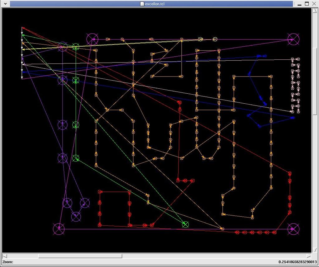
7 File Formats Professional manufacture of PCBs is typically done through the use of CAD-independent files: Gerber Files describe the copper foil layout Drill Files (often in the Excellon format) describe the location and size of holes Both are meant for direct use with automated PCB production equipment.
8 File Formats: Excellon Drill File Excellon Files provide a command sequence to a system that drills PCBs This equipment (or its computer driver) has an interpreter that receives and executes the commands in sequence. The next two slides describe the list of commands that are interpreted.
9 Source: Norme Excellon, available at accessed 12 Feb 2008 (dead link at 26 Jan 2011). Excellon file format is governed by ANSI/IPC-NC-349. % Rewind and Stop X#Y# Move and Drill T# Tool Selection M30 End of Program M00 End of Program M25 Beginning of Pattern M31 Beginning of Pattern M01 End of Pattern M02 X#Y# Repeat Pattern R#M02X#Y# Multiple Repeat Pattern M02 X#Y# M70 Swap Axis M02 X#Y# M80 Mirror Image X Axis M02 X#Y# M90 Mirror Image Y Axis M08 End of Step and Repeat N# Block Sequence Number / Block Delete
10 R#X#Y# Repeat Hole G05, G81 Select Drill Mode G04 X# Variable Dwell (ignored) G90 Absolute Mode G91 Incremental Mode G92 X#Y# Set Zero G93 X#Y# Set Zero M48 Program Header to first "%" M47 Operator Message CRT Display M71 Metric Mode M72 English-Imperial Mode Snn Spindle Speed (RPM) Fnn Z axis feed speed (IPM) Typically, only a subset of these commands are used.
11 File Formats: Excellon Drill File Example % Reset and rewind. M48 Start of header. M72 Imperial (English) Mode: units in inches T01C Tool 1 Change: to 42 mil T02C Tool 2 Change: to 86 mil T03C : T04C : T05C : T06C : T07C : T08C Tool 8 Change: 152 mil % End of Header: Drill data follows T01 Select Tool 1 (42 mil) X2120Y1112 Drill at (2120 mil,1112 mil) : (Lots of data removed) T08 Select Tool 8 (152 mil) X3645Y262 Drill at (3645 mil, 262 mil) : (Data removed) M30 End of program.
12
13 File Formats: Excellon Drill File Sample of a drilling machine doing its job:
14 File Formats: Gerber Gerber files are typically used to describe the copper foil patterns on the PCB The interpreter idea is similar to what was described for the Excellon format Since pad shapes and track sizes need to specified, many new commands are used These commands are not covered here, but a good source of information can be found in Gerber RS-274X Format User s Guide, Barco Graphics, N.V., Gent, Belgium, 1998.
15 File Formats: Gerber Much of the terminology originates from the manner in which PCBs are often made: through exposure of a photo-resist layer on a board: Aperture: a size and shape of a pad (or, if moved while on, the width of a trace and the shape of its ends). Aperture Wheel: the set of apertures available. This is analogous to the set of drills available in the Excellon Drill Rack.
16 File Formats: Gerber Dated Photoplotter
17 Manufacturing Methods There are many manufacturing methods (and hybrids) that can be used to create a board. We will take a look at three: 1. Milled PCBs usual course method 2. Professionally Manufactured PCBs 3. Hobbyist Etched PCBs
18 Manufacturing Tolerances and Constraints The PCB must be designed according to the constraints imposed by the manufacturing process. See PCB Fabrication Parameters on the course web page for a list of parameters. Recall that 1 mil = (a thousandth of an inch). Minimum and maximum board size, and feature size are of particular importance.
19 Warning! Regardless of the method of manufacture, the PCB ends up existing in the real world and needs to accept the components it is designed for. Check and double-check footprints, hole sizes and other physical features. Even the smallest of design errors will make a board difficult to use.

20 Milled PCBs Historically, this is the method that has been used the most in this course. An X-Y stage is used to guide a router bit along the contours of the PCB traces. Source: Jonathan Westhues, PCB Router, accessed 23 Jan 2008.
21 Milled PCBs The result is a copper-foil that has a minimum of copper removed in order to form the connections. The backplane that is left on the board can actually be useful for noise control if it is connected to ground appropriately. Advantages: chemical free, quick, in-house (cost) Disadvantages: no plate-through holes, usually single-sided (in this course).
22 Professionally Manufactured PCBs Board Houses such as Alberta Printed Circuit offer prototyping services. These services vary, but most use a drill, electroplate, photo-etching process. Advantages: good tolerance, multiple drill sizes, multilayer, plate-through holes. Disadvantages: cost (compared to in-house production), conforming to drill sizes can be timeconsuming, chemical-oriented.
23 Typical PCB Professional Manufacturing Process In this section, we will look at some of the equipment that is used in modern PCB production.
24 Each development stage is carried out by a dedicated piece of equipment which may form part of an assembly line. Depending on your application, note that some stages may be missing here. For instance, a tinning stage is often included after etching to reduce copper layer oxidation. A multi-layer PCB, too, requires a lamination stage to join the layers.


25 A multi-stage plate-through hole setup from Mega Electronics A raster plotter from Mega Electronics serves as a replacement to the photoplotter described earlier. This plotter is capable of creating a 5 micron spot. A laminator is used to apply the photoresist layer to the PCB. This laminator is from Mega Electronics. Source: accessed 12 Feb 2008


 are typically used for each stage")
26 UV units used to expose the photoresist on a PCB. There are many different sorts of etching, developing, and stripping setups. This one is from Mega Electronics and is a unit that sprays the chemicals over board panels, mounted inside. Different units (of the same type) are typically used for each stage described, above. Shows a board being etched. A panel that is inserted into a spray tank.


27 Etch-resist, solder masks, parts placement silkscreen legends, and even solder paste can applied to a PCB using silkscreen printing technology. Again from Mega Electronics, units such as this Production Line can be used to combine the chemical stages into a convenient unit. The operator is responsible for forwarding the PCB through the stages.
28 Hobbyist Etched Creating your own board is not too difficult! Many hobbyists choose this option. This manufacturing method will likely not be used this term; talk with the course technician if you have interest in using this approach. Advantages: potentially multi-layer, support for (larger) surface mount packages. Disadvantages: generating artwork, drilling by hand (likely), tolerances subject to operation, chemicalbased.
29 Hobbyist Solutions Follow all safety protocols! Do not flush chemicals down the drain! Save used chemicals in a clearly labelled container and turn them in to the EcoStation. If on campus, there is a chemical handling protocol that needs to be followed.
30 Hobbyist Solutions As with the professional production methods, there are many possibilities of how even a hobbyist can manufacture PCBs. A toner transfer method that gives reasonable results is described at: A video of someone going through this process can be found at: Variations: using a printer fuser instead of an iron, using a powder-based etchant, and tinning the board using solder paste and a heat gun. Please handle chemicals in a safer manner!
31 Conclusion You now have an idea of what the PCB production process involves At a professional level; and At a hobbyist level. Hopefully with this knowledge you have gained enough insight to allow the design of PCBs that are compatible with the means by which they are created.
Gerber Setup. Modified by Susan Riege on 4-Aug Parent page: WorkspaceManager Dialogs
 Gerber Setup Modified by Susan Riege on 4-Aug-2015 Parent page: WorkspaceManager Dialogs Other Related Resources Options for Project - Options Tab (Dialog) Generate Output Files (Dialog) Aperture (Dialog)
Intro PCBs. Jonathan Bachrach. September 8, EECS UC Berkeley
 Intro PCBs Jonathan Bachrach EECS UC Berkeley September 8, 2016 Last Time Introduced Nucleo-L432KC 1 Today 2 Going to talk about PCBs and Soldering wisegeek Traditional PCB CAD Design 3 schematic capture
Published on Online Documentation for Altium Products (http://www.altium.com/documentation)
") Published on Online Documentation for Altium Products (http://www.altium.com/documentation) Home > Gerber Setup A New Era for Documentation Modified by Phil Loughhead on Jun 17, 2017 The Gerber Setup dialog
Published on Online Documentation for Altium Products (http://www.altium.com/documentation) Home > Gerber Setup A New Era for Documentation Modified by Phil Loughhead on Jun 17, 2017 The Gerber Setup dialog
Page 1
 CONTENT INTRODUCTION 2 INPUT DATA FORMATS 3 INPUT DATA REQUIREMENTS 4 CLASSIFICATION 6 HOLES 8 COPPER LAYERS 10 BGAS 12 MECHANICAL LAYER 13 SOLDERMASK 15 LEGEND PRINT 17 CARBON 18 PEEL-OFF MASK 19 VIAFILL
Gerber Setup. Summary. Access. Options/Controls. General Tab. Modified by on 13-Sep Parent page: WorkspaceManager Dialogs
 Gerber Setup Old Content - visit altium.com/documentation Modified by on 13-Sep-2017 Parent page: WorkspaceManager Dialogs Summary Each Gerber file corresponds to one layer in the physical board the component
Creating another Printed Circuit Board
 Appendix C Creating another Printed Circuit Board In this chapter, we will learn the following to World Class standards: Starting with a Finished Schematic Creating the Layers for the Printed Circuit Board
Processing Gerber Files in CircuitPro
 Processing Gerber Files in CircuitPro Requirements 1. Circuit Pro version 1.5 revision 164 or higher 2. Set of Gerber Files Process Steps 1. Execute Process Planning Wizard. a. Press the process planning
Introduction to NI Multisim & Ultiboard Software version 14.1
 School of Engineering and Applied Science Electrical and Computer Engineering Department Introduction to NI Multisim & Ultiboard Software version 14.1 Dr. Amir Aslani August 2018 Parts Probes Tools Outline
Generic Multilayer Specifications for Rigid PCB s
 Generic Multilayer Specifications for Rigid PCB s 1.1 GENERAL 1.1.1 This specification has been developed for the fabrication of rigid SMT and Mixed Technology Multilayer Printed Circuit Boards (PCB's)
PCB and RF Antenna Design with automatic tool change
 MIPEC 4MILL300ATC PCB and RF Antenna Design with automatic tool change MIPEC can handle standard Single side and Double sided PCB designs, SMD, RF and various other applications. 4MILL300ATC with automatic
Getting Started in Eagle Professional Schematic Software. Tyler Borysiak Team 9 Manager
 Getting Started in Eagle 7.3.0 Professional Schematic Software Tyler Borysiak Team 9 Manager 1 Executive Summary PCBs, or Printed Circuit Boards, are all around us. Almost every single piece of electrical
Computer Numeric Control
 Computer Numeric Control TA202A 2017-18(2 nd ) Semester Prof. J. Ramkumar Department of Mechanical Engineering IIT Kanpur Computer Numeric Control A system in which actions are controlled by the direct
PCB layout tutorial MultiSim/Ultiboard
 PCB layout tutorial MultiSim/Ultiboard The basic steps in designing a PCB Paper design and prototype of the basic circuit. Identify the parts and the footprints that will be used. Make a circuit schematic,
Tutorial In Practical Circuit Board Design Ben LeVesque ECE480 Team 3 November 9 th, 2007
 utorial In Practical Circuit Board Design Ben LeVesque ECE480 eam 3 November 9 th, 2007 Keywords Circuit board, Cadence, Layout, Capture, post processing, trace capacity, trace ampacity, Via Abstract his
SOON CHIN FHONG IGNATIUS AGUNG WIBOWO PENERBIT UTHM. iii
 i ii SOON CHIN FHONG IGNATIUS AGUNG WIBOWO PENERBIT UTHM iii iv CONTENTS Preface Acknowledgment ix xiii Chapter 1 INTRODUCTION 1 What is Printed Circuit Board? 2 Printed Circuit Board Option 5 PCB CAD
Fertigungsdaten aufbereiten mit GerbTool und VisualCAM
 FlowCAD Webinar Fertigungsdaten aufbereiten mit GerbTool und VisualCAM Overview Introduction News 16.2 Gerber Format Importing Data Layer Compare DFM Analysis Modifications on existing designs artwork
Design For Manufacture
 NCAB Group Seminar no. 11 Design For Manufacture NCAB GROUP Design For Manufacture Design for manufacture (DFM) What areas does DFM give consideration to? Common errors in the documentation Good design
Wheatstone Bridge. M16C Microcontroller Strain Gauge (temperature compensation)
") Overview Eagle Version: 5.11.0 Circuit: Strain gauge amplifier for interface with a microcontroller. Time Requirements 2 + 2 + 2 hours. This three part guide is intended to provide an introduction to PCB
Overview Eagle Version: 5.11.0 Circuit: Strain gauge amplifier for interface with a microcontroller. Time Requirements 2 + 2 + 2 hours. This three part guide is intended to provide an introduction to PCB
Printed Circuit Techniques
 Experiment # 0 Printed Circuit Techniques INTRODUCTION: More than 40 years after they first appeared, the printed-circuit boards (PCBs) are still the most important means of connecting components into
PCB Fundamentals Quiz
 1. PCBs should be fabricated with layers. a. Odd Number of b. Even Number of c. Any Number of 2. Which of the following is not taken into consideration when calculating the characteristic impedance for
PCB Fundamentals Quiz
 1. PCBs should be fabricated with layers. a. Odd Number of b. Even Number of c. Any Number of Reason: Using an odd number of layers may result in board warpage. 2. Which of the following is not taken into
Autonomous Machine To Manufacture PCB and 3-D Design
 Volume 119 No. 15 2018, 961-966 ISSN: 1314-3395 (on-line version) url: http://www.acadpubl.eu/hub/ http://www.acadpubl.eu/hub/ 1 Autonomous Machine To Manufacture PCB and 3-D Design Mrs. Archana Prasanthi.
Value Stream Map Process Flow
 Value Stream Map Process Flow Pre- Locate Data Value Stream Mapping Has The Following Characteristics: It Is A Comprehensive And Detailed Graphical Document That Lists Every Business Unit, Organization,
IEEE #: March 24, Rev. A
 Texas Tech University Electrical Engineering Department IEEE Student Branch Milling Tutorial An EE s Guide to Using the Milling Machine Written by: Juan Jose Chong Photos by: David Hawronsky IEEE #: 90499216
TN008. PCB Design Guidelines for 2x2 LGA Sensors. Introduction. 2x2 LGA Package Marking
 PCB Design Guidelines for 2x2 LGA Sensors Introduction This technical note is intended to provide information about Kionix s 2 x 2 mm LGA packages and guidelines for developing PCB land pattern layouts.
DESIGN FOR MANUFACTURABILITY (DFM)
") T H A N K S F O R A T T E N D I N G OUR TECHNICAL WEBINAR SERIES DESIGN FOR MANUFACTURABILITY (DFM) Presented by: We don t just sell PCBs. We sell sleep. Cirtech EDA is the exclusive SA representative
T H A N K S F O R A T T E N D I N G OUR TECHNICAL WEBINAR SERIES DESIGN FOR MANUFACTURABILITY (DFM) Presented by: We don t just sell PCBs. We sell sleep. Cirtech EDA is the exclusive SA representative
Milling PCBs. Jonathan Bachrach. September 14, EECS UC Berkeley
 Milling PCBs Jonathan Bachrach EECS UC Berkeley September 14, 2016 Last Time 1 PCBs wisegeek Today 2 Milling PCBs CNC 3 Computerized Numeric Control Benefits 4 Automation Precision Repeatability Flexibility
EECAD s MUST List. Requests for drawing numbers MUST be submitted via the EECAD job request form at
 Customers are required to follow certain criteria for all designs whether they are ultimately done in EECAD or by the customers themselves. These criteria, approved by EES Management, are listed below:
Artwork: (A/W) An accurately scaled configuration used to produce the artwork master or production master.
 An accurately scaled configuration used to produce the artwork master or production master.") Adhesive: The material used for bonding two substrates of material together. (usually; LF of FR 0100) Adhesive Squeeze-Out: Adhesive will ooze out slightly during the lamination cycle. Annular Ring: That
Adhesive: The material used for bonding two substrates of material together. (usually; LF of FR 0100) Adhesive Squeeze-Out: Adhesive will ooze out slightly during the lamination cycle. Annular Ring: That
ECE453 Lab 5: FM Quadrature Demodulation / PCB Design Using Eagle
 ECE453 Lab 5: FM Quadrature Demodulation / PCB Design Using Eagle In this lab, you will work with your partner to design a printed circuit board for a quadrature demodulator IC and supporting components.
DIY PCB TUTORIAL. What you will need:
 DIY PCB TUTORIAL DISCLAIMER: MAKING PRINTED CIRCUIT BOARDS AT HOME INVOLVES THE USE OF DANGEROUS CHEMICALS AND POWER TOOLS. THIS TUTORIAL IS INTENDED FOR PEOPLE WHO ALREADY HAVE EXPERIENCE MAKING PRINTED
Conversational CAM Manual
 Legacy Woodworking Machinery CNC Turning & Milling Machines Conversational CAM Manual Legacy Woodworking Machinery 435 W. 1000 N. Springville, UT 84663 2 Content Conversational CAM Conversational CAM overview...
Prototype PCBs implementatio n session
 Prototype PCBs implementatio n session By: Dr. Ahmed ElShafee ١ Dr. Ahmed ElShafee, ACU : Spring 2018, EEP04 Practical Applications in Electrical ٢ photo resistive PCB ٣ Step 1 : print PCB on translucent
Lecture (03.02) PCB fabrication using. and toner thermal transferee By: Dr. Ahmed ElShafee
 PCB fabrication using. and toner thermal transferee By: Dr. Ahmed ElShafee") Lecture (03.02) PCB fabrication using photo resistive PCB and toner thermal transferee By: Dr. Ahmed ElShafee ١ Dr. Ahmed ElShafee, ACU : Spring 2017, Practical App EE IV photo resistive PCB ٢ Step 1 :
Lecture (03.02) PCB fabrication using photo resistive PCB and toner thermal transferee By: Dr. Ahmed ElShafee ١ Dr. Ahmed ElShafee, ACU : Spring 2017, Practical App EE IV photo resistive PCB ٢ Step 1 :
Step Stencil Technology
 Step Stencil Technology Greg Smith gsmith@fctassembly.com Tony Lentz tlentz@fctassembly.com Outline/Agenda Introduction Step Stencils Technologies Step Stencil Design Printing Experiment Experimental Results
PCB Layout. Date : 22 Dec 05. Prepare by : HK Sim Prepare by : HK Sim
 PCB Layout Date : 22 Dec 05 Main steps from Schematic to PCB Move from schematic to PCB Define PCB size Bring component from schematic to PCB Move the components to the desire position Layout the path
Cir cuit s 212 Lab. Lab #7 Filter Design. Introductions:
 Cir cuit s 22 Lab Lab #7 Filter Design The purpose of this lab is multifold. This is a three-week experiment. You are required to design a High / Low Pass filter using the LM38 OP AMP. In this lab, you
Fertigungsdaten bequem aufbereiten mit Cross Probe zum PCB Editor
 FlowCAD Webinar Fertigungsdaten bequem aufbereiten mit Cross Probe zum PCB Editor 14. November 2013 Introduction to VisualCAM/GerbTool Complete control over PCB designs Visual verification Analysis Optimization
courtesy Wikipedia user Wikinaut
 What's a PCB? https://learn.sparkfun.com/tutorials/pcb-basics Printed circuit board is the most common name but may also be called printed wiring boards or printed wiring cards. Before the advent of the
How to solder SMD component on Awesome PCB or any other kind of PCB.
 How to solder SMD component on Awesome PCB or any other kind of PCB. Step by step tutorial, with no steps to skip. Step 1 - What do we need? Step 2 - Fixing PCB Step 3 - Preparing for soldering Step 4
CNC PROGRAMMING WORKBOOK. Sample not for. Distribution MILL & LATHE. By Matthew Manton and Duane Weidinger
 CNC PROGRAMMING WORKBOOK MILL & LATHE By Matthew Manton and Duane Weidinger CNC Programming Workbook Mill & Lathe Published by: CamInstructor Incorporated 330 Chandos Crt. Kitchener, Ontario N2A 3C2 www.caminstructor.com
Allegro New Products - DFM / Rule Checkers
 Allegro New Products - DFM / Rule Checkers Eric / Graser 16 / Oct / 2015 Topic Allegro DFM Checker in Allegro PCB Manufacturing Option Allegro PCB Rules Developer / Checker Option PCB Design & Production
What the Designer needs to know
 White Paper on soldering QFN packages to electronic assemblies. Brian J. Leach VP of Sales and Marketing AccuSpec Electronics, LLC Defect free QFN Assembly What the Designer needs to know QFN Description:
2x2 mm LGA Package Guidelines for Printed Circuit Board Design. Figure 1. 2x2 mm LGA package marking information.
 2x2 mm LGA Package Guidelines for Printed Circuit Board Design This technical note is intended to provide information about Kionix s 2 x 2 mm LGA packages and guidelines for developing PCB land pattern
(Refer Slide Time: 00:50)
") Computer Numerical Control of Machine Tools and Processes Professor A Roy Choudhury Department of Mechanical Engineering Indian Institute of Technology Kharagpur Lecture 03 Classification of CNC Machine
Computer Numerical Control of Machine Tools and Processes Professor A Roy Choudhury Department of Mechanical Engineering Indian Institute of Technology Kharagpur Lecture 03 Classification of CNC Machine
PCB Design (with EAGLE tutorial) TA: Robert Likamwa ELEC 424, Fall 2010
 TA: Robert Likamwa ELEC 424, Fall 2010") PCB Design (with EAGLE tutorial) TA: Robert Likamwa ELEC 424, Fall 2010 Printed Circuit Boards What are they? How can I make one? 424 Project description Eagle Tutorial http://www.electronicmanufacturers.co.za/
PCB Design (with EAGLE tutorial) TA: Robert Likamwa ELEC 424, Fall 2010 Printed Circuit Boards What are they? How can I make one? 424 Project description Eagle Tutorial http://www.electronicmanufacturers.co.za/
Module 2. Milling calculations, coordinates and program preparing. 1 Pepared By: Tareq Al Sawafta
 Module 2 Milling calculations, coordinates and program preparing 1 Module Objectives: 1. Calculate the cutting speed, feed rate and depth of cut 2. Recognize coordinate 3. Differentiate between Cartesian
Block Delete techniques (also called optional block skip)
") Block Delete techniques (also called optional block skip) Many basic courses do at least acquaint novice programmers with the block delete function As you probably know, when the control sees a slash code
Block Delete techniques (also called optional block skip) Many basic courses do at least acquaint novice programmers with the block delete function As you probably know, when the control sees a slash code
Design Guide for High-Speed Controlled Impedance Circuit Boards
 IPC-2141A ASSOCIATION CONNECTING ELECTRONICS INDUSTRIES Design Guide for High-Speed Controlled Impedance Circuit Boards Developed by the IPC Controlled Impedance Task Group (D-21c) of the High Speed/High
VII PCB Fabrication. A. PCB Material
 VII PCB Fabrication A. PCB Material 1. Very early in the electronic business, we tried literally to make printed circuit boards. That is, we took an insulator (bakelite was all we had at the time) and
Published on Online Documentation for Altium Products (http://www.altium.com/documentation)
") Published on Online Documentation for Altium Products (http://www.altium.com/documentation) Главная > Controlled Depth Drilling, or Back Drilling Новая эра документации Modified by Jun Chu on Apr 11, 2017
Published on Online Documentation for Altium Products (http://www.altium.com/documentation) Главная > Controlled Depth Drilling, or Back Drilling Новая эра документации Modified by Jun Chu on Apr 11, 2017
How to Transform your 3D Printer in a CNC MILLING MACHINE
 How to Transform your 3D Printer in a CNC MILLING MACHINE How to Transform your 3D Printer in a CNC milling machine We can finally presents you a tutorial on how to modify our 3D printer K8200 to transform
527F CNC Control. User Manual Calmotion LLC, All rights reserved
 527F CNC Control User Manual 2006-2016 Calmotion LLC, All rights reserved Calmotion LLC 21720 Marilla St. Chatsworth, CA 91311 Phone: (818) 357-5826 www.calmotion.com NC Word Summary NC Word Summary A
Basic NC and CNC. Dr. J. Ramkumar Professor, Department of Mechanical Engineering Micro machining Lab, I.I.T. Kanpur
 Basic NC and CNC Dr. J. Ramkumar Professor, Department of Mechanical Engineering Micro machining Lab, I.I.T. Kanpur Micro machining Lab, I.I.T. Kanpur Outline 1. Introduction to CNC machine 2. Component
LEAN NPI AT OPTIMUM DESIGN ASSOCIATES: PART 2 WHAT IS LEAN NPI AND HOW TO ACHIEVE IT
 W H I T E P A P E R LEAN NPI AT OPTIMUM DESIGN ASSOCIATES: PART 2 WHAT IS LEAN NPI AND HOW TO ACHIEVE IT RANDY HOLT, OPTIMUM DESIGN ASSOCIATES JAMES DOWDING, MENTOR GRAPHICS w w w. o d b - s a. c o m In
NUMERICAL CONTROL.
 NUMERICAL CONTROL http://www.toolingu.com/definition-300200-12690-tool-offset.html NC &CNC Numeric Control (NC) and Computer Numeric Control (CNC) are means by which machine centers are used to produce
ECE 477 Digital Systems Senior Design Project. Module 11 Board Assembly and Soldering Techniques
 2011 by D. G. Meyer ECE 477 Digital Systems Senior Design Project Module 11 Board Assembly and Soldering Techniques Outline I ve got my board, now what? Which end of this thing gets hot? Flux is your friend.
Preliminary Ideas: PTFE-Based Microwave Laminates and Making Prototypes
 Appendix I Preliminary Ideas: PTFE-Based Microwave Laminates and Making Prototypes A1.1 PTFE Laminates PTFE is a popular abbreviation representing a very useful high frequency material, whose chemical
AltiumLive 2017: Creating Documentation for Successful PCB Manufacturing
 AltiumLive 2017: Creating Documentation for Successful PCB Manufacturing Julie Ellis TTM Field Applications Engineer Thomas Schneider Field Applications Engineer 1 Agenda 1 Complexity & Cost 2 3 4 5 6
Printed circuit boards-solder mask design basics
 Printed circuit boards-solder mask design basics Standards Information on the use of solder mask is contained in IPC-SM-840C Qualification and Performance of Permanent Solder Mask. The specification is
DESIGNING A PATCH ANTENNA FOR DOPPLER SYSTEMS
 DESIGNING A PATCH ANTENNA FOR DOPPLER SYSTEMS Doppler Requirements for Antennas Range Determines power consumption Defines frequency band R max = 4 P t GσA e 4π 2 S min Narrow Bandwidth Tolerance range
A range of techniques has been devised to quantify the amount of misregistration present in a laminated panel:
 Controlling Multilayer Registration Jim Dermody Operations Technology, Inc. T H E P R 0 B L E M How does one optimize the multilayer fabrication process for best registration of layers and drill patterns?
Inkjet resist inks. Krishna Balantrapu
 Inkjet resist inks Krishna Balantrapu OUTLINE Conventional Vs. Inkjet-Cost Savings Inkjet Material Design Inkjet Equipment-Lunaris Future work 2 DOW-R&D DRIVERS FOR NEW PRODUCT DEVELOPMENT Technology Need
ScaleRCHelis.com V Light Controller Kit
 Thank you for purchasing the ScaleRCHelis.com V1.1 450 Light Controller Kit. This is something you can build in under a hour with some simple soldering equipment. Your kit will include all the parts necessary
PCB Fabrication Processes Brief Introduction
 PCB Fabrication Processes Brief Introduction AGS-Electronics, Ph: +1-505-550-6501 or +1-505-565-5102, Fx: +1-505-814-5778, Em: sales@ags-electronics.com, Web: http://www.ags-electronics.com Contents PCB
Electronics Technology and Robotics III Final ROV Construction
 Electronics Technology and Robotics III Final ROV Construction Administration: o Prayer Review: o The final Remotely Operated Vehicle (ROV) assembly is made up of some of the components that we have already
When the machine makes a movement based on the Absolute Coordinates or Machine Coordinates, instead of movements based on work offsets.
 Absolute Coordinates: Also known as Machine Coordinates. The coordinates of the spindle on the machine based on the home position of the static object (machine). See Machine Coordinates Absolute Move:
ATTRIBUTES STANDARD ADVANCED
 TECHNOLOGY MATRIX 2017 ATTRIBUTES STANDARD ADVANCED Line/Space.005 /.005.003 /.003 Copper Foil. Oz. Min/Max ½ / 2 3 / 8 Pad Size Int. (dia over Drill).014.008 Pad Size Ext. (dia over Drill).012.008 Drill-to-Metal
Table of Contents. Preface 9 Prerequisites 9. Key Concept 1: Know Your Machine From A Programmer s Viewpoint 13. Table of Contents
 Preface 9 Prerequisites 9 Basic machining practice experience 9 Controls covered 10 Limitations 10 Programming method 10 The need for hands -on practice 10 Instruction method 11 Scope 11 Key Concepts approach
Today s Flexible Multi-purpose Inspection Systems: Process Set-up, Process Control and Product Traceability All in One Platform
 Today s Flexible Multi-purpose Inspection Systems: Process Set-up, Process Control and Product Traceability All in One Platform By Jeffrey Rupert, Director of Advanced Technology & Business Development,
Testing of Flexible Metamaterial RF Filters Implemented through Micromachining LCP Substrates. Jonathan Richard Robert Dean Michael Hamilton
 Testing of Flexible Metamaterial RF Filters Implemented through Micromachining LCP Substrates Jonathan Richard Robert Dean Michael Hamilton Metamaterials Definition Metamaterials exhibit interesting properties
PCB Supplier of the Best Quality, Lowest Price and Reliable Lead Time. Low Cost Prototype Standard Prototype & Production Stencil PCB Design
 The Best Quality PCB Supplier PCB Supplier of the Best Quality, Lowest Price Low Cost Prototype Standard Prototype & Production Stencil PCB Design Visit us: www. qualiecocircuits.co.nz OVERVIEW A thin
Getting Started. Terminology. CNC 1 Training
 CNC 1 Training Getting Started What You Need for This Training Program This manual 6 x 4 x 3 HDPE 8 3/8, two flute, bottom cutting end mill, 1 Length of Cut (LOC). #3 Center Drill 1/4 drill bit and drill
and Engineering Graphics
 SOLIDWORKS 2018 and Engineering Graphics An Integrated Approach Randy H. Shih SDC PUBLICATIONS Better Textbooks. Lower Prices. www.sdcpublications.com Powered by TCPDF (www.tcpdf.org) Visit the following
CNC :DSTV & Pipe profiling. Aaron Leacock
 CNC :DSTV & Pipe profiling Aaron Leacock CNC Overview of DSTV file Example of a File Common setup options Scribing options Tips and tricks DSTV Viewers DXF plate (Punch overrun) Pipe profiling download
Computer Aided Manufacturing
 Computer Aided Manufacturing CNC Milling used as representative example of CAM practice. CAM applies to lathes, lasers, waterjet, wire edm, stamping, braking, drilling, etc. CAM derives process information
Altium I (Circuit Design + Layout)
") Altium I (Circuit Design + Layout) ELEC391 Summer T1 2018 Contents PCB Design support for ELEC391 PCB design flow How to install Altium Designer 2016 Understanding Altium Designer Walk-through example
Altium I (Circuit Design + Layout) ELEC391 Summer T1 2018 Contents PCB Design support for ELEC391 PCB design flow How to install Altium Designer 2016 Understanding Altium Designer Walk-through example
WIDE FORMAT SOFTWARE CUTTERS/PLOTTERS THERMAL PRINT AND CUT ROUTERS
 WIDE FORMAT SOFTWARE CUTTERS/PLOTTERS THERMAL PRINT AND CUT ROUTERS EQUIPMENT 1. 8 6 6. N GLANTZ NGLANTZ.COM WIDE FORMAT ROLL TO ROLL INTEGRATED PRINT AND CUT UNITS Mimaki Solvent/Eco-Solvent Printer &
LED Field Strength Indicator Kit
 LED Field Strength Indicator Kit Description The Field Strength Indicator kit from Qrpkits.com provides a visual way to monitor RF fields through the brightness of an LED. It will respond to RF fields
DEPARTMENT OF MECHANICAL ENGINEERING
 SCSVMV UNIVERSITY DEPARTMENT OF MECHANICAL ENGINEERING SUBJECT NAME : SUBJECT CODE : MANUFACTURING TECHNOLOGY-II EBM4DT055 QUESTION BANK UNIT-1 1. What is Grinding? 2. Briefly classify the Grinding Process.
Trade of Toolmaking. Module 6: Introduction to CNC Unit 2: Part Programming Phase 2. Published by. Trade of Toolmaking Phase 2 Module 6 Unit 2
 Trade of Toolmaking Module 6: Introduction to CNC Unit 2: Part Programming Phase 2 Published by SOLAS 2014 Unit 2 1 Table of Contents Document Release History... 3 Unit Objective... 4 Introduction... 4
Sample VA Technical Documentation Assessments
 Sample 243-251-VA Technical Documentation Assessments EVALUATION OF ASSESSMENT TOOLS USED TO MEASURE ACHIEVEMENT OF IET COURSE COMPETENCIES Please attach copies of all assessment tools used in this section
TCLAD: TOOLS FOR AN OPTIMAL DESIGN
 TCLAD: TOOLS FOR AN OPTIMAL DESIGN THINGS TO CONSIDER WHEN DESIGNING CIRCUITS Many factors come into play in circuit design with respect to etching, surface finishing and mechanical fabrication processes;
SOLIDWORKS 2015 and Engineering Graphics
 SOLIDWORKS 2015 and Engineering Graphics An Integrated Approach Randy H. Shih SDC PUBLICATIONS Better Textbooks. Lower Prices. www.sdcpublications.com Powered by TCPDF (www.tcpdf.org) Visit the following
Chapter 12: Electronic Circuit Simulation and Layout Software
 Chapter 12: Electronic Circuit Simulation and Layout Software In this chapter, we introduce the use of analog circuit simulation software and circuit layout software. I. Introduction So far we have designed
DigiSpeed DC-03. Isolated Control Voltage Generator User s Guide. PCB: DC-03 V3.0 Firmware: Ver: 3.0 Mach3: Ver: 1.84
 DigiSpeed DC-03 - Users Guide Page 1 Updated: 29. April 2009 DigiSpeed DC-03 Isolated Control Voltage Generator User s Guide PCB: DC-03 V3.0 Firmware: Ver: 3.0 Mach3: Ver: 1.84 DigiSpeed DC-03 - Users
5 TIPS FOR SPECIFYING PCB HOLE SIZE TOLERANCE
 One of the more forgotten topics in PCB design are the holes through which components are mounted. Specifying the tolerance of hole dimensions in PCB fabrication ensures proper fit of plated-through-hole
South Bay Circuits. Manufacturability Guidelines. Printed Circuit Boards FOR. South Bay Circuits, Inc. 99 N. McKemy Ave Chandler, AZ 85226
 Manufacturability Guidelines FOR Printed Circuit Boards South Bay Circuits, Inc. 99 N. McKemy Ave Chandler, AZ 85226 GL-0503B By: Edward Rocha Dear Customer, The intention of this document is to provide
DigiSpeed-GX DC-03. Isolated Control Voltage Generator User s Guide. DigiSpeed-GX PCB Ver:2.0 Firmware Ver: 1.0 Mach3 Ver: 1.84
 DigiSpeed-GX - Users Guide Page 1 Updated: 15. January 2009 DigiSpeed-GX DC-03 Isolated Control Voltage Generator User s Guide DigiSpeed-GX PCB Ver:2.0 Firmware Ver: 1.0 Mach3 Ver: 1.84 DigiSpeed-GX -
CNC Machinery. Module 4: CNC Programming "Turning" IAT Curriculum Unit PREPARED BY. August 2009
 CNC Machinery Module 4: CNC Programming "Turning" PREPARED BY IAT Curriculum Unit August 2009 Institute of Applied Technology, 2009 2 Module 4: CNC Programming "Turning" Module 4: CNC Programming "Turning"
Photoplotter FP 8000/8000 XL Instruction manual
 MEGA ELECTRONICS LIMITED., Mega House, Grip Industrial Estate, Linton, Cambridge, CB21 4XN Telephone: +44 (0) 1223 893900 Fax: +44 (0) 1223 893894 email: sales@megauk.com web: www.megauk.com Photoplotter
FYS4260/FYS9260: Microsystems and Electronics Packaging and Interconnect Printed Circuit Boards
 FYS4260/FYS9260: Microsystems and Electronics Packaging and Interconnect Printed Circuit Boards Interior detail from an Apple iphone 5 printed circuit board Learning objectives Understand how printed wiring/circuit
Visual Imaging in the Electronic Age
 Visual Imaging in the Electronic Age ART 2107, ARCH 3702, CS 1620, ENGRI 1620 3D Printing November 6, 2014 Prof. Donald P. Greenberg dpg5@cornell.edu Types of 3D Printers Selective deposition printers
Processing parameters of PCBs manufactured by TS PCB Techno-Service S.A.
 Processing parameters of PCBs manufactured by TS PCB Techno-Service S.A. Last update: jh 26.09.2017 Table of contents 1. Processing parameters of PCB materials... 3 1.1. Applied laminate types... 3 1.2.
Technology Flexible Printed Circuits Rev For latest information please visit
 Options and Characteristics Online calculation On explicit enquiry Quantity 1 pieces up to 1m² total area 1piece to mass production Number of layers 1 to 2 layers up to 6 layers Material thickness 0,05mm
TN019. PCB Design Guidelines for 3x2.5 LGA Sensors Revised. Introduction. Package Marking
 PCB Design Guidelines for 3x2.5 LGA Sensors Revised Introduction This technical note is intended to provide information about Kionix s 3 x 2.5 mm LGA packages and guidelines for developing PCB land pattern
Motion Manipulation Techniques
 Motion Manipulation Techniques You ve already been exposed to some advanced techniques with basic motion types (lesson six) and you seen several special motion types (lesson seven) In this lesson, we ll
Design for Manufacturing
 2 Design for Manufacturing This chapter will address the fabrication process of the PCB and the requirements of the manufacturer. Manufacturers are separated by their limitations or constraints into categories
Electronics Design Checklist (C) 2003 Hank Wallace
 2003 Hank Wallace") Electronics Design Checklist (C) 2003 Hank Wallace This is a checklist for electronics designers. The idea is for engineers and technicians to share experiences and create a detailed checklist, which the
Electronics Design Checklist (C) 2003 Hank Wallace This is a checklist for electronics designers. The idea is for engineers and technicians to share experiences and create a detailed checklist, which the
Applications of Maskless Lithography for the Production of Large Area Substrates Using the SF-100 ELITE. Jay Sasserath, PhD
 Applications of Maskless Lithography for the Production of Large Area Substrates Using the SF-100 ELITE Executive Summary Jay Sasserath, PhD Intelligent Micro Patterning LLC St. Petersburg, Florida Processing