K band Focal Plane Array: Mechanical and Cryogenic Considerations Steve White,Bob Simon, Mike Stennes February 20, 2008 COLD ELECTRONICS
|
|
|
- Anna Stanley
- 5 years ago
- Views:
Transcription
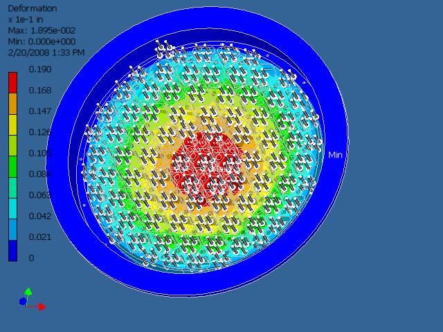
1 K band Focal Plane Array: Mechanical and Cryogenic Considerations Steve White,Bob Simon, Mike Stennes February 20, 2008 CRYOGENICS AND DEWAR DESIGN The dewar outside dimension must be less than the 36 diameter hole of the GBT receiver room turret with all external components conforming to this footprint. Although no explicit weight limitations are imposed, the ever increasing load on the feed arm is a concern, justifying efforts to minimize the total weight. Table 1 gives the weight totals estimated or measured from existing components. The top cover is designed to minimize the deflection created from pressure differential induced stresses and moments from internal components when tilted. Unlike the other receivers the top plate and turret mount are integrated into one machined piece of Alcoa MIC-6 cast aluminum. The cover will be machined with the feed mounts and a strength rib, reducing the deformation to a maximum of An Inventor drawing which generated the stress analysis is shown in Figure 1. COLD ELECTRONICS The fully populated cryogenic dewar load must not exceed the lift capabilities of a Model 1020 refrigerator. This restriction is based on the number of cryogenic lines available (six) and the abilities of the cryogenic laboratory to service and provide spares for the receiver. A larger refrigerator would consume the entire mass flow capabilities of a compressor and subsequently reduce the number of cooled receivers available. In order to ensure adequate cooling and temperature stability, operation in the middle of the load performance curve is desirable as shown in Figure 2. Most of the thermal loading is easily calculated and given in Table 2. As this juncture, the approach that mitigates the thermal contraction of the components, reduces the thermal load, and meets the stability specification is under investigation. Estimated thermal coefficient of expansion considering aluminum components with TCE of 22 x 10^-6 m/m K and length L = 0.5 m, ΔT = 285º K gives 3.1 mm. With order centimeter wavelengths this change is significant. Previous designs use long stainless steel coax to solve these problems. This technique has known reliabilility problems and complicates the design with added coax to waveguide transitions. A possible solution is ss waveguide with flexible bends, or a telescoping wg design that compensates for the contraction (Described below). Our intention is to prototype each in a cryogenic test dewar with repeated thermal cycling. The stability will be measured with a noise source and lab spectrometer.
2 K-BAND FOCAL PLANE ARRAY RECEIVER TABLE OF WEIGHTS LAST UPDATE: 2/20/2008 Weight Required Total Required Total Component: each for weight for weight Notes pounds 7 pixel 7 pixel 61 pixel 61 pixel Feedhorn Actual Vacuum window assembly Estimate Thermal transition, less G inventor model G-10 standoff inventor model Circular to square transition Estimate Phase shifter Estimate 45 degree twist Actual OMT Alum, 1lb each if brass Noise source module Estimate Isolator Actual Amplifier Actual Output wg assembly inventor model Dewar top plate Inventor model Dewar bottom plate " 6061-T6, inventor model Dewar cylinder SS304, inventor model CTI 1020 refrigerator Actual Cold straps Estimate 15K cold plate al,.125 thick, inventor model Top radiation shield plate al,.0625, estimate Floating heat shield al,.0625, estimate 70 radiation shield al,.0625, estimate Charcoal trap x11 inch, inventor model Common dewar wiring cu wires, 18" long, 36awg ma Dewar heaters Actual Temperature sensors Actual Vacuum valve assembly " manual MDC valve DV6R vacuum gage Actual Common hardware Estimate Downconverter Estimate from Matt LO module Estimate LO to downconverter cables cu, 12" long,qty 120, with sma Cardcage Estimate, current cardcage Computer interface Current MCB interface Radome assembly Inventor model Lifting rings Estimate Receiver support rails Estimate Dewar feedthru connectors Estimate Amplifier bias distribution Estimate RFI gaskets Estimate Totals General notes: Possibly use tin plated aluminum.085 coax for LO Fabricate LO distribution using alum housings Computer interface and cardcage unknown at this time Wiring outside the dewar not included. To be determined May need refrigerator extension tube. To be determined May need receiver support structure for transport. To be determined
3
4 ThermalLoadTotals.xls Date:12/17/ Stage Refrigerator Load 2nd Stage Refrigerator Load Thermal Load Analysis: Pixels: Radiative Conductive * * Radiativ e * * Conductiv e * * [W] [W] [W] [W] Shield Top Cover 6.05 Bottom Cover 6.05 Thermal Gap SS Waveguide(35/5 cm) G-10 Standoff HEMT Amplifier Manganin Bias (32 awg) I*R Man. Wire Loss Noise Module Total Total TOTAL 7 Pixels TOTAL 61 Pixels Page 1


5
6 WR-42 waveguide slip-joint Introduction The densely-integrated RFE pixel configuration of the GBT K-Band Focal Plane Array does not lend itself well to the use of conventional stress-relieving methods. As a possible alternative solution to the adverse effects of thermal contraction and expansion, R. Norrod has proposed a telescoping waveguide assembly, or slip joint, in which a thin-wall (0.010-inch wall thickness) stainless-steel waveguide is fit into a slightly larger guide, and sealed electrically by an EMI gasket. The slip joint would be located in the dewar output waveguides, near the vacuum window. This configuration is shown schematically in figure 1. M. Stennes presents here the results of a preliminary EM analysis of the proposed K-band waveguide slip joint. The frequency of operation has been defined as 18.0 < f < 27.5 GHz. Total thermal contraction of the RFE assembly has been estimated as inch. The initial CST EM model was simplified as follows: PEC conductors, including the wire-mesh EMI gasket Vacuum in waveguide, as opposed to air. Foam plug (behind vacuum window) tan δ = , ε r = 1.06 Direction of movement, when temperature is decreased SS WR42 GAP EMI GASKET GAP DEPTH POLYSTYRENE VACUUM WINDOW POLYSTYRENE THICKNESS WINDOW THICKNESS MATCHING IRIS (IF NECESSARY) Figure 3. Diagram of waveguide slip joint. The waveguide slip joint was modeled using CST Microwave Studio. The initial model was simplified, in that it did not incorporate a waveguide iris, and it did not take into account any irregularities in the gap (see definition of GAP in figure 1), except for the special case of a lateral offset in which two of the four WG walls were in contact.
7 The EM model was built with a inch gap between the outer wall of the SS waveguide and the inner wall of the fixed WG which holds the foam plug and vacuum window. The gap width was chosen as a reasonable estimate, considering mechanical tolerances of both the SS waveguide, and the machined section containing the vacuum window. The foam plug is thick, and the distance from the inner surface of the plug to the bottom of the gap is equal to d inch. The primary aim of this preliminary work was to predict the effect of the air gap depth on return loss, and also to consider the case in which there is a lateral offset of one waveguide with respect to the other, making two of the four waveguide walls in direct contact. Analysis Results Resonances occur at frequencies corresponding to gap depths equal to odd multiples of one-quarter of a guide wavelength. These are present in both cases: the resonances remain after the waveguides are shifted relative to each other effectively closing the gap on two sides of the joint. Vacuum EMI Gasket Gap Depth Figure 4. A cut plane view of the waveguide slip joint, illustrating the gap depth.
8 Figure 5. S11 as a function of gap depth, with a constant gap width of inch on four walls. Note: Gap depth = (d 130) Figure 6. S11 for varying gap depth, this time without foam plug.
9 Figure 7. Illustration of the effect of large scale variations in gap depth on s11. Figure 8. S11 as a function of gap depth, with two of the waveguide wall in direct contact. Conclusions Initial EM analysis confirms that the proposed waveguide slip joint can give a return loss of -20 db or better. However, an air gap between the sliding SS waveguide and the fixed 300K section can introduce frequency resonances if the gap is sufficiently deep. The resonant frequencies occur for gap depths that are odd multiples of a quarter-wavelength. Since the expected magnitude of the thermal contraction is a significant fraction of a quarter-wavelength, the gap depth should be designed for minimum depth. Setting the gap depth at at room temperature, for instance, would produce a gap depth of nearly zero inches when cooled due to thermal contraction.
10 There are many parameter-space combinations, and tuning options that have not yet been investigated. Plans are underway to further parameterize the model, and add tuning elements. A knitted wire mesh EMI gasket is suggested, such as the 20-X1110t offered by Teknit.
EVLA Front-End CDR. EVLA Ka-Band (26-40 GHz) Receiver
 Receiver") EVLA Front-End CDR EVLA Ka-Band (26-40 GHz) Receiver 1 EVLA Ka-Band Receiver Overview 1) General Description 2) Block Diagram 3) Noise & Headroom Model 4) Feed & Thermal Gap 5) RF Tree - Phase-Shifter
EVLA Front-End CDR EVLA Ka-Band (26-40 GHz) Receiver 1 EVLA Ka-Band Receiver Overview 1) General Description 2) Block Diagram 3) Noise & Headroom Model 4) Feed & Thermal Gap 5) RF Tree - Phase-Shifter
Cu 0.37 Brass Cu 0.37 Brass
 To: From: EDGES MEMO #148 MASSACHUSETTS INSTITUTE OF TECHNOLOGY HAYSTACK OBSERVATORY WESTFORD, MASSACHUSETTS 01886 October 7, 2014 Telephone: 781-981-5400 Fax: 781-981-0590 EDGES Group Alan E.E. Rogers
Diseño del Criostato del Receptor de Banda Ancha
 Diseño del Criostato del Receptor de Banda Ancha José Manuel Serna, Beatriz Vaquero, Félix Tercero, Samuel López Informe Técnico IT-CDT 2015-18 [Los desarrollos descritos en este informe técnico han sido
ALMA Interferometer and Band 7 Cartridge
 ALMA Interferometer and Band 7 Cartridge B7 Cartridge designed, assembled and tested by: S. Mahieu, D. Maier (mixer team lead), B. Lazareff (now at IPAG) G. Celestin, J. Chalain, D. Geoffroy, F. Laslaz,
A Turnstile Junction Waveguide Orthomode Transducer for the 1 mm Band
 A Turnstile Junction Waveguide Orthomode Transducer for the 1 mm Band Alessandro Navarrini, Richard L. Plambeck, and Daning Chow Abstract We describe the design and construction of a waveguide orthomode
NATIONAL RADIO ASTRONOMY OBSERVATORY CHARLOTTESVILLE, VIRGINIA. ELECTRONICS DIVISION INTERNAL REPORT No. 275 CRYOGENIC, HEMT, LOW-NOISE RECEIVERS
 NATIONAL RADIO ASTRONOMY OBSERVATORY CHARLOTTESVILLE, VIRGINIA ELECTRONICS DIVISION INTERNAL REPORT No. 275 CRYOGENIC, HEMT, LOW-NOISE RECEIVERS FOR 1.3 TO 43 GHz RANGE S. WEINREB M. W. POSPIESZALSKI R.
Ku-Band Receiver System for SHAO
 Ku-Band Receiver System for SHAO Overview Brent Willoughby July 2014 Atacama Large Millimeter/submillimeter Array Expanded Very Large Array Robert C. Byrd Green Bank Telescope Very Long Baseline Array
Dinesh Micro Waves & Electronics
 Wave Guide Components RECTANGULAR WAVE GUDES Dinesh Microwaves and Electronics manufacturers of high power waveguide in the microwaves industry, this experience had resulted in designing, manufacturing
Detector Systems. Graeme Carrad
 Detector Systems Graeme Carrad November 2011 The Basic Structure of a typical Radio Telescope Antenna Receiver Conversion Digitiser Signal Processing / Correlator They are much the same CSIRO. Radiotelescope
L-BAND COPLANAR SLOT LOOP ANTENNA FOR INET APPLICATIONS
 L-BAND COPLANAR SLOT LOOP ANTENNA FOR INET APPLICATIONS Jeyasingh Nithianandam Electrical and Computer Engineering Department Morgan State University, 500 Perring Parkway, Baltimore, Maryland 5 ABSTRACT
Optimizing Microwave Signal Transmissions In Extreme Cryogenic Environments Times Microwave Systems SiO2 Products
 Optimizing Microwave Signal Transmissions In Extreme Cryogenic Environments Times Microwave Systems Products Martin Winkler Product Manager Times Microwave Systems 358 Hall Avenue Wallingford, CT 06492
Homebrew your Omnidirectional INMARSAT-C Antenna
 Homebrew your Omnidirectional INMARSAT-C Antenna In this short article we are going to look into the construction details of an old commercial INMARSAT-C Antenna. The purpose of this document is to serve
Atacama Large Millimeter/submillimeter Array Expanded Very Large Array Robert C. Byrd Green Bank Telescope Very Long Baseline Array
 Atacama Large Millimeter/submillimeter Array Expanded Very Large Array Robert C. Byrd Green Bank Telescope Very Long Baseline Array A Planar OMT for the 8-12 GHz Receiver Front-End Michael Stennes October
9 Element Yagi for 2304 MHz
 9 Element Yagi for 2304 MHz Steve Kavanagh, VE3SMA Design Dipole-based Yagi designs for 2304 MHz are rare, partly because they are a bit tricky to build and partly because the loop yagi has completely
Maas 16-way Wilkinson Divider Measurements A. Harris 2 Jan 2002
 Maas 16-way Wilkinson Divider Measurements A. Harris 2 Jan 2002 Measurement and calibration Steve Maas designed a 16-way Wilkinson power divider on a 1 1 alumina substrate that is 10 mils thick. For this
Turnstile Junction Orthomode Transducer An option for EVLA X-Band Receiver X-Band OMT Design Review Meeting; AOC, Socorro; October1, 2009
 Turnstile Junction Orthomode Transducer An option for EVLA X-Band Receiver X-Band OMT Design Review Meeting; AOC, Socorro; October1, 2009 Sivasankaran Srikanth, Miles Solatka & Michael Meek Scientist/Research
NATIONAL RADIO ASTRONOMY OBSERVATORY L/C/X BAND CRYOGENIC RECEIVER FRONT-END NO. 2 FOR RVARD RADIO ASTRONOMY STATION, FORT DAVIS, TEX
 NATIONAL RADIO ASTRONOMY OBSERVATORY Green Ba n k, West V irginia Electronics D ivision Internal Report No. 238 L/C/X BAND CRYOGENIC RECEIVER FRONT-END NO. 2 FOR RVARD RADIO ASTRONOMY STATION, FORT DAVIS,
Mixer-Preamp to Receiver Interface Considerations for ALMA Band 6
 ALMA Memo 344 18 January 2001 Mixer-Preamp to Receiver Interface Considerations for ALMA Band 6 A. R. Kerr National Radio Astronomy Observatory Charlottesville, VA 22903, USA The NRAO CDL is preparing
EVLA Receiver Issues. EVLA Advisory Committee Meeting, March 19-20, 2009
 EVLA Receiver Issues EVLA Advisory Committee Meeting, March 19-20, 2009 Robert Hayward - Systems Engineer for EVLA Front-Ends Gordon Coutts - Microwave Engineer, Front-End Group Sri Srikanth - Scientist/Research
SMA - 50 Ohm Connectors
 For Flexible Cable Straight Crimp Type Plug - Captivated Contact CABLE TYPE RG-178/U, 196 1.20 +.025 f (GHz) 0-12.4 GHz 142-0402-001 142-0402-006 RG-161/U, 174,188, 316 RG-188 DS, RG-316 DS RG-58/U, 141,
ngvla Advanced Cryocoolers For ngvla NATIONAL RADIO ASTRONOMY OBSERVATORY Larry D Addario, Caltech ngvlaworkshop, Socorro, 2017 June 26
 NATIONAL RADIO ASTRONOMY OBSERVATORY Advanced Cryocoolers For ngvla Larry D Addario, Caltech ngvlaworkshop, Socorro, 2017 June 26 ngvla Outline How cold do we need to get? Tutorial on cryocoolers (just
A Low Noise GHz Amplifier
 A Low Noise 3.4-4.6 GHz Amplifier C. Risacher*, M. Dahlgren*, V. Belitsky* * GARD, Radio & Space Science Department with Onsala Space Observatory, Microtechnology Centre at Chalmers (MC2), Chalmers University
EMC Simulation of Consumer Electronic Devices
 of Consumer Electronic Devices By Andreas Barchanski Describing a workflow for the EMC simulation of a wireless router, using techniques that can be applied to a wide range of consumer electronic devices.
Radio Telescope Receivers
 Radio Telescope Receivers Alex Dunning 25 th September 2017 CSIRO ASTRONOMY AND SPACE SCIENCE A radio receiver is an electronic device that receives radio waves and converts the information carried by
Low Noise Amplifiers for 2304, 3456, 5760, and MHz using the ATF PHEMT by Al Ward WB5LUA
 Low Noise Amplifiers for 2304, 3456, 5760, and 10368 MHz using the by Al Ward INTRODUCTION The Hewlett-Packard device is described in a series of low noise amplifiers for 2304, 3456, 5760, and 10368 MHz.
arxiv:physics/ v1 [physics.optics] 28 Sep 2005
![arxiv:physics/ v1 [physics.optics] 28 Sep 2005](/thumbs/91/105523130.jpg "arxiv:physics/ v1 [physics.optics] 28 Sep 2005") Near-field enhancement and imaging in double cylindrical polariton-resonant structures: Enlarging perfect lens Pekka Alitalo, Stanislav Maslovski, and Sergei Tretyakov arxiv:physics/0509232v1 [physics.optics]
Near-field enhancement and imaging in double cylindrical polariton-resonant structures: Enlarging perfect lens Pekka Alitalo, Stanislav Maslovski, and Sergei Tretyakov arxiv:physics/0509232v1 [physics.optics]
47 GHz Waveguide Harmonic Mixer
 47 GHz Waveguide Harmonic Mixer These slides present an evolution of harmonic mixer construction ideas. The first slides depict the first harmonic mixer construction details and the later slides depict
A Noise-Temperature Measurement System Using a Cryogenic Attenuator
 TMO Progress Report 42-135 November 15, 1998 A Noise-Temperature Measurement System Using a Cryogenic Attenuator J. E. Fernandez 1 This article describes a method to obtain accurate and repeatable input
EC6011-ELECTROMAGNETICINTERFERENCEANDCOMPATIBILITY
 EC6011-ELECTROMAGNETICINTERFERENCEANDCOMPATIBILITY UNIT-3 Part A 1. What is an opto-isolator? [N/D-16] An optoisolator (also known as optical coupler,optocoupler and opto-isolator) is a semiconductor device
VGOS MEMO #042 MASSACHUSETTS INSTITUTE OF TECHNOLOGY HAYSTACK OBSERVATORY WESTFORD, MASSACHUSETTS August 22, 2016
 To: From: Subject: VGOS MEMO #042 MASSACHUSETTS INSTITUTE OF TECHNOLOGY HAYSTACK OBSERVATORY WESTFORD, MASSACHUSETTS 01886 Space Geodesy Project August 22, 2016 Ganesh Rajagopalan and Chris Eckert Failure
Couplers for Project X. S. Kazakov, T. Khabiboulline
 Couplers for Project X S. Kazakov, T. Khabiboulline TTC meeting on CW-SRF, 2013 Requirements to Project X couplers Cavity SSR1 (325MHz): Cavity SSR2 (325MHz): Max. energy gain - 2.1 MV, Max. power, 1 ma
Full-Waveguide Band Orthomode Transducer for the 3 mm and 1 mm Bands. 2 Fabrication and Testing of 3 mm Band OMT
 14th International S y mposium on Space Terahertf. Technology Full-Waveguide Band Orthomode Transducer for the 3 mm and 1 mm Bands Gopal Narayanan l, and Neal Erickson Department of Astronomy, University
Optics for the 90 GHz GBT array
 Optics for the 90 GHz GBT array Introduction The 90 GHz array will have 64 TES bolometers arranged in an 8 8 square, read out using 8 SQUID multiplexers. It is designed as a facility instrument for the
Design of Controlled RF Switch for Beam Steering Antenna Array
 PIERS ONLINE, VOL. 4, NO. 3, 2008 356 Design of Controlled RF Switch for Beam Steering Antenna Array M. M. Abusitta, D. Zhou, R. A. Abd-Alhameed, and P. S. Excell Mobile and Satellite Communications Research
Essex County College - West Essex Campus Addition And Renovations dlb # / SECTION EXPANSION FITTINGS AND LOOPS FOR HVAC PIPING
 SECTION 230516 - EXPANSION FITTINGS AND LOOPS FOR HVAC PIPING PART I - GENERAL 1.1 RELATED DOCUMENTS A. Drawings and general provisions of the Contract, including General and Supplementary Conditions and
REVIEW OF HIGH POWER CW COUPLERS FOR SC CAVITIES. S. Belomestnykh
 REVIEW OF HIGH POWER CW COUPLERS FOR SC CAVITIES S. Belomestnykh HPC workshop JLAB, 30 October 2002 Introduction Many aspects of the high-power coupler design, fabrication, preparation, conditioning, integration
MICROWAVE WAVEGUIDES and COAXIAL CABLE
 MICROWAVE WAVEGUIDES and COAXIAL CABLE In general, a waveguide consists of a hollow metallic tube of arbitrary cross section uniform in extent in the direction of propagation. Common waveguide shapes are
MICROWAVE MICROWAVE TRAINING BENCH COMPONENT SPECIFICATIONS:
 Microwave section consists of Basic Microwave Training Bench, Advance Microwave Training Bench and Microwave Communication Training System. Microwave Training System is used to study all the concepts of
Estimation of the Loss in the ECH Transmission Lines for ITER
 Estimation of the Loss in the ECH Transmission Lines for ITER S. T. Han, M. A. Shapiro, J. R. Sirigiri, D. Tax, R. J. Temkin and P. P. Woskov MIT Plasma Science and Fusion Center, MIT Building NW16-186,
Precision Thermistor Sensors
 Precision Thermistor Sensors For Laboratory Applications ON-400 Series U For Use in Laboratory or Other High-Accuracy Applications U Rugged Construction Can Be Used for Short Term Water and Soil Readings
Millikelvin measurement platform for SQUIDs and cryogenic sensors
 Cryoconference 2010 Millikelvin measurement platform for SQUIDs and cryogenic sensors M. Schmidt, J. Beyer, D. Drung, J.-H. Storm Physikalisch-Technische Bundesanstalt, Abbe Str. 2-22, 10587 Berlin, Germany
Conduct-o-Seal Oriented Wire in Silicone Gasket Material
 East Coast Shielding Oriented wire in silicone gasketing material is a combination EMI shield and environmental pressure seal. Produced on location, this product is fabricated with individual wires positioned
DESIGN AND FABRICATION OF CAVITY RESONATORS
 &2@?%3 DESIGN AND FABRICATION OF CAVITY RESONATORS CHAPTER 3 DESIGN AND FABRICATION OFCAVITY RESONATORS 3.1 Introduction In the cavity perturbation techniques, generally rectangular or cylindrical waveguide
NATIONAL RADIO ASTRONOMY OBSERVATORY GREEN BANK, WEST VIRGINIA ECCOFOAM AS A DEWAR WAVEGUIDE VACUUM WINDOW. Richard F. Bradley and Roger D.
 NATIONAL RADIO ASTRONOMY OBSERVATORY GREEN BANK, WEST VIRGINIA ELECTRONICS DIVISION TECHNICAL NOTE NO. 125 Title: ECCOFOAM AS A DEWAR WAVEGUIDE VACUUM WINDOW Author(s): Richard F. Bradley and Roger D.
AVN Training HartRAO 2016
 AVN Training HartRAO 2016 Microwave 1 Overview Introduction to basic components used in microwave receivers. Performance characteristics of these components. Assembly of components into a complete microwave
PIPE/CONDUIT SUPPORTS
 PIPE/CONDUIT SUPPORTS Pipe/Conduit Clamps...102-105 Unicushion... 106 Pipe & Tubing (Cush-A-Clamp ) Clamps...107-110 Pipe Hangers... 111 Pipe Rollers...111-112 Pipe Brackets... 113 Reference Tables...114-120
Antennas Prof. Girish Kumar Department of Electrical Engineering Indian Institute of Technology, Bombay. Module 2 Lecture - 10 Dipole Antennas-III
 Antennas Prof. Girish Kumar Department of Electrical Engineering Indian Institute of Technology, Bombay Module 2 Lecture - 10 Dipole Antennas-III Hello, and welcome to todays lecture on Dipole Antenna.
Operating & Maintenance Instructions 320 Dome Blowing Unit
 Operating & Maintenance Instructions 320 Dome Blowing Unit Table of Contents 1. On Delivery... 2 2. General Information... 3 3. Dome Blowing Technique... 4 4. Other Shapes... 6 5. Machine Maintenance...
Concept
 Concept squaretop Spring loaded Concept Squaretop rises from the surface for access to 4 power outlets and two telecom plates, populated with the connectors you specify. Specifications: All steel construction.
Measurement Notes. Note 53. Design and Fabrication of an Ultra-Wideband High-Power Zipper Balun and Antenna. Everett G. Farr Farr Research, Inc.
 Measurement Notes Note 53 Design and Fabrication of an Ultra-Wideband High-Power Zipper Balun and Antenna Everett G. Farr Farr Research, Inc. Gary D. Sower, Lanney M. Atchley, and Donald E. Ellibee EG&G
Recent work on Hall A magnets Present and future Jay Benesch January 2018
 Recent work on Hall A magnets Present and future Jay Benesch January 2018 1 Sources All of the information contained herein can be found in much more detail in the following Tech Notes: 16-043 (SoLID),
KS CONICAL ANTENNA AND WAVEGUIDE SYSTEM DESCRIPTION
 BEU SYSTEM PRACTICES AT&TCa Standard SECTION 402-422-100 Issue 1, October 1979 MICROWAVE ANTENNAS KS-2 1972 CONICAL ANTENNA AND WAVEGUIDE SYSTEM DESCRIPTION CONTENTS I. GENERAL...........1 PAGE 2. INTRODUCTION.........
Designing an MR compatible Time of Flight PET Detector Floris Jansen, PhD, Chief Engineer GE Healthcare
 GE Healthcare Designing an MR compatible Time of Flight PET Detector Floris Jansen, PhD, Chief Engineer GE Healthcare There is excitement across the industry regarding the clinical potential of a hybrid
Physical Test Setup for Impulse Noise Testing
 Physical Test Setup for Impulse Noise Testing Larry Cohen Overview Purpose: Use measurement results for the EM coupling (Campbell) clamp to determine a stable physical test setup for impulse noise testing.
Anne-Laure Fontana, Catherine Boucher, Yves Bortolotti, Florence Cope, Bastien Lefranc, Alessandro Navarrini, Doris Maier, Karl-F.
 Multi-beam SIS Receiver Development Anne-Laure Fontana, Catherine Boucher, Yves Bortolotti, Florence Cope, Bastien Lefranc, Alessandro Navarrini, Doris Maier, Karl-F. Schuster & Irvin Still Institut t
4. Superconducting sector magnets for the SRC 4.1 Introduction
 4. Superconducting sector magnets for the SRC 4.1 Introduction The key components for the realization for the SRC are: the superconducting sector magnet and the superconducting bending magnet (SBM) for
Omnidirectional Antenna Vertical Polarization Indoor and outdoor use
 db Omnidirectional Antenna and outdoor use 17 27 Omni 17 27 6 2dBi 8 41 N female Connector position Bottom or top 17 27 MHz SWR < 1.8 2 dbi Intermodulation IM < 15 dbc (2 x 4 dbm carrier) ertical 5 W (at
SMA 50 Ohm Connectors Alphabetical Index INCHES (MILLIMETERS) CUSTOMER DRAWINGS AVAILABLE ON REQUEST
 CUSTOMER DRAWINGS AVAILABLE ON REQUEST") SMA 50 Ohm Connectors Alphabetical Index SMA Connectors - 50 Ohm Bulkhead Mount... 20 Custom Feedthroughs... 48 Dummy Loads... 37 End Launch... 16 Field Replaceable... 28 Flexible Cable... 8 In-Series
SMA 50 Ohm Connectors Alphabetical Index SMA Connectors - 50 Ohm Bulkhead Mount... 20 Custom Feedthroughs... 48 Dummy Loads... 37 End Launch... 16 Field Replaceable... 28 Flexible Cable... 8 In-Series
High Power RF MEMS Switch Technology
 High Power RF MEMS Switch Technology Invited Talk at 2005 SBMO/IEEE MTT-S International Conference on Microwave and Optoelectronics Conference Dr Jia-Sheng Hong Heriot-Watt University Edinburgh U.K. 1
7.2.8 Frequency sensitivity
 7.2.8 Frequency sensitivity To evaluate the effect of frequency error on the antenna performance, I also calculated the radiation patterns for the 16-slot antenna at 9.0 GHz and 11.736 GHz. The resulting
Sensor and Simulation Notes. Note 505. December Development of the Impulse Slot Antenna (ISA) and Related Designs
 and Related Designs") Sensor and Simulation Notes Note 55 December 25 Development of the Impulse Slot Antenna (ISA) and Related Designs W. Scott Bigelow, Everett G. Farr, and Leland H. Bowen Farr Research, Inc. William D. Prather
Sensor and Simulation Notes Note 55 December 25 Development of the Impulse Slot Antenna (ISA) and Related Designs W. Scott Bigelow, Everett G. Farr, and Leland H. Bowen Farr Research, Inc. William D. Prather
CAPACITIVE SENSORS. Series KS. Key-Features:
 CAPACITIVE SENSORS Series KS Key-Features: Content: Introduction Applications...2 Technical Data Sensor Heads...3 Technical Drawing...4 Sensor Cabels...5 1 Channel Electronics...6 Description Electronics
Sole Fitness E95 Elliptical Trainer TurnKey Delivery and Setup Training
 Sole Fitness E95 Elliptical Trainer TurnKey Delivery and Setup Training Delivery Requirements Ground delivery Inside delivery to customer-specified location Unpack and assemble machine, and remove packing
A Folding 11-Element Yagi for 432 MHz
 A Folding 11-Element Yagi for 432 MHz Steve Kavanagh, VE3SMA, October 2015 1. Introduction For portable VHF/UHF operation I have found it convenient at times to have some antennas which fold up quickly
Design, Development and Testing of RF Window for C band 250 kw CW Power Klystron
 Available online www.ejaet.com European Journal of Advances in Engineering and Technology, 2016, 3(6): 26-30 Research Article ISSN: 2394-658X Design, Development and Testing of RF Window for C band 250
Spiderbeam Balun Construction Guide
 BALUN CONSTRUCTION GUIDE Ver. 1.0 1 The components of the Balun Kit are in a plastic bag. Most of the components are inside the plastic case of the balun. The aluminum U-profile and the RG-142 Teflon Coax
Physically and Electrically Large Antennas for Antenna Pattern Measurements and Radar Cross Section Measurements in the Upper VHF and UHF bands
 Physically and Electrically Large Antennas for Antenna Pattern Measurements and Radar Cross Section Measurements in the Upper VHF and UHF bands Vince Rodriguez, PhD Product Manager, Antennas ETS-Lindgren,
INSTRUCTION MANUAL ORDER NO. V3R MODEL V3R. Collinear Gain Vertical for MHz
 ORDER NO. V3R MODEL V3R Collinear Gain Vertical for 216-225 MHz INSTRUCTION MANUAL General Description The new Hy-Gain V3R VHF antenna is a collinear 5/8-wave omnidirectional vertical antenna for the 216-225
Planar Transmission Line Technologies
 Planar Transmission Line Technologies CMB Polarization Technology Workshop NIST/Boulder Edward J. Wollack Observational Cosmology Laboratory NASA Goddard Space Flight Center Greenbelt, Maryland Overview
LE/ESSE Payload Design
 LE/ESSE4360 - Payload Design 4.3 Communications Satellite Payload - Hardware Elements Earth, Moon, Mars, and Beyond Dr. Jinjun Shan, Professor of Space Engineering Department of Earth and Space Science
Times Microwave Systems Hermetically Sealed Assemblies
 SCOPE This Specification details the Electrical, Mechanical and Environmental Characteristics of Times Microwave Systems MILTECH 480.48 Diameter Hermetically Sealed Coaxial Transmission Lines. This product
A IVE-BAND, TWO-ELEMENT H QUAD
 A IVE-BAND, TWO-ELEMENT H QUAD Two quad designs are described in this article, both nearly identical. One was constructed by KC6T from scratch, and the other was built by Al Doig, W6NBH, using modified
Field Instrument Cable. Electrical Noise
 Field Instrument Cable Electrical Noise 1 Electrical Noise Instrument Cables are Susceptible to 4 Types of Noise: Static Magnetic Cross-Talk Common Mode 2 Static Noise Static Noise is caused by an electric
BRNO UNIVERSITY OF TECHNOLOGY
 BRNO UNIVERSITY OF TECHNOLOGY VYSOKÉ UČENÍ TECHNICKÉ V BRNĚ FACULTY OF ELECTRICAL ENGINEERING AND COMMUNICATION DEPARTMENT OF RADIO ELECTRONICS FAKULTA ELEKTROTECHNIKY A KOMUNIKAČNÍCH TECHNOLOGIÍ ÚSTAV
Dielectric Filled Printed Gap Waveguide for Millimeter Wave Applications
 Dielectric Filled Printed Gap Waveguide for Millimeter Wave Applications Jing Zhang A Thesis In the Department of Electrical and Computer Engineering Presented in Partial Fulfillment of the Requirements
KU- BAND TEMPERATURE COMPENSATED HIGH POWER MULTIPLEXERS S. Lundquist, M. Yu, D. Smith, W. Fitzpatrick COM DEV, Cambridge, CANADA
 AIAA 2002-1992 KU- BAND TEMPERATURE COMPENSATED HIGH POWER MULTIPLEXERS S. Lundquist, M. Yu, D. Smith, W. Fitzpatrick COM DEV, Cambridge, CANADA 20 th AIAA International Communication Satellite Systems
The Low-Noise, Integrated Transformer Helium-4 Dipstick Insert
 The Low-Noise, Integrated Transformer Helium-4 Dipstick Insert Sang Lin Chu Georgia Institute Of Technology 837 State Street N.W. Atlanta, GA 30332 gte813m@prism.gatech.edu, sanglinchu@hotmail.com December
Electrical Design of Narrow Band Filters. Giuseppe Macchiarella Polytechnic of Milan, Italy Electronic and Information Department
 Electrical Design of Narrow Band Filters Giuseppe Macchiarella Polytechnic of Milan, Italy Electronic and Information Department Introduction The design of a narrow band microwave filter starts with the
ALMA Band 1. Charles Cunningham and Stéphane Claude. IRMMW-THZ 2005, Williamsburg. IRMMW-THZ 2005, Williamsburg
 ALMA Band 1 Charles Cunningham and Stéphane Claude Canadian Users - ALMA Canadian LRP 2010 The Atacama Large Millimetre Array is the top priority in LRP2000 The Atacama Large Millimetre Array (ALMA) is
MIL-C-17 Standard RF Coaxial Cable Low Loss & Ultra Low Loss RF Microwave Cable ANTENNA & TEST Cable up to 26.5 GHz
 MIL-C-17 Standard RF Coaxial Cable Low Loss & Ultra Low Loss RF Microwave Cable ANTENNA & TEST Cable up to 26.5 GHz Low Loss Low Density PTFE Dielectric RF Microwave Coaxial Cable Silver Plated Copper
400 (±2,5 V/ V/ ,3% V4A
 LVDT Inductive Position Transducer - Hydraulic Series Series Hydraulic position measurement in hydraulic cylinders of machine controls ranges 10...300 mm temperature -40...+150 C (sensors) 0...+60 C (external
Application Note 5011
 MGA-62563 High Performance GaAs MMIC Amplifier Application Note 511 Application Information The MGA-62563 is a high performance GaAs MMIC amplifier fabricated with Avago Technologies E-pHEMT process and
Model VB-23FM 2-Meter 3-Element Beam
 308 Industrial Park Road Starkville, MS 39759 USA Ph: (662) 323-9538 FAX: (662) Model VB-23FM 2-Meter 3-Element Beam [ INSTRUCTION MANUAL Figure 1 Overall View and Boom Detail GENERAL DESCRIPTION This
Roman Pots. Marco Oriunno SLAC, PPA. M.Oriunno, SLAC
 Roman Pots Marco Oriunno SLAC, PPA The Roman Pot technique 1. The Roman Pot, an historically successful technique for near beam physics: ISR, SPS, TEVATRON, RICH, DESY 2. A CERN in-house technology: ISR,
EVLA Receivers PDR. (4m, P,) L, S, C BAND RECEIVERS. AuthorDaniel (Mert) Mertely
 L, S, C BAND RECEIVERS. AuthorDaniel (Mert) Mertely") EVLA Receivers PDR (4m, P,) L, S, C BAND RECEIVERS Daniel (Mert) Mertely 1 Trx Projections EVLA RX FREQ RANGES AND OP TEMPS: REQUIRED vs. PROJECTED BND FRQ REQ CURNT CURNT CALC IDR RANGE Tsys (2) Tsys
EVLA Receivers PDR (4m, P,) L, S, C BAND RECEIVERS Daniel (Mert) Mertely 1 Trx Projections EVLA RX FREQ RANGES AND OP TEMPS: REQUIRED vs. PROJECTED BND FRQ REQ CURNT CURNT CALC IDR RANGE Tsys (2) Tsys
Influence of Temperature Variations on the Stability of a Submm Wave Receiver
 Influence of Temperature Variations on the Stability of a Submm Wave A. Baryshev 1, R. Hesper 1, G. Gerlofsma 1, M. Kroug 2, W. Wild 3 1 NOVA/SRON/RuG 2 DIMES/TuD 3 SRON / RuG Abstract Radio astronomy
Integrated Optics and Photon Counting Detectors: Introducing
 Integrated Optics and Photon Counting Detectors: Introducing µ-spec Harvey Moseley Dominic Benford, Matt Bradford, Wen-Ting Hsieh,Thomas Stevenson, Kongpop U- Yen, Ed Wollack and Jonas Zmuidzinas Jan.
The shunt capacitor is the critical element
 Accurate Feedthrough Capacitor Measurements at High Frequencies Critical for Component Evaluation and High Current Design A shielded measurement chamber allows accurate assessment and modeling of low pass
Application Note 5012
 MGA-61563 High Performance GaAs MMIC Amplifier Application Note 5012 Application Information The MGA-61563 is a high performance GaAs MMIC amplifier fabricated with Avago Technologies E-pHEMT process and
ALMA Band-1: Key Components, Cartridge Design, and Test Plan
 ALMA Band-1: Key Components, Cartridge Design, and Test Plan Yuh-Jing Hwang, Chau-Ching Chiong, Yue-Fang Kuo, Ted Huang, Doug Henke, Marian Pospieszalski, Nicolas Reyes, Ciska Kemper, and Paul Ho ASIAA,
Altoids Tin Filters. Paul Wade W1GHZ 2014
 Altoids Tin Filters Paul Wade W1GHZ 2014 w1ghz@arrl.net Several years ago, I described a series of "Multiband Microwave Transverters for the Rover - Simple and Cheap " (www.w1ghz.org), with several later
Performance Analysis of Different Ultra Wideband Planar Monopole Antennas as EMI sensors
 International Journal of Electronics and Communication Engineering. ISSN 09742166 Volume 5, Number 4 (2012), pp. 435445 International Research Publication House http://www.irphouse.com Performance Analysis
Study Of Phasing Distribution Characteristics Of Reflectarray Antenna Using Different Resonant Elements
 Study Of Phasing Distribution Characteristics Of Reflectarray Antenna Using Different Resonant Elements M.Y. Ismail 1* and M. F. M. Shukri 1 1 Faculty of Electrical and Electronic Engineering Universiti
A Folding 5-Element Yagi for 144 MHz
 A Folding 5-Element Yagi for 144 MHz Steve Kavanagh, VE3SMA, April 2017 1. Introduction I have found antennas which fold up quickly to take less space in the car to be useful in VHF/UHF portable operating.
Development Status of KSTAR LHCD System
 Development Status of KSTAR LHCD System September 24, 2004 Y. S. Bae,, M. H. Cho, W. Namkung Plasma Sheath Lab. Department of Physics, Pohang University of Science and Technology LHCD system overview Objectives
Dual-Band Printed Inverted-F Antenna with a Nested Structure
 Progress In Electromagnetics Research Letters, Vol. 61, 1 6, 216 Dual-Band Printed Inverted-F Antenna with a Nested Structure Takuichi Hirano * and Junichi Takada Abstract A dual-band printed inverted-f
Conduit measured transfer impedance and shielding effectiveness (typically achieved in the RS103 and CS114 tests)
") Conduit measured transfer impedance and shielding effectiveness (typically achieved in the RS3 and CS4 tests) D. A. Weston K. McDougall conduitse.doc 5-2-27 The data and information contained within this
Conduit measured transfer impedance and shielding effectiveness (typically achieved in the RS3 and CS4 tests) D. A. Weston K. McDougall conduitse.doc 5-2-27 The data and information contained within this
High-Power Directional Couplers with Excellent Performance That You Can Build
 High-Power Directional Couplers with Excellent Performance That You Can Build Paul Wade W1GHZ 2010 w1ghz@arrl.net A directional coupler is used to sample the RF energy travelling in a transmission line
INDUCTIVE TRI-BAND DOUBLE ELEMENT FSS FOR SPACE APPLICATIONS
 Progress In Electromagnetics Research C, Vol. 18, 87 101, 2011 INDUCTIVE TRI-BAND DOUBLE ELEMENT FSS FOR SPACE APPLICATIONS D. Ramaccia and A. Toscano Department of Applied Electronics University of Rome
Precision Folding Technology
 Precision Folding Technology Industrial Origami, Inc. Summary Nearly every manufacturing process has experienced dramatic improvements in accuracy and productivity as well as declining cost over the last