How to build a Cracklebox. Red Wierenga Brooklyn College Center for Computer Music October 13, 2015
|
|
|
- Lynne Marilyn Nelson
- 6 years ago
- Views:
Transcription
1 How to build a Cracklebox Red Wierenga Brooklyn College Center for Computer Music October 13, 2015
2 What s a Cracklebox?
3 What s a Cracklebox? The Cracklebox was developed by Michel Waisvisz and others at STEIM in the early 1970s. By experimenting with touching parts of radio circuits, Waisvisz discovered one could play a circuit like a musical instrument without having to know how the circuit worked. The player s fingers touch conductive pads and the player becomes part of the circuit, based on an obsolete opamp. See for more history.
4 What does a Cracklebox sound like? Here s an improvisation by Josh Rutner for Cracklebox, radio, bird call, and metronome, featuring a Cracklebox I made him:
5 Sounds cool, but can I just buy it instead of making one? Why, yes, indeed you can! STEIM sells Crackleboxes for $63 plus 18 shipping (as of October 2015) here: store.kagi.com/cgi-bin/store.cgi?storeid=5lz_live But wait this is Building Electronic Musical Instruments, so you have to build one.

6 OK, how do I build one? You can order a Crackle Pack Kit from STEIM: crackle-hack/
7 OK, how do I build one? Or you can find a schematic online and build it on perfboard Here s a schematic from

8 OK, how do I build one? Note: although it says you must use a 709 op-amp, it is obsolete and can be replaced with an equivalent opamp like an NTE909D. Note that while the 709 had 8 pins, the NTE909D has 14; consult a data sheet to be sure you understand the pinout. I used this schematic and perfboard to build this Cracklebox:
 and had it manufactured by OSH Park (https://oshpark.")
9 PCB I ve made it easier for you: I designed a PCB (printed circuit board) layout with EAGLE ( and had it manufactured by OSH Park (
10 Schematic Here s the schematic. Note that not all component values are on the PCB, so consult this schematic. I ve added an optional PAD7.
11 Parts Here are the parts in your kit: 2.7nF ceramic disc capacitor (C3) 10nF ceramic disc capacitors (2: C1 and C2) 100nF ceramic disc capacitor (C4) 100uF polarized electrolytic capacitor (C5) 1M resistor (R1) BC547 NPN transistors (2: Q1 and Q2) BC557 PNP transistors (2: Q3 and Q4) NTE909D opamp IC (IC1) 14-pin DIP IC socket 8 Ohm 1W mylar speaker SPDT mini toggle switch 9V battery holder Cigar box
12 Parts Here are the parts organized by component label: R1: 1M resistor (R1) C1: 10nF ceramic disc capacitor C2: 10nF ceramic disc capacitor C3: 2.7nF ceramic disc capacitor C4: 100nF ceramic disc capacitor C5: 100uF polarized electrolytic capacitor Q1: BC547 NPN transistor Q2: BC547 NPN transistor Q3: BC557 PNP transistor Q4: BC557 PNP transistor IC1: NTE909D opamp 14-pin DIP IC socket 8 Ohm 1W mylar speaker SPDT mini toggle switch 9V battery holder Cigar box
13 Parts
14 Note the capacitor codes: 272=27 and 2 zeros = 2700pF = 2.7nF. 103=10 and 3 zeros = 10000pF = 10nF Also, note the polarity of the polarized electrolytic capacitor. The negative leg is shorter, and there is a stripe with - markings on the negative side


15 First place the resistor in the location marked R1 and solder it. I usually clip the leads after soldering.


16 Next place the IC socket in the holes surrounding the area designated IC1. Place the socket so that the notch is to the left when looking at the PCB with the text right-side up. Bending the corner pins helps keep the socket in place while you solder. Solder all the pins.

 and solder it (ignore the color of the wire")
17 Cut a 5 or 6 length of wire, strip both ends, place one end in the hole labeled SPK+ and solder it Place the battery holder s black wire in the hole labeled - (right below SPK+ ) and solder it (ignore the color of the wire in the photo)

18 Now let s add the ceramic capacitors. C1 and C2=10nF, so the capacitor will be labeled 103. C3=2.7nF, so it will be labeled 272. C4=100nF, so it will be labeled 104.

19 Now let s add the transistors. It s a good idea to start with the transistors closer to the center of the board and do Q1 last. Very important: check which transistors are BC547 and which are BC557! Q1 and Q2=BC547; Q3 and Q4=BC557. Also very important: in general, be absolutely sure you orient the transistors correctly, and in general don t trust diagrams on PCBs or standard pinouts. Check the schematic and use a multimeter to test the transistor s pinout. Many circuits have failed on account of incorrect transistor orientation. Luckily, I ve checked these transistors for you, so the orientation matches the PCB diagram.

20 Now add the bipolar electrolytic capacitor, C5. Note that there is a small - next to the hole for the negative leg. Be sure to orient the capacitor so that the negative leg goes into this hole.

21 Cut a 5 or 6 length of wire and strip both ends. Solder one end to the SPK- hole and the another to the unused speaker terminal.

22 Cut another wire and strip both ends. Solder one end to the hole labeled + and the other to the center terminal of the switch. (Note, a SPST switch would also work). Solder the battery holder s red wire to one of the outer terminals of the switch.

23 Cut six lengths of wire, each around 5 or 6, strip both ends of each, and solder one end of each to one of the six pads labeled PAD1-PAD6. Note: the Cracklebox has six contacts, but we can add a seventh. If you want, solder a seventh wire to the hole labeled PAD7.

24 Being very careful, gently press the IC s legs inward slightly so that it will fit in the socket. The IC, like most ICs, has a notch at one end, next to which there is a small circle. The pin next to this circle is pin 1. Make sure you orient the IC correctly, so that the notch matches the notch in the socket, which in turn matches the notch indicated on the PCB. Once all the legs look like they ll fit into the socket, gently but firmly press the IC into the socket, making sure that all legs are firmly in the socket.
25 Time for testing! Place a charged 9V battery into the battery holder. Use your fingers to simultaneously touch several of the Cracklebox s exposed wires. If you try touching several combinations of several wires and don t hear any sound, flip the power switch and try again. If you don t hear anything, check the orientation of the transistors, bipolar electrolytic capacitor, and IC. Examine the PCB for any solder bridges or loose joints. Make sure the IC is fully in the socket. We ll review more testing procedures in class as needed.
26 Finishing Our priority in this class is making sure that everyone can get their Cracklebox working. Once you have it working, you ll need to mount everything in an enclosure. Decide what you want to use for electrodes and where you want them. Decide where you want the speaker and power switch. Decide where inside the enclosure you will mount the PCB and battery holder.
27 Finishing Decide what you want to use for electrodes. Anything conductive can work. I like using a washer/bolt combination. Find bolts, drill appropriately sized holes in the top of the cigar box (6 or 7, depending on whether or not you re using the additional PAD7), and screw the bolts into place. Next, solder the ends of each exposed wire to a washer. You may need to use a very high temperature on your soldering iron. Place something like a piece of scrap wood underneath the washer while you solder it so that it does not burn the surface on which you are working. When you ve soldered all the wires to washers, place each washer on a bolt and then tighten the nut so that the washer and bolt are both firmly in place.
.")
28 Soldering to a washer Place some scrap wood underneath (notice the burn mark).
29 Finishing Once you ve decided where to mount the speaker, drill several holes in the cigar box, position the speaker inside the box underneath these holes, and use a glue gun to affix the speaker to the box. Drill an appropriately sized hole for the power switch and screw it into place. Use screws, standoffs, and nuts to mount the PCB inside the box. Remove the battery from the battery holder and use screws and nuts to mount the battery holder.

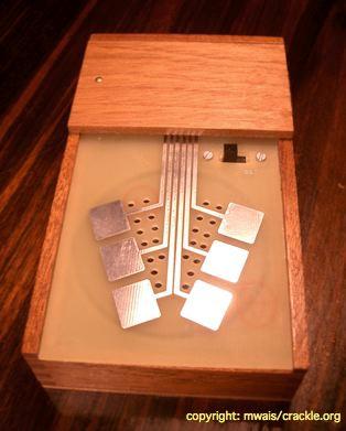
30 Finishing Inside lid of the cigar box, showing a possible arrangement of body contacts, power switch, and PCB. The body contacts here are machine screws and nuts with washers connected to the PCB s pads.

31 Finishing The finished Cracklebox
32 Ideas for further exploration Add another contact The original Cracklebox has 6 contacts. Note that the schematic shows pin 5 of the 709 unconnected. I ve added a PAD7 to the PCB for you to experiment with adding a contact to this pin.
33 Ideas for further exploration Add an LED The schematic shown above adds an LED (indicated in red) to the circuit. I haven t tried this out. In the schematic the LED is inserted between C2 and the battery s negative terminal. It s not obvious that there would be enough current to drive the LED. It may make more sense to add the LED between +9V (after the switch!) and GND with a current limiting resistor in series with the positive leg of the LED.
34 Ideas for further exploration Add an output jack Tom Bugs of BugBrand suggests using a TL071 as a non-inverting opamp buffer and a transformer to help isolate the circuit from the outside world; see
35 Ideas for further exploration Make a pseudo-crackle Synth According to crackle.org, The Crackle Synthesizer consisted of the components of 3 Crackleboxes. These could be linked by touching special conductive pads. Potentiometers were used to control the amount of controllability of this instrument. 'Minimum control' meant that the Crackle Synthesizer would easily play on its own for hours.
36 Ideas for further exploration Make a pseudo-crackle Synth Here s a video of Waisvisz playing a Crackle Synth in 2004: list=pldadv0n29s_gqvow H_YvKr2TtTA23ewNI&t=398

37 Ideas for further exploration Make a pseudo-crackle Synth Nico Bes went through the STEIM archives and didn t find information on the Crackle Synth s construction; he indicated that it consisted of three oscillators with destabilization circuitry. Try building three Crackleboxes and linking their pads together through potentiometers.

38 Ideas for further exploration Make a pseudo-crackle Synth James Fei has done something similar and added a modular aspect; he writes: Four Kraakdoos circuits each have six points brought out to a breadboard, allowing for changes in circuit values, bridging, and feedback between the four circuits. For more information see his article Real-Time Prototyping in Live Electronic Music: A Modular Crackle Instrument.

39 Ideas for further exploration Make a pseudo-crackle Synth STEIM s Kristina Andersen is (as of October 2015) working on the project Remaking Crackle, researching the Crackle Synth ( stimuleringsfonds.nl/en/ latest/grants_issued/ remaking_crackle/)
40 Ideas for further exploration Apply the same principle to other circuits Although the Cracklebox relies on the peculiarities of the LM709 for its distinctive behavior and sound, we can experiment with other amplifier ICs, for instance the LM386. Here s a modification of the LM386-based amplifier circuit we read about in Nicolas Collins s book. Try breadboarding it.

41 Ideas for further exploration Research other designs Tom Bugs of BugBrand has created a series of devices called Weevils that use touch points. See, for example, bugbrand_old/pages/ sounddevices.htm
BYOC Vibrato Kit Instructions BA662A version
 BYOC Vibrato Kit Instructions BA662A version Please read these instructions very thoroughly before building even if you are an experience builder. Because of the layout, there is a certain order which
Mono Amplifier. LM386 Headphone Amp
 Mono Amplifier LM386 Headphone Amp Layout On/Off Switch - cuts power to the circuit Mono Input Jack: use either L or R or solder together Schematic Step 1 - Parts List 1.) R1-10ohm Resistor - Brown Black
BYOC Vibrato Kit Instructions BA6110 version
 BYOC Vibrato Kit Instructions BA6110 version Please read these instructions very thoroughly before building even if you are an experience builder. Because of the
Value Location Qty Potentiometers C1M Distortion 1 A10k Volume 1. Footswitch 3PDT SW1 1. Jacks 1/4 Mono 2 DC Power 1
 Distortion BUILD INSTRUCTIONS Thank you for your purchase of our Distortion+ kit! We have completely redesigned our entire line of kits to be the most user friendly, while still maintaining their same
5W Mono Amplifier Kit
 5W Mono Amplifier Kit Kit Construction Before you start assembling your kit there are a couple of important things you must do. FIRST read through these instructions entirely before you start construction
Guitarpedalkits.com Overdrive Pedal Build Instructions
 Page 1 Guitarpedalkits.com Overdrive Pedal Build Instructions Follow the instructions in this guide to build your very own DIY overdrive pedal from GuitarPedalKits.com. If you re a first time builder,
LDB-1 Kit Instructions Page 1 of 8
 LDB-1 Kit Instructions Page 1 of 8 Important Information Congratulations and thank you for your purchase of the LDB-1 Little Drummer Boy Analog Drum Machine Kit! Before you start, please read the enclosed
Build Your Own Clone Li l Echo Kit Instructions
 Build Your Own Clone Li l Echo Kit Instructions Warranty: BYOC, Inc. guarantees that your kit will be complete and that all parts and components will arrive as described, functioning and free of defect.
4ms SCM Breakout. Kit Builder's Guide for PCB v2.1 4mspedals.com
 4ms SCM Breakout Kit Builder's Guide for PCB v2.1 4mspedals.com Shuffling Clock Multiplier Breakout This guide is for building a Shuffling Clock Multiplier Breakout module (SCMBO) version 2.1 from the
Value Location Qty Transistors 2N5485 Q1, Q2, 4 Q3, Q4 2N5087 Q5 1. Trim Pots 250k VTRIM 1. Potentiometers C500k Speed 1. Toggle Switch On/On Vibe 1
 P-90 BUILD INSTRUCTIONS Thank you for your purchase of our P-90 kit! We have completely redesigned our entire line of kits to be the most user friendly, while still maintaining their same great sound!
Penrose Quantizer Assembly Guide
 Penrose Quantizer Assembly Guide Schematic and BOM The schematic can be found here: www.sonic-potions.com/public/penrosequantizerschematic.pdf The BOM is available at google docs: Link to BOM Prepare the
FM RADIO KIT ESSENTIAL INFORMATION. Version 2.0 GET IN TUNE WITH THIS
 ESSENTIAL INFORMATION BUILD INSTRUCTIONS CHECKING YOUR PCB & FAULT-FINDING MECHANICAL DETAILS HOW THE KIT WORKS GET IN TUNE WITH THIS FM RADIO KIT Version 2.0 Build Instructions Before you start, take
Build Your Own Clone Li l Reverb Kit Instructions
 Build Your Own Clone Li l Reverb Kit Instructions Warranty: BYOC, Inc. guarantees that your kit will be complete and that all parts and components will arrive as described, functioning and free of defect.
Build Your Own Clone Mouse Kit Instructions
 Build Your Own Clone Mouse Kit Instructions Warranty: BYOC, Inc. guarantees that your kit will be complete and that all parts and components will arrive as described, functioning and free of defect. Soldering,
Build Your Own Clone Crown Jewel Kit Instructions
 Build Your Own Clone Crown Jewel Kit Instructions Warranty: BYOC, Inc. guarantees that your kit will be complete and that all parts and components will arrive as described, functioning and free of defect.
KASTLE v1.5 - Assembly Guide
 last update: 14. 12. 2017 KASTLE v1.5 - Assembly Guide bastl-instruments.com INTRODUCTION Welcome to the assembly guide for the Kastle kit - mini modular synthesizer. It is suitable for beginners. It is
Build Your Own Clone 27V Boost Kit Instructions
 Build Your Own Clone 27V Boost Kit Instructions Warranty: BYOC, Inc. guarantees that your kit will be complete and that all parts and components will arrive as described, functioning and free of defect.
Build Your Own Clone Classic Phaser Kit Instructions
 Build Your Own Clone Classic Phaser Kit Instructions Warranty: BYOC, Inc. guarantees that your kit will be complete and that all parts and components will arrive as described, functioning and free of defect.
MONO AMPLIFIER KIT ESSENTIAL INFORMATION. Version 3.0 CREATE YOUR OWN SPEAKER DOCK WITH THIS
 ESSENTIAL INFORMATION BUILD INSTRUCTIONS CHECKING YOUR PCB & FAULT-FINDING MECHANICAL DETAILS HOW THE KIT WORKS CREATE YOUR OWN SPEAKER DOCK WITH THIS MONO AMPLIFIER KIT Version 3.0 Build Instructions
STEP 0 Prepare the Materials.
 How to Build a Germanium Fuzz Guitar Effect. This document will guide you to build and test your Germanium Fuzz guitar pedal. With all the materials on hand, it takes around 2-4 hours to build it. Try
Build Your Own Clone Li l Analog Chorus Kit Instructions
 Build Your Own Clone Li l Analog Chorus Kit Instructions Warranty: BYOC, Inc. guarantees that your kit will be complete and that all parts and components will arrive as described, functioning and free
Build Your Own Clone The Swede Kit Instructions
 Build Your Own Clone The Swede Kit Instructions Warranty: BYOC, Inc. guarantees that your kit will be complete and that all parts and components will arrive as described, functioning and free of defect.
Warm Tube Clock. Before we start, please make sure that you have all required parts that come for the main board :
 Warm Tube Clock Assembly Instructions for the main board Introduction Congratulations on your purchase of OSH Nixie Tube Clock. In this document you will see all steps you need to follow in order to successfully
MICROGRANNY v2.1 - Assembly Guide
 last update: 9. 5. 2017 MICROGRANNY v2.1 - Assembly Guide bastl-instruments.com INTRODUCTION Welcome to the assembly guide for the MicroGranny kit. MicroGranny is a monophonic granular sampler by Bastl
Build Your Own Clone Kuzco Jr. Kit Instructions
 Build Your Own Clone Kuzco Jr. Kit Instructions Warranty: BYOC, Inc. guarantees that your kit will be complete and that all parts and components will arrive as described, functioning and free of defect.
Lighthouse Beginner s soldering kit
 Lighthouse Beginner s soldering kit Kit contains: 1 x 220 ohm resistor (Red, Red, Black) 1 x 82k ohm resistor (Grey, Red, Orange) 2 x 220k ohm resistors (Red, Red, Yellow) 2 x Diodes 1 x Power switch 1
Build Your Own Clone Silver Pony Kit Instructions
 Build Your Own Clone Silver Pony Kit Instructions Warranty: BYOC, Inc. guarantees that your kit will be complete and that all parts and components will arrive as described, functioning and free of defect.
Bill of Materials: PWM Stepper Motor Driver PART NO
 PWM Stepper Motor Driver PART NO. 2183816 Control a stepper motor using this circuit and a servo PWM signal from an R/C controller, arduino, or microcontroller. Onboard circuitry limits winding current,
Build Your Own Clone Silver Pony 2 Kit Instructions
 Build Your Own Clone Silver Pony 2 Kit Instructions Warranty: BYOC, Inc. guarantees that your kit will be complete and that all parts and components will arrive as described, functioning and free of defect.
TV Remote. Discover Engineering. Youth Handouts
 Discover Engineering Youth Handouts Electronic Component Guide Component Symbol Notes Amplifier chip 1 8 2 7 3 6 4 5 Capacitor LED The amplifier chip (labeled LM 386) has 8 legs, or pins. Each pin connects
EGR Laboratory 3 - Operational Amplifiers (Op Amps)
") EGR 215 - Laboratory 3 - Operational Amplifiers (Op Amps) Authors C. Ramon, R.D. Christie, K.F. Böhringer of the University of Washington Objectives At the end of this lab, you will be able to: Construct
EGR 215 - Laboratory 3 - Operational Amplifiers (Op Amps) Authors C. Ramon, R.D. Christie, K.F. Böhringer of the University of Washington Objectives At the end of this lab, you will be able to: Construct
LED Infinity Mirror Controller, 32 LEDs, Multiple Patterns.
 http://wwwinstructablescom/id/led-infinity-mirror-controller-32-leds-multiple-/ Food Living Outside Play Technology Workshop LED Infinity Mirror Controller, 32 LEDs, Multiple Patterns by ChromationSystems
ABC V1.0 ASSEMBLY IMPORTANT!
 ABC V1.0 ASSEMBLY Before starting this kit, prepare the following tools: Soldering iron (15-20W will do), flush cutters, no.2 hex screwdriver or allen key and phillips screwdriver. Also briefly go through
EGR Laboratory 9 - Operational Amplifiers (Op Amps) Team Names
 Team Names") EG 1301 - Laboratory 9 - Operational Amplifiers (Op Amps) Team Names Objectives At the end of this lab, you will be able to: Construct and test inverting and non-inverting op amp circuits Compute calculated
EG 1301 - Laboratory 9 - Operational Amplifiers (Op Amps) Team Names Objectives At the end of this lab, you will be able to: Construct and test inverting and non-inverting op amp circuits Compute calculated
NEW WAVE CV GENERATOR Build Document last updated september 2017 for PCB version 1.0
 NEW WAVE CV GENERATOR Build Document last updated september 2017 for PCB version 1.0 The New Wave is a Control Voltage Generator. It has two LFO's (low frequency oscillators) and four different output
ECE 203 LAB 6: INVERTED PENDULUM
 Version 1.1 1 of 15 BEFORE YOU BEGIN EXPECTED KNOWLEDGE Basic Circuit Analysis EQUIPMENT AFG Oscilloscope Programmable Power Supply MATERIALS Three 741 Opamps TIP41 NPN power transistor TIP42 PNP power
Build Your Own Clone Green Pony Kit Instructions
 Build Your Own Clone Green Pony Kit Instructions Warranty: BYOC, Inc. guarantees that your kit will be complete and that all parts and components will arrive as described, functioning and free of defect.
Rangemaster Treble Booster Kit Building Manual
 Rangemaster Treble Booster Kit Building Manual Effect Pedal Kits: Rangemaster Treble Booster The Dallas Rangemaster is the most famous treble booster effect pedal, and it was the first pedal of its kind.
Axis Fuzz Kit Building Manual
 Axis Fuzz Kit Building Manual Effect Pedal Kits: Axis Fuzz The Axis Fuzz Kit is based in the Roger Mayer Axis Fuzz, the effect pedal responsible for Jimi Hendrix sound in Axis Bold As Love. What else is
Build Your Own Clone Li l Comp Kit Instructions
 Build Your Own Clone Li l Comp Kit Instructions Warranty: BYOC, Inc. guarantees that your kit will be complete and that all parts and components will arrive as described, functioning and free of defect.
Raygun. Vector Weapon. projects. Raygun vector weapon. Build a mini analog sound-effects circuit. By Symetricolour. Time: 2 4 hours CosT: $15 $20
 projects Raygun vector weapon Raygun Vector Weapon By Symetricolour Time: 2 4 hours CosT: $5 $20 Build a mini analog sound-effects circuit. Gregory Hayes 02 Materials» raygun Vector Weapon Kit item #MSVWP
Build Your Own Clone B.G. Fuzz Kit Instructions
 Build Your Own Clone B.G. Fuzz Kit Instructions Warranty: BYOC, Inc. guarantees that your kit will be complete and that all parts and components will arrive as described, functioning and free of defect.
Bill of Materials: Metronome Kit PART NO
 Metronome Kit PART NO. 2168325 The metronome kit allows you to build your own working electronic metronome. Features include a small speaker, flashing LED, and the ability to switch between several different
555 Morse Code Practice Oscillator Kit (draft 1.1)
") This kit was designed to be assembled in about 30 minutes and accomplish the following learning goals: 1. Learn to associate schematic symbols with actual electronic components; 2. Provide a little experience
This kit was designed to be assembled in about 30 minutes and accomplish the following learning goals: 1. Learn to associate schematic symbols with actual electronic components; 2. Provide a little experience
LITTLE NERD v1.1 Assembly Guide
 last update: 9. 3. 2016 LITTLE NERD v1.1 Assembly Guide bastl instruments.com INTRODUCTION This guide is for building Little Nerd module from Bastl Instruments. It is good to have basic soldering skills
LA502 Assembly guide Main PCB Resistors - (2)
") LA502 Assembly guide Safety warning The kits are main powered and use potentially lethal voltages. Under no circumstance should someone undertake the realisation of a kit unless he has full knowledge about
LA502 Assembly guide Safety warning The kits are main powered and use potentially lethal voltages. Under no circumstance should someone undertake the realisation of a kit unless he has full knowledge about
IR add-on module circuit board assembly - Jeffrey La Favre January 27, 2015
 IR add-on module circuit board assembly - Jeffrey La Favre January 27, 2015 1 2 For the main circuits of the line following robot you soldered electronic components on a printed circuit board (PCB). The
S-Pixie QRP Kit. Student Manual. Revision V 1-0
 S-Pixie QRP Kit Student Manual Revision V 1-0 Introduction The Pixie 2 is a small, versatile radio transceiver that is very popular with QRP (low power) amateur radio operators the world over. It reflects
Jour de FET Mounting instructions.
 Jour de FET Mounting instructions. Summary Important notice. What's in the kit? What you'll need. Soldering on the pcb. Wiring the pedal. Test the board. Debugging chapter. Hacks!!! 3 4 4 3 5 6 Copyright
CW-ADD. Universal CW Adapter for SSB Transceivers. Assembly manual. Last updated: October 1,
 CW-ADD Universal CW Adapter for SSB Transceivers Assembly manual Last updated: October 1, 2017 ea3gcy@gmail.com Updates and news at: www.ea3gcy.com Thanks for building the Universal CW Adapter kit CW-ADD
Build Your Own Clone Spring Reverb Kit Instructions
 Build Your Own Clone Spring Reverb Kit Instructions Warranty: BYOC, Inc. guarantees that your kit will be complete and that all parts and components will arrive as described, functioning and free of defect.
Build Your Own Clone Analog Vibrato Kit Instructions
 Build Your Own Clone Analog Vibrato Kit Instructions Warranty: BYOC, Inc. guarantees that your kit will be complete and that all parts and components will arrive as described, functioning and free of defect.
Assembly and User Guide
 Assembly and User Guide AtariPunkr is an adjustable stepped tone generator. AtariPunkr provides hours of fun everyone! Powered by: 9V Battery Outputs: Mylar Speaker (Included) Stereo Output (3.5mm Jack)
Analog Effect Pedals. EE333 Project 1. Francisco Alegria and Josh Rolles
 Analog Effect Pedals EE333 Project 1 Francisco Alegria and Josh Rolles Introduction For the first project, we ve chosen to design two analog guitar effect pedals. This report will discuss the schematic
DeluxeArcade. JAMMA Fingerboard. Introduction. Features. Version 1.1, November 2014 Martin-Jones Technology Ltd
 DeluxeArcade JAMMA Fingerboard Version., November 204 Martin-Jones Technology Ltd http://www.martin-jones.com/ Introduction The Deluxe Arcade JAMMA Fingerboard is designed to make adapting non-jamma arcade
The Tellun Corporation. TLN-861 Dunsel. User Guide, Rev Scott Juskiw The Tellun Corporation
 The Tellun Corporation TLN-861 Dunsel User Guide, Rev. 1.0 Scott Juskiw The Tellun Corporation scott@tellun.com TLN-861 User Guide Revision 1.0 August 31, 2006 1. Introduction The TLN-861 Dunsel is a collection
Build Your Own Clone Analog Chorus Kit Instructions
 Build Your Own Clone Analog Chorus Kit Instructions Warranty: BYOC, Inc. guarantees that your kit will be complete and that all parts and components will arrive as described, functioning and free of defect.
Geiger Counter Kit Assembly Instructions ( )
") Geiger Counter Kit Assembly Instructions (2012-05-11) To build this kit, you should know how to solder. And it will be much easier if you have made other kits before. But even if this is your first kit,
Geiger Counter Kit Assembly Instructions (2012-05-11) To build this kit, you should know how to solder. And it will be much easier if you have made other kits before. But even if this is your first kit,
TS500 Assembly guide. Soldering. TS500 Assembly guide Main PCB 1. Diodes. Document revision 1.2 Last modification : 17/12/16
 TS500 Assembly guide Safety warning The kits are main powered and use potentially lethal voltages. Under no circumstance should someone undertake the realisation of a kit unless he has full knowledge about
Assembly Instructions for the 1.5 Watt Amplifier Kit
 Assembly Instructions for the 1.5 Watt Amplifier Kit 1.) All of the small parts are attached to a sheet of paper indicating both their value and id. 2.) Leave the parts affixed to the paper until you are
GCI BRUTALIST JR. BUILD GUIDE
 GCI BRUTALIST JR. BUILD GUIDE The Brutalist Jr. is the DIY little brother to the GCI Brutalist, a high powered distortion pedal loosely based on the Providence Stampede SDT-1. It runs on 9v DC power or
Build Your Own Clone Chancellor Kit Instructions
 Build Your Own Clone Chancellor Kit Instructions Warranty: BYOC, Inc. guarantees that your kit will be complete and that all parts and components will arrive as described, functioning and free of defect.
Build Your Own Clone Mega Chorus & Vibrato Kit Instructions
 Build Your Own Clone Mega Chorus & Vibrato Kit Instructions Warranty: BYOC, Inc. guarantees that your kit will be complete and that all parts and components will arrive as described, functioning and free
QUASAR PROJECT KIT # /24 HOUR GIANT CLOCK
 This project was originally published in the electronics magazine, Silicon Chip, a few years ago. It is issued here as a kit with permission. Some modifications to the original published circuit and software
Code Practice Oscillator (CPO) For kit building instructions turn to Page 3.
 For kit building instructions turn to Page 3.") Code Practice Oscillator (CPO) For kit building instructions turn to Page 3. Overview Many thanks for your purchase of this code practice oscillator or CPO, this guide is intended to allow you to quickly
Code Practice Oscillator (CPO) For kit building instructions turn to Page 3. Overview Many thanks for your purchase of this code practice oscillator or CPO, this guide is intended to allow you to quickly
40106 Hex Oscillator Workshop Instructions. bbob drake, aka fluxmonkey
 40106 Hex Oscillator Workshop Instructions bbob drake, aka fluxmonkey 40106 Hex Oscillator Workshop Instructions by Bbob Drake is licensed under a Creative Commons Attribution-ShareAlike 4.0 International
MP573 Assembly guide. Soldering. MP573 Assembly guide PCB split PCB split. Document revision 2.2 Last modification : 22/08/17
 MP573 Assembly guide Safety warning The kits are main powered and use potentially lethal voltages. Under no circumstance should someone undertake the realisation of a kit unless he has full knowledge about
Bill of Materials: General Purpose Alarm, Pulsed PART NO
 General Purpose Alarm, Pulsed PART NO. 2190207 I hate alarms that sound continuously - unless they are smoke alarms. Smoke alarms should be annoying, but others should not. I wanted an alarm for a function
Build Your Own Clone Li l Beaver (Ram s Head) Kit Instructions
 Kit Instructions") Build Your Own Clone Li l Beaver (Ram s Head) Kit Instructions Warranty: BYOC, Inc. guarantees that your kit will be complete and that all parts and components will arrive as described, functioning and
Build Your Own Clone Li l Beaver (Ram s Head) Kit Instructions Warranty: BYOC, Inc. guarantees that your kit will be complete and that all parts and components will arrive as described, functioning and
Discrete Op-Amp Kit MitchElectronics 2019
 Discrete Op-Amp Kit MitchElectronics 2019 www.mitchelectronics.co.uk CONTENTS Introduction 3 Schematic 4 How It Works 5 Materials 9 Construction 10 Important Information 11 Page 2 INTRODUCTION Even if
Glue Fuzz Mounting instructions.
 Glue Fuzz Mounting instructions. Index Important notice. 2 What's in the kit? 3 What you'll need. 4 Soldering on the pcb. 4 Wiring the pedal. 11 Test the board. 12 Debugging chapter. 13 Copyright Zorg
Minty Amp assembly instructions
 Minty Amp assembly instructions Parts Required: LM386 OpAmp (included in kit) 2x 100uf (min 16v) Electrolytic Capacitors (included in kit) 0.1uf Ceramic Capacitor (included in kit) 0.047uf Ceramic Capacitor
Build Your Own Clone Reverb Kit Instructions
 Build Your Own Clone Reverb Kit Instructions Warranty: BYOC, LLC guarantees that your kit will be complete and that all parts and components will arrive as described, functioning and free of defect. Soldering,
BINARY. Logic functions for analog computation DIY BUILD GUIDE GRAYSCALE.
 BINARY Logic functions for analog computation DIY BUILD GUIDE GRAYSCALE http://grayscale.info BINARY DIY BUILD GUIDE Binary from Grayscale is a 1-bit analog computer for digital logic signals. Patch up
Manual Version July 2007
 Manual Version 1.2 - July 2007 Page 1 Table of Contents Section1: M3 Phono Board Build...3 Phono Board Parts List...3 Preparation...4 Fitting the Valve Bases...6 Installing the Resistors...7 Starting the
SIMPLE DIRECT DRIVE DESULPHATOR/ DESULFATOR KIT INSTRUCTIONS
 SIMPLE DIRECT DRIVE DESULPHATOR/ DESULFATOR KIT INSTRUCTIONS Parts List C1 470uF/ 25V 1off C2 C5 0.1uF/ 50V 4off C6 C9 0.01uF/ 50V 4off D1 12V/ 1.3W zener 1off Q1 2N2907 1off Q2 Q4 IRFB3307 3off R1 510R/
FROM SCHEMATIC TO VEROBOARD
 FROM SCHEMATIC TO VEROBOARD The circuit of a bench amplifier utilising a LM386 linear (integrated circuit) IC and a few other components is used for this tutorial. The schematic is shown below: First a
Build Your Own Clone Classic Overdrive Kit Instructions
 Build Your Own Clone Classic Overdrive Kit Instructions Warranty: BYOC, LLC guarantees that your kit will be complete and that all parts and components will arrive as described, functioning and free of
BMC017. 2LFOSH Last updated I Features II Schematics III Construction
 BMC017. 2LFOSH Last updated 12-3-2013 I Features II Schematics III Construction I. Features The 2LFOSH module is a combination of three different modules on one board, designed to be easy to be easy to
Electric Druid 4 second Digital Delay Project
 Electric Druid 4 second Digital Delay Project Overview! 2 Build Instructions! 2 Populate the PCB! 2 Resistors! 2 Cup of tea and soldering check! 3 Power protection diode! 4 Ground link wire! 4 IC sockets!
Assembly Instructions
 Assembly Instructions For the SSQ-2F 3.1 MHz Rife Controller Board Kit v1.41 Manual v1.00 2012 by Ralph Hartwell Spectrotek Services GENERAL ASSEMBLY INSTRUCTIONS Arrange for a clean work surface with
Materials. Eight pin DIP socket 0.1 µf capacitor
 JOE GROELE Project Outline The goal of this project was to build a plasma speaker that will amplify an electric guitar sound. Build an audio oscillator circuit using an ordinary speaker Test speaker performance
ArduTouch Music Synthesizer
 ArduTouch Music Synthesizer Assembly Instructions rev C Learn To Solder download for free at: http://mightyohm.com/soldercomic The following photos will show you how to solder. But feel free to download
Xylophone Teaching Notes Issue 1.3
 Teaching Notes Issue 1.3 Product information: www.kitronik.co.uk/quicklinks/2105/ TEACHER Xylophone Index of sheets Introduction Schemes of work Answers The Design Process The Design Brief Investigation
D.I.Y L.E.D CUBE 4X4X4. Level: Intermediate
 EN D.I.Y L.E.D CUBE 4X4X4 Level: Intermediate AK-125 TABLE OF CONTENTS Parts List... 2 Soldering Guide (Part A)... 3 Soldering Guide (Part B)... 5 Soldering Guide Without Recommend Products... 8 Appendix...
RadiØKit Μ CW HAM RADIO TRANSCEIVER KIT. Assembly and operating manual
 RadiØKit-120 20Μ CW HAM RADIO TRANSCEIVER KIT Assembly and operating manual Boreiou Ipirou 78 Kolonos Athens- Greece - 10444 Tel: 210.5150527 210.5132673 www.freebytes.com Thank you for buying RadiØKit-1,
DELUXE STEREO AMPLIFIER KIT
 TEACHING RESOURCES SCHEMES OF WORK DEVELOPING A SPECIFICATION COMPONENT FACTSHEETS HOW TO SOLDER GUIDE CREATE YOUR OWN SPEAKER DOCK WITH THIS DELUXE STEREO AMPLIFIER KIT Version 2.0 Index of Sheets TEACHING
Build Your Own Clone Li l Pony Kit Instructions
 Build Your Own Clone Li l Pony Kit Instructions Warranty: BYOC, Inc. guarantees that your kit will be complete and that all parts and components will arrive as described, functioning and free of defect.
DIY Function Generator XR2206
 DIY Function Generator XR2206 20Hz 100KHz http://radiohobbystore.com Components List: Resistors: R1, R2 1% Metal Film 5K1 R4 1% Metal Film 10K R5 1% Metal Film 3K R10 5% Carbon Film 10R R3, R9 Potentiometer
Musical Pencil. Tutorial modified from musical pencil/
 Musical Pencil This circuit takes advantage of the fact that graphite in pencils is a conductor, and people are also conductors. This uses a very small voltage and high resistance so that it s safe. When
Pacific Antenna Wall Wart Tamer 2.0 Kit
 Pacific Antenna Wall Wart Tamer 2.0 Kit Description The Wall Wart Tamer lets you utilize those surplus computer and wall pack power supplies as a clean, adjustable voltage, DC power source for radios and
Main improvements are increased number of LEDs and therefore better temperature indication with one Celsius degree increments.
 LED Thermometer V2 (Fahrenheit/Celsius/±1 ) PART NO. 2244754 After completing this great starter kit, users will have a nice interactive LED thermometer. You will learn one principle how temperature can
Pacific Antenna Easy Transmitter Kit
 Pacific Antenna Easy Transmitter Kit Introduction The Easy Transmitter kit from qrpkits.com provides a crystal controlled transmitter with VXO tuning. The circuit consists of a N3904 based crystal oscillator
Circuit Board Assembly Instructions
 Circuit Board Assembly Instructions This document walk you through the assembly of the Base4 Clock v1.2 - v1.3 circuit boards. Important note for kit buyers The color and appearance of the components may
Construction Guide European Version
 Construction Guide European Version PCB This section describes how to build up the DRO-350 printed circuit board (PCB). The bare PCB is available for purchase on the order page. Static Protection Bare
Simple LFO Features. 2. Application. 3. Description. Simple and easy to build LFO module for Analog Synthesizers.
 Simple LFO. Simple and easy to build LFO module for Analog Synthesizers.. Features Square and Triangle waveforms (90 phase shifted) Dual range frequencies Frequency ranges from under Hz up to several khz
Basic Electronics Course Part 2
 Basic Electronics Course Part 2 Simple Projects using basic components Including Transistors & Pots Following are instructions to complete several electronic exercises Image 7. Components used in Part
Build Your Own Clone Tremolo Kit Instructions
 Build Your Own Clone Tremolo Kit Instructions Warranty: BYOC, LLC guarantees that your kit will be complete and that all parts and components will arrive as described, functioning and free of defect. Soldering,
Step by Step Building PJ meter ARDF Receiver Kit. CRKITS.COM August 5, 2013
 Step by Step Building PJ-80 80-meter ARDF Receiver Kit CRKITS.COM August 5, 2013 What is ARDF? ARDF is the abbreviation of Amateur Radio Direction Finding, or so called Fox Hunting. If you are looking
Audio Amplifier. November 27, 2017
 Audio Amplifier November 27, 2017 1 Pre-lab No pre-lab calculations. 2 Introduction In this lab, you will build an audio power amplifier capable of driving a 8 Ω speaker the way it was meant to be driven...