Antenna. NO5V Rick Bono
|
|
|
- Theresa Ellis
- 6 years ago
- Views:
Transcription


1 Portable End Fed Half Wave Antenna NO5V Rick Bono October 15, 2016
2 Overview Develop a Portable End Fed Half Wave Antenna Portable and easy to deploy Multiband capability Resonant Antenna No Tuner Needed! Power handling limited by components Ideally run it on 40m through 10m bands For theory and discussion try Steve Yates (AA5TB) website at: Many thanks for Steve for publishing his work. Much of this presentation is based on his findings.
3 Voltage Current Distribution in a Dipole A center fed dipole has it s feed point at highest current and lowest voltage leading to a low feed point timpedance of around d72oh Ohms. A dipole fed on the end has a low current and maximum voltage leading to a high feed point impedance typically around 1800 to 5000 Ohms
4 End Fed Wire Antenna Deployment Deployed as any wire dipole Simplifies feed line arrangement and support requirements Pattern & gain is same as the equivalent center-fed dipole configuration.
5 Two Approaches to the End Fed Antenna Non-resonant Approach Match the high impedance at the feed line with a 9:1 UNUN. Use a NON-resonant length of wire i.e. the wire must not be a length that is a half-wave multiple of any frequency you intend to use. Operates multiband with a tuner (tuner required!) See for the definitive homebrew instructions by the Emergency Amateur Radio Club in Honolulu Resonant Approach (EFHW) Match the impedance at the feed line with a 9:1 transformer. Use a ½ wave length of wire on operating band Operate single band at a time Use a variable capacitor to tune to resonance No external tuner needed as antenna is resonant (i.e., zero reactance) Focus of this presentation
6 Components of a End Fed Half Wave Antenna Radiator length is 1/2 λ of the operating frequency Radiator length is 1/2 λ of the operating frequency. Requires a 0.05 λ counterpoise Transformer is a toroid with N:1 turns between primary and secondary Capacitor should be in range to resonate at the operating frequency with the inductance of the secondary windings. Capacitor should be a high voltage type if running more than QRP levels
7 A Little Math We need to find the Capacitance needed to tune the band of interest. The formula needed is based on a tuned LC tank circuit:
8 Basic EFHW Design Spreadsheet EFHW Matchbox Design Amidon Toroid Parameters Al (T94 2) 84 Min(pF) Max(pF) Al(T80 2) 55 Capacitor (full) Al(T50 2) 49 Inductance (uh) Resonance Frequency (MhZ) Primary Turns Primary Turns Primary Turns Secondary Turns T94 2 T80 2 T50 2 T94 2 Core 2Z 3Z 4Z , , , , , , , , , , , , , , , , , , , , , , , , , , , , , , , , , , , , , , , , , , , , , , , , , , , , , , , , , , , , , , , , , , , , , , , , , , , , , , , Selected 18 turns primary and 2 turns secondary for 9:1 ratio with T94-2 toroid

9 Capacitor Selection Capacitor must be selected to meet voltage requirement and allow tuning range. A fixed capacitor can be used for single band operation A variable capacitor in the 10pF-320pF range can be used for a multiband version Needs to handle ~650V for 100W operation I am using a NOS Alps from Ebay. Shipped from Thailand for $12.50 (surplus from my magnetic loop experiments) Measures 10pF to 310pF Handles 650V - good for 100W


10 More on Capacitor Voltage Ratings Tablebasedona47KOhmImpedance based a 4.7K
11 Toroid Transformer Amidon is your friend: com/specs/ Tons of data on inductance, sizing etc Good source for Amidon cores is Buy from their website or Ebay Store For a fixed number of turns, the larger the core diameter the greater the inductance. Recommend using a type 2 powdered Iron core for the match Iron Cores such as type 43 will NOT work as inductance of primary will be to high to tune! For 9:1 ratio on a T94-2 core use 18 turns of #22 magnet wire for the secondary and two turns for the primary. Inductance will be ~2.7uH


12 Basic Components & Construction Wind 18 turns of #22 Insulated Magnet wire as primary Wind 2 turns of #22 insulated wire as secondary Connect secondary to SO- 239 Connector Wire primary across Capacitor Terminals and also across a set of banana jacks. Add a suitable knob to the capacitor


.")

13 Testing & Calibrating the Matchbox If adjust your matchbox into a resistive load on the bench first and then adjust the antenna for a proper match then you should have a resistive match that will minimize current tthrough hthe coupler and through the "counterpoise Steve Yates AA5TB. Install a 4kOhm resistor across antenna terminals (for 9:1 ratio). Attach your antenna analyzer and adjust for the first band frequency Adjust knob until reactance goes to zero at that band s frequency. Mark knob position for that band Repeat for the additional bands.
14 Calibration Resistor for other Turn Ratios Za = antenna's resistive impedance then, Turns Ratio = (Za/50) 6:1 for Za = 1800 ohms 7:1 for Za = 2450 ohms 8:1 for Za = 3200 ohms 9:1 for Za = 4050 ohms 10:11 for Za = 5000 ohms
15 Final Trimming for 20m Band For 20m start with a wire 468/freq(MHz) long. ~33 feet on 20m. I am using #22 insulated speaker wire. Cut a counterpoise that is 33/10 = 3.3 ft Attach both to match box and orient antenna as desired (I setup vertically). Antenna wire on the red jack and the counterpoise on the black jack. Adjust knob to band setting previously determined for 20m Connect Antenna analyzer and measure at frequency of interest Trim length of wire until the antenna shows zero reactance at the frequency of interest SWR will drop as you trim resonance is more important than a 1:1 SWR!
16 20m SWR and Xs Chart


17 Antenna deployed ed as a Vertical on 20m Make a simple Common Mode choke by wrapping about six or seven Make a simple Common Mode choke by wrapping about six or seven turns of coax at the feed point.


18 Portable Deployment
19 Stations worked During Initial Testing Tested portable on FT-817ND with Amplifier running 45W SSB on 20m Made 16 contacts during Washington QSO party. Made two DX contacts to Brazil and Costa Rica No real difficulty making contacts Europe comes in clearly when propagation opens up. Was not able to make QSO as pile-ups were difficult to break on 45W Low background noise and good reception

20 Multiband Operation Use barrel connectors and insulators to form links. Engage links to make wire longer or shorter for band changes g g g g then adjust the variable capacitor to the appropriate band
21 Conclusions Basic design goal of an easily deployed, portable HF antenna was accomplished Easy to build and low cost resonant antenna Simplifies deployment Future work: Redo Matchbox to reduce stray capacitance and extend band range Tune additional bands using links
22 Thank Yo!!! Thank You!!! Questions?
End Fed Half Wave Antenna Coupler
 End Fed Half Wave Antenna Coupler The finished End Fed Half Wave antenna coupler. Centre fed half wave dipoles make great, simple and effective antennas for the HF bands. Sometimes however, the centre
Portable Magnetic Loop Antenna. KG5EAO Rick Bono
 Portable Magnetic Loop Antenna KG5EAO Rick Bono April 2, 2016 Overview Develop a Portable magnetic loop antenna for use on HF bands running QRP. Portable and easy to deploy Ideally run on the 40m through
Port P able ort Magnet Magne ic Loop Ant An e t nna KG5EAO Rick Bono August Augus 11, 2015
 Portable Magnetic Loop Antenna KG5EAO Rick Bono August 11, 2015 Overview Develop a portable magnetic loop antenna for use on HF bands running QRP. Easy to deploy Ideally run on 40m through 10m bands For
1) Transmission Line Transformer a. First appeared on the scene in 1944 in a paper by George Guanella as a transmission line transformer, the 1:1
 Transmission Line Transformer a. First appeared on the scene in 1944 in a paper by George Guanella as a transmission line transformer, the 1:1") 1) Transmission Line Transformer a. First appeared on the scene in 1944 in a paper by George Guanella as a transmission line transformer, the 1:1 Guanella Balun is the basic building Balun building block.
1) Transmission Line Transformer a. First appeared on the scene in 1944 in a paper by George Guanella as a transmission line transformer, the 1:1 Guanella Balun is the basic building Balun building block.
EFHW LNR Precision EF-10/20/40MKII Examination
 1 sur 11 EFHW LNR Precision EF-10/20/40MKII Examination The background and details of the LNR (Par Electronics) EF-10/20/40 end fed half-wave multi-band portable HF antenna. Come see what s inside the
Basic Wire Antennas. Part II: Loops and Verticals
 Basic Wire Antennas Part II: Loops and Verticals A loop antenna is composed of a single loop of wire, greater than a half wavelength long. The loop does not have to be any particular shape. RF power can
Hardware Store 40m Magnetic Loop Antenna for Regional and EMCOM Use. Richard Bono NO5V. QST Antenna Design Competition 80 through 10 meter entry
 Hardware Store 40m Magnetic Loop Antenna for Regional and EMCOM Use Richard Bono NO5V QST Antenna Design Competition 80 through 10 meter entry Overview: This describes a field deployable magnetic loop
Small Magnetic Loops: A Beginner s Guide WOW! This is a very different antenna!
 Small Magnetic Loops: A Beginner s Guide WOW! This is a very different antenna! Dave Wickert, AE7TD Lake Washington Ham Club November 2018 Meeting 10-Nov-2018 Dayton Hamvention 2017 History Full Size Loops
Portable HF Antennas. Think Like A Backpacker. George - KJ6VU
 Portable HF Antennas Think Like A Backpacker George - KJ6VU WWW. HAMRADIO360.COM WWW. PACKTENNA.COM PODCAST www.kj6vu.com My Personal Goals Operate more HF Get out and hike more Improve my CW skills Build
WCARES NEEDS YOU! CONSIDER MAKING A TECHNICAL PRESENTATION AT AN UPCOMING CHEW & CHAT MEETING LEARN SOMETHING NEW AND PRESENT
 WCARES NEEDS YOU! CONSIDER MAKING A TECHNICAL PRESENTATION AT AN UPCOMING CHEW & CHAT MEETING SHARE WHAT YOU KNOW LEARN SOMETHING NEW AND PRESENT IT CONTACT TIM AD4CJ AD4CJ@arrl.net 1 Transmission Line
MFJ-249B HF/VHF SWR ANALYZER
 TABLE OF CONTENTS MFJ-249B... 2 Introduction... 2 Powering The MFJ-249B... 3 Battery Installation... 3 Alkaline Batteries... 3 NiCd Batteries... 4 Power Saving Mode... 4 Operation Of The MFJ-249B...5 SWR
Antenna? What s That? Chet Thayer WA3I
 Antenna? What s That? Chet Thayer WA3I Space: The Final Frontier Empty Space (-Time) Four dimensional region that holds everything Is Permeable : It requires energy to set up a magnetic field within it.
MFJ-219/219N 440 MHz UHF SWR Analyzer TABLE OF CONTENTS
 MFJ-219/219N 440 MHz UHF SWR Analyzer TABLE OF CONTENTS Introduction...2 Powering The MFJ-219/219N...3 Battery Installation...3 Operation Of The MFJ-219/219N...4 SWR and the MFJ-219/219N...4 Measuring
Least understood topics by most HAMs RF Safety Ground Antennas Matching & Feed Lines
 Least understood topics by most HAMs RF Safety Ground Antennas Matching & Feed Lines Remember this question from the General License Exam? G0A03 (D) How can you determine that your station complies with
FBK portable mini tuner
 FBK portable mini tuner tunes symmetric/coax/longwire antenna's between 1.8-50MHz When possible it is always preferred to use a full sized antenna, especially when using low powered portable transceivers
The G0KYA EFHW an end-fed half wave monoband HF antenna, plus two multiband versions (New!)
") The G0KYA EFHW an end-fed half wave monoband HF antenna, plus two multiband versions (New!) A practical, cheap monoband or multiband (new!) vertical antenna that is great for DX and very cheap to build.
The G0KYA EFHW an end-fed half wave monoband HF antenna, plus two multiband versions (New!) A practical, cheap monoband or multiband (new!) vertical antenna that is great for DX and very cheap to build.
Amateur Extra Manual Chapter 9.4 Transmission Lines
 9.4 TRANSMISSION LINES (page 9-31) WAVELENGTH IN A FEED LINE (page 9-31) VELOCITY OF PROPAGATION (page 9-32) Speed of Wave in a Transmission Line VF = Velocity Factor = Speed of Light in a Vacuum Question
The Fabulous Dipole. Ham Radio s Most Versatile Antenna
 The Fabulous Dipole Ham Radio s Most Versatile Antenna 1 What is a Dipole? Gets its name from its two halves One leg on each side of center Each leg is the same length It s a balanced antenna The voltages
Transmission Lines As Impedance Transformers
 Transmission Lines As Impedance Transformers Bill Leonard N0CU 285 TechConnect Radio Club 2017 TechFest Topics Review impedance basics Review Smith chart basics Demonstrate how antenna analyzers display
The Amazing MFJ 269 Author Jack Tiley AD7FO
 The Amazing MFJ 269 Author Jack Tiley AD7FO ARRL Certified Emcomm and license class Instructor, Volunteer Examiner, EWA Technical Coordinator and President of the Inland Empire VHF Club What Can be Measured?
ARNSW Balun Day. Balun construction
 ARNSW Balun Day Balun construction Typical Baluns All built from locally available components. Balun uses Most baluns are used to match the 50Ω output of a transceiver to an antenna. A centre fed dipole
Coming next: Wireless antennas for beginners
 Coming next: Wireless antennas for beginners In other rooms: Logbook of the World (Sussex Suite) SO2R contest operation (Stable Suite) Wires for your wireless: Simple wire antennas for beginners dominic
1.5 kw Automatic Remote Controlled Antenna Tuner for Verticals and other Unbalanced Antennas
 1.5 kw Automatic Remote Controlled Antenna Tuner for Verticals and other Unbalanced Antennas Mod. AT- 615U Short Form Manual 10/2010 Dipl.Ing. Klaus Bemmerer RF Communication Electronics Niendorf-Middeldor
Pacific Antenna SLT+ Switched Long wire Tuner
 Pacific Antenna SLT+ Switched Long wire Tuner The SLT+ is designed to match the high impedance load of an end feed, half wave antenna wire to a 50 ohm transmitter using manually switched inductors and
Bob Brehm, AK6R Chief Engineer Palomar-Engineers.com
 Bob Brehm, AK6R Chief Engineer Palomar-Engineers.com HAMCON 2017 - September 2017 This presentation available on website Copyright 2013-2017 Palomar Engineers, Inc. End Fed Workshop Topics Popular End
Introduction. Understanding Power Ratings. Peak Reading SWR/Wattmeter
 Introduction The MFJ-962D is a "T" network roller inductor tuner with built-in antenna switching, RF power and SWR metering and a 1:1 balun. The largest amplifiers that can safely be used include the Heathkit
MFJ Balanced Line Tuner
 MFJ Balanced Line Tuner Introduction The MFJ-974H balanced line antenna tuner is a fully balanced true balanced line antenna tuner, providing superb current balance throughout a very wide matching range
Bob Brehm, AK6R Chief Engineer Palomar-Engineers.com
 Bob Brehm, AK6R Chief Engineer Palomar-Engineers.com LAKESIDE - October 2017 This presentation available on website Copyright 2013-2017 Palomar Engineers, Inc. End Fed Workshop Topics Popular End Fed Antenna
Users Manual. 200W HF/50MHz Band Auto Antenna Tuner. Model HC-200AT
 Users Manual 200W HF/50MHz Band Auto Antenna Tuner Model HC-200AT Caution 1. Never remove or open the tuner cover while transmitting. When there is RF in the circuits of the tuner, there will be high voltage
CHAPTER 8 ANTENNAS 1
 CHAPTER 8 ANTENNAS 1 2 Antennas A good antenna works A bad antenna is a waste of time & money Antenna systems can be very inexpensive and simple They can also be very expensive 3 Antenna Considerations
Nick Garner N3WG and George Zafiropoulos KJ6VU
 Nick Garner N3WG and George Zafiropoulos KJ6VU Introduction Over the last few years, there has been a significant increase in the number of radio amateurs interested in portable operating. This is due
Cray Valley Radio Society. Real Life Wire Antennas
 Cray Valley Radio Society Real Life Wire Antennas 1 The basic dipole The size of an antenna is determined by the wavelength of operation In free space: ~3x10 8 m/s Frequency x Wavelength = Speed of Light,
Jacques Audet VE2AZX. Nov VE2AZX 1
 Jacques Audet VE2AZX VE2AZX@amsat.org Nov. 2006 VE2AZX 1 - REASONS FOR USING A BALUN - TYPES OF BALUNS - CHECK YOUR BALUN WITH AN SWR ANALYZER - MEASURING THE IMPEDANCE OF A NUMBER OF FERRITES - IMPEDANCE
Welcome to Ham Radio 201 New General / Extra Session
 Welcome to Ham Radio 201 New General / Extra Session Sponsored by Agenda New Technician / New Licensee 8:00 Kickoff 8:15 VHF/UHF Gear - George 9:00 VHF/UHF Operating - Beric 9:45 VHF Digital Voice George
160- and 80-Meter Matching Networks for your 43-foot Vertical Phil Salas AD5X
 160- and 80-Meter Matching Networks for your 43-foot Vertical Phil Salas AD5X 43-foot verticals have become popular as they can be self supporting, are not too obtrusive, and have higher radiation resistance
The design of Ruthroff broadband voltage transformers M. Ehrenfried G8JNJ
 The design of Ruthroff broadband voltage transformers M. Ehrenfried G8JNJ Introduction I started investigating balun construction as a result of various observations I made whilst building HF antennas.
Portable Vertical Antenna for 75m & 40m
 Portable Vertical Antenna for 75m & 40m BOXBORO August 2012 Jacques VE2AZX Web: ve2azx.net 1 Objectives 1- Portable Antenna for 75m et 40m 2- Low radiation angle for DX 3- Efficient 4- Easy to install.
RX Directional Antennas. Detuning of TX Antennas.
 1. Models Impact of Resonant TX antennas on the Radiation Pattern of RX Directional Antennas. Detuning of TX Antennas. Chavdar Levkov, lz1aq@abv.bg, www.lz1aq.signacor.com 2-element small loops and 2-element
Adjust Antenna Tuners Antenna Measurements Capacitor Measurement Measure Feed Point Impedance Measure Ground Loss Inductor Measurement
 The Micro908 antenna analyzer is an extremely useful instrument to have around the ham shack or homebrewer s workbench. This section describes the basic uses, as well as some advanced techniques for which
Connecting Your Rig To The Aether
 Connecting Your Rig To The Aether 1 Ward Harriman (AE6TY) Pacificon 18 1: of course, there is no Aether! Presentation Goals Review a common design to reinforce forgotten knowledge. Use that design to demonstrate
Technician Licensing Class T9
 Technician Licensing Class T9 Amateur Radio Course Monroe EMS Building Monroe, Utah January 11/18, 2014 January 22, 2014 Testing Session Valid dates: July 1, 2010 June 30, 2014 Amateur Radio Technician
A short, off-center fed dipole for 40 m and 20 m by Daniel Marks, KW4TI
 A short, off-center fed dipole for 40 m and 20 m by Daniel Marks, KW4TI Version 2017-Nov-7 Abstract: This antenna is a 20 to 25 foot long (6.0 m to 7.6 m) off-center fed dipole antenna for the 20 m and
1. What is the unit of electromotive force? (a) volt (b) ampere (c) watt (d) ohm. 2. The resonant frequency of a tuned (LRC) circuit is given by
 volt (b) ampere (c) watt (d) ohm. 2. The resonant frequency of a tuned (LRC) circuit is given by") Department of Examinations, Sri Lanka EXAMINATION FOR THE AMATEUR RADIO OPERATORS CERTIFICATE OF PROFICIENCY ISSUED BY THE DIRECTOR GENERAL OF TELECOMMUNICATIONS, SRI LANKA 2004 (NOVICE CLASS) Basic Electricity,
Department of Examinations, Sri Lanka EXAMINATION FOR THE AMATEUR RADIO OPERATORS CERTIFICATE OF PROFICIENCY ISSUED BY THE DIRECTOR GENERAL OF TELECOMMUNICATIONS, SRI LANKA 2004 (NOVICE CLASS) Basic Electricity,
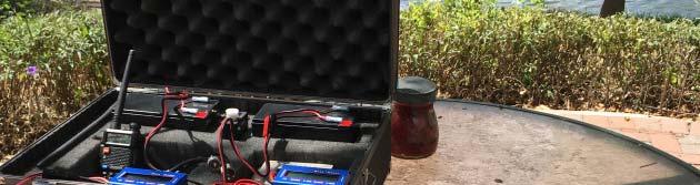
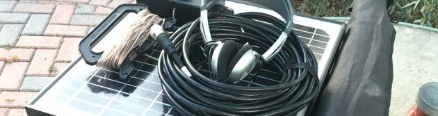
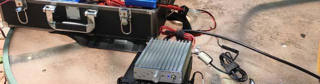
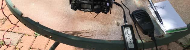
Solar Powered Portable Field Day Station. KG5EAO Rick Bono May 28, 2016
 Solar Powered Portable Field Day Station KG5EAO Rick Bono May 28, 2016 Field Day To work as many stations as possible on any and all amateur bands (excluding the 60, 30, 17, and 12-meter bands) and in
Chapter 6 Antenna Basics. Dipoles, Ground-planes, and Wires Directional Antennas Feed Lines
 Chapter 6 Antenna Basics Dipoles, Ground-planes, and Wires Directional Antennas Feed Lines Some General Rules Bigger is better. (Most of the time) Higher is better. (Most of the time) Lower SWR is better.
1997 MFJ ENTERPRISES, INC.
 INSTRUCTION MANUAL CAUTION: Read All Instructions Before Operating Equipment MFJ ENTERPRISES, INC. 300 Industrial Park Road Starkville, MS 39759 USA Tel: 601-323-5869 Fax: 601-323-6551 VERSION 6C COPYRIGHT
Beams and Directional Antennas
 Beams and Directional Antennas The Horizontal Dipole Our discussion in this chapter is about the more conventional horizontal dipole and the simplified theory behind dipole based designs. For clarity,
The first thing to realize is that there are two types of baluns: Current Baluns and Voltage Baluns.
 Choosing the Correct Balun By Tom, W8JI General Info on Baluns Balun is an acronym for BALanced to UNbalanced, which describes certain circuit behavior in a transmission line, source or load. Most communications
G3EJS 2-Tuner. Having recently bought an FT-817, and immediately missing the internal tuner my IC-703 has, I started looking for an answer.
 G3EJS 2-Tuner Having recently bought an FT-817, and immediately missing the internal tuner my IC-703 has, I started looking for an answer. There are tuners around, but everything I saw was just about as
QRP Presentation at HRU John Meade W2XS. Contact Info:
 QRP Presentation at HRU John Meade W2XS Contact Info: jm416@optonline.net John.meade@ncc.edu Topics QRP Presentation at HRU John Meade W2XS Philosophy of QRP Equipment Antennas My QRP Rig History in Pictures
ANTENNA THEORY WAVE PROPAGATION HF ANTENNAS
 ANTENNA THEORY WAVE PROPAGATION & HF ANTENNAS FREQUENCY SPECTRUM INFORMATION Frequency range American designator below 300 Hz..ELF (extremely Low Frequency) 300-3000 Hz..ILF (Intermediate Low Frequency)
What is a BALUN or UNUN:
 What is a BALUN or UNUN: A device to connect different types of antennas to various feed lines. Can transform impedances, choke common mode or change balanced to unbalanced BALUN Balanced to Unbalanced
MFJ-969 Versa Tuner II Instruction Manual
 MFJ-969 Versa Tuner II Instruction Manual General Information The MFJ-969 is a 300 watt RF output power antenna tuner that will match any transmitter or transceiver to virtually any antenna. Peak or average
SOME USES FOR RF1,RF5 and VA1 ANALYSTS. SWR Measurement
 SOME USES FOR RF1,RF5 and VA1 ANALYSTS THE HANDIEST INSTRUMENTS IN DECADES! When you put up an antenna in the the old days, it could be a real struggle. The only way to tell if it was tuned to the right
How to use your antenna tuner.
 How to use your antenna tuner. There's more to it than what is in your manual or on most how to do it websites! http://www.arrl.org/tis/info/ant-tuner-op.html Here is a neat site with a "T" network simulator.
4/25/2012. Supplement T9. 2 Exam Questions, 2 Groups. Amateur Radio Technician Class T9A: T9A: T9A: T9A:
 Amateur Radio Technician Class Element 2 Course Presentation ti ELEMENT 2 SUB-ELEMENTS Technician Licensing Class Supplement T9 Antennas, Feedlines 2 Exam Questions, 2 Groups T1 - FCC Rules, descriptions
4/29/2012. General Class Element 3 Course Presentation. Ant Antennas as. Subelement G9. 4 Exam Questions, 4 Groups
 General Class Element 3 Course Presentation ti ELEMENT 3 SUB ELEMENTS General Licensing Class Subelement G9 Antennas and Feedlines 4 Exam Questions, 4 Groups G1 Commission s Rules G2 Operating Procedures
Miniature Magnetic Loops By David Posthuma, WD8PUO
 Miniature Magnetic Loops By David Posthuma, WD8PUO Application Notes and Articles A General Overview After several years of curiosity and several months of research, I recently built two magnetic loops.
Copyright 2012, R. Eckweiler & OCARC, Inc. Page 1 of 5
 Heathkit of the Month #42: by Bob Eckweiler, AF6C Heathkit HD-1422-A Antenna Noise Bridge Introduction: If you work with antennas, an antenna noise bridge can be a very handy tool. Table 1 lists some of
ANTENNA BASICS FOR BEGINNERS
 ANTENNA BASICS FOR BEGINNERS PART 2 -DIPOLES DIPOLES -General MULTIBAND DIPOLES RF CHOKES 1 DIPOLES Several different variations of the dipole are also used, such as the folded dipole, short dipole, cage
VE7CNF - 630m Antenna Matching Measurements Using an Oscilloscope
 VE7CNF - 630m Antenna Matching Measurements Using an Oscilloscope Toby Haynes October, 2016 1 Contents VE7CNF - 630m Antenna Matching Measurements Using an Oscilloscope... 1 Introduction... 1 References...
END FED 6 40 Meter Multiband HF Antenna
 END FED 6 40 Meter Multiband HF Antenna Introduction This project produces an inexpensive, multiband, end fed HF antenna matchbox that is quick and easy to setup and use. The end fed feature adds convenience,
The Balun and The UNUN - page 1
 The Balun and The UNUN - page 1 When is a Balun, not a balun, when it is an UNUN! Balun = "BALanced-to-UNbalanced" Unun = "UNbalanced-to-UNbalanced" Looking at the two diagrams above you will see the common
One I had narrowed the options down, I installed some wire and started testing.
 Loft & Attic antennas for restricted spaces - M. Ehrenfried G8JNJ I ve recently been looking at designs for an efficient antenna that would fit in a loft. I hoped to find something that would work on with
Build a 12/17 Meter Trap Dipole Phil Salas AD5X
 Build a 12/17 Meter Trap Dipole Phil Salas AD5X Introduction Why a 12/17 meter rotatable dipole? Well, many folks have verticals for the lower bands, and multi-band dipoles or beams for 20-, 15-, and 10
Technician License. Course
 Technician License Course Technician License Course Chapter 4 Lesson Plan Module - 9 Antenna Fundamentals Feed Lines & SWR The Antenna System The Antenna System Antenna: Transforms current into radio waves
SWR myths and mysteries.
 SWR myths and mysteries. By Andrew Barron ZL3DW September 2012 This article will explain some of the often misunderstood facts about antenna SWR at HF and uncover some popular misconceptions. The questions
TBARC Programs Antenna Modeling with 4NEC2. By Randy Rogers AD7ZU 2010
 TBARC Programs Antenna Modeling with 4NEC2 By Randy Rogers AD7ZU 2010 Getting Started 4NEC2 is a completely free windows based tool suite to aid in the design and optimization of antenna systems 4NEC2
Pacific Antenna 20 and 40M Lightweight Dipole Kit
 Pacific Antenna 20 and 40M Lightweight Dipole Kit Antenna diagram showing configuration and lengths when assembled 7 8 16 9 16 9 Description The Pacific Antenna lightweight dual band dipole kit provides
Magnetic Loop Antenna - Multiband
 Magnetic Loop Antenna - Multiband Instruction Manual Thank you for purchasing this new product small Magnetic Loop Antenna Multiband. Manual contains important information. Please read all instructions
MFJ-834 RF Ammeter. Introduction. Uses
 MFJ-834 RF Ammeter Introduction Congratulations on purchasing the MFJ-834 RF Ammeter. The MFJ-834 is designed for measuring in-line RF feedline current on 1.8-30 MHz while having low interaction on the
Bob Brehm, AK6R Chief Engineer Palomar-Engineers.com. PVARC April Copyright 2016 Palomar Engineers, Inc.
 Bob Brehm, AK6R Chief Engineer Palomar-Engineers.com PVARC April 2016 Copyright 2016 Palomar Engineers, Inc. Causing Neighborhood RFI? IT S ALL YOUR FAULT WITH THAT BIG ANTENNA! Receiving RFI from Neighborhood?
Hamelectronicsmagazine.com / earlandrews.com **** mirror sites **** since FREE ON-LINE MAGAZINE and mail order parts as well!
 LNR PRECISION ---> QUAD BAND END FED HALF WAVE WIRE ANTENNA. -- VE3AB Earl Andrews - NEW REVISED ARTICLE: (OCT 2-2014). I previously had two wires attached to the matchbox in effort to try and get multiband
Ten-Tec Orion Sub Receiver VHF Filter Modification Prepared by Rick Williams, VE7TK
 Ten-Tec Orion Sub Receiver VHF Filter Modification Prepared by Rick Williams, VE7TK (Note: Those undertaking this modification do so at their own risk. The procedures outline a method of installing an
General License Class Chapter 6 - Antennas. Bob KA9BHD Eric K9VIC
 General License Class Chapter 6 - Antennas Bob KA9BHD Eric K9VIC Learning Objectives Teach you enough to get all the antenna questions right during the VE Session Learn a few things from you about antennas
What causes the Out-of-Balance Current in the coax and why does it Radiate?
 The EH Antenna - Out of Balance Current or Longitudinal Mode Current in the Coaxial Cable causes radiation from the coax. But how large a proportion of the total power is radiated or lost from this Current?
COAXIAL TRANSMISSION LINE COMMON-MODE CURRENT
 COAXIAL TRANSMISSION LINE COMMON-MODE CURRENT Introduction Coaxial transmission lines are popular for their wide frequency bandwidth and high resistance to electromagnetic interference (EMI). Coax cables
JC-5 4KW PEP, 1KW RMS AUTO ANTENNA COUPLER
 JC-5 4KW PEP, 1KW RMS AUTO ANTENNA COUPLER 1) DIRECTLY CONTROLLED BY ICOM, ALINCO & KENWOOD. 2) INDEPENDENT CAPACITOR INPUT AND OUTPUT BLOCKS! 3) 3 mm COIL WIRE & INTERNAL FAN FOR THE BIG COILS! 4) DIPPED
G7FEK LIMITED SPACE ANTENNA
 80, 40, 30, 17, 15, 12 m see tet for 20 & 10m operation For 20m operation add red wire 16.5ft ( 5.1m) 24 ft (7.4m) Copyright 2009 G7FEK During the 1980s Mike, G7FEK, described a limited space antenna suitable
Design of a Two-band Loaded Dipole Antenna
 David Birnbaum, KLYV 855 Acorn Ridge Ct., Tampa, FL 3365: dbirnbau@gmail.com Design of a Two-band Loaded Dipole Antenna Calculate the LC trap values given the physical size of the antenna and two desired
2005 MFJ ENTERPRISES, INC.
 Model MFJ-209 INSTRUCTION MANUAL CAUTION: Read All Instructions Before Operating Equipment MFJ ENTERPRISES, INC. 300 Industrial Park Road Starkville, MS 39759 USA Tel: 662-323-5869 Fax: 662-323-6551 VERSION
THE VK WINDOM. Seemed Like a Good Idea
 THE VK WINDOM Seemed Like a Good Idea Over the years there have been many articles about the Windom antenna. It was first popularized by a US amateur called Windom whose 40 m signal on this antenna was
Last year I described several Low Band RX antennas that would enable you to hear DX stations on 160, 80 and 40M. This will show you how to build
 Last year I described several Low Band RX antennas that would enable you to hear DX stations on 160, 80 and 40M. This will show you how to build transmit antennas that will help you break the pileups!
Technician Licensing Class. Antennas
 Technician Licensing Class Antennas Antennas A simple dipole mounted so the conductor is parallel to the Earth's surface is a horizontally polarized antenna. T9A3 Polarization is referenced to the Earth
G3EJS 2-Tuner. Having recently bought an FT-817, and immediately missing the internal tuner my IC-703 has, I started looking for an answer.
 G3EJS 2-Tuner Having recently bought an FT-817, and immediately missing the internal tuner my IC-703 has, I started looking for an answer. There are tuners around, but everything I saw was just about as
Made in Russia. By Serge V. Satyr, RW3XA (ex: UA3XBY), Obninsk, Russia Credit Line:
, Obninsk, Russia Credit Line:") By Serge V. Satyr, RW3XA (ex: UA3XBY), Obninsk, Russia rw3xa@qsl.net Translated by RW3XW Credit Line: http://www.feerc.obninsk.org/rw3xa/ant/gpxa_en.htm Made in Russia As a rule, we need taking some steps
By Serge V. Satyr, RW3XA (ex: UA3XBY), Obninsk, Russia rw3xa@qsl.net Translated by RW3XW Credit Line: http://www.feerc.obninsk.org/rw3xa/ant/gpxa_en.htm Made in Russia As a rule, we need taking some steps
MFJ-835 RF Ammeter. Introduction. Uses
 MFJ-835 RF Ammeter Introduction Congratulations on purchasing the MFJ-835 Balanced Line RF Ammeter. The MFJ-835 is designed for measuring balanced RF feedline current on 1.8-30 MHz while having low interaction
Milton Keynes Amateur Radio Society (MKARS)
") Milton Keynes Amateur Radio Society (MKARS) Intermediate Licence Course Feeders Antennas Matching (Worksheets 31, 32 & 33) MKARS Intermediate Licence Course - Worksheet 31 32 33 Antennas Feeders Matching
Milton Keynes Amateur Radio Society (MKARS) Intermediate Licence Course Feeders Antennas Matching (Worksheets 31, 32 & 33) MKARS Intermediate Licence Course - Worksheet 31 32 33 Antennas Feeders Matching
Emergency Antennas. Presented by Ham Hilliard W4GMM
 Emergency Antennas Presented by Ham Hilliard W4GMM Dipole antenna Vertical antenna Random wire antenna Dipole antenna The half wave dipole antenna consists of a conductive wire or rod that is half the
J-Poles. Mythbusting J-Pole Antennas
 Mythbusting J-Pole Antennas For an antenna to work correctly, it must do two things well 1) Accept power from the feed line impedance match, SWR (ideally) 1:1 2) Radiate power in a pattern that is useful
How to Blow Up Your Balun
 How to Blow Up Your Balun (and other things too ) By Dean Straw, N6BV Sea-Pac June 7, 2014 Photos courtesy Jim Brown, K9YC 1 This is What I Intend to do Today I will examine stresses placed on common-mode
MFJ-941E Versa Tuner II GENERAL INFORMATION:
 GENERAL INFORMATION: MFJ VERSA TUNER II The MFJ-941E is designed to match virtually any transmitter to any antenna, including dipoles, inverted-vees, verticals, mobile whips, beams, random wires, and others
General Licensing Class Circuits
 General Licensing Class Circuits Valid July 1, 2011 Through June 30, 2015 1 Amateur Radio General Class Element 3 Course Presentation ELEMENT 3 SUB-ELEMENTS (Groupings) Your Passing CSCE Your New General
A Tri Band Antenna for 2 meters, 220 MHz, and 70cm Antenna Without Radials. By: Edison Fong (WB6IQN)
") A Tri Band Antenna for 2 meters, 220 MHz, and 70cm Antenna Without Radials By: Edison Fong (WB6IQN) Twenty years ago a single band handie talkie would have been adequate for emergency use since almost
A Tri Band Antenna for 2 meters, 220 MHz, and 70cm Antenna Without Radials By: Edison Fong (WB6IQN) Twenty years ago a single band handie talkie would have been adequate for emergency use since almost
MFJ ENTERPRISES, INC.
 Model MFJ-962D Requires 9VDC Battery or 12VDC Source for Meter Operation INSTRUCTION MANUAL CAUTION: Read All Instructions Before Operating Equipment MFJ ENTERPRISES, INC. 300 Industrial Park Road Starkville,
About Q. About Q, Xtal Set Society, Inc
 About Q, Xtal Set Society, Inc In the crystal radio hobby and in electronics in general Q can refer to a number of things: the Q of a coil, the Q of a circuit, the quality factor of some item, or the label
The Balun and The UnUn - page 1
 The Balun and The UnUn - page 1 When is a Balun, not a Balun, when it is an UnUn! Balun = "Balanced-to-Unbalanced" UnUn = "Unbalanced-to-Unbalanced" Looking at the two diagrams above you will see the common
AA-35 ZOOM. RigExpert. User s manual. Antenna and cable analyzer
 AA-35 ZOOM Antenna and cable analyzer RigExpert User s manual . Table of contents Introduction Operating the AA-35 ZOOM First time use Main menu Multifunctional keys Connecting to your antenna SWR chart
Chokes and Isolation Transformers For Receiving Antennas By Jim Brown K9YC 2018 by James W. Brown All rights reserved
 Chokes and Isolation Transformers For Receiving Antennas By Jim Brown K9YC 2018 by James W. Brown All rights reserved Why We Need Them A feedline must be grounded where it enters the shack-for lightning
Pacific Antenna 20 and 40M Lightweight Dipole Kit
 Pacific Antenna 20 and 40M Lightweight Dipole Kit Diagram showing configuration and approximate lengths 8 3 16 9 16 9 8 3 Description The Pacific Antenna lightweight dual band, trap dipole kit provides