Antenna Design for FM-02
|
|
|
- Hope Singleton
- 6 years ago
- Views:
Transcription
1 Antenna Design for FM-02 I recently received my FM-02 FM transmitter which I purchased from WLC. I researched the forum on what antennas where being used by the DIY community and found a nice write-up on building a dipole. I also found many people were having issues with their antenna transmitting to the road in front of their house when using this dipole. I offer this white paper as some technical information on antenna design and where this information might explain and help those with issues resolve their problems. At the end of the paper, I will present a ¼ wave vertical antenna I built which alleviates many of the issues that can be associated with a dipole antenna. I will support my statements by referencing information published by ARRL (American Radio Relay League) and several Ham sites on the Internet. As a note up front when you start researching information about your FM Broadcast Band antenna you will find a ton of Ham information on the topics you are looking for. Be for-warned, most all of the Ham information is based on transmitting in the HF (High Frequency) spectrum 10 meters being the top of the band around 30 mhz. Our FM system is part of the VHF (Very High Frequency) spectrum where small issues in the HF band can become very big in the VHF realm. The FM-02 is rated as transmitting 30mw (that s milliwatts watts) into a 50 ohm load. Compare that to a CB radio rated at 4.0 watts AM. Transmitters are designed to be paired with a coax transmission line whose line impedance is expected to match its load. The FM-02 was designed for 50 ohms so this means we should use a 50 ohm coax. I purchased some 25ft of RG8 already terminated with BCN connectors from Amazon for under $10. At the end of this paper, I will present a list of various cables and the important characteristic associated with each. Most on the forum have elected to use a dipole. The following shows the radiation pattern associated from a dipole (taken from AARL Handbook page 21.6)

2 The important point to this illustration is that the energy is radiated perpendicular to the axis of the dipole. If you use a dipole antenna and orient it horizontally and one of the ends points towards the street you have the antenna positioned incorrectly the smallest amount of energy is being transmitted towards the street you need to place it on a wall that is parallel to the street. What is the feed-point impedance of your dipole antenna? The following graph (ARRL page 21.3) shows radiation resistance for a dipole mounted both in a horizontal and vertical position. Notice how the horizontally positioned dipole s resistance changes with respect to height above ground. The dipole mounted vertically sees much less variation as long as it s positioned greater than.3 wave lengths above the ground (at least 3 to 5 feet).

3 Those of you using your dipole antenna, and it s positioned horizontally, should make sure it is at least 12 feet above ground. If the antenna is any closer to ground, the characteristic impedance of 70 ohms will not hold true; (as you can see it will be about 45 ohms is 1 foot off the ground, 98 ohms if 4 feet off the ground, 58 ohms if 6 feet off the ground, and 84 ohms if 9 feet off the ground). In summary, If you are using a dipole antenna you should position it vertically at least 5 feet above the ground or horizontally at least 12 feet above the ground. Let s assume the dipole is position so that the characteristic impedance of 70 ohms is presented to the RG8 coax cable. Since the antenna s 70 ohm impedance does not match the 50 ohms being presented by the coax we have an impedance mismatch which will result in some of the power being reflected back down the coax creating standing waves. You would have a SWR (Standing Wave Ratio) of 1.4 to 1. Note this is an acceptable SWR. SWR meters are usually used to measure this mismatch. Note there are very few SWR meters that can be used in the system we are creating (those that can are expensive or custom made). The SWR meters normally available and within the DIY budget are designed for the CB community. They are designed to measure transmitters greater than 1 watt remember we are.03 watts max. These meters are just not sensitive enough to be useful. Your dipole antenna is created by cutting two lengths of wire and connecting them to the coax cable. How long of a wire do you cut? In free space (vacuum), wave length ( in feet) is equal to / frequency (in mhz).
4 The wave length is smaller (only 95% of free space) when the rf wave runs through copper speed is slower (AARL Handbook page 19.1) If you elect to use wire that is enclosed with insulation (not bare copper) it is slowed another 3 to 5% because of the capacitance associate with the insulation (AARL Handbook page 21.8) As an example let s say we want to transmit on mhz how long of wire do I cut if I m uses bare wire and how long if I m using insulated wire? Bare wire: Each segment is ¼ wave length in size so L = (983.6 *.95) / (100.1 * 4) = ft or 28.0 inches. The.95 is due to the RF being conducted down copper and the divide by 4 is because we want ¼ of a wave length. Insulated copper wire: L (@ 3%) = 28.0 *.97 = 27.2 inches L (@ 5%) = 28.0 *.95 = 26.6 inches So if we are using bare wire cut it to 28 inches if using insulated wire cut it at 27 inches. This is the point where most of the forum information stops ---- but there is a very critical aspect of our dipole design that has not been addressed. The dipole antenna is a balanced load where equal, but opposite, currents are traveling down each segment of the antenna. Coax is not balanced hence it is unbalanced. DC current run through the complete cross section of the wire. When we are dealing with AC current, it no longer runs through the complete cross section it migrates (based on frequency) so it is only being conducted on the out rim of the copper wire. This is known as skin effect. At 100 mhz, most of the current is being conducted very close to the surface of the copper conductor. The following diagram illustrates current flow associated with a coax joined to a dipole antenna (AARL Handbook page 21.6)
5 Remember skin effect. Current I2 is flowing on the inside surface of the coax braid and current I3 is flowing of the outside surface of the coax braid. Current flowing on the outer surface of the coax is called Common Mode current.
6 The impedance seen by the common mode current is called common mode impedance. The common mode impedance is directly related to the length of wire from dipole segment connection all the way to rf ground --- this means the length of your coax, plus the length of wire associated with your transmitter and power supply, and also length of wire in your house to get to the rf ground. (ARRL Antenna Book page 26.17) Common mode currents cause your antenna s radiation pattern to distort because your coax and house wire now also become part of the radiator. Worst case occurs when the length associated with this common mode current is a multiple of ½ wave length. This causes the common mode impedance it appear as a short and I3 (common mode current) to be at its maximum. This is not wanted and needs to be addressed. I believe this is one of the main reasons some people are having transmission issues. This common mode current can wipe out the output stage in your FM transmitter and dramatically reduce transmitter power. On the other side of the coin, as the rf length approaches multiples of ¼ wave length the common mode impedance is very large and I3 is minimal. That is why it just hooking the coax directly to the dipole works for some and won t for others. Note we are talking about a wire length (includes house wiring) difference being a multiple of 2 to 3 feet in length --- making your dipole s perform go from from OK to Terrible. (ARRL Antenna Book page 26.17) Consider this worst case scenario Can t transmit to the street because we have our dipole position horizontally, directly fed by coax (with none of the solutions below in place), the segment closest to the street is the segment conducting common mode currents and the rf cable length is a multiple of ½ wave length (shorted segment)! So how do we stop I3 (common mode current) from occurring. Three (3) ways:

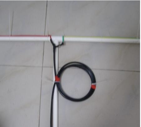
7 Solution #1. The easiest way is to place an rf choke in the path of I3. Hams have been doing this for years. Simply make a coil from your coax feed line near the dipole. The coax braid is then the conductor which forms an inductor hence a choke. You will see this coil referred to as a choke balun or ugly balun. I have stayed from calling it a balun because it is not. The key is to create a coil of X inches in diameter and Y number of turns. X and Y are unknown. There are tools that can show the frequency of resonance for your coil but very few of us will have access to those tools. You must do this by trial and error. Try different sizes and turns until you find one that improves your situation. The only problem with this solution is not knowing at what frequency the coil resonates at (fo). The impedance for frequencies less than fo are inductive (which we want) and the impedance for frequencies above fo are capacitive (don t want). So as a guide line in your trail and error process keep coil diameter as large as possible (not over 4 inches) and keep the number of turns to a minimum not over 6. The following site discusses this type of rf choke:
8


9 Solution #2: We can also create a choke by adding ferrite material to the coax. Taken from site: Please note one of these is not enough. A typical application requires from 8 to 24 of these devices.
10 Solution #3: Use a balun. Balun is an acronym for Balance to Unbalanced transformation. A balun is used to transform the system from unbalanced feed to a balanced feed and transform impedance at the same time (if required) Most of you will recognize the TV balun used on old televisions 300 ohm twin lead to coax. This device also performed a 4 to 1 impedance transformation 300 ohms to 75. Coax can be used to manipulate impedances at specific frequencies. Do a google for Stub Tuning if you are interested or pick up the ARRL Handbook. The following balun can be found at This is the only method where you design the system so you don t have to take other measures to block common mode current because they are NOT present. Your unbalanced coax is transformed into a balanced line by placing the two segments, of proper length, in parallel. The two additional lengths of coax are added to you feed and placed within your PVC pipe.
) = 983.6 / frequency (in mhz).")
11 If you choose to build the above balun how long are the lengths of coax required? Let s go back to our example of transmitting on mhz. I stated earlier that L (wave length in ft In free space (vacuum )) = / frequency (in mhz). I also stated that current runs on the surface of the copper conductor and it is slowed by the capacitance associated with the material directly in contact with the copper conductor. There is a term called Velocity Factor that defines the amount the rf wave is slowed by when not conducting in free space. From ARRL Antenna Book page 24.4 the following equation for the length of coax associated with a ¼ wave: The following table is from ARRL Antenna Book page 24.18: VF is the Velocity Factor. RG-8 is the BIG ½ inch cable used by most Hams. RG-8X is what I purchased with BCN connectors already attached. If you look at the table this coax is only ¼ inches in diameter. This was commonly used for Ethernet wiring before CAT5 cable became popular. So --- the ¼ wave length segment is (245.9 *.86) / = 2.11 ft or inches. The ¾ wave length segment = 3 * = 76 inches or 6.3 ft.
 mounted vertically on top of a ground plane.")
12 Quarter wave Vertical antenna: I present the following antenna to the DIY community to be used with your FM transmitter instead of the classic dipole antenna. The active element is ¼ wave length (1/2 of your dipole) mounted vertically on top of a ground plane. The feed-point impedance is 50 ohms and unbalanced so we can directly connect our coax line without fear of common mode currents and the issues associated with them. I use a modified ground plane I only use two (2) ¼ wave radials. Many of the build techniques used in the dipole antenna are used here so I will not repeat them. I purchased ¼ inch eye bolts at HD. I had to use 1 inch PVC so that the eye bolts would fit inside the PVC pipe. The dipole constructions calls for the use of a T. I use a CROSS connection instead.

13 The dipole construction suggests connecting the antenna elements (wire) to the coax by using a piece of perf board. I directly soldered the coax to the ¼ wave length pieces of wire as shown below. I used insulated 12 ga wire I had left over from wiring my garage so I used that as the antenna elements. I used the 4% length adjustment because of the capacitance associated with the insulation. The two ground radials are really a single length of wire ½ wave length in length (after I created loops in the ends per the dipole construction technique. Simply remove a 1/2 inch of insulation in the middle of the ½ wave length piece of wire and directly solder the coax braid to it. I left about a ½ inch of free braid from the coax to the solder connection so that heat (during soldering) would not melt the coax insulation (see picture below). I cut the 12 gage wire used for the active antenna element 1 inch less than calculated because of the exposed inch of coax inner conductor. I used the eye bolts to apply tension to the antenna elements thereby achieving the correct length without kinks or bends.

14 This is the finished antenna. I plan on installing a short length of PVC pipe out the bottom to serve as a strain relief for the coax. The BCN connector is also shown.

15 When I purchased the FM-02 from WLC, I also purchased the dummy antenna used for testing. Max length on the vertical element is 12 inches.
16 Antenna performance: I am powering my FM-02 from a well regulated 13.4v power supply capable of delivering 3.5 amps. I originally tested the transmitter using the dummy antenna positioned on my desk. Audio was provided via an IPOD. Transmitting frequency was mhz. My office is located on the second floor so I m not at ground level. The dummy antenna provided excellent audio to a range of about 500 yards. My truck radio was used as the receiver. Reception was not line of site as multiple houses and trees were in the transmission path. At 500 yards, I started losing the hi frequencies in the audio the s sounds in speech became very poor. I replaced the dummy antenna with the ¼ wave vertical antenna presented in this paper. The antenna was placed on a bed positioned vertically (in reality I will hang it on a wall). I was able to drive more than twice as far before I noticed the s distortion. The antenna is simple to build and does not have the common mode current concerns associated when driving a dipole antenna. Enjoy. Joe Hinkle
Cray Valley Radio Society. Real Life Wire Antennas
 Cray Valley Radio Society Real Life Wire Antennas 1 The basic dipole The size of an antenna is determined by the wavelength of operation In free space: ~3x10 8 m/s Frequency x Wavelength = Speed of Light,
A short, off-center fed dipole for 40 m and 20 m by Daniel Marks, KW4TI
 A short, off-center fed dipole for 40 m and 20 m by Daniel Marks, KW4TI Version 2017-Nov-7 Abstract: This antenna is a 20 to 25 foot long (6.0 m to 7.6 m) off-center fed dipole antenna for the 20 m and
COAXIAL TRANSMISSION LINE COMMON-MODE CURRENT
 COAXIAL TRANSMISSION LINE COMMON-MODE CURRENT Introduction Coaxial transmission lines are popular for their wide frequency bandwidth and high resistance to electromagnetic interference (EMI). Coax cables
Page 1The VersaTee Vertical 60m, 80m Modular Antenna System Tutorial Manual
 Page 1The VersaTee Vertical 60m, 80m Modular Antenna System Tutorial Manual by: Lou Rummel, KE4UYP Page 1 In the world of low band antennas this antenna design is unique in many different ways. 1. It is
Intermediate Course (5) Antennas and Feeders
 Antennas and Feeders") Intermediate Course (5) Antennas and Feeders 1 System Transmitter 50 Ohms Output Standing Wave Ratio Meter Antenna Matching Unit Feeder Antenna Receiver 2 Feeders Feeder types: Coaxial, Twin Conductors
Intermediate Course (5) Antennas and Feeders 1 System Transmitter 50 Ohms Output Standing Wave Ratio Meter Antenna Matching Unit Feeder Antenna Receiver 2 Feeders Feeder types: Coaxial, Twin Conductors
Milton Keynes Amateur Radio Society (MKARS)
") Milton Keynes Amateur Radio Society (MKARS) Intermediate Licence Course Feeders Antennas Matching (Worksheets 31, 32 & 33) MKARS Intermediate Licence Course - Worksheet 31 32 33 Antennas Feeders Matching
Milton Keynes Amateur Radio Society (MKARS) Intermediate Licence Course Feeders Antennas Matching (Worksheets 31, 32 & 33) MKARS Intermediate Licence Course - Worksheet 31 32 33 Antennas Feeders Matching
Amateur Extra Manual Chapter 9.4 Transmission Lines
 9.4 TRANSMISSION LINES (page 9-31) WAVELENGTH IN A FEED LINE (page 9-31) VELOCITY OF PROPAGATION (page 9-32) Speed of Wave in a Transmission Line VF = Velocity Factor = Speed of Light in a Vacuum Question
MFJ-219/219N 440 MHz UHF SWR Analyzer TABLE OF CONTENTS
 MFJ-219/219N 440 MHz UHF SWR Analyzer TABLE OF CONTENTS Introduction...2 Powering The MFJ-219/219N...3 Battery Installation...3 Operation Of The MFJ-219/219N...4 SWR and the MFJ-219/219N...4 Measuring
1) Transmission Line Transformer a. First appeared on the scene in 1944 in a paper by George Guanella as a transmission line transformer, the 1:1
 Transmission Line Transformer a. First appeared on the scene in 1944 in a paper by George Guanella as a transmission line transformer, the 1:1") 1) Transmission Line Transformer a. First appeared on the scene in 1944 in a paper by George Guanella as a transmission line transformer, the 1:1 Guanella Balun is the basic building Balun building block.
1) Transmission Line Transformer a. First appeared on the scene in 1944 in a paper by George Guanella as a transmission line transformer, the 1:1 Guanella Balun is the basic building Balun building block.
Chapter 6 Antenna Basics. Dipoles, Ground-planes, and Wires Directional Antennas Feed Lines
 Chapter 6 Antenna Basics Dipoles, Ground-planes, and Wires Directional Antennas Feed Lines Some General Rules Bigger is better. (Most of the time) Higher is better. (Most of the time) Lower SWR is better.
Technician Licensing Class. Antennas
 Technician Licensing Class Antennas Antennas A simple dipole mounted so the conductor is parallel to the Earth's surface is a horizontally polarized antenna. T9A3 Polarization is referenced to the Earth
WHY YOU NEED A CURRENT BALUN
 HF OPERATORS WHY YOU NEED A CURRENT BALUN by John White VA7JW NSARC HF Operators 1 What is a Balun? A BALUN is a device typically inserted at the feed point of a dipole-like antenna wire dipoles, Yagi
Least understood topics by most HAMs RF Safety Ground Antennas Matching & Feed Lines
 Least understood topics by most HAMs RF Safety Ground Antennas Matching & Feed Lines Remember this question from the General License Exam? G0A03 (D) How can you determine that your station complies with
Basic Wire Antennas. Part II: Loops and Verticals
 Basic Wire Antennas Part II: Loops and Verticals A loop antenna is composed of a single loop of wire, greater than a half wavelength long. The loop does not have to be any particular shape. RF power can
Feed Line Currents for Neophytes.
 Feed Line Currents for Neophytes. This paper discusses the sources of feed line currents and the methods used to control them. During the course of this paper two sources of feed line currents are discussed:
The J-Pole Antenna. Gary Wescom
 The J-Pole Antenna Gary Wescom - 2018 Much has been written about the J-Pole antenna. A simple Google search will net days worth of reading material on the subject. That would tend to indicate this paper
TWO METER HOMEMADE SLIM JIM ANTENNA
 Gordon Gibby July 15, 2016 TWO METER HOMEMADE SLIM JIM ANTENNA WIRE: Start with a piece of solid #14 AWG household wire approximately 3 yards and 9 inches long (117 ) (It is easier to be a couple inches
Technician Licensing Class T9
 Technician Licensing Class T9 Amateur Radio Course Monroe EMS Building Monroe, Utah January 11/18, 2014 January 22, 2014 Testing Session Valid dates: July 1, 2010 June 30, 2014 Amateur Radio Technician
Antennas and Propagation Chapters T4, G7, G8 Antenna Fundamentals, More Antenna Types, Feed lines and Measurements, Propagation
 Antennas and Propagation Chapters T4, G7, G8 Antenna Fundamentals, More Antenna Types, Feed lines and Measurements, Propagation =============================================================== Antenna Fundamentals
MFJ-249B HF/VHF SWR ANALYZER
 TABLE OF CONTENTS MFJ-249B... 2 Introduction... 2 Powering The MFJ-249B... 3 Battery Installation... 3 Alkaline Batteries... 3 NiCd Batteries... 4 Power Saving Mode... 4 Operation Of The MFJ-249B...5 SWR
4 Antennas as an essential part of any radio station
 4 Antennas as an essential part of any radio station 4.1 Choosing an antenna Communicators quickly learn two antenna truths: Any antenna is better than no antenna. Time, effort and money invested in the
How to use your antenna tuner.
 How to use your antenna tuner. There's more to it than what is in your manual or on most how to do it websites! http://www.arrl.org/tis/info/ant-tuner-op.html Here is a neat site with a "T" network simulator.
SWR myths and mysteries.
 SWR myths and mysteries. By Andrew Barron ZL3DW September 2012 This article will explain some of the often misunderstood facts about antenna SWR at HF and uncover some popular misconceptions. The questions
4/29/2012. General Class Element 3 Course Presentation. Ant Antennas as. Subelement G9. 4 Exam Questions, 4 Groups
 General Class Element 3 Course Presentation ti ELEMENT 3 SUB ELEMENTS General Licensing Class Subelement G9 Antennas and Feedlines 4 Exam Questions, 4 Groups G1 Commission s Rules G2 Operating Procedures
Optimizing Your Stations Performance
 Optimizing Your Stations Performance A few hints / techniques, recommendations for getting the most RF out to the Antenna from your HF, VHF / UHF station. Tonights Presenters: Doug Theriault NO1D John
WCARES NEEDS YOU! CONSIDER MAKING A TECHNICAL PRESENTATION AT AN UPCOMING CHEW & CHAT MEETING LEARN SOMETHING NEW AND PRESENT
 WCARES NEEDS YOU! CONSIDER MAKING A TECHNICAL PRESENTATION AT AN UPCOMING CHEW & CHAT MEETING SHARE WHAT YOU KNOW LEARN SOMETHING NEW AND PRESENT IT CONTACT TIM AD4CJ AD4CJ@arrl.net 1 Transmission Line
Technician License Course Chapter 4. Lesson Plan Module 9 Antenna Fundamentals, Feed Lines & SWR
 Technician License Course Chapter 4 Lesson Plan Module 9 Antenna Fundamentals, Feed Lines & SWR The Antenna System Antenna: Transforms current into radio waves (transmit) and vice versa (receive). Feed
The Fabulous Dipole. Ham Radio s Most Versatile Antenna
 The Fabulous Dipole Ham Radio s Most Versatile Antenna 1 What is a Dipole? Gets its name from its two halves One leg on each side of center Each leg is the same length It s a balanced antenna The voltages
Table of Contents. MFJ-1778 G5RV Multiband Antenna
 Table of Contents MFJ-1778 G5RV Multiband Antenna Introduction... 1 Theory Of Operation... 1 80 meter band:... 1 40 meter band:... 1 30 meter band:... 2 20 meter band:... 2 17 meter band:... 2 15 meter
CHAPTER 8 ANTENNAS 1
 CHAPTER 8 ANTENNAS 1 2 Antennas A good antenna works A bad antenna is a waste of time & money Antenna systems can be very inexpensive and simple They can also be very expensive 3 Antenna Considerations
4/25/2012. Supplement T9. 2 Exam Questions, 2 Groups. Amateur Radio Technician Class T9A: T9A: T9A: T9A:
 Amateur Radio Technician Class Element 2 Course Presentation ti ELEMENT 2 SUB-ELEMENTS Technician Licensing Class Supplement T9 Antennas, Feedlines 2 Exam Questions, 2 Groups T1 - FCC Rules, descriptions
RX Directional Antennas. Detuning of TX Antennas.
 1. Models Impact of Resonant TX antennas on the Radiation Pattern of RX Directional Antennas. Detuning of TX Antennas. Chavdar Levkov, lz1aq@abv.bg, www.lz1aq.signacor.com 2-element small loops and 2-element
VHF/UHF Dual Band J-Pole. By: Ed Fong WB6IQN
 VHF/UHF Dual Band J-Pole By: Ed Fong WB6IQN email: edison_fong@hotmail.com ARRL VHF/UHF Antenna Classics ARRL Vol. 8 Antenna Compendium ARRL Vol. 3 Antenna Compendium QST March 2007 QST February 2003 QST
Technician License. Course
 Technician License Course Technician License Course Chapter 4 Lesson Plan Module - 9 Antenna Fundamentals Feed Lines & SWR The Antenna System The Antenna System Antenna: Transforms current into radio waves
Nick Garner N3WG and George Zafiropoulos KJ6VU
 Nick Garner N3WG and George Zafiropoulos KJ6VU Introduction Over the last few years, there has been a significant increase in the number of radio amateurs interested in portable operating. This is due
ARNSW Balun Day. Balun construction
 ARNSW Balun Day Balun construction Typical Baluns All built from locally available components. Balun uses Most baluns are used to match the 50Ω output of a transceiver to an antenna. A centre fed dipole
The DBJ-1: A VHF-UHF Dual-Band J-Pole
 By Edison Fong, WB6IQN The DBJ-1: A VHF-UHF Dual-Band J-Pole Searching for an inexpensive, high-performance dual-band base antenna for VHF and UHF? Build a simple antenna that uses a single feed line for
Coming next: Wireless antennas for beginners
 Coming next: Wireless antennas for beginners In other rooms: Logbook of the World (Sussex Suite) SO2R contest operation (Stable Suite) Wires for your wireless: Simple wire antennas for beginners dominic
Antennas and Stuff. John Kernkamp WB4YJT
 Antennas and Stuff John Kernkamp WB4YJT John Kraus W8JK June 28, 1910 - July 18, 2004 Invented the helical antenna, the corner reflector, and the W8JK End-Fire array. In 1950 designed and built the Big
MFJ Balanced Line Tuner
 MFJ Balanced Line Tuner Introduction The MFJ-974H balanced line antenna tuner is a fully balanced true balanced line antenna tuner, providing superb current balance throughout a very wide matching range
Introduction. Understanding Power Ratings. Peak Reading SWR/Wattmeter
 Introduction The MFJ-962D is a "T" network roller inductor tuner with built-in antenna switching, RF power and SWR metering and a 1:1 balun. The largest amplifiers that can safely be used include the Heathkit
Portable or Emergency VHF Antennas Paul R. Jorgenson KE7HR
 For emergency or public service events it is often necessary to have more antenna than the rubber duck on your handheld VHF radio. Nearly ANY external antenna will provide more coverage for your handheld
A TRANSMISSION LINE BALANCE TEST METER
 by Lloyd Butler VK5BR with modifications by Phil Storr VK5SRP. Here is a simple meter to check the balance of currents running in the two legs of a transmission line. It can be used to check the balance
J-Poles. Mythbusting J-Pole Antennas
 Mythbusting J-Pole Antennas For an antenna to work correctly, it must do two things well 1) Accept power from the feed line impedance match, SWR (ideally) 1:1 2) Radiate power in a pattern that is useful
Technician License. Course
 Technician License Course Technician License Course Chapter 4 Lesson Plan Module - 10 Practical Antennas The Dipole Most basic antenna The Dipole Most basic antenna The Dipole Total length is ½ wavelength
FCC Technician License Course
 FCC Technician License Course 2014-2018 FCC Element 2 Technician Class Question Pool Presented by: Tamiami Amateur Radio Club (TARC) WELCOME To the third of 4, 3-hour classes presented by TARC to prepare
Jacques Audet VE2AZX. Nov VE2AZX 1
 Jacques Audet VE2AZX VE2AZX@amsat.org Nov. 2006 VE2AZX 1 - REASONS FOR USING A BALUN - TYPES OF BALUNS - CHECK YOUR BALUN WITH AN SWR ANALYZER - MEASURING THE IMPEDANCE OF A NUMBER OF FERRITES - IMPEDANCE
The design of Ruthroff broadband voltage transformers M. Ehrenfried G8JNJ
 The design of Ruthroff broadband voltage transformers M. Ehrenfried G8JNJ Introduction I started investigating balun construction as a result of various observations I made whilst building HF antennas.
and Related Topics W7KVI, HARC Original: 3/26/16
 Baluns, Ununs, and Related Topics W7KVI, HARC Original: 3/26/16 This Presentation Informal & brisk - 52 slides (too many unless you re an enthusiast!) Discussion encouraged if not extensive, interrupt
General License Class Chapter 6 - Antennas. Bob KA9BHD Eric K9VIC
 General License Class Chapter 6 - Antennas Bob KA9BHD Eric K9VIC Learning Objectives Teach you enough to get all the antenna questions right during the VE Session Learn a few things from you about antennas
Emergency Antennas. Presented by Ham Hilliard W4GMM
 Emergency Antennas Presented by Ham Hilliard W4GMM Dipole antenna Vertical antenna Random wire antenna Dipole antenna The half wave dipole antenna consists of a conductive wire or rod that is half the
Technician Licensing Class. Lesson 4. presented by the Arlington Radio Public Service Club Arlington County, Virginia
 Technician Licensing Class Lesson 4 presented by the Arlington Radio Public Service Club Arlington County, Virginia 1 Quiz Sub elements T6 & T7 2 Good Engineering Practice Sub element T8 3 A Basic Station
Lesson 11: Antennas. Copyright Winters Version 1.0. Preparation for Amateur Radio Technician Class Exam
 Lesson 11: Antennas Preparation for Amateur Radio Technician Class Exam Topics Antenna ½ wave Dipole antenna ¼ wave Vertical antenna Antenna polarization Antenna location Beam antennas Test Equipment Exam
A HIGH PERFORMANCE AIRBAND ANTENNA FOR YOUR ULTRALIGHT / LIGHTSPORT AIRCRAFT by Dean A. Scott (revised March, 2018)
") A HIGH PERFORMANCE AIRBAND ANTENNA FOR YOUR ULTRALIGHT / LIGHTSPORT AIRCRAFT by Dean A. Scott (revised March, 2018) In this article I present a simple, easy to construct, and easy to mount Inverted V halfwave
A HIGH PERFORMANCE AIRBAND ANTENNA FOR YOUR ULTRALIGHT / LIGHTSPORT AIRCRAFT by Dean A. Scott (revised March, 2018) In this article I present a simple, easy to construct, and easy to mount Inverted V halfwave
1997 MFJ ENTERPRISES, INC.
 INSTRUCTION MANUAL CAUTION: Read All Instructions Before Operating Equipment MFJ ENTERPRISES, INC. 300 Industrial Park Road Starkville, MS 39759 USA Tel: 601-323-5869 Fax: 601-323-6551 VERSION 6C COPYRIGHT
MFJ-949E. tuner antenowy skrzynka antenowa. Instrukcja obsługi. importer:
 Instrukcja obsługi MFJ-949E tuner antenowy skrzynka antenowa importer: PRO-FIT Centrum Radiokomunikacji InRadio ul. Puszkina 80 92-516 Łódź tel: 42 649 28 28 e-mail: biuro@inradio.pl www.inradio.pl MFJ-949E
A HIGH PERFORMANCE AIRBAND ANTENNA FOR YOUR ULTRALIGHT / LIGHTSPORT AIRCRAFT by Dean A. Scott August 9, 2006 (revised January, 2011)
") A HIGH PERFORMANCE AIRBAND ANTENNA FOR YOUR ULTRALIGHT / LIGHTSPORT AIRCRAFT by Dean A. Scott August 9, 2006 (revised January, 2011) In this article I present a simple, easy to construct, and easy to mount
A HIGH PERFORMANCE AIRBAND ANTENNA FOR YOUR ULTRALIGHT / LIGHTSPORT AIRCRAFT by Dean A. Scott August 9, 2006 (revised January, 2011) In this article I present a simple, easy to construct, and easy to mount
Beams and Directional Antennas
 Beams and Directional Antennas The Horizontal Dipole Our discussion in this chapter is about the more conventional horizontal dipole and the simplified theory behind dipole based designs. For clarity,
AD5X. The 43-Foot Vertical. Phil Salas - AD5X Phil Salas AD5X. Richardson, Texas
 The 43-Foot Vertical Phil Salas - AD5X ad5x@arrl.net Outline Why a vertical? Ground Losses and Antenna Efficiency Why a 43-foot vertical? SWR-related coax and unun losses Matching Networks for 160- and
Wire Antennas For Limited Space
 Wire Antennas For Limited Space Jim Brown K9YC Santa Cruz, CA http://audiosystemsgroup.com Our Objectives Good Antennas Good efficiency Good predictable patterns Minimal noise pickup and RFI Inexpensive
How to Blow Up Your Balun
 How to Blow Up Your Balun (and other things too ) By Dean Straw, N6BV Sea-Pac June 7, 2014 Photos courtesy Jim Brown, K9YC 1 This is What I Intend to do Today I will examine stresses placed on common-mode
Users Manual. 200W HF/50MHz Band Auto Antenna Tuner. Model HC-200AT
 Users Manual 200W HF/50MHz Band Auto Antenna Tuner Model HC-200AT Caution 1. Never remove or open the tuner cover while transmitting. When there is RF in the circuits of the tuner, there will be high voltage
Improved Ionospheric Propagation With Polarization Diversity, Using A Dual Feedpoint Cubical Quad Loop
 Improved Ionospheric Propagation With Polarization Diversity, Using A Dual Feedpoint Cubical Quad Loop by George Pritchard - AB2KC ab2kc@optonline.net Introduction This Quad antenna project covers a practical
The first thing to realize is that there are two types of baluns: Current Baluns and Voltage Baluns.
 Choosing the Correct Balun By Tom, W8JI General Info on Baluns Balun is an acronym for BALanced to UNbalanced, which describes certain circuit behavior in a transmission line, source or load. Most communications
A Transmatch for Balanced or Unbalanced Lines
 A Transmatch for Balanced or Unbalanced Lines Most modern transmitters are designed to operate into loads of approximately 50 Ω. Solid-state transmitters produce progressively lower output power as the
Antenna Circular Polarization
 Antenna Circular Polarization Space communication has forced the use of Circular polarization. The fundamental advantage of circular polarization is that all reflections change the direction of polarization,
Tuned Loop Antenna 20 through 10 meters
 Tuned Loop Antenna 20 through 10 meters - Revised: 2015-11-06 At K0MPH, a tuned loop antenna is used on the 20, 15 and 10 meter bands. I was inspired by George Badger, February 2008 QST - The W6TC DX Loop,
MFJ-969 Versa Tuner II Instruction Manual
 MFJ-969 Versa Tuner II Instruction Manual General Information The MFJ-969 is a 300 watt RF output power antenna tuner that will match any transmitter or transceiver to virtually any antenna. Peak or average
A Tri Band Antenna for 2 meters, 220 MHz, and 70cm Antenna Without Radials. By: Edison Fong (WB6IQN)
") A Tri Band Antenna for 2 meters, 220 MHz, and 70cm Antenna Without Radials By: Edison Fong (WB6IQN) Twenty years ago a single band handie talkie would have been adequate for emergency use since almost
A Tri Band Antenna for 2 meters, 220 MHz, and 70cm Antenna Without Radials By: Edison Fong (WB6IQN) Twenty years ago a single band handie talkie would have been adequate for emergency use since almost
ANTENNA BASICS FOR BEGINNERS
 ANTENNA BASICS FOR BEGINNERS PART 2 -DIPOLES DIPOLES -General MULTIBAND DIPOLES RF CHOKES 1 DIPOLES Several different variations of the dipole are also used, such as the folded dipole, short dipole, cage
MFJ Manual Loop Tuner Considerations
 Pagina 1 0 items Proceed to Secure Checkout All Categories Accessories Analyzers Products Tuners Morse Code / CW Power Supplies Product Search Search! List All Products Site Menu Customer Account Order
N5PUV s 4 Band Fan Dipole Experiment. Using the New SRI (Stanford Research Institute) Method
 Method") N5PUV s 4 Band Fan Dipole Experiment Using the New SRI (Stanford Research Institute) Method Goals of Experiment Develop a Multi-band Antenna that does NOT require a tuner Build using the new, easier tuning
N5PUV s 4 Band Fan Dipole Experiment Using the New SRI (Stanford Research Institute) Method Goals of Experiment Develop a Multi-band Antenna that does NOT require a tuner Build using the new, easier tuning
Build a 12/17 Meter Trap Dipole Phil Salas AD5X
 Build a 12/17 Meter Trap Dipole Phil Salas AD5X Introduction Why a 12/17 meter rotatable dipole? Well, many folks have verticals for the lower bands, and multi-band dipoles or beams for 20-, 15-, and 10
MFJ-941E Versa Tuner II GENERAL INFORMATION:
 GENERAL INFORMATION: MFJ VERSA TUNER II The MFJ-941E is designed to match virtually any transmitter to any antenna, including dipoles, inverted-vees, verticals, mobile whips, beams, random wires, and others
Last year I described several Low Band RX antennas that would enable you to hear DX stations on 160, 80 and 40M. This will show you how to build
 Last year I described several Low Band RX antennas that would enable you to hear DX stations on 160, 80 and 40M. This will show you how to build transmit antennas that will help you break the pileups!
MAGNETIC LOOP SYSTEMS SIMPLIFIED
 MAGNETIC LOOP SYSTEMS SIMPLIFIED By Lez Morrison VK2SON Many articles have been published and made available on websites recently. Unfortunately they have tended to make construction sound complicated
Portable Vertical Antenna for 75m & 40m
 Portable Vertical Antenna for 75m & 40m BOXBORO August 2012 Jacques VE2AZX Web: ve2azx.net 1 Objectives 1- Portable Antenna for 75m et 40m 2- Low radiation angle for DX 3- Efficient 4- Easy to install.
6M HALO VERSON II + OPTIONAL 2M GROUND PLANE
 The halo is an omnidirectional, horizontally polarized antenna with about the same gain as a dipole but without the low elevation nulls off the ends (+5.5 to +3.5dBi variation for the Halo vs. +7.9 to
The Principle V(SWR) The Result. Mirror, Mirror, Darkly, Darkly
 The Result. Mirror, Mirror, Darkly, Darkly") The Principle V(SWR) The Result Mirror, Mirror, Darkly, Darkly 1 Question time!! What do you think VSWR (SWR) mean to you? What does one mean by a transmission line? Coaxial line Waveguide Water pipe Tunnel
The Principle V(SWR) The Result Mirror, Mirror, Darkly, Darkly 1 Question time!! What do you think VSWR (SWR) mean to you? What does one mean by a transmission line? Coaxial line Waveguide Water pipe Tunnel
SOME USES FOR RF1,RF5 and VA1 ANALYSTS. SWR Measurement
 SOME USES FOR RF1,RF5 and VA1 ANALYSTS THE HANDIEST INSTRUMENTS IN DECADES! When you put up an antenna in the the old days, it could be a real struggle. The only way to tell if it was tuned to the right
FIELD INTENSITY AND SIGNAL LEVEL
 FIELD INTENSITY AND SIGNAL LEVEL It is important to understand the relationship between field intensity and the signal level at the input to a receiver or other monitoring device. For example, pager sensitivity
An Introduction to Radio Frequency Interference
 An Introduction to Radio Frequency Interference Ron Hranac, N0IVN Member, ARRL EMC Committee ARRL Colorado Section Technical Specialist What is RFI? RFI is an abbreviation for radio frequency interference
Antenna? What s That? Chet Thayer WA3I
 Antenna? What s That? Chet Thayer WA3I Space: The Final Frontier Empty Space (-Time) Four dimensional region that holds everything Is Permeable : It requires energy to set up a magnetic field within it.
Small Magnetic Loops: A Beginner s Guide WOW! This is a very different antenna!
 Small Magnetic Loops: A Beginner s Guide WOW! This is a very different antenna! Dave Wickert, AE7TD Lake Washington Ham Club November 2018 Meeting 10-Nov-2018 Dayton Hamvention 2017 History Full Size Loops
Fundamentals of Antennas. Prof. Ely Levine
 Fundamentals of Antennas Prof. Ely Levine levineel@zahav.net.il 1 Chapter 3 Wire Antennas 2 Types of Antennas 3 Isotropic Antenna Isotropic radiator is the simplest antenna mathematically Radiates all
The 2 meter Hentenna
 The 2 meter Hentenna (No Tuning Required!) While browsing through my new copy of Simple and Fun Antennas for Hams one day in the Spring of 2003, I discovered an interesting looking design, with an interesting
Bob Brehm, AK6R Chief Engineer Palomar-Engineers.com
 Bob Brehm, AK6R Chief Engineer Palomar-Engineers.com HAMCON 2017 - September 2017 This presentation available on website Copyright 2013-2017 Palomar Engineers, Inc. End Fed Workshop Topics Popular End
TBARC Programs Antenna Modeling with 4NEC2. By Randy Rogers AD7ZU 2010
 TBARC Programs Antenna Modeling with 4NEC2 By Randy Rogers AD7ZU 2010 Getting Started 4NEC2 is a completely free windows based tool suite to aid in the design and optimization of antenna systems 4NEC2
Hardware Store 40m Magnetic Loop Antenna for Regional and EMCOM Use. Richard Bono NO5V. QST Antenna Design Competition 80 through 10 meter entry
 Hardware Store 40m Magnetic Loop Antenna for Regional and EMCOM Use Richard Bono NO5V QST Antenna Design Competition 80 through 10 meter entry Overview: This describes a field deployable magnetic loop
db = 10 log10 (P1/P2) where P1 and P2 are two power levels
 where P1 and P2 are two power levels") A Quick Introduction to Decibels (db) Unit is the Bel: named after A.G. Bell who devised it for his work with deafness and audio sound levels. Now used for all frequencies of AC power. Decibel (db): -1
A Quick Introduction to Decibels (db) Unit is the Bel: named after A.G. Bell who devised it for his work with deafness and audio sound levels. Now used for all frequencies of AC power. Decibel (db): -1
Newcomers And Elmers Net: Wire Antennas Robert AK3Q
 Newcomers And Elmers Net: Wire Antennas 02-07-16 Robert AK3Q Wire antennas represent one of the greatest values in the radio hobby world. For less than the cost of a good meal out on the town you can buy
Technician License Course Chapter 4. Lesson Plan Module 10 Practical Antennas
 Technician License Course Chapter 4 Lesson Plan Module 10 Practical Antennas The Dipole Most basic antenna Total length is ½ wavelength (½ λ) Usual construction: Two equal halves of wire, rod, or tubing
Chapter 12: Transmission Lines. EET-223: RF Communication Circuits Walter Lara
 Chapter 12: Transmission Lines EET-223: RF Communication Circuits Walter Lara Introduction A transmission line can be defined as the conductive connections between system elements that carry signal power.
Bob Brehm, AK6R Chief Engineer Palomar-Engineers.com
 Bob Brehm, AK6R Chief Engineer Palomar-Engineers.com LAKESIDE - October 2017 This presentation available on website Copyright 2013-2017 Palomar Engineers, Inc. End Fed Workshop Topics Popular End Fed Antenna
AD5X. Low Cost HF Antennas & Accessories. Phil Salas - AD5X Phil Salas AD5X. Richardson, Texas
 Low Cost HF Antennas & Accessories Phil Salas - AD5X ad5x@arrl.net PVC Tubing PVC pipe: Considers the inside diameter (ID) of the pipe. For PVC pipe (schedule 40): 1/2" PVC pipe has an ID of 0.6" and an
L. B. Cebik, W4RNL. Basic Transmission Line Properties
 L. B. Cebik, W4RNL In the course of developing this collection of notes, I have had occasion to use and to refer to both series and parallel coaxial cable assemblies. Perhaps a few notes specifically devoted
A Stub Matched Lazy H for 17 M
 A Stub Matched Lazy H for 17 M Introduction The author has experimented with various configurations of the classic Lazy H antenna and a version optimised for operation on the 17 M band is shown in Figure
Tuning a 160M full sized vertical with strong AM broadcast RF present on the antenna. Jay Terleski, WX0B
 Tuning a 160M full sized vertical with strong AM broadcast RF present on the antenna. Jay Terleski, WX0B I often get asked about how to match a ¼ WL vertical to a 50 ohm transmission line and what to do
Antennas Demystified Antennas in Emergency Communications. Scott Honaker N7SS
 Antennas Demystified Antennas in Emergency Communications Scott Honaker N7SS Importance of Antennas Antennas are more important than the radio A $5000 TV with rabbit ears will have a lousy picture Antennas
High Performance 40 Meters Vertical Without Radials
 High Performance 40 Meters Vertical Without Radials This shortened easy-to-build vertical, with no-radials, is made from surplus military camouflage poles. It has gain and wave angle comparable to a full-sized