Fundamental of Electrical Engineering Lab Manual
|
|
|
- Verity Jenkins
- 5 years ago
- Views:
Transcription

1 Fundamental of Electrical Engineering Lab Manual EngE-111/318 Dr.Hidayath Mirza & Dr.Rais Ahmad Sheikh 1/9/19 EngE111


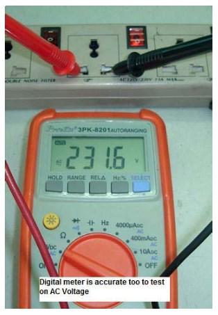
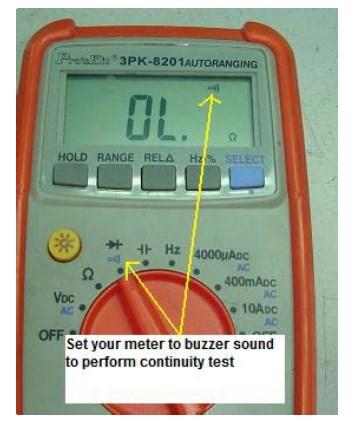
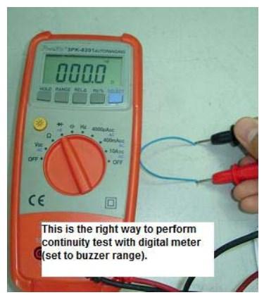
2 Testing Battery (DC) Testing AC Testing Wire 1 P a g e
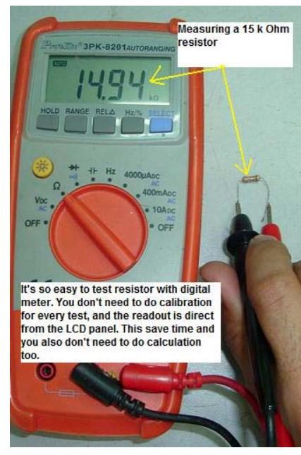
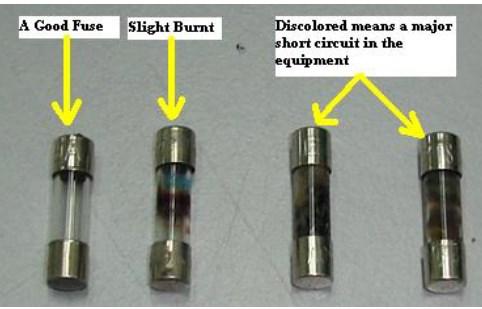
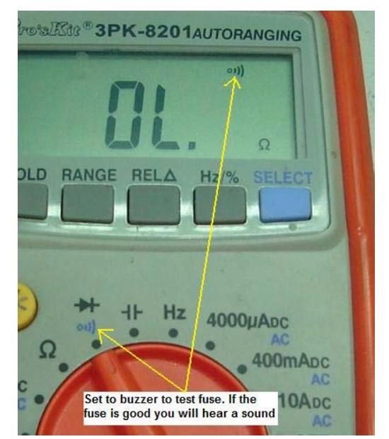
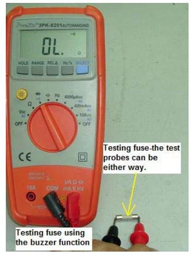
3 Resistor measurement Testing Fuse 2 P a g e
4 3 P a g e
5 Objective:- Study of series and parallel connection with lamp and switches. Equipments Required:- Bread-board, D.C. Voltage Supply, Switches, Lamp, Breadboard Connectors etc. Circuit Diagrams and Observation Table:- Series Connection :- Switch 1 Switch 2 D.C. Voltage Source (Switches are connected in series) Figure-1) Procedures: 1). Build the above circuit diagram on a bread-board by connecting the two switches and a given lamp. 2). Adjust a D.C. Voltage source at (5V) and connect it to the above circuit properly. 3). Observe the status of lamp by keeping the switch 1 and switch 2 at different positions i.e. (On or Off). 4). Write down your result in the observation (Table-1). 4 P a g e
6 Observation table for switches series connection: - (Table-1) D.C. Voltage Supply Position of Switch 1 Position of Switch2 Status of Lamp On or OFF Parallel Connection: - Switch 1 Switch 2 D.C. Voltage Source (Switches are connected in parallel) 5 P a g e
7 (Figure-2) Procedures: 1). Build the above circuit diagram on a bread-board by connecting the two switches and a given lamp. 2). Adjust a D.C. Voltage source at (5V) and connect it to the above circuit properly. 3). Observe the status of lamp by keeping the switch 1 and switch 2 at different positions i.e. (On or Off). 4). Write down your result in the observation (Table-2) Observation table for switches parallel connection: - (Table-2) D.C. Voltage Supply Position of Switch 1 Position of Switch2 Status of Lamp On or OFF Note: 1 means ON 0 means OFF. 6 P a g e
8 Objective: - Measurement of voltage across resistor by Digital Multi-Meter (D.M.M.) and current through resistor by Digital Multi-Meter (D.M.M.). Verify the results obtained by Ohm s Law. Equipment Required: - Bread-board, D.C. Voltage Supply, Digital Multi-Meter (D.M.M), Resistors, Breadboard Connectors etc. Circuit Diagram:- D.M.M. D.M.M. D.C. Voltage Source R VR Com V D.C. Voltage Source R Opened to connect D.M.M. I A Com (Voltage measurement across the resistor) resistor) (Figure-1) (Current measurement through the (Figure-2) Procedures: Part (A) 1). Build the above circuit diagram of (Figure-1) on a breadboard by connecting resistor R and D.C. Voltage source. 2). Adjust a D.C. Voltage source value as given in (Table-1). 3). Measure voltage VR across resistor R by using a digital multi-meter (D.M.M.) as shown in the above Circuit diagram of (Figure-1) and write down the measured value in the (Table-1). 4). Measure the current through resistor R by using a digital multi-meter (D.M.M.) as shown in the above circuit diagram of (Figure-2) and write down the measured value in the (Table-1). Observation table of VOLTAGE and CURRENT measurement: - 7 P a g e
9 S.No. V S R V R I [A] (Table-1) Part (B) 1). For (Figure-2) change the source voltage value zero (0). Measure and write down the current through resistor R in the (Table-2). 2). Increase voltage according to the (Table-2) and write down the measured values of current for each value of voltages. 3). Plot the graph between Vs on X-axis and I [m.a.] on Y-axis on the graph paper. Notice the relation between Voltage and Current. Observation table for graph data:- (Table-2) S.No. VS R1 I [m.a.] Note: i ). Digital Multi-Meter (D.M.M.) is connected in parallel for measuring voltage. Hence, no change/s in the built circuit is made to connect a D.M.M. ii). Digital Multi-Meter (D.M.M.) is connected in series for measuring current. Hence, one has to break (open) the built circuit to connect a D.M.M. 8 P a g e
10 iii). For plotting graph between Vs on X-axis and I [m.a.] following scales are recommended. X-axis big squares= 1V Y-axis big square= 2m.A. 9 P a g e
11 10 P a g e
12 Objective:- Measurement of voltage across the resistors connected in series and parallel. Equipment Required:- Bread-board, D.C. Voltage Supply, Digital Multi-Meter (D.M.M), Resistors, Breadboard Connectors etc. Circuit Diagram:- Series Connection :- D.M.M. R1 R2 V R1 Com V D.C. Voltage Source (Resistors are connected in series) (Figrue-1) Procedures: 1). Build the above circuit diagram on a breadboard by connecting the two resistors R1 and R2 in series. 2). Adjust a D.C. Voltage source value as given in (Table-1). 3). Measure voltage VR1 across resistor R1 by using a digital multi-meter (D.M.M.) as shown in the above circuit diagram of (Figure-1). 4). Similarly, measure the voltage VR2 across resistor R2, and voltage VT across (R1-R2). Notice the relation among VR1, VR2 and VT. 5). Change R1, R2 and D.C. Voltage as given in (Table-1) and write down the measured values of VR1, VR2 and VT in (Table-1). Observation table of VOLTAGEs for series connection: - S.No. VS R1 R2 VR1 VR2 VT K K (Table-1) K 2.2K P a g e
13 Circuit Diagram: - Parallel Connection: - D.C. Voltage Source R1 R2 D.M.M. V R1 Com V (Resistors connected in parallel) (Figure-2) Procedures: 1). Build the above circuit diagram of (Figure-2) on a breadboard by connecting the two resistors R1 and R2 in parallel. 2). Adjust a D.C. Voltage source value as given in the (Table-2). 3). Measure voltage VR1 across resistor R1 by using a digital multi-meter (D.M.M.) as shown in the above circuit diagram of (Figure-2). 4). Similarly, measure the voltage VR2 across resistor R2, and voltage VT across (R1-R2). Notice the relation among VR1, VR2, VT. 5). Change R1, R2 and D.C. Voltage as given in the (Table-2) and write down the measured values of VR1, VR2 and VT in (Table-2). Observation table of VOLTAGEs for parallel connection: - S.No. VS R1 R2 VR1 VR1 VT K K K 4.7K P a g e
14 Objective: - Measurement of current through the resistors connected in series and parallel. Equipment Required:- Breadboard, D.C. Voltage Supply, Digital Multi-Meter (D.M.M), Resistors, Breadboard Connectors etc. Circuit Diagram:- Series Connection:- D.C. Voltage Source I X R1 Y R2 Z D.M.M. I A Com Procedures: (Resistors connected in series) (Figure-1) 1). Build the above circuit diagram of (Figure-1) on a breadboard by connecting the two resistors R1 and R2 again in series. 2). Adjust a D.C. Voltage source value as given in the (Table-1). 3). Measure the current I through resistor R1 at point Y by using a digital multi-meter (D.M.M.) as shown in the above circuit diagram of (Figure-1). 4). Similarly, measure current I coming out of the source at point X and through resistor R2 at point Z. Notice the value of current measured at points X, Y and Z. 5). Change R1, R2 and D.C. Voltage value as given in the (Table-1) and write down the measured values of current I at X, Y and Z in (Table-1). Observation table of CURRENTs for series connection: - (Table-1). S.No. VS R1 R2 I at X [A] I at Y [A] I at Z [A] P a g e
15 Circuit Diagram: - Parallel Connection: - D.M.M. I R1 I T I 1 I T A Com D.C. Voltage Source I 2 R1 R2 (Resistors connected in parallel) (Figure-2) Procedures: 1). Build the above circuit diagram of (Figure-2) on a breadboard by connecting the two resistors R1 and R2 again in parallel. 2). Adjust a D.C. Voltage source value as given in the (Table-2). 3). Measure current I1 through resistor R1 by using a digital multi-meter (D.M.M.) as shown in the above circuit Diagram of (Figure-2). 4). Similarly, measure current I2 through resistor R2 and IT coming out of the source and entering into the source. Notice the relation between the currents I1, I2, and IT. 5). Change R1, R2 and D.C. Voltage value as given in the (Table-2)and write down the measured values of current I1, I2, and IT in (Table-2). Observation table of CURRENTs for parallel connection: - (Table-2) S.No. VS R1 R2 I1 [A] I2 [A] IT [A] Note: Digital Multi-Meter (D.M.M.) is connected in series while measuring current. Hence, one has to break (open) the circuit to connect a D.M.M. 14 P a g e
16 Objective: - Verify Kirchhoff s Voltage Law (KVL) and Kirchhoff s Current Law (KCL) using mesh and nodal analysis of the given circuit. Theory: Kirchhoff s Voltage Law states that the algebraic sum of all the voltages around any closed path (loop or mesh) is zero. Applying Kirchhoff s voltage law to the Loop1 and Loop2 in the circuit shown in Figure-1 gives: Loop1[ABEF]: (V1) + (V2) + (- Vs) = 0 ---(1) Loop2 [BCDE]: (V3) + (- V2) = 0 ---(2) Kirchhoff s Current Law states that the algebraic sum of all the currents at any node is zero. Or Algebraic sum of currents entering a node is equal to the algebraic sum of currents leaving the same node. Applying Kirchhoff s current law to the nodes B and E in the circuit shown in Figure-1 gives: At node B: Is = I1 + I2 ---(3) At node E: I1 + I2 = Is ---(4) Equipments Required: - Bread-board, D.C. Voltage Supply, Digital Multi-Meter (D.M.M), Resistors, Breadboard Connectors etc. Circuit Diagrams and Data Table: - D.C. Voltage Source VS = 11V A B C E (Figure-1) Procedures: 1). Build the above circuit given in (Figure-1) on a breadboard. 2). Set the D.C. Voltage source value as given in the (Table-1). I S I S F V 1 R1 Loop1 I 1 V 2 Loop2 R2 V 3 I 2 D R3 15 P a g e
17 3). Measure the voltages V1, V2, V3, VS and currents I1, I2, IS by D.M.M. and write down the values in the following (Table-1). 3). Verify the KVL for the Loop1 and Loop2 using equations (1) and (2). 4). Verify the KCL for node B and node E using equations (3) and (4). Observation table of Voltages and Currents for KVL and KCL :- S VS R1 R2 R3 V1 V2 V3 I1 I2 IS.No. [A] [A] [A] (Table-1) 16 P a g e
18 Objective: - Study of potentiometer as a voltage divider with and without load. Equipment Required: - Breadboard, D.C. Voltage Supply, Digital Multi-Meter (D.M.M), Potentiometer, Breadboard Connectors etc. Circuit Diagram: - D.M.M. D.M.M. R1 R2 e f d c b g a V R1 Com V V R2 Com V (Figure-1) Voltage divider no load Voltage divider with load Procedures: 1). Connect a potentiometer only of (220 Ω, 1K Ω,...) on a breadboard. 2). Adjust pointer of potentiometer at position a and measure resistance values R1 and R2 by using a digital multi-meter (D.M.M.) as shown in the circuit diagram of (Figure-1){Note: set your D.M.M. dialer to Ohm(Ω) position}. Write down the measured resistance values in (Table-1). 3). Similarly, adjust pointer of potentiometer at other positions b, c d, e, f g, and measure resistance values R1 and R2. Write down the measured resistance values for all positions in (Table-1). 4). Now connect a D.C. Voltage Source to the potentiometer as shown in (Figure-1). 17 P a g e
19 5). Adjust D.C. Voltage Source value to 10 V (it can be set to other values). 6). Adjust pointer of potentiometer at position a and measure the voltages VR1 and VR2 across R1 and R2 respectively, as shown in the (Figure-1) by digital multi-meter (D.M.M.) {Note: set your D.M.M. Dialer now to Voltage(V) position}. Write down the measured voltage values in (Table-1). 7). Similarly, adjust pointer of potentiometer at other positions b, c d, e, f g, and measure the voltages VR1 and VR2. Write down the measured voltages for all positions in (Table-1). 8). Observe the voltages VR1 and VR2 are increasing or decreasing as the values of R1 and R2 increasing or decreasing in the (Table-1). 9. Repeat the experiment for voltage divider with load. Observation table of potentiometer: - (Table-1) S.No. Pointer Position R1 R2 VR1 VR2 1 a b c d e f g h (till end point) 18 P a g e

20 19 P a g e
21 20 P a g e
22 Load (R L )=100 Ω /150 Ω S.No. Pointer Position R1 R2 VR1 VR2 1 a b c d e f g h (till end point) 21 P a g e
23 Load (R L )=1kΩ S.No. Pointer Position R1 R2 VR1 VR2 1 a b c d e f g h (till end point) 22 P a g e
24 23 P a g e
25 24 P a g e
26 25 P a g e

27 26 P a g e
28 Objective: To measure the fundamental parameters of the alternating current Sine Wave form. A sinusoidal alternating voltage. 1 = Peak, also amplitude, 2 = Peak-to-peak, 3 = RMS, 4 = Period Vp-p=Number of boxes on y-axis on oscilloscope *Volts/Div = T= Number of boxes on x-axis on oscilloscope *Time/Div = Formula 1) Frequency =1/T (Hz) 2) λ = c f (m) 3) ω = 2πf (rad/s) Calculate the Value 4) Vmax 5) Vp-p=2Vmax or 2Vpeak 6) Vrms= (Vp-p)/2 2 7) Vavg=(Vp-p)/π 27 P a g e

29 28 P a g e

30 29 P a g e
Laboratory 2 (drawn from lab text by Alciatore)
") Laboratory 2 (drawn from lab text by Alciatore) Instrument Familiarization and Basic Electrical Relations Required Components: 2 1k resistors 2 1M resistors 1 2k resistor Objectives This exercise is designed
Laboratory 2 (drawn from lab text by Alciatore) Instrument Familiarization and Basic Electrical Relations Required Components: 2 1k resistors 2 1M resistors 1 2k resistor Objectives This exercise is designed
UNIVERSITY OF NORTH CAROLINA AT CHARLOTTE Department of Electrical and Computer Engineering
 UNIVERSITY OF NORTH CAROLINA AT CHARLOTTE Department of Electrical and Computer Engineering EXPERIMENT 8 NETWORK ANALYSIS OBJECTIVES The purpose of this experiment is to mathematically analyze a circuit
Solution: Based on the slope of q(t): 20 A for 0 t 1 s dt = 0 for 3 t 4 s. 20 A for 4 t 5 s 0 for t 5 s 20 C. t (s) 20 C. i (A) Fig. P1.
: 20 A for 0 t 1 s dt = 0 for 3 t 4 s. 20 A for 4 t 5 s 0 for t 5 s 20 C. t (s) 20 C. i (A) Fig. P1.") Problem 1.24 The plot in Fig. P1.24 displays the cumulative charge q(t) that has entered a certain device up to time t. Sketch a plot of the corresponding current i(t). q 20 C 0 1 2 3 4 5 t (s) 20 C Figure
Problem 1.24 The plot in Fig. P1.24 displays the cumulative charge q(t) that has entered a certain device up to time t. Sketch a plot of the corresponding current i(t). q 20 C 0 1 2 3 4 5 t (s) 20 C Figure
University of Portland EE 271 Electrical Circuits Laboratory. Experiment: Kirchhoff's Laws and Voltage and Current Division
 University of Portland EE 271 Electrical Circuits Laboratory Experiment: Kirchhoff's Laws and Voltage and Current Division I. Objective The objective of this experiment is to determine the relationship
Lab Experiment No. 4
 Lab Experiment No. Kirchhoff s Laws I. Introduction In this lab exercise, you will learn how to read schematic diagrams of electronic networks, how to draw and use network graphs, how to transform schematics
ECE ECE285. Electric Circuit Analysis I. Spring Nathalia Peixoto. Rev.2.0: Rev Electric Circuits I
 ECE285 Electric Circuit Analysis I Spring 2014 Nathalia Peixoto Rev.2.0: 140124. Rev 2.1. 140813 1 Lab reports Background: these 9 experiments are designed as simple building blocks (like Legos) and students
Ahsanullah University of Science and Technology
 Ahsanullah University of Science and Technology Department of Electrical and Electronic Engineering AU ST /E EE LABORATORY MANUAL FOR ELECTRICAL AND ELECTRONIC SESSIONAL COURSE Student Name : Student ID
3. Voltage and Current laws
 1 3. Voltage and Current laws 3.1 Node, Branches, and loops A branch represents a single element such as a voltage source or a resistor A node is the point of the connection between two or more elements
Ohm s Law and Electrical Circuits
 Ohm s Law and Electrical Circuits INTRODUCTION In this experiment, you will measure the current-voltage characteristics of a resistor and check to see if the resistor satisfies Ohm s law. In the process
ELECTRICAL CIRCUITS LABORATORY MANUAL (II SEMESTER)
") ELECTRICAL CIRCUITS LABORATORY MANUAL (II SEMESTER) LIST OF EXPERIMENTS. Verification of Ohm s laws and Kirchhoff s laws. 2. Verification of Thevenin s and Norton s Theorem. 3. Verification of Superposition
ELECTRICAL CIRCUITS LABORATORY MANUAL (II SEMESTER) LIST OF EXPERIMENTS. Verification of Ohm s laws and Kirchhoff s laws. 2. Verification of Thevenin s and Norton s Theorem. 3. Verification of Superposition
Laboratory 2. Lab 2. Instrument Familiarization and Basic Electrical Relations. Required Components: 2 1k resistors 2 1M resistors 1 2k resistor
 Laboratory 2 nstrument Familiarization and Basic Electrical Relations Required Components: 2 1k resistors 2 1M resistors 1 2k resistor 2.1 Objectives This exercise is designed to acquaint you with the
Sapphire Instruments Co., Ltd. Calibration Procedure of SI-9101
 Sapphire Instruments Co., Ltd. Calibration Procedure of SI-9101 1. How to open the case, please follow the steps. 1.1 Remove the battery lid. 1.2 You will see the two screws and loosen them. Fig. 1 1.3
Sirindhorn International Institute of Technology Thammasat University
 Sirindhorn International Institute of Technology Thammasat University School of Information, Computer and Communication Technology COURSE : ECS 34 Basic Electrical Engineering Lab INSTRUCTOR : Dr. Prapun
Objective of the Lecture
 Objective of the Lecture Present Kirchhoff s Current and Voltage Laws. Chapter 5.6 and Chapter 6.3 Principles of Electric Circuits Chapter4.6 and Chapter 5.5 Electronics Fundamentals or Electric Circuit
Experiment #3 Kirchhoff's Laws
 SAN FRANCSC STATE UNVERSTY ELECTRCAL ENGNEERNG Kirchhoff's Laws bjective To verify experimentally Kirchhoff's voltage and current laws as well as the principles of voltage and current division. ntroduction
ELECTRIC CIRCUITS CMPE 253 DEPARTMENT OF COMPUTER ENGINEERING LABORATORY MANUAL ISHIK UNIVERSITY
 ELECTRIC CIRCUITS CMPE 253 DEPARTMENT OF COMPUTER ENGINEERING LABORATORY MANUAL ISHIK UNIVERSITY 2017-2018 1 WEEK EXPERIMENT TITLE NUMBER OF EXPERIMENT No Meeting Instructional Objective 2 Tutorial 1 3
Power Electronics Laboratory-2 Uncontrolled Rectifiers
 Roll. No: Checked By: Date: Grade: Power Electronics Laboratory-2 and Uncontrolled Rectifiers Objectives: 1. To analyze the working and performance of a and half wave uncontrolled rectifier. 2. To analyze
EEE 2101 Circuit Theory I - Laboratory 1 Kirchoff s Laws, Series-Parallel Circuits
 ame & Surname: D: Date: EEE 20 Circuit Theory - Laboratory Kirchoff s Laws, Series-Parallel Circuits List of topics for this laboratory: Ohm s Law Kirchoff s Current Law(KCL) Kirchoff s Voltage Law(KVL)
Prelab 4 Millman s and Reciprocity Theorems
 Prelab 4 Millman s and Reciprocity Theorems I. For the circuit in figure (4-7a) and figure (4-7b) : a) Calculate : - The voltage across the terminals A- B with the 1kΩ resistor connected. - The current
ECE 53A: Fundamentals of Electrical Engineering I
 ECE 53A: Fundamentals of Electrical Engineering I Laboratory Assignment #1: Instrument Operation, Basic Resistor Measurements and Kirchhoff s Laws Fall 2007 General Guidelines: - Record data and observations
The University of Jordan Mechatronics Engineering Department Electronics Lab.( ) Experiment 1: Lab Equipment Familiarization
 Experiment 1: Lab Equipment Familiarization") The University of Jordan Mechatronics Engineering Department Electronics Lab.(0908322) Experiment 1: Lab Equipment Familiarization Objectives To be familiar with the main blocks of the oscilloscope and
The University of Jordan Mechatronics Engineering Department Electronics Lab.(0908322) Experiment 1: Lab Equipment Familiarization Objectives To be familiar with the main blocks of the oscilloscope and
I. Objectives Upon completion of this experiment, the student should be able to: Ohm s Law
 EENG-201 Experiment # 1 Series Circuit and Parallel Circuits I. Objectives Upon completion of this experiment, the student should be able to: 1. ead and use the resistor color code. 2. Use the digital
Announcements. To stop blowing fuses in the lab, note how the breadboards are wired. EECS 42, Spring 2005 Week 3a 1
 Announcements New topics: Mesh (loop) method of circuit analysis Superposition method of circuit analysis Equivalent circuit idea (Thevenin, Norton) Maximum power transfer from a circuit to a load To stop
BME 3512 Bioelectronics Laboratory Two - Passive Filters
 BME 35 Bioelectronics Laboratory Two - Passive Filters Learning Objectives: Understand the basic principles of passive filters. Laboratory Equipment: Agilent Oscilloscope Model 546A Agilent Function Generator
EE2210 Laboratory Project 1 Fall 2013 Function Generator and Oscilloscope
 EE2210 Laboratory Project 1 Fall 2013 Function Generator and Oscilloscope For students to become more familiar with oscilloscopes and function generators. Pre laboratory Work Read the TDS 210 Oscilloscope
Source Transformations
 Source Transformations Introduction The circuits in this set of problems consist of independent sources, resistors and a meter. In particular, these circuits do not contain dependent sources. Each of these
Announcements. To stop blowing fuses in the lab, note how the breadboards are wired. EECS 42, Spring 2005 Week 3a 1
 Announcements New topics: Mesh (loop) method of circuit analysis Superposition method of circuit analysis Equivalent circuit idea (Thevenin, Norton) Maximum power transfer from a circuit to a load To stop
Purpose: 1) to investigate the electrical properties of a diode; and 2) to use a diode to construct an AC to DC converter.
 to investigate the electrical properties of a diode; and 2) to use a diode to construct an AC to DC converter.") Name: Partner: Partner: Partner: Purpose: 1) to investigate the electrical properties of a diode; and 2) to use a diode to construct an AC to DC converter. The Diode A diode is an electrical device which
Name: Partner: Partner: Partner: Purpose: 1) to investigate the electrical properties of a diode; and 2) to use a diode to construct an AC to DC converter. The Diode A diode is an electrical device which
BME (311) Electric Circuits lab
 Electric Circuits lab") Summer 2016 Facility of Engineering Department of Biomedical Engineering BME (311) Electric Circuits lab Prepared By: Eng. Hala Amari Supervised By: Dr. Areen AL-Bashir Table of Contents Experiment # 1
Summer 2016 Facility of Engineering Department of Biomedical Engineering BME (311) Electric Circuits lab Prepared By: Eng. Hala Amari Supervised By: Dr. Areen AL-Bashir Table of Contents Experiment # 1
Sonoma State University Department of Engineering Science Spring 2017
 EE 110 Introduction to Engineering & Laboratory Experience Saeid Rahimi, Ph.D. Lab 4 Introduction to AC Measurements (I) AC signals, Function Generators and Oscilloscopes Function Generator (AC) Battery
EE 210: CIRCUITS AND DEVICES
 EE 210: CIRCUITS AND DEVICES LAB #3: VOLTAGE AND CURRENT MEASUREMENTS This lab features a tutorial on the instrumentation that you will be using throughout the semester. More specifically, you will see
Bakiss Hiyana binti Abu Bakar JKE, POLISAS BHAB
 1 Bakiss Hiyana binti Abu Bakar JKE, POLISAS 1. Explain AC circuit concept and their analysis using AC circuit law. 2. Apply the knowledge of AC circuit in solving problem related to AC electrical circuit.
Lecture # 4 Network Analysis
 CPEN 206 Linear Circuits Lecture # 4 Network Analysis Dr. Godfrey A. Mills Email: gmills@ug.edu.gh Phone: 026-907-3163 February 22, 2016 Course TA David S. Tamakloe 1 What is Network Technique o Network
Questions Bank of Electrical Circuits
 Questions Bank of Electrical Circuits 1. If a 100 resistor and a 60 XL are in series with a 115V applied voltage, what is the circuit impedance? 2. A 50 XC and a 60 resistance are in series across a 110V
Lab 2: Common Emitter Design: Part 2
 Lab 2: Common Emitter Design: Part 2 ELE 344 University of Rhode Island, Kingston, RI 02881-0805, U.S.A. 1 Linearity in High Gain Amplifiers The common emitter amplifier, shown in figure 1, will provide
MEMORIAL UNIVERSITY OF NEWFOUNDLAND. Faculty of Engineering and Applied Science. Laboratory Manual for. Eng Circuit Analysis (2011)
") MEMORIAL UNIVERSITY OF NEWFOUNDLAND Faculty of Engineering and Applied Science Laboratory Manual for Eng. 3821 Circuit Analysis (2011) Instructor: E. Gill PREFACE The laboratory exercises in this manual
MEMORIAL UNIVERSITY OF NEWFOUNDLAND Faculty of Engineering and Applied Science Laboratory Manual for Eng. 3821 Circuit Analysis (2011) Instructor: E. Gill PREFACE The laboratory exercises in this manual
LRC Circuit PHYS 296 Your name Lab section
 LRC Circuit PHYS 296 Your name Lab section PRE-LAB QUIZZES 1. What will we investigate in this lab? 2. Figure 1 on the following page shows an LRC circuit with the resistor of 1 Ω, the capacitor of 33
Module 2: AC Measurements. Measurements and instrumentation
 Module 2: AC Measurements Measurements and instrumentation Watch the following video Module objectives Upon successful completion of this module, students should be able to: Familiarise with the definition
POLYTECHNIC UNIVERSITY Electrical Engineering Department. EE SOPHOMORE LABORATORY Experiment 3 The Oscilloscope
 POLYTECHNIC UNIVERSITY Electrical Engineering Department EE SOPHOMORE LABORATORY Experiment 3 The Oscilloscope Modified for Physics 18, Brooklyn College I. Overview of the Experiment The main objective
BME/ISE 3511 Laboratory One - Laboratory Equipment for Measurement. Introduction to biomedical electronic laboratory instrumentation and measurements.
 BME/ISE 3511 Laboratory One - Laboratory Equipment for Measurement Learning Objectives: Introduction to biomedical electronic laboratory instrumentation and measurements. Supplies and Components: Breadboard
EE42: Running Checklist of Electronics Terms Dick White
 EE42: Running Checklist of Electronics Terms 14.02.05 Dick White Terms are listed roughly in order of their introduction. Most definitions can be found in your text. Terms2 TERM Charge, current, voltage,
Lab #2 Voltage and Current Division
 In this experiment, we will be investigating the concepts of voltage and current division. Voltage and current division is an application of Kirchoff s Laws. Kirchoff s Voltage Law Kirchoff s Voltage Law
Exp. 1 USE OF BASIC ELECTRONIC MEASURING INSTRUMENTS, PART I
 Exp. 1 USE OF BASIC ELECTRONIC MEASURING INSTRUMENTS, PART I PURPOSE: To become familiar with some of the instruments used in this and subsequent labs. To develop proper laboratory procedures relative
Velleman Arbitrary Function Generator: Windows 7 by Mr. David Fritz
 Velleman Arbitrary Function Generator: Windows 7 by Mr. David Fritz You should already have the drivers installed Launch the scope control software. Start > Programs > Velleman > PcLab2000LT What if the
ECE 2274 Lab 1 (Intro)
") ECE 2274 Lab 1 (Intro) Richard Dumene: Spring 2018 Revised: Richard Cooper: Spring 2018 Forward (DO NOT TURN IN) The purpose of this lab course is to familiarize you with high-end lab equipment, and train
ECE 2274 Lab 1 (Intro) Richard Dumene: Spring 2018 Revised: Richard Cooper: Spring 2018 Forward (DO NOT TURN IN) The purpose of this lab course is to familiarize you with high-end lab equipment, and train
Group: Names: Resistor Band Colors Measured Value ( ) R 1 : 1k R 2 : 1k R 3 : 2k R 4 : 1M R 5 : 1M
 R 1 : 1k R 2 : 1k R 3 : 2k R 4 : 1M R 5 : 1M") 2.4 Laboratory Procedure / Summary Sheet Group: Names: (1) Select five separate resistors whose nominal values are listed below. Record the band colors for each resistor in the table below. Then connect
2.4 Laboratory Procedure / Summary Sheet Group: Names: (1) Select five separate resistors whose nominal values are listed below. Record the band colors for each resistor in the table below. Then connect
PHYS Contemporary Physics Laboratory Laboratory Exercise: LAB 01 Resistivity, Root-mean-square Voltage, Potentiometer (updated 1/25/2017)
") PHYS351001 Contemporary Physics Laboratory Laboratory Exercise: LAB 01 Resistivity, Root-mean-square Voltage, Potentiometer (updated 1/25/2017) PART I: SOME FUNDAMENTAL CONCEPTS: 1. Limits on accuracy
PHYS351001 Contemporary Physics Laboratory Laboratory Exercise: LAB 01 Resistivity, Root-mean-square Voltage, Potentiometer (updated 1/25/2017) PART I: SOME FUNDAMENTAL CONCEPTS: 1. Limits on accuracy
PHYSICS 221 LAB #6: CAPACITORS AND AC CIRCUITS
 Name: Partners: PHYSICS 221 LAB #6: CAPACITORS AND AC CIRCUITS The electricity produced for use in homes and industry is made by rotating coils of wire in a magnetic field, which results in alternating
ENG 100 Lab #2 Passive First-Order Filter Circuits
 ENG 100 Lab #2 Passive First-Order Filter Circuits In Lab #2, you will construct simple 1 st -order RL and RC filter circuits and investigate their frequency responses (amplitude and phase responses).
EE 368 Electronics Lab. Experiment 10 Operational Amplifier Applications (2)
") EE 368 Electronics Lab Experiment 10 Operational Amplifier Applications (2) 1 Experiment 10 Operational Amplifier Applications (2) Objectives To gain experience with Operational Amplifier (Op-Amp). To
EE 368 Electronics Lab Experiment 10 Operational Amplifier Applications (2) 1 Experiment 10 Operational Amplifier Applications (2) Objectives To gain experience with Operational Amplifier (Op-Amp). To
University of Jordan School of Engineering Electrical Engineering Department. EE 204 Electrical Engineering Lab
 University of Jordan School of Engineering Electrical Engineering Department EE 204 Electrical Engineering Lab EXPERIMENT 1 MEASUREMENT DEVICES Prepared by: Prof. Mohammed Hawa EXPERIMENT 1 MEASUREMENT
ES250: Electrical Science. HW6: The Operational Amplifier
 ES250: Electrical Science HW6: The Operational Amplifier Introduction This chapter introduces the operational amplifier or op amp We will learn how to analyze and design circuits that contain op amps,
Ohm's Law and DC Circuits
 Physics Lab II Ohm s Law Name: Partner: Partner: Partner: Ohm's Law and DC Circuits EQUIPMENT NEEDED: Circuits Experiment Board Two Dcell Batteries Wire leads Multimeter 100, 330, 560, 1k, 10k, 100k, 220k
Electrical Circuits I (ENGR 2405) Chapter 2 Ohm s Law, KCL, KVL, Resistors in Series/Parallel
 Chapter 2 Ohm s Law, KCL, KVL, Resistors in Series/Parallel") Electrical Circuits I (ENG 2405) Chapter 2 Ohm s Law, KCL, KVL, esistors in Series/Parallel esistivity Materials tend to resist the flow of electricity through them. This property is called resistance
Electrical Circuits I (ENG 2405) Chapter 2 Ohm s Law, KCL, KVL, esistors in Series/Parallel esistivity Materials tend to resist the flow of electricity through them. This property is called resistance
UNIVERSITY OF TECHNOLOGY, JAMAICA School of Engineering -
 UNIVERSITY OF TECHNOLOGY, JAMAICA School of Engineering - Electrical Engineering Science Laboratory Manual Table of Contents Safety Rules and Operating Procedures... 3 Troubleshooting Hints... 4 Experiment
Electronic Circuits Laboratory EE462G Lab #3. Diodes, Transfer Characteristics, and Clipping Circuits
 Electronic Circuits Laboratory EE46G Lab #3 Diodes, Transfer Characteristics, and Clipping Circuits Instrumentation This lab requires: Function Generator and Oscilloscope (as in Lab ) Tektronix s PS 80
Prepare for this experiment!
 Notes on Experiment #7 Prepare for this experiment! During this experiment you will be building the most elaborate circuit of the term. (See Figure 1. below for circuit diagram and values.) You will also
Lab #5 ENG RC Circuits
 Name:. Lab #5 ENG 220-001 Date: Learning objectives of this experiment is that students will be able to: Measure the effects of frequency upon an RC circuit Calculate and understand circuit current, impedance,
PHY203: General Physics III Lab page 1 of 5 PCC-Cascade. Lab: AC Circuits
 PHY203: General Physics III Lab page 1 of 5 Lab: AC Circuits OBJECTIVES: EQUIPMENT: Universal Breadboard (Archer 276-169) 2 Simpson Digital Multimeters (464) Function Generator (Global Specialties 2001)*
PHYS 1402 General Physics II Experiment 5: Ohm s Law
 PHYS 1402 General Physics II Experiment 5: Ohm s Law Student Name Objective: To investigate the relationship between current and resistance for ordinary conductors known as ohmic conductors. Theory: For
Fig [5]
![Fig [5]](/thumbs/82/85456687.jpg "Fig [5]") 1 (a) Fig. 4.1 shows the I-V characteristic of a light-emitting diode (LED). 40 I / 10 3 A 30 20 10 0 1.0 1.5 2.0 V / V Fig. 4.1 (i) In Describe the significant features of the graph in terms of current,
1 (a) Fig. 4.1 shows the I-V characteristic of a light-emitting diode (LED). 40 I / 10 3 A 30 20 10 0 1.0 1.5 2.0 V / V Fig. 4.1 (i) In Describe the significant features of the graph in terms of current,
ET1210: Module 5 Inductance and Resonance
 Part 1 Inductors Theory: When current flows through a coil of wire, a magnetic field is created around the wire. This electromagnetic field accompanies any moving electric charge and is proportional to
EGR 101 LABORATORY 1 APPLICATION OF ALGEBRA IN ENGINEERING Wright State University
 EGR 101 LABORATORY 1 APPLCATON OF ALGEBRA N ENGNEERNG Wright State University OBJECTVE: The objective of this laboratory is to illustrate applications of algebra (lines and quadratics) in engineering.
SINUSOIDS February 4, ELEC-281 Network Theory II Wentworth Institute of Technology. Bradford Powers Ryan Ferguson Richard Lupa Benjamin Wolf
 SINUSOIDS February 4, 28 ELEC-281 Network Theory II Wentworth Institute of Technology Bradford Powers Ryan Ferguson Richard Lupa Benjamin Wolf Abstract: Sinusoidal waveforms are studied in three circuits:
13 th Asian Physics Olympiad India Experimental Competition Wednesday, 2 nd May 2012
 13 th Asian Physics Olympiad India Experimental Competition Wednesday, nd May 01 Please first read the following instructions carefully: 1. The time available is ½ hours for each of the two experimental
CHARACTERISTICS OF OPERATIONAL AMPLIFIERS - II
 CHARACTERISTICS OF OPERATIONAL AMPLIFIERS - II OBJECTIVE The purpose of the experiment is to examine non-ideal characteristics of an operational amplifier. The characteristics that are investigated include
LABORATORY 3 v1 CIRCUIT ELEMENTS
 University of California Berkeley Department of Electrical Engineering and Computer Sciences EECS 100, Professor Bernhard Boser LABORATORY 3 v1 CIRCUIT ELEMENTS The purpose of this laboratory is to familiarize
ELECTRICAL CIRCUITS LABORATORY LAB MANUAL. Prepared by
 ELECTRICAL CIRCUITS LABORATORY LAB MANUAL Year : 2016-2017 Subject Code : AEE102 Regulations : R16 Class : I B.Tech II Semester Branch : ECE / EEE Prepared by Mr.P.Sridhar (Professor/HOD) Mr.G.Hari krishna
Lab 8 - INTRODUCTION TO AC CURRENTS AND VOLTAGES
 08-1 Name Date Partners ab 8 - INTRODUCTION TO AC CURRENTS AND VOTAGES OBJECTIVES To understand the meanings of amplitude, frequency, phase, reactance, and impedance in AC circuits. To observe the behavior
Chapter 8. Constant Current Sources
 Chapter 8 Methods of Analysis Constant Current Sources Maintains same current in branch of circuit Doesn t matter how components are connected external to the source Direction of current source indicates
EE 210 Lab Exercise #5: OP-AMPS I
 EE 210 Lab Exercise #5: OP-AMPS I ITEMS REQUIRED EE210 crate, DMM, EE210 parts kit, T-connector, 50Ω terminator, Breadboard Lab report due at the ASSIGNMENT beginning of the next lab period Data and results
3.4 The Single-Loop Circuit Single-loop circuits
 25 3.4 The Single-Loop Circuit Single-loop circuits Elements are connected in series All elements carry the same current We shall determine The current through each element The voltage across each element
Unit-1(A) Circuit Analysis Techniques
 Circuit Analysis Techniques") Unit-1(A Circuit Analysis Techniques Basic Terms used in a Circuit 1. Node :- It is a point in a circuit where two or more circuit elements are connected together. 2. Branch :- It is that part of a network
Unit-1(A Circuit Analysis Techniques Basic Terms used in a Circuit 1. Node :- It is a point in a circuit where two or more circuit elements are connected together. 2. Branch :- It is that part of a network
INTRODUCTION TO ENGINEERING AND LABORATORY EXPERIENCE Spring, 2015
 INTRODUCTION TO ENGINEERING AND LABORATORY EXPERIENCE Spring, 2015 Saeid Rahimi, Ph.D. Jack Ou, Ph.D. Engineering Science Sonoma State University A SONOMA STATE UNIVERSITY PUBLICATION CONTENTS 1 Electronic
1 xx refers to the Figure number; 1 for Figure 1, 2 for Figure 2, etc.
 Lab Experiment No. Voltage and Current Maps I. Introduction The purpose of this lab is to gain additional familiarity with making measurements on electrical networks. The experiments involved in this lab
EE215 FUNDAMENTALS OF ELECTRICAL ENGINEERING
 EE215 FUNDAMENTALS OF ELECTRICAL ENGINEERING Tai-Chang Chen University of Washington, Bothell Spring 2010 EE215 1 1 WEEK 2 SIMPLE RESISTIVE CIRCUITS April 9 th, 2010 TC Chen UWB 2010 EE215 2 2 QUESTIONS
APPENDIX D DISCUSSION OF ELECTRONIC INSTRUMENTS
 APPENDIX D DISCUSSION OF ELECTRONIC INSTRUMENTS DC POWER SUPPLIES We will discuss these instruments one at a time, starting with the DC power supply. The simplest DC power supplies are batteries which
On-Line Students Analog Discovery 2: Arbitrary Waveform Generator (AWG). Two channel oscilloscope
. Two channel oscilloscope") EET 150 Introduction to EET Lab Activity 5 Oscilloscope Introduction Required Parts, Software and Equipment Parts Figure 1, Figure 2, Figure 3 Component /Value Quantity Resistor 10 kω, ¼ Watt, 5% Tolerance
EET 150 Introduction to EET Lab Activity 5 Oscilloscope Introduction Required Parts, Software and Equipment Parts Figure 1, Figure 2, Figure 3 Component /Value Quantity Resistor 10 kω, ¼ Watt, 5% Tolerance
Basic Electronic Devices and Circuits EE 111 Electrical Engineering Majmaah University 2 nd Semester 1432/1433 H. Chapter 2. Diodes and Applications
 Basic Electronic Devices and Circuits EE 111 Electrical Engineering Majmaah University 2 nd Semester 1432/1433 H Chapter 2 Diodes and Applications 1 Diodes A diode is a semiconductor device with a single
10Vdc. Figure 1. Schematics for verifying Kirchhoff's Laws
 ECE 231 Laboratory Exercise 2 Laboratory Group (Names) OBJECTVE Verify Kirchhoff s voltage law Verify Kirchhoff s current law Gain experience in using both an ammeter and voltmeter Construct two (2) circuits
Lab #1 Help Document. This lab will be completed in room 335 CTB. You will need to partner up for this lab in groups of two.
 Lab #1 Help Document This help document will be structured as a walk-through of the lab. We will include instructions about how to write the report throughout this help document. This lab will be completed
2 AC and RMS. To pass this lab you must solve tasks 1-2. Tasks 3 and 4 are included in the grading of the course.
 2 AC and RMS Purpose of the lab: to familiarize yourself with the oscilloscope to familiarize yourself with AC voltages and different waveforms to study RMS and average values In this lab, you have the
Electronics - PHYS 2371/2
 TODAY Quick Review-Basics Alternating Current, Ch-7 - RMS - problem 7-1 Elements of AC Circuits, Ch-8 - resistor, capacitor, inductors(l) - impedance (Z), reactance (X) (video break) Step Function Analysis,
OSCILLOSCOPES, MULTIMETERS, & STRAIN GAGES
 Community College of Allegheny County Unit 1 Page 1 OSCILLOSCOPES, MULTIMETERS, & STRAIN GAGES The Overweight Sub That Cost Billions: After Spain invested $2.7 billion in a program for diesel-electric
Circuit Analysis-II. Circuit Analysis-II Lecture # 2 Wednesday 28 th Mar, 18
 Circuit Analysis-II Angular Measurement Angular Measurement of a Sine Wave ü As we already know that a sinusoidal voltage can be produced by an ac generator. ü As the windings on the rotor of the ac generator
Lab 3: AC Low pass filters (version 1.3)
") Lab 3: AC Low pass filters (version 1.3) WARNING: Use electrical test equipment with care! Always double-check connections before applying power. Look for short circuits, which can quickly destroy expensive
Lab 3: AC Low pass filters (version 1.3) WARNING: Use electrical test equipment with care! Always double-check connections before applying power. Look for short circuits, which can quickly destroy expensive
Diodes This week, we look at switching diodes, LEDs, and diode rectification. Be sure to bring a flash drive for recording oscilloscope traces.
 Diodes This week, we look at switching diodes, LEDs, and diode rectification. Be sure to bring a flash drive for recording oscilloscope traces. 1. Basic diode characteristics Build the circuit shown in
electronics fundamentals
 electronics fundamentals circuits, devices, and applications THOMAS L. FLOYD DAVID M. BUCHLA chapter 6 Identifying series-parallel relationships Most practical circuits have combinations of series and
QUESTION BANK ETE (17331) CM/IF. Chapter1: DC Circuits
 CM/IF. Chapter1: DC Circuits") QUESTION BANK ETE (17331) CM/IF Chapter1: DC Circuits Q1. State & explain Ohms law. Also explain concept of series & parallel circuit with the help of diagram. 3M Q2. Find the value of resistor in fig.
QUESTION BANK ETE (17331) CM/IF Chapter1: DC Circuits Q1. State & explain Ohms law. Also explain concept of series & parallel circuit with the help of diagram. 3M Q2. Find the value of resistor in fig.
EE283 Laboratory Exercise 1-Page 1
 EE283 Laboratory Exercise # Basic Circuit Concepts Objectives:. To become familiar with the DC Power Supply unit, analog and digital multi-meters, fixed and variable resistors, and the use of solderless
Lab 1 - Intro to DC Circuits
 Objectives Pre-Lab Background Equipment List Procedure Equipment Familiarization Student PC Board DC Power Supply Digital Multimeter Power Supply Cont Decade Box Ohms Law and Power Dissipation Current
LABORATORY 5 v3 OPERATIONAL AMPLIFIER
 University of California Berkeley Department of Electrical Engineering and Computer Sciences EECS 100, Professor Bernhard Boser LABORATORY 5 v3 OPERATIONAL AMPLIFIER Integrated operational amplifiers opamps
Lab 1: Basic RL and RC DC Circuits
 Name- Surname: ID: Department: Lab 1: Basic RL and RC DC Circuits Objective In this exercise, the DC steady state response of simple RL and RC circuits is examined. The transient behavior of RC circuits
EE 2274 DIODE OR GATE & CLIPPING CIRCUIT
 EE 2274 DIODE OR GATE & CLIPPING CIRCUIT Prelab Part I: Wired Diode OR Gate LTspice use 1N4002 1. Design a diode OR gate, Figure 1 in which the maximum current thru R1 I R1 = 9mA assume Vin = 5Vdc. Design
Basic DC Power Supply
 Basic DC Power Supply Equipment: 1. Analog Oscilloscope 2. Digital multimeter 3. Experimental board and connectors. Objectives: 1. To understand the basic DC power supply both half wave and full wave rectifier.
CMPE 306. Lab III: Network Laws, Current and Voltage Measurements
 CMPE 306 Lab III: Network Laws, Current and Voltage Measurements Created by: E.F.C. LaBerge based on previous unattributed lab description July 2013 Revised Fall 2016 E. F. C. LaBerge and Aksel Thomas
Electrical Engineering Fundamentals
 Electrical Engineering Fundamentals EE-238 Sheet 1 Series Circuits 1- For the circuits shown below, the total resistance is specified. Find the unknown resistance and the current for each circuit. 12.6
Experiment #2 Half Wave Rectifier
 PURPOSE: ELECTRONICS 224 ETR620S Experiment #2 Half Wave Rectifier This laboratory session acquaints you with the operation of a diode power supply. You will study the operation of half-wave and the effect
ENGR 120 LAB #2 Electronic Tools and Ohm s Law
 ENGR 120 LAB #2 Electronic Tools and Ohm s Law Objectives Understand how to use a digital multi-meter, power supply and proto board and apply that knowledge to constructing circuits to demonstrate ohm
UNIVERSITY OF CALIFORNIA, BERKELEY. EE40: Introduction to Microelectronic Circuits Lab 1. Introduction to Circuits and Instruments Guide
 UNERSTY OF CALFORNA, BERKELEY EE40: ntroduction to Microelectronic Circuits Lab 1 ntroduction to Circuits and nstruments Guide 1. Objectives The electronic circuit is the basis for all branches of electrical