EVALUATION OF ALTERNATIVE DOWEL BAR MATERIALS AND COATINGS
|
|
|
- Alexia Bruce
- 5 years ago
- Views:
Transcription


1 EVALUATION OF ALTERNATIVE DOWEL BAR MATERIALS AND COATINGS Final Report Roger M. Larson Kurt D. Smith Prepared For: Ohio Department of Transportation Office of Research and Development In Cooperation With: U.S. Department of Transportation Federal Highway Administration State Job Number TPF-5(188) November 2011
2
3 1. Report No. FHWA/OH-2011/19 4. Title and subtitle 2. Government Accession No. 3. Recipient's Catalog No. 5. Report Date Evaluation of Alternative Dowel Bar Materials and Coatings November Performing Organization Code 7. Author(s) Roger M. Larson and Kurt D. Smith 9. Performing Organization Name and Address Applied Pavement Technology, Inc. 115 W. Main Street, Suite 400 Urbana, Illinois Sponsoring Agency Name and Address Ohio Department of Transportation 1980 West Broad Street Columbus, Ohio Supplementary Notes 8. Performing Organization Report No. 10. Work Unit No. (TRAIS) 11. Contract or Grant No / TPF-5(188) 13. Type of Report and Period Covered Final Report October 2008 to October Sponsoring Agency Code This work was initiated under the May 1988 HITEC Final Evaluation Plan. A detailed summary of that effort was provided in a draft Interim Report dated March 31, Abstract This study provided for a continuation of the long-term performance evaluation of 1.5-in (38-mm) diameter FRP dowels and Type 304 stainless steel solid dowels or mortar-filled tubes compared to epoxy-coated dowels. This primarily included an evaluation of load transfer efficiency (LTE) based on FWD testing, but also included a limited evaluation of faulting and ride. In addition, some FWD testing and coring was conducted on older projects (15 to 30+ years old) to evaluate the long-term corrosion protection provided by epoxy coatings. The 1.5-in (38 mm) FRP dowels with polyester resin and E-glass exhibited generally low LTE values, and are not providing performance comparable to that of the 1.5-in (38-mm) epoxy-coated mild steel dowel bars. The evaluation of alternative stainless steel clad dowels and concrete filled stainless steel tubes or pipes (Type 304 or Type 316) was inconclusive due to the small sample and the relatively short (14 years maximum) evaluation period, but it appears that they will perform satisfactorily in excess of 30 years given the minimal deterioration observed. Based on the coring of the older pavement projects, the life of the epoxy coating on mild steel dowels evaluated in Ohio and Wisconsin appears to be in the 25 to 30-year range. Many of the epoxy-coated dowels retrieved from in-service pavements revealed that the epoxy coating was debonded from the mild steel dowel and the surface of the mild steel dowel under the coating was pitted and rusted. In most cases, however, there was no significant loss of cross section. A review of two older projects in Ohio constructed with plastic-coated dowels indicated that those dowels were in excellent condition after 33 years. The overall condition of these projects was also very good, with little if any visible joint deterioration. Because plastic-coated dowels are similar to epoxy-coated dowels in terms of costs, they appear to be a cost-effective alternative to conventional epoxy-coated dowels. 17. Key Words Concrete pavement, joint design, dowel bar, load transfer, alternative dowel bar, epoxy-coating, fiber reinforced polymer, stainless steel, plastic-coating 18. Distribution Statement No restrictions. This document is available to the public through the National Technical Information Service, Springfield, Virginia Security Classif. (of this report) Unclassified Form DOT F (8-72) 20. Security Classif. (of this page) Unclassified 21. No. of Pages 218 Reproduction of completed pages authorized 22. Price
4
5 EVALUATION OF ALTERNATIVE DOWEL BAR MATERIALS AND COATINGS FINAL REPORT Prepared By: Roger M. Larson, P.E. Kurt D. Smith, P.E. Research Conducted By: Applied Pavement Technology, Inc. 115 W. Main Street, Suite 400 Urbana, Illinois Performed Under: State Job Number Agreement Number Sponsored By: Ohio Department of Transportation In Cooperation With: U.S. Department of Transportation Federal Highway Administration November 2011
6
7 Disclaimer The contents of this report reflect the views of the authors who are responsible for the facts and the accuracy of the data presented herein. The contents do not necessarily reflect the official views or policies of the Ohio Department of Transportation or the Federal Highway Administration. This report does not constitute a standard, specification, or regulation. Acknowledgments The researchers extend their appreciation to Mr. Roger Green for his guidance and direction in the conduct of this study. The members of the Technical Advisory Panel Mr. Andy Gisi, Kansas DOT; Ms. Irene Battaglia and Mr. Barry Paye, Wisconsin DOT, and Mr. Mark Gawedzinski, Illinois DOT are acknowledged for their contributions to this project, along with Dr. Max Porter, Iowa State University, Dr. Seung-Kyoung Lee, FHWA, and Dr. Paul Virmani, FHWA, all of whom participated in meetings and conference calls and provided valuable input. Thanks are also due to the field testing crews of the Ohio and Wisconsin Departments of Transportation for collecting the additional field testing data required by the project and providing it in a format useful for inclusion under this study; Mr. Roger Green and Mr. Barry Paye are again recognized for their roles in overseeing these activities in their respective agencies. Thanks are also given to Dr. Jim Crovetti, Marquette University, for the information and documentation that he provided on the projects in Wisconsin. Gratitude is also expressed to a number of other colleagues and professionals who provided valuable information for use in the study: Dr. John Harvey, University of California, Davis, who provided results of their laboratory testing of alternative dowel bars; Mr. Steve Tritsch and Mr. Kevin Ruesch, Commercial Metals Corporation, who provided information on the use and specifications for plastic-coated dowels in Louisiana; Mr. Denis Thebeau, Quebec Ministry of Transport, who provided information on the University of Sherbrooke laboratory study of FRP dowels; and Mr. Doug Gremel, Hughes Brothers, who provided references and comments on desirable RFP specification requirements. These and many other individuals all willingly shared a significant amount of information relevant to this project and their assistance is greatly appreciated. i
8 Preface Under a contract for the Highway Innovative Technology Evaluation Center (HITEC), a draft Interim Report on alternative dowel bars was prepared in March 2005 that briefly documented some of the early experience with alternative dowel bars and proposed a field evaluation program for existing alternative dowel bar installations. However, the HITEC program was terminated shortly thereafter, and the Ohio Department of Transportation (ODOT) led a pooledfund effort to continue the alternative dowel bar work initiated by HITEC. A new contract (ODOT State Job Number , Transportation Pooled Fund [TPF] Project 5(188)) provided for an extended evaluation of the original HITEC alternative dowel bar material projects constructed in with additional monitoring in 2009, 2010, and This Final Report documents the result of that expanded evaluation. Mr. Roger Green of the Ohio Department of Transportation (DOT) served as Chair of the TPF- 5(188) Technical Advisory Panel, and was joined on the panel by Mr. Andy Gisi, Kansas DOT; Mr. Barry Paye, Wisconsin DOT; and Mr. Mark Gawedzinski, Illinois DOT. In addition, Dr. Max Porter, Iowa State University, and Dr. Paul Virmani were corresponding members of the advisory panel. Ms. Irene Battaglia, formerly of the Wisconsin DOT, and Dr. Seung-Kyoung Lee, formerly of FHWA, also served as members of the Technical Advisory Panel. Mr. Roger Larson and Mr. Kurt Smith of Applied Pavement Technology, Inc. were the project researchers. The start date for this contract was October 17, The Project Start-Up Meeting and initial panel teleconference was held on November 24, 2009, followed by an initial panel web conference on February 25, The revised Interim Report reflected comments provided by the panel at the initial teleconference as well as from the February 25, 2009 web conference. Based on the results of those teleconferences, the adopted revised evaluation plan addressed consideration of the following two issues: 1. Compare the performance and service life costs of 1.5-in fiber-reinforced polymer (FRP) and Type 304 solid stainless steel or concrete-filled pipes or tubes with epoxy coated mild steel for use in dowel bars on projects constructed in IA, IL, OH, and WI in Evaluate the performance of epoxy coated mild steel dowels on other projects that are years or more old so the cost effectiveness of the more expensive alternative materials can be better evaluated. These served as the primary objectives for the subject project. ii
9 TABLE OF CONTENTS Chapter 1. Introduction... 1 Background... 1 History of HITEC Evaluation Plan for Alternative Dowels... 2 Problem Statement and Project Objectives... 4 Research Approach... 4 Overview of Project Report... 5 Chapter 2. Brief Annotated Literature Review... 7 Introduction... 7 General Overview... 7 Summary of University of Sherbrooke FRP Research... 8 Rehabilitation Applications of Alternative Dowel Bars... 9 Performance Issues of Alternative and Conventional Dowel Bars FRP Dowel Bars Conventional Epoxy-Coated Dowel Bars Load Transfer Efficiencies of Other Dowel Materials Summary Chapter 3. Alternative Dowel Bar Projects Included in Original HITEC Program Ohio US 50, Athens Project HITEC Evaluation of Older Ohio Experimental Projects Iowa Illinois Wisconsin Chapter 4. Revised Evaluation Plan for TPF-5(188) (April 15, 2009) Introduction Objective Proposed Evaluation of Original HITEC Projects FWD Deflection Testing, Dowel Bar Removal, Chloride Analysis and Roughness FWD Deflection Testing Coring of Alternative Dowel Bar Materials Number of Cores Testing of Cores Alternate Testing Procedures Evaluation of Epoxy-Coated Dowel Projects after 15 Years or More of Traffic.. 25 Summary Chapter 5. Recent Field Evaluations of Alternative Dowel Bars in Ohio and Wisconsin Introduction Evaluation of Ohio 2 Project (U.S. 50, Athens) Evaluation of Polyester FRP Dowels Evaluation of Type 304 Stainless Steel Tubes (Mortar filled) iii
10 Evaluation of Epoxy-Coated Mild Steel Dowel Bars (Control) Evaluation of Stainless (Type 316) Steel Clad Dowels (ATH50 Westbound) Coring and Chloride Analysis of OH 2 Sections Overall Roughness Summary of OH 2 Test Sections Evaluation of SR 7 Project in Belmont County, Ohio (after 28 years of traffic).. 33 Evaluation of Plastic-Coated Dowels in Ohio Evaluation of Wisconsin 2 Project (STH 29) Evaluation of FRP Dowels Evaluation of Type 304 Hollow Tubes Filled with Mortar Evaluation of Type 304 Solid Stainless Steel Dowels Evaluation of Epoxy-Coated Mild Steel Dowels (Control) Roughness and Faulting Summary for WI 2 Sections Chloride Analysis of WI 2 Sections General Comment: Performance of Alternative Dowel Bar Materials on WI Chapter 6. Evaluation of Epoxy-Coated Dowels Used as Control and After 15 to 30+ Years of Service Introduction Evaluation of Epoxy-Coated Dowels in Ohio Evaluation of Epoxy-Coated Dowels in Wisconsin Chapter 7. Summary and Recommendations Chapter 8. Implementation Plan Introduction Recommendations For Implementation Steps Needed To Implement Suggested Timeframe For Implementation Expected Benefits From Implementation Potential Risks And Obstacles To Implementation Strategies To Overcome Potential Risks And Obstacles Potential Users And Other Organizations That May Be Affected Estimated Costs References Bibliography APPENDIX A Summary of Ohio FWD Data... A-1 APPENDIX B Summary of Wisconsin Field Data... B-1 APPENDIX C Ohio 2 Core Photos and 2001/2004 FWD Data... C-1 APPENDIX D Alternative Dowel Bar Project Summaries... D-1 APPENDIX E Report on Wisconsin Field Testing Activities... E-1 iv
11 LIST OF FIGURES Figure 1. Illustration of deflection joint load transfer efficiency Figure 2. LTE measurements for OH 2 project Figure 3. LTE measurements on IL 2 project (Gawedzinski 2000) Figure 4. LTE measurements for WI 2 project (Smith 2002b) Figure 5. LTE measurements for WI 3 project (Smith 2002b) Figure 6a. Summary of historical load transfer efficiency data for OH 2 EB (approach joint) Figure 6b. Summary of historical load transfer efficiency data for OH 2 EB (leave joint) Figure 7. Average LTE (approach and leave) for FRP bars on OH Figure 8. Chloride content (joint face) vs. LTE for OH 2 (ATH-50) Figure 9. Chloride content (outside of core) vs. LTE for OH 2 (ATH-50) Figure LTE data for BEL Figure 11. Photo of plastic-coating of dowel on State Route 81 after 33 years of service Figure 12. Photo of plastic-coating of dowel on State Route 59 after 33 years of service Figure 13. Photo of surface condition of pavement with plastic-coated dowels (State Route 81) Figure 14. Photo of surface condition of pavement with plastic-coated dowels (State Route 59) Figure 15. Summary of aggregated, historical LTE values for WI Figure roughness values for WI 2 sections by lane Figure 17. Historical summary of roughness data for WI 2 sections Figure 18. Average 2010 faulting values for WI 2 sections Figure 19. Chloride concentration vs. dowel bar condition LIST OF TABLES Table 1. Summary of alternative dowel bar materials (Smith 2002b) Table 2. FHWA HPCP projects evaluating alternative dowel bar materials (Smith 2002a) Table 3. Summary of historical approach and leave LTE averages for OH Table 4. Average 2011 roughness values for OH 2 test sections Table 5. Summary of plastic-coated dowels retrieved on State Route 59 and State Route Table 6. Evaluation of dowel performance on WI Table 7. Evaluation of dowel bar deterioration on OH Table 8. Evaluation of epoxy-coated dowel bars on older concrete pavement projects in Ohio Table 9. Evaluation of epoxy-coated dowel bars on older concrete pavement projects in Wisconsin v
12 vi
13 Background CHAPTER 1. INTRODUCTION Dowel bars are placed across transverse joints in jointed concrete pavements (JCP) to maintain vertical and horizontal alignment and to provide effective load transfer across those joints. Load transfer refers to the ability of a joint to transmit traffic loading from one slab to another, and is commonly defined as the deflection of the unloaded side of the joint as a percentage of the deflection of the loaded side of the joint (see Figure 1). The use of dowel bars strongly contributes to higher load transfer efficiency (LTE) values, and significantly reduces critical distresses such as pumping, faulting, and corner breaks. 0% Load Transfer Wheel Load Approach Slab Direction of Traffic Leave Slab 100% Load Transfer Wheel Load Direction of Traffic Approach Slab Leave Slab Figure 1. Illustration of deflection joint load transfer efficiency. Most dowel bars used in highway pavement construction are smooth, round, solid steel bars conforming to ASTM A615 or AASHTO M31. These bars commonly have a fusion-bonded epoxy coating that provides corrosion protection by acting as a barrier against moisture and chloride intrusion. However, there have been some concerns in recent years regarding the longterm performance of epoxy-coated dowel bars and, as a result, the evaluation of alternative dowel bars has been investigated by a number of agencies. For example, the Highway Innovative Technology Evaluation Center (HITEC), which was established by the American Society of Civil Engineers (ASCE) and other stakeholders to facilitate the introduction of new or innovative materials and products into the highway market, initiated a project in the mid-1990s to evaluate a number of alternative dowel bars, namely fiber reinforced polymer (FRP) bars (sometimes referred to as glass fiber reinforced polymer [GFRP] bars), stainless steel bars and pipes, and conventional epoxy-coated dowel bars. Pavement projects incorporating these alternative dowel bars were constructed as early as 1996, and an evaluation plan was subsequently prepared that details procedures for evaluating the constructed projects (HITEC 1998). The principal thrust of that plan was on the observation and testing of field installations completed or planned by various state highway agencies (SHAs). The plan was later revised to emphasize the monitoring of the field performance over a longer period (5 years or longer) and to eliminate materials testing of fulllength field samples after the initial 5-year evaluation period. There were a number of reasons for this change, including: 1
14 No highway agency (except for the Ohio Department of Transportation [DOT] in 1983 and 1985 projects) has taken full-length field samples. There are few standard test protocols, particularly for the FRP materials. There is not a universally acceptable model that is capable of predicting expected performance from variations in the material properties obtained during testing. Previous coring of dowel specimens in Ohio and Iowa indicated little deterioration due to corrosion during the 5-year field evaluation period, making any significant findings unlikely. At that early age, socketing in the concrete around the dowel or delaminations in the concrete at the dowel bar level is more likely to be the important performance indicators. Significant test results are available from other sources to help characterize the range of materials properties of interest, including data from Ohio, Iowa, University of Manitoba, the University of West Virginia, the University of California at Davis, and the University of Sherbrooke, Quebec, Canada. Although the HITEC program focused only on FRP dowel bars and stainless steel bars and pipes, there are a number of different types of alternative dowel bars, and several subsets within each type. Table 1 provides a listing of some of the alternative dowel bar types that have been installed on various highway pavement projects, along with advantages, disadvantages, and nominal cost information. History of HITEC Evaluation Plan for Alternative Dowels Under the HITEC program, initial field installations of FRP and stainless steel dowels began in 1996 in conjunction with the Federal Highway Administration s (FHWA s) High Performance Concrete Pavement (HPCP) program (also referred to Test and Evaluation Project 30 [TE-30]). At about the same time, a document titled Preliminary Assessment of Alternative Materials for Concrete Highway Pavement Joints was prepared (Porter and Braun 1997). That report consisted of a literature review and the results of a HITEC survey that included 36 responses from state highway agencies. The intent of that report was to provide HITEC with information to determine whether or not the use of alternative materials for concrete highway joints was worth a more thorough and rigorous evaluation. Both the Composites Institute and the Specialty Steel Industry of North America sponsored the original non-proprietary evaluation program. A Technical Evaluation Panel was established to help guide the evaluation effort. A concurrent part of the field installation program was an evaluation of two older projects in Ohio featuring alternative dowel bars: 1) State Route 7 in Belmont County, constructed in 1983 with FRP dowels, and 2) I-77 in Guernsey County, constructed in 1985 with FRP and stainless steel dowels included in concrete joint repairs. In addition to condition surveys and deflection testing, cores and full-length dowels were cut from the Ohio pavements and used in additional laboratory evaluations. The results of this effort are documented in the report Fiber-Reinforced Polymer (FRP) Composite Dowel Bars a 15-year durability study by the Composites Institute (MDA 1999). Also, RJD Industries, Inc. developed a 2-page summary Long Term Field Performance of GFRP Pavement Dowels and a report FRP Dowel Bars, Analysis of Fiber Reinforced Polymer Dowels Removed From Active Roadways (McCallion 1999). 2
15 Table 1. Summary of alternative dowel bar materials (Smith 2002b). Material Type Description Advantages Disadvantages Nominal Cost FRP Composite Bars FRP Composite Tubes Filled with Cement Grout Plastic-Coated Dowel Bars Solid Stainless Steel Bars Stainless Steel Clad Bars Stainless Steel Tubes Filled with Cement Grout Epoxy-Coated Steel Bars A solid bar made up of a composite material consisting of a matrix binder (such as polyester, vinyl ester, or epoxy), a reinforcing element (such as fiberglass or carbon fiber), and fillers. An FRP composite tube filled with a high-strength cement grout for strength and deformation resistance. A carbon steel bar containing a thin layer (about 0.5 mm [0.020 in]) of plastic coating, such as polyethylene. Low carbon steels (less than 1 percent) that contain at least 10.5 percent chromium by weight for corrosion resistance. Type 316 is commonly used for dowel bars. Stainless steel cladding (commonly Type 316 and between about 1.8 to 2.3 mm [0.07 to 0.09 in] thick) metallurgically bonded to a conventional carbon steel core. A stainless steel tube filled with a high-strength cement grout for strength and deformation resistance. A carbon steel bar containing a fusion-bonded epoxy coating (commonly between 0.2 to 0.3 mm [0.008 to in] thick) which acts as a barrier system against moisture and chlorides. Not susceptible to corrosion Durable High tensile strength Light weight /easy to handle Closer in relative stiffness to PCC than steel bars, which reduces damage at dowel interface Not susceptible to corrosion Durable Less expensive than solid FRP composite bar Closer in relative stiffness to PCC than steel bars, which reduces damage at dowel interface Corrosion resistance Relatively moderate cost Does not bond to PCC (may not require bond breaker coating) Maintains low pull-out resistance Strong corrosion resistance Durable High tensile strength Long service lives (50 75 years) Fully recyclable No special handling requirements Strong corrosion resistance Durable High tensile strength Long service lives (50 75 years) Cheaper than either FRP or solid stainless steel bars No special handling requirements Strong corrosion resistance Durable High tensile strength Long service lives (50 75 years) Cheaper than either FRP or solid stainless steel bars No special handling requirements Resistance to corrosion High tensile strength Cheapest of all corrosion-resistant bars More expensive than epoxycoated steel bars Lower modulus of elasticity and shear strength than epoxycoated steel bars Low specific gravity (bar may float to surface during vibration if not secured) More expensive than epoxycoated steel bars Lower modulus of elasticity and shear strength than epoxycoated steel bars Potential for damage during construction handling Greater relative stiffness of bar compared to PCC may cause damage at dowel interface More expensive than epoxycoated steel bars More difficult to handle than FRP bars Higher relative stiffness than FRP bars Greater relative stiffness of bar compared to PCC may cause damage at dowel interface More expensive than epoxycoated steel bars (but not as expensive as solid stainless steel bars) More difficult to handle than FRP bars Higher relative stiffness than FRP bars More expensive than epoxycoated steel bars (but not as expensive as solid stainless steel bars) More difficult to handle than FRP bars Higher relative stiffness than FRP bars Long-term effectiveness of corrosion protection may be an issue Coating can easily be nicked or scratched during construction handling Greater relative stiffness of bar compared to PCC may cause damage at dowel interface $6.61 to $8.81 per kg ($3 to $4 per lb) $4 to $9 per dowel (depends on diameter and material type) $4 to $9 per dowel (depends on diameter) $3 to $6 per dowel (depends on diameter) $4.40 to $5.28 per kg ($2 to $2.40 per lb) $18 to $20 per dowel (depends on diameter) $1.10 to $1.65 per kg ($0.50 to $0.75 per lb) $6 to $11 per dowel (depends on diameter) $5 to $10 per dowel (depends on diameter) $0.66 to 0.77 per kg ($0.30 to $0.35 per lb) $2.50 to $5.00 per dowel (depends on diameter) 3
16 The final part of the field program was to be the removal and laboratory evaluation, at the conclusion of the 5-year observation period, of sample cores and full-length dowels from the alternative materials dowel joints placed as a part of this experiment. That part of the program is what has been undertaken in the current study under the Federal Highway Administration s (FHWA s) pooled fund program as project TPF-5(188). A revised and updated field evaluation and testing plan was presented in the interim report containing the approved change to eliminate the retrieval and testing of the full-length dowel samples (except as an allowable option) and instead focus on the field performance of the installations. Problem Statement and Project Objectives As described above, given the limitations of the original HITEC project, and the desire to evaluate the long-term performance of various alternative dowel bar materials, the subject project was established under the FHWA pooled-fund program. The focus of this project was narrowed to evaluate the long-term performance of 1.5-in (38-mm) diameter FRP bars; 1.5-in (38-mm) diameter, Type 304 stainless steel solid or clad bars; 1.5-in (38-mm) diameter, Type 304 stainless steel, concrete-filled tubes or pipe; and 1.5-in (38-mm) diameter, epoxy-coated mild steel smooth round dowels (as the control) based on over 10 years of service. In addition, it was also desired to assess the long-term performance and condition of conventional epoxycoated dowel bars to determine the potential need or necessity for alternative dowel bars materials. Thus, the two major objectives of this pooled-fund project may be summarized as: 1. Evaluate the expected long-term performance of 1.5-in (38-mm) diameter FRP bars and 1.5-in (38-mm) Type 304 stainless steel solid or clad bars or concrete filled tubes and cost effectiveness of these materials as alternative dowel bar materials. The focus of this evaluation is limited to seven projects sites in four states. 2. Based on the evaluation of epoxy-coated mild steel smooth round dowels used as control and on FWD testing and coring of other existing projects after 15 to 30+ years of service, determine the expected service life on which to base the cost-effectiveness of the use of higher priced alternative materials. Research Approach The achievement of the goals outlined above required the collection of field performance data from a number of in-service concrete pavement projects (both the original alternative dowel bar projects listed in the HITEC evaluation plan and the older, epoxy-coated dowel bar projects introduced in this study). The overall intent was to determine how the pavements were performing (and by extension how the dowel bars were performing) in terms of load transfer efficiency, faulting, and roughness, as well as through coring of dowel bars to assess chloride contents at the depth of the dowel and overall dowel conditions. The participating SHAs assumed responsibility for conducting FWD testing, coring, and roughness testing on the original HITEC projects after 10 or more years of service. Moreover, participating SHAs were asked to select additional older projects (15 to 30 + years old) with epoxy-coated dowels to evaluate their overall conditions. The collected information could then be analyzed to help evaluate longterm performance and identify overall trends. However, due to funding constraints, only the Ohio and Wisconsin DOTs were able to perform the field testing outlined in this revised evaluation plan, which limits the results and recommendations that can be made. 4
17 Overview of Project Report This report has been prepared to document the findings and information that have been collected to date under the original HITEC program and carried forward under the current pooled-fund study. The report consists of seven chapters (in addition to this one) and five supporting appendixes. Chapter 2 provides a review of literature on the use of alternative dowel bars, primarily in terms of their performance issues and overall applicability. Chapter 3 summarizes the construction and early performance of the alternative dowel bar projects included in the original HITEC program in Ohio, Iowa, Illinois, and Wisconsin. Chapter 4 presents the evaluation plan that was developed under the current project for the evaluation of the alternative dowel bar projects, including the proposed evaluation of older epoxy-coated dowel bar projects. Chapter 5 provides the recent performance evaluations of the alternative dowel bar projects in Ohio and Wisconsin, followed by Chapter 6 which presents the performance evaluations of older epoxy-coated dowel bars in those same states. Finally, Chapter 7 presents overall summary and conclusions, while Chapter 8 provides a recommended plan for implementing the results of the research. Appendix A and Appendix B provide a summary of the field data collected on the alternative dowel bar projects in Ohio and Wisconsin, respectively. Appendix C presents photos of cores of alternative dowel bars in Ohio, along with FWD data collected on these projects over several years. Appendix D presents background summary information on key alternative dowel bar projects from Illinois, Iowa, Ohio, and Wisconsin as provided in an earlier-published FHWA report. Finally, Appendix E is a reproduction of the summary report documenting the field data collection activities and results conducted in Wisconsin. 5
18 6
19 CHAPTER 2. BRIEF ANNOTATED LITERATURE REVIEW Introduction This chapter provides a very brief summary of literature on the use of alternative dowel bars. It is not the intent of this chapter to provide an exhaustive look at all uses and experiences with alternative dowel bars, but rather to highlight some of the important past installations and current initiatives. A general overview is first presented in this section, followed by an in-depth look at a major FRP dowel bar study being conducted in Canada and a review of the use of alternative dowel bars in a rehabilitation setting. This is followed by a discussion on some of the performance issues associated with alternative dowel bars. General Overview Since the original project was established under HITEC in the mid-1990s, there have been a number of continuing studies on the use and application of alternative dowel bars. First, a number of studies continue to document the importance of dowel bars to the performance of jointed concrete pavements. For example, the report Load Transfer Design and Benefits for Portland Cement Concrete Pavements (ERES 1996) provides information on the history and benefits of dowel bar load transfer in jointed concrete pavements. The beneficial effect of dowels is also documented in the report Key Findings from LTPP Analysis (FHWA 2004). Data from the LTPP program clearly demonstrate that dowels significantly reduce roughness due to faulting and significantly increase the transverse joint load transfer efficiency. One major effort in the use of alternative dowel bars was conducted under FHWA s High Performance Concrete Pavement Program, which was launched in 1996 as a way of exploring innovative design and construction concepts. The program features over 16 dowel bar-related projects constructed under a range of design variables, and those projects have been documented in various FHWA reports (Smith 2002a; QES 2004; FHWA 2006). Portions of the 2004 document that describe projects included in this pooled-fund program are included in Appendix D for information. There are also a number of other research studies, either recently completed or ongoing, being performed on the use of alternative dowel bars at a number of venues, including Iowa State University (Cable, Porter, and Guinn 2003; Porter 2009), the University of Manitoba (Murison 2004; Murison, Shalaby, and Mufti 2005), the University of California at Davis (Bian 2003; Mancio et al. 2007; Bian, Kohler, and Harvey 2007), West Virginia University (Li 2004; Gupta 2004; Vijay, GangaRao, and Li 2009), and University of Sherbrooke (Benmokrane 2011; Montaigu, Robert and Benmokrane 2011). Additionally, there have also been a number of accelerated load testing studies of alternative dowel bar size, spacing, and materials that can provide additional insight into expected performance. For example, a study using the Heavy Vehicle Simulator (HVS) was completed in California (Bian, Harvey, and Ali 2008), and an accelerated testing study in Kansas (Melhem 1999) is also available. Two reports evaluating alternative materials for retrofit dowel applications were published by the University of Minnesota (Odden, Snyder, and Schultz 2003; Popehn, Schultz, and Snyder 2003), and a study using the Minne-ALF to evaluate Type 316 stainless steel Schedule 40 unfilled structural pipe (1.66-in [42-mm] outside diameter and 0.14-in [3.6 mm] wall thickness) was also conducted (Yut et al. 2005). 7
20 Since its earliest use on two projects in Ohio in the mid-1980s, FRP dowel bars have been installed by a number of other states, including Illinois, Wisconsin, Iowa, Minnesota, and Kansas, among others. In addition, the Ohio DOT constructed a test project in 2005 featuring epoxy-coated dowels, MMFX dowels (3 joints), zinc-plated dowels (3 joints), and FRP dowels on a section of U.S. 30 in Wayne County; the one FRP joint exhibited LTE less than 30 percent by 2009 (Kim et al. 2010). Recently, the Sigma Development Group produced a material specification overview for their MateenDowel bar that is modeled after AASHTO requirements. Their epoxy back boned vinyl ester resin and E-CR Glass product is being evaluated in a number of states and was recently installed on a 16 mile (26 km) roadway on I-84 in Boise, Idaho. There are several other manufacturers that also produce FRP dowel bars (for example, Hughes Brothers currently produces the Aslan 600 FRP dowel bar and RJD Industries produces the FiberDowel TM FRP dowel bar). In addition to alternative dowel bar materials, some research work has been conducted in the area of alternative dowel bar shapes and configurations. For example, the Iowa DOT has constructed several concrete pavement projects featuring elliptical dowel bars, both steel and FRP (Cable, Porter, and Guinn 2003; Cable, Totman, and Pierson 2006). Preliminary performance data for these elliptical dowels is promising. In addition, the use of plate dowels (which have had widespread use in warehouse floor applications) are beginning to see some use in low-volume roads and streets (ACPA 2010). A summary of available research on alternative dowel bars is available from the Wisconsin Department of Transportation (CTC 2007). Summary of University of Sherbrooke FRP Research The University of Sherbrooke undertook this study to characterize and assess the performance of FRP dowels as an alternative to epoxy-coated mild steel bars currently used by the Ministry of Transport of Quebec (MTQ) (Benmokrane 2011). The characterization of the FRP dowels was achieved through mechanical and physical testing trials to assess the sustainability of products beyond the expected service life, as well as through structural tests on reduced scale jointed plain concrete pavement (JPCP) slabs to validate the proposed design method. The tests are performed on FRP dowels manufactured by Pultrall Inc., and include both vinyl ester and polyester resins with 80+ percent Type E glass (Montaigu, Robert and Benmokrane 2011). The first phase of the research helped characterize the mechanical and physical properties of dowels needed by the manufacturer, with the MTQ providing the necessary design data. It was apparent from this phase that the dowels met the only structural requirement of 22,000 lbf/in 2 (150 MPa) in direct shear strength (values from 22,000 to 29,000 lbf/in 2 [150 to 200 MPa] were obtained). For all the mechanical tests, dowels of polyester resin resulted in strengths 20 to 30 percent less than that of vinyl ester, with poorer performance at the joint interface. Manufactured with vinyl ester resin, the dowels have high durability physical properties (D1 test given by the CSA S807 code). Apart from the rate of water absorption, dowels of polyester meet the criterion of sustainability D2 of polyester resins. The second phase of the project evaluated the sustainability of the dowels under different conditions simulating the pavement service conditions. The 300 cycles of freezing and thawing affected the performance of the interface (shear interlayer) in the order of 15 percent for the polyester resin dowels, whereas the vinyl ester resin dowels were not affected by the test. Chemical resistance tests have shown that only an extremely alkaline environment with high 8
21 diffusivity of the hydroxide ions could lead to hydrolysis of the matrix, causing a degradation of the interface and the loss of significant physical properties. No effect of diameter was found on mechanical losses incurred. Accelerated aging tests proved the good long-term integrity of vinyl ester dowels that exhibit stability of more than 90 percent for a period of service extrapolated to 200 years. Physical properties are equivalent to the end of the period of aging. The polyester resin dowels suffered losses of mechanical and physical properties of 60 percent bending integrity and 80 percent direct shear at the end of a period of 30 years of service. Finally, the structural component of the study developed a method of design and assessment of the structural performance of JPCP slabs with epoxy-coated steel dowels and FRP dowels. The results obtained after 1 million cycles of loading/unloading with 11,200 lb (50 kn) help to ensure the structural performance of JPCP with FRP dowels. The 1.37-in (34.9-mm) diameter FRP dowels provide performance equal to those of 1.13-in (28.6-mm) diameter steel dowels and limit development beyond the regulatory load cracks. Thus, based on the equivalence of developed stresses in the concrete around the dowel, the following alternatives were proposed for field applications (Benmokrane 2011): 1.13-in (28.6 mm) diameter steel dowel bars = > 1.37-in (34.9-mm) FRP bars in (31.8 mm) diameter steel dowel bars = > 1.50-in (38.1-mm) FRP bars in (34.9 mm) diameter steel dowel bars = > 1.63-in (41.3-mm) FRP bars. It should be noted that these alternatives are proposed for a given set of design parameters, and would require some modification if different design parameters are selected. Based on the results of the MTQ research, the following recommendations were provided (Benmokrane 2011): 1. It is recommended that the MTQ consider the widespread use of FRP dowels of vinyl ester resin in concrete pavement roads and highways of the province. 2. While the specimens of pavement slabs tested resulted in excellent results under conditions of long-term service evaluated and remained non-cracked, a continuation of this research project should be undertaken to optimize the design of JPCP slabs using new FRP vinyl ester-based dowels. In particular, the study of parameters such as the type of soil, concrete, the spacing and diameter of the dowels, and the thickness of the slab would develop new correction factors or equations to design optimized and efficient JPCP slabs of concrete pavements using FRP dowels. In sum, the Ministry of Transport of Quebec believes that the use of these new FRP vinyl esterbased dowels and the optimization of the design will allow the development of a new generation of safe and economical jointed concrete pavements with increased sustainability. Rehabilitation Applications of Alternative Dowel Bars The focus of most of the studies on alternative dowel bars has been on new concrete pavement construction. However, some of the accelerated testing research has been performed on rehabilitated sections including load transfer restoration by dowel bar retrofit. Of particular note, 9
22 the original 1985 Ohio sections included an evaluation of dowel specimens from full-depth patches. Also, one of the original FRP dowelled joints (removed for evaluation) in the 1983 SR 7 (Belmont County) project was replaced in 1998 with a full-depth patch using 1.5-in (38-mm) diameter polyester resin and E-glass dowels placed on 12-in (305-mm) spacings. In other studies, Caltrans investigated FRP dowels and stainless steel pipes in retrofit applications under HVS loading, and noted that the vertical deflections for steel dowel bars in a four-dowel-per-wheelpath configuration were less than either the FRP or stainless steel pipes in a similar configuration (Bian, Harvey, and Ali 2008). Similarly, the Minnesota DOT looked at FRP dowel bars and stainless steel pipes in an accelerated loading situation (Odden, Snyder, and Schultz 2003). The results of the study indicated that the FRP dowel bars exhibited lower LTE than similarly sized epoxy-coated bars, while the stainless steel pipes exhibited similar (but slightly lower) LTE values than epoxy-coated bars. The LTE of the stainless steel pipes was later noted to drop off rapidly after about 10 million load cycles (Odden, Snyder, and Schultz 2003). Increasing the diameter of the FRP dowel bars from 1.50 in (38 mm) to 1.75 in (44 mm) resulted in LTE values and differential deflections most closely matching those obtained from grouted stainless steel tubes (Popehn, Schultz, and Snyder 2003). Performance Issues of Alternative and Conventional Dowel Bars FRP Dowel Bars Regarding the use of FRP dowel bars, the major performance issue identified so far relates to the significantly lower LTE values of the 1.5-in (38-mm) diameter FRP dowels after only a few years and under relatively low accumulated equivalent single-axle load (ESAL) applications. This statement is based on the performance of the FRP dowels compared to alternative materials at the same locations during falling weight deflectometer (FWD) testing in the spring or fall of the year when the joints are not locked up (Smith 2002a; Smith 2002b). As expected for the short performance period being evaluated, all the pavements sections were reported to be generally in very good condition at the end of the 5-year evaluation period. An excerpt from the 5-year evaluation report on the Wisconsin projects notes that (Crovetti 2006): The study results indicate that FRP composite dowels may not be a practical alternative to conventional epoxy coated steel dowels due to their reduced rigidity, which results in lower deflection load transfer capacities at transverse joints. Ride quality measures also indicate higher IRI values on sections constructed with FRP composite dowels. Study results for sections constructed with reduced placements of solid stainless steel dowels also indicated reduced load transfer capacities and increased IRI as compared to similarly designed sections incorporating epoxy coated dowels. Reduced doweling in the driving lane wheel paths also is shown to be detrimental to performance for most constructed test sections. The performance of doweling in the passing lane wheel paths indicates that this alternate may be justifiable to maintain performance trends similar to those exhibited by the driving lane with standard dowel placements. Laboratory test results and the results of limited field evaluations raise concern about the longterm performance of these FRP materials. There appears to be a need for a consensus on what is considered acceptable load transfer performance for both the short term (5- to 10-year evaluation period) and the long term (30 years or longer). 10
23 Recent laboratory testing results bear out this concern about the long-term performance capabilities of FRP dowels. For example, research at Iowa State University showed lower load transfer efficiencies for 1.5-in (38-mm) diameter FRP dowels, with the recommendation for increasing dowel size or decreasing dowel spacing to improve LTE (Cable and Porter 2003). Research from the West Virginia University provides considerable information on these options based on a combination of laboratory testing and field evaluation studies (Li 2004; Vijay, GangaRao, and Li 2009). Similarly, a study by the University of Manitoba also looked at larger FRP tubes (2- or 2.5-in [50 or 64-mm] diameter) filled with mortar due to concerns about the performance of 1.5-in (38-mm) solid FRP dowels (including lower load transfer efficiencies and higher bearing stresses in the concrete at the joint face than the 1.5-in [38-mm] diameter epoxycoated steel dowel used as a control) (Murison 2004; Murison, Shalaby, and Mufti 2004). Moreover, laboratory work performed by the University of Minnesota suggests that 2-in (51- mm) diameter FRP dowels are expected to have similar performance as 1.5-in (38-mm) epoxycoated steel dowels (Odden, Snyder, and Schultz 2003). Also, the University of Minnesota researchers concluded that the differential deflection at the joint (maximum of 5 mils [0.005 in, or 0.13 mm] under a 9,000-lb [40-kN] load), in addition to load transfer efficiency, is an important failure criterion. It was also recommended that the partial failure criterion of 70 percent or less LTE be tightened to 85 percent or less to allow for more useful early comparisons between the details being evaluated (Popehn, Schultz, and Snyder 2003). Caution is necessary when evaluating load transfer efficiencies if the maximum deflection is very low so this factor also needs to be considered. Conversely, if the maximum deflection is very high (10 mils [0.25 mm] or higher, under a 9,000-lb [40-kN] load), it indicates poor base/subbase/subgrade support, which can be a significant problem on some projects (particularly those with unstabilized permeable bases). In 1997, the Ohio DOT constructed a project on the eastbound lanes of U.S. 50 near Athens, Ohio, that features various types of alternative dowel bars. That project, sometimes referred to as the OH 2 project or the ATH-50 project, has been the subject of extensive testing and evaluation since its construction. FWD data are available from 1997, 1999, 2001, 2003, 2004, 2005, 2006, and 2008 (see Appendix A), with the load transfer data from 2006 and later now showing LTE values less than 40 percent for the three different types of polyester resin FRP dowels. However, 4-in (102-mm) diameter cores taken of the FRP dowel bar materials in November 2004 showed the FRP bars to be in good condition, whereas the cores of the epoxycoated dowels showed some corrosion on the epoxy-coated bars. Appendix C contains photos of the cores taken from the U.S. 50 project. This raises some additional questions about the long-term effectiveness of the epoxy-coated steel bars. HIPERPAV II may be helpful in evaluating the early age stresses on the OH 2 project, stresses that may have contributed to the delaminations in the concrete near the dowel bars. This updated version of the model used earlier information from the instrumented dowels on the OH 2 project to evaluate the expected short-term performance of jointed concrete pavement. However, it is likely that the poor support from the New Jersey unstabilized permeable base on the OH 2 project is a major cause of the distress in the concrete near the more rigid epoxy-coated steel dowels (and on concrete-filled Type 304L stainless steel tubes or pipe as well). A Michigan research report Qualify Transverse Cracking in PCC from Loss of Slab-Base Contact evaluates this factor in more detail (Hansen, Peng, and Smiley 2004). At the same time, an ongoing multistate joint deterioration study is currently underway (pooled-fund study TPF-5(224)) that suggests that poor concrete quality may be a significant issue as well. 11
24 Coring was also conducted on a concrete pavement project in Iowa that is evaluating different types of alternative dowel bars (U.S. 65 near Des Moines, constructed in 1997). The 4-in (102- mm) diameter cores of the FRP dowels showed no distress, but no cores were taken of the Type 316 solid stainless steel dowels (Cable and Porter 2003). To facilitate identifying the location of the FRP bars, researchers taped a nail to the FRP dowel bar during construction. The minimum load transfer efficiency of all dowels (including FRP) exceeded 79 percent in Iowa, which is higher than reported on projects in the three other states. Additional research in Iowa is underway to evaluate elliptical FRP and elliptical epoxy-coated steel dowels (Cable, Totman, and Pierson 2006; Porter 2009). Absorptivity of the FRP composite material is another concern. Several research studies (at the University of California, Davis [Bian 2003; Mancio et al. 2007] and at the West Virginia University [Gupta 2004; Vijay, GangaRao, and Li, 2009]) have evaluated this issue. The research at the University of Sherbrooke (Benmokrane 2011; Montaigu, Robert, and Benmokrane 2011) recommends only vinyl ester resin due to the poor performance of polyester resin caused by moisture absorption. The MateenDowel Material Spec Overview has suggested minimum material specifications for FRP dowels to help ensure product performance and longevity. Conventional Epoxy-Coated Dowel Bars One of the key questions regarding the use of conventional epoxy-coated dowel bars is whether corrosion is compromising their long-term performance. Unfortunately, there are very limited data available documenting the extent of the problem. Nevertheless, the interest in the use of alternative dowel bar suggests that there is at least the perception of a significant problem. A December 27, 2005 survey of use of epoxy-coated dowels by the Kentucky Department of Highways resulted in 33 responses in which (KTC 2005): Twenty-six of thirty-three respondents reported the use of epoxy-coated smooth dowels. Thirteen of the thirty-three respondents indicated that they had recently performed dowel bar excavations; seven of those agencies reported the dowel bars to be in good condition, five reported the dowels to be corroding, and one did not know the condition of the dowels. Six of the thirty-three respondents reported rusting problems with epoxy-coated dowels while twenty-one did not. Until better nationwide data are available, each state will have to evaluate their concrete pavement performance to determine if dowel corrosion is a significant issue and if so, whether or not the use of alternative dowel materials is cost-effective for their specific design conditions (traffic, climate, deicing applications, and so on). The need for long-lasting, durable dowel bars becomes particularly acute as more agencies adopt long-life concrete pavement designs for highvolume roadways (FHWA 2007). Load Transfer Efficiencies of Other Dowel Materials It should be noted that reviews of monitoring data from other HPCP projects raise similar concerns about low LTE values for a number of different dowel bar materials. For example, in an experimental project in Michigan (I-75, Detroit, also referred to as the MI 1 project), both the European section (variably spaced 1.25-in [32-mm], plastic-coated dowels) and the control 12
25 section (1.25-in [32-mm] epoxy-coated mild steel dowels) exhibited LTEs less than 70 percent (Weinfurter, Smiley, and Till 1994; Buch, Lyles, and Becker 2000). Similarly, an experimental project in Kansas (Highway K-96, Haven, also referred to as the KS 1 project) has a number of epoxy-coated steel dowel sections exhibiting LTE values of 70 percent (Wojakowski 1998). Further, an analysis of LTPP data indicated several projects with 1.5-in (38-mm) epoxy-coated dowel bars exhibiting LTE values of 40 percent or less (FHWA 2004). Potential reasons for these low LTE values could be socketing of the dowel bars due to poor consolidation, high initial curling/warping, poor support, and/or heavy overloads. Another cause of the poor joint performance could be the early deterioration of the concrete at the joints, an issue that is currently being evaluated under TPF-5(224). Summary This chapter briefly summarizes a review of the literature regarding the performance of alternative dowel bars. The purpose of this review is to present some of the current experiences and highlight some of the issues that have arisen regarding the use of alternative dowel bars. Taken as a whole, this information helps provide valuable background information into the work that was performed under this study. 13
26 14
27 CHAPTER 3. ALTERNATIVE DOWEL BAR PROJECTS INCLUDED IN ORIGINAL HITEC PROGRAM This chapter describes the projects and early performance of the alternative dowel bar installations included in the original HITEC program. These projects feature the use of 1.5-in (38-mm) diameter FRP bars, 1.5-in (38-mm) diameter Type 304 solid stainless steel bars, 1.5-in (38-mm) diameter Type 304 stainless steel clad bars and tubes, and conventional 1.5-in (38-mm) diameter epoxy-coated dowel bars, and are located in Ohio, Iowa, Illinois, and Wisconsin. Table 2 summarizes all HPCP projects incorporating alternative dowel bars, with additional information provided in Appendix D and elsewhere (Smith 2002a; QES 2004; FHWA 2006). Updated performance reports on the experimental sections on U.S. 50 in Ohio (Ohio 2) and on State Route 29 in Wisconsin (WI 2) are presented in Chapter 5. Ohio US 50, Athens Project In , the Ohio Department of Transportation constructed three high performance concrete pavement projects, all located on U.S. 50 near Athens. Common to the pavement test sections was a 10-in (254-mm) thick JRCP design (0.14 percent steel) and 21-ft (6.4-m) transverse joint spacing. One of the projects evaluates the use of alternative dowel bars, including conventional epoxy-coated steel dowel bars, type 304 stainless steel tubes filled with cement grout, and FRP composite dowel bars, all of which are located in the eastbound lanes. Several of these dowel bars were instrumented to allow investigation of dowel response under a variety of loading and environmental conditions and to compare the measured responses of different types of dowel bars, but the stainless steel tubes were not instrumented because the thin tube thickness did not permit the machining of a flat surface to attach lead wires (Sargand 2001). In 1998, Type 316 stainless steel clad dowels were included in the adjacent westbound roadway. The instrumented dowels were monitored under both environmental and dynamic loading for the first few months after paving. An analysis of the strains in the FRP composite and conventional epoxy-coated steel bars revealed the following (Sargand 2001): Environmental forces (thermal curling and/or moisture warping) produced greater bending moments in both the steel and FRP composite dowel bars than dynamic loading forces. The dynamic bending stresses induced by a 12,800-lb (56.8 kn) load were considerably less than the environmental bending stresses induced by a 5.4 o F (3 o C) temperature gradient. Significant stresses were induced by the steel dowel bars early in the life of this pavement as it cured late in the construction season under minimal temperature and thermal gradients in the slab. PCC pavements paved in the summer under more severe conditions may reveal even larger environmental stresses. Steel dowel bars induced greater environmental bending moments than FRP bars. Both types of dowel bars induced a permanent bending moment in the PCC slabs during curing, the magnitude of which is a function of bar stiffness. Curling and warping during the first few days after PCC placement can result in large bearing stresses being applied to the PCC around the dowels. This stress may exceed the strength of the concrete at that early age and result in socketing around the bars. 15
28 Table 2. FHWA HPCP projects evaluating alternative dowel bar materials (Smith 2002a). Project/ Location Illinois 1 I-55 SB, Williamsville Illinois 2 Route 59, Naperville Illinois 3 U.S. 67 WB, Jacksonville Illinois 4 Route 2 NB, Dixon Iowa 2 U.S. Route 65, Des Moines Kansas 1 K-96, Haven Michigan 1 I-75, Detroit Minnesota 1 I-35W, Richfield Minnesota 2 Mn/Road Low Volume Road Facility, Albertville Ohio 2 U.S. Route 50, Athens Wisconsin 2 WI 29, Owen Wisconsin 3 WI 29, Hatley Date Built / Type of Load Transfer Devices Epoxy-coated dowels FRP composite dowels (RJD Industries, Inc.) Epoxy-coated dowels FRP composite dowels (RJD Industries, Inc.) FRP composite dowels (Corrosion Proof Products, Inc.) FRP composite dowels (Glasforms, Inc.) Epoxy-coated dowels FRP composite dowels (RJD Industries, Inc.) FRP composite dowels (Strongwell Corporation) FRP composite dowels (Creative Pultrusions, Inc.) FRP composite tubes filled with cement grout (Concrete Systems, Inc.) Type 316L stainless steel clad dowels (Stelax Industries, Inc.) FRP composite tubes filled with cement grout (Concrete Systems, Inc.) Type 316L stainless steel tubes filled with cement grout Type 316L stainless steel clad dowels (Stelax Industries, Inc.) Dowel Diameter 38 mm (1.5 in) 38 mm (1.5 in) 38 mm (1.5 in) 38 mm (1.5 in) 44 mm (1.75 in) 38 mm (1.5 in) 38 mm (1.5 in) 38 mm (1.5 in) 38 mm (1.5 in) 38 mm (1.5 in) 38 mm (1.5 in) 51 mm (2 in) 38 mm (1.5 in) 51 mm (2 in) 38 mm (1.5 in) 44 mm (1.75 in) 38 mm (1.5 in) 44 mm (1.75 in) 38 mm (1.5 in) Epoxy-coated dowels FRP composite dowels (Hughes Brothers, Inc.) (203- and 305-mm [8- and 12-in] spacings) 48 mm (1.88 in) FRP composite dowels (RJD Industries, Inc.) (203- and 305-mm [8- and 12-in] spacings) 38 mm (1.5 in) Solid stainless steel dowels (203- and 305-mm [8- and 12-in] spacings) 38 mm (1.5 in) Epoxy-coated dowels 32 mm (1.25 in) FRP composite tubes filled with cement grout (Concrete Systems, Inc.) 51 mm (2 in) X-Flex TM Device (Kansas State University) Plastic-coated dowels Epoxy-coated dowels Epoxy-coated dowels Type 316L stainless steel clad dowels (Stelax Industries, Inc.) Type 316 solid stainless steel dowels (various manufacturers) Plastic-coated dowels (PCC shoulders only) Epoxy-coated dowels FRP composite dowels Epoxy-coated dowels FRP composite dowels (RJD Industries, Inc.) Stainless steel (type 304) tubes filled with cement grout Epoxy-coated dowels (5 layout configurations) FRP composite dowels (RJD Industries, Inc.) FRP composite dowels (Creative Pultrusions, Inc.) FRP composite dowels (Glasforms, Inc.) Type 304L solid stainless steel dowels (Avesta Sheffield, Inc.) (2 layout configurations) Type 304L stainless steel tubes filled with cement grout (Damascus Bishop Tube Company) Epoxy-coated dowels (2 configurations) FRP composite dowels (Strongwell Corporation) FRP composite dowels (Glasforms, Inc.) FRP composite dowels (Creative Pultrusions, Inc.) FRP composite dowels (RJD Industries, Inc.) Type 304L solid stainless steel dowels (Slater Steels, Inc.) 32 mm (1.25 in) 32 mm (1.25 in) 38 mm (1.5 in) 38 mm (1.5 in) 44 mm (1.75 in) 38 mm (1.5 in) 38 mm (1.5 in) 25 mm (1.0 in) 32 mm (1.25 in) 32 mm (1.25 in) 38 mm (1.5 in) 38 mm (1.5 in) 38 mm (1.5 in) 38 mm (1.5 in) 38 mm (1.5 in) 38 mm (1.5 in) 38 mm (1.5 in) 38 mm (1.5 in) 38 mm (1.5 in) 38 mm (1.5 in) 38 mm (1.5 in) 38 mm (1.5 in) 38 mm (1.5 in) 38 mm (1.5 in) 38 mm (1.5 in) 38 mm (1.5 in) 16
29 It was also noted that steel dowel bars transferred greater dynamic bending moments and vertical shear stresses across transverse joints than FRP composite bars of the same size. The load transfer efficiencies on the OH 2 project from 2001 are shown in Figure 2. The Type 318 stainless steel clad dowels installed in 1998 on US 50 westbound were not included in this evaluation Load Transfer Efficiency (%) Joint Joint Joint Joint Joint Joint Steel Fiberglass Stainless Steel Dowel Type Figure 2. LTE measurements for OH 2 project. Additional FWD testing and coring was performed on this project in The 4-in (102-mm) diameter cores (selected photos of which are included in Appendix C) of the epoxy-coated dowels and of the concrete-filled Type 304 stainless steel showed delaminations of the concrete at the dowel bar level. As corrosion of the stainless steel dowel at this age is unlikely, the cause of the cracking is most likely due to the high early environmental stresses noted during construction and/or the poor support provided by the New Jersey unstabilized permeable base combined with the more rigid steel dowel bar properties. HITEC Evaluation of Older Ohio Experimental Projects Results from evaluation of removed field samples (Part 2 of HITEC s 1998 Evaluation Plan) are available in the Composites Institute Report (MDA 1999). A review of the Dynaflect deflection data showed LTEs in the 40s for both the epoxy-coated and FRP dowels during cooler weather (McCallion 1999). The good performance of the joints despite the low LTE values will require additional investigation to determine the reason for this apparent discrepancy. The different deflection equipment (FWD and Dynaflect), different testing temperatures, different testing procedures (location of the load plate, number of drops, whether load history information was gathered on the last drop), and different analysis procedures significantly confound the testing results. However, all recent deflection testing of research sections has been with the FWD. 17
30 Iowa The Iowa Department of Transportation and Iowa State University have conducted a significant amount of dowel bar research including the evaluation of alternative materials (Porter and Guinn 2002; Cable and Porter 2003). The following summaries and conclusions have been reached based on the data collected during one field study evaluating alternative dowel bars (Cable and Porter 2003): All dowel materials tested are performing equally in terms of load transfer, joint movement, and faulting over the 5-year evaluation period. Stainless steel dowels do provide load transfer performance equal to or greater than epoxy-coated dowels in this study on the average over 5 years. FRP dowels of the sizes tested in this research should be spaced no greater than 8-in (203-mm) spacings to gain load transfer performance at the same level as epoxy-coated steel dowels at 12-in (305-mm) spacing. No deterioration due to road deicers was found on any of the dowel materials retrieved in the 2002 coring operation. (note: the Type 316L solid stainless steel dowels were not cored). The following items should be considered for future research in the area of alternative dowel materials (Cable and McDaniel 1998): Future research is needed on the methods of securing FRP dowels into basket assemblies for construction. Efforts must be made to reduce the cost of FRP and stainless steel solid dowels to make them cost competitive with epoxy-coated steel dowels if they are to be included in highway work. Laboratory work in the area of consideration of shape, spacing, and chemical composition of the FRP dowels is essential for future specification development. Additionally, it was noted that the FRP tie bars tended to float during their insertion. It appears there would be a similar problem with FRP dowels if a dowel bar inserter were used. However, this was not reported to be a problem in Wisconsin. Also, the problem of locating FRP or stainless steel dowels (in baskets or with an inserter) needs to be evaluated. In the Iowa field demonstration study, the FRP dowels exhibited 79 percent LTE compared to 84 percent with the solid stainless steel or 90 percent with the epoxy-coated mild steel (Cable and McDaniel 1998; Cable and Porter 2003). Still, Cable and McDaniel (1998) conclude that From the test data it appears that a longer period of time (10 to 20 years) would be necessary to draw any conclusions on the relative performance of the material types. Iowa State University prepared a report, Assessment of Dowel Bar Research, which summarizes major dowel projects and investigations since 1990 (Porter and Guinn 2002). This document identifies critical gaps in the current knowledge base and advocates the development of universal testing procedures for both laboratory and field evaluations of dowel bars so that consistent, meaningful comparisons can be made. 18
31 Iowa has also performed significant research on the use of elliptical FRP and epoxy-coated mild steel dowels (Cable, Porter, and Guinn 2003; Cable, Totman, and Pierson 2006). A comprehensive listing of Iowa s research into alternative dowel bars is available (Porter 2009). Illinois Illinois has four projects evaluating the use of alternative dowel bars (some in conjunction with sealed or unsealed joints). The oldest was built in 1996 on a weigh station ramp on I-55 near Williamsville; it was soon followed by a project on Route 59 near Naperville in 1997, a project on U.S. 67 near Jacksonville in 1999, and a project on Route 2 in Dixon in 2000 (Gawedzinski 1997; Gawedzinski 2000; Gawedzinski 2004). Dowel bar types evaluated in the various projects include FRP composite dowels, cement grout-filled FRP tubes, type 316L stainless steel clad dowels, type 316 stainless steel tubes filled with cement grout, and conventional epoxy-coated dowel bars. The Illinois DOT has been regularly monitoring the performance of these sections, including the measurement of load transfer efficiencies. Test sites are monitored with an FWD on a monthly, semi-annual, or annual basis, depending upon test schedules. After up to 4 years of service, all of these sections were performing well (Gawedzinski 2000). In general, the LTE values for the sections containing FRP dowels are lower and more variable than those for those sections containing conventional epoxy-coated steel dowel bars. The 1996 project, IL 1, included 1.5-in (38-mm) diameter, FRP dowels in four contraction joints on an entrance ramp to I-55 from a truck weigh station. At an age of 7.5 years and over 10.1 million ESALs the joints show little damage or distress (Gawedzinski 2004). However, initial testing in 1998 showed all FRP dowels with less than 75 percent LTEs. A bituminous aggregate mixture subbase (BAM) was used. The 1997 project, IL 2, consisted of five different FRP sections and the epoxy-coated dowel bar control section. A plot of the LTE measurements is provided in Figure 3. This shows that all five FRP sections had LTEs less than 85 percent soon after construction. Overall performance of the FRP joints (range 65 to 80 percent LTE after 6 years and 1.3 million ESALs) appears to be very close to the behavior of the epoxy-coated steel control set (minimum of 83 percent LTE after 6 years). This project had a granular subbase. One construction issue that arose on the IL 2 project was that the fiber composite bars were loose and only partially attached to the upper support wire of the basket (Gawedzinski 1997). A special metal spring clip was devised to secure the dowel bars to the basket so they did not move when the PCC was placed. The 1999 project, IL 3, consisted of five alternative dowel sections (three different solid 1.5-in [38-mm] diameter FRP composite dowels, one FRP tube filled with hydraulic cement grout, and one Type 316 stainless steel clad dowel) and two epoxy-coated steel dowel control sections, one with sealed joints and the other with unsealed joints. This project had a cement aggregate mixture subbase (CAM2 with a minimum cement content of 200 lbs/yd 3 [119 kg/m 3 ]). The control section with epoxy-coated dowels, the epoxy-coated dowel section with unsealed joints, the stainless steel clad carbon steel dowel section, and the fibrillated wound fiber composite bars exhibited better load transfer and lower joint deflections than the pultruded fiber composite bars. 19
32 Load Transfer Efficiency (%) S1 = Epoxy S2 = RJD Industries, Inc. S3 = RJD Industries, Inc S4 = RJD Industries, Inc. S5 = Corrosion Proof Products S6 = Glasforms, Inc. S1 S2 S3 S4 S5 S6 Test Section Figure 3. LTE measurements on IL 2 project (Gawedzinski 2000). Aug-97 Apr-97 Oct-98 Mar-99 Oct-99 The 2000 project, IL 4, included stainless steel tubes filled with cement grout, Type 316L stainless steel clad carbon steel tubes, and fiber composite tubes filled with cement grout. Two different diameters, 1.5 and 1.75 in (38 and 44 mm), were used for the stainless steel tubes and for the stainless steel clad dowels. The fiber composite tubes were formed using a pultrusion process and had a diameter of 2 in (51 mm). The pultrusion process produced a much smoother bar, compared to the first generation, fibrillated bars. All joints were unsealed. On this project all test sections had LTEs greater than 85 percent in 2003 after only about 130,000 ESALs. Presently all four test sites appear to be performing well, without any signs of spalling, faulting, or other pavement distress. It is too soon to tell what effect the generally lower LTEs on the FRP composite dowel sections will have on long-term performance. Unfortunately, due to manpower limitations and traffic control/safety concerns, the IL 2 project located on IL 59 near Naperville will no longer be evaluated with FWD. In order to gather all nine testing locations (including the outer wheelpath, inner wheelpath, and center of the lane), two of the three lanes had to be closed for testing, which is no longer possible given the urban location and high traffic volumes. Wisconsin The Wisconsin DOT constructed three experimental PCC projects under FHWA s HPCP program, two in the summer of 1997 and one in the summer of The two older projects (both located on Highway 29, one between Owen and Abbotsford and one between Hatley and Wittenberg) were constructed to evaluate the use of alternative dowel bars, alternative dowel bar spacings, and variable pavement cross sections (Crovetti 1999). The common pavement design was an 11-in (279-mm) thick JPCP with skewed transverse joints variably spaced at
33 19-ft ( m) intervals. The dowel bars included in the study are standard epoxycoated steel dowel bars, type 304L solid stainless steel dowel bars, FRP composite dowel bars, and type 304L stainless steel tubes filled with cement grout. All were placed in standard dowel configurations with 12-in (305-mm) spacings with the exception of some of the solid stainless steel dowel bars, which were placed in configurations clustering three and four dowel bars in the wheelpath of the outer lane (Crovetti 1999). These sections were performing well after only a few years of service. FWD testing of transverse joint load transfer has been conducted on the projects, with the results for the outer lane wheelpaths of WI 2 and WI 3 shown in Figures 4 and 5. Generally speaking, the late season tests (October 1997 and November 1998) indicate significantly reduced LTE for the FRP composite dowels, although the LTE measurements in the summer do not indicate any significant differences within the test sections, probably because of the increased aggregate interlock brought about by the closing of the joints due to the warmer temperatures (Crovetti 1999; Smith 2002b). The use of impact echo testing to determine dowel bar locations on WI 2 was inconclusive for the solid stainless steel dowels and the Type 304L stainless steel tubes filled with cement grout. The more recent HPCP project (WI 4) was constructed in September 2002 on I-90 near Tomah with a design life of 50-years (QES 2004). Three test sections were constructed, one with a tied concrete shoulder and epoxy-coated dowels, one with a tied concrete shoulder and Type 316L solid stainless steel dowels, and one with an asphalt shoulder and epoxy-coated dowel bars. The section with the solid stainless steel dowel bars also used stainless steel tie bars to tie the concrete shoulder. One problem noted during the construction of these sections was the flexibility of the baskets made with in (3.2-mm) diameter wire, and as a result 0.19-in (4.8-mm) diameter wire will be specified on future projects. The DOT is monitoring the performance of these test sections but has not yet reported any preliminary performance data. The performance evaluation of WI 2 and WI 3 reported by Crovetti (2006) included the results of laboratory testing, joint deflection tests, and dowel bar pull-out tests (AASHTO T ). A summary of the average transverse joint load transfer based on FWD testing revealed the following: Average outer wheel path transverse joint load transfer provided by standard placements with FRP composite (CP, GF, RJD) and hollow-filled stainless steel (HF) dowels is markedly reduced as compared to conventional epoxy coated steel dowels (C1, C2). The overall average joint load transfer for the FRP, HF and epoxy coated steel dowels was 69 percent, 78 percent, and 88 percent, respectively. Average wheel path transverse joint load transfer provided by alternate placements with stainless steel (3S, 4S) is slightly lower than comparable placements with conventional epoxy coated steel dowels (3Ea, 3Eb, 4E). Mean test section values for the stainless steel and conventional epoxy-coated steel dowels ranged from 73 to 77 percent and from 76 to 79 percent, respectively. Deflection test results are strongly dependent upon the season of the year and temperature gradients causing downward curling during field testing. The negative effects are more pronounced as the stiffness of the subgrade layer increases. 21


34 Figure 4. LTE measurements for WI 2 project (Smith 2002b). 100 Load Transfer Efficiency, % RJD Various Slater Epoxy Industries RJD FRP FR Bars Steels SS (3 per 1E wheelpath) C1 Epoxy TR Epoxy Test Section Oct 97 Jun 98 Nov 98 Figure 5. LTE measurements for WI 3 project (Smith 2002b). 22
35 CHAPTER 4. REVISED EVALUATION PLAN FOR TPF-5(188) (APRIL 15, 2009) Introduction This chapter presents the revised evaluation plan for the alternative dowel bar projects included under the TPF-5(188) pooled-fund study. This plan, which was originally submitted in an interim report in April 2009 and approved by the project advisory panel (APTech 2009), provides the framework for the data collection and analysis activities that were conducted under the project. Objective As previously indicated, the main objective of this effort is to evaluate the performance of 1.5-in (38-mm) diameter, 18-in 457-mm) long (all on 12-in [305-mm] centers) FRP composite and Type 304 stainless steel solid dowels or concrete-filled tubes compared to that of conventional, epoxy-coated steel dowels (used as the control) after at least 10 years of service. Recommendations for the use of alternative dowel bars will be made based on this study and other related research findings. To help evaluate the cost effectiveness of these newer materials, a secondary objective is to document the performance of eight to twelve projects (minimum of two projects and a maximum of three projects in each age category) in each state where the epoxy-coated steel dowels (used in this effort as the control material) have been subjected to 15 to 30 + years of deicing materials and traffic. It is hoped that observations on cores of the epoxy-coated steel dowels removed from these older projects would help verify the extent of the corrosion problem and help justify the use of more expensive alternative dowel bars in order to minimize the problem, particularly in longlife JPCP designs. Proposed Evaluation of Original HITEC Projects To complete the 10-year performance evaluation of the subject projects, the following field testing is proposed: FWD Deflection Testing, Dowel Bar Removal, Chloride Analysis, and Roughness Testing should be conducted on projects IL 3, IA 2, OH 2, and WI 2 and WI 3. Due to the limited number of joints, it is recommended that only FWD testing be conducted on IL 1. Traffic volumes will not allow FWD testing and coring on IL 2; instead it is recommended that consideration be given to evaluating the roughness of the joints with the various FRP materials using a high-speed profilometer similar to the 2004 evaluation of WI 2 and WI 3 (Crovetti 2006). It is recommended that FWD testing also be conducted on SR 7 (constructed in 1983) and on I- 77 (constructed in 1987) in Ohio, which are the oldest known projects containing FRP dowel bars but were not previously included in the HITEC program. Based on the higher pavement roughness at the FRP joints on the WI 2 and WI 3 projects, it is recommended that roughness be evaluated for the different material types on all the joints being evaluated as part of the HITEC project continuation. It is suggested that the ProVAL software be used for this analysis. FWD Deflection Testing It is recommended that the SHA s continue their deflection testing studies in both 2009 and 2010 to complete this 10-year evaluation of performance. In addition, it is recommended that 23
36 deflection/load history data on the last drop be stored in an Access database so they can be exported into Excel to facilitate the production of graphs and charts. It is especially important that LTE, differential joint deflection, and total joint deflection data be available for both approach and leave slab positions and particularly on the joints where the dowels will be cored or removed for evaluation. Coring of Alternative Dowel Bar Materials It is recommended that 6-in (152-mm) diameter cores be taken through the dowels at the joints containing alternative dowel bar materials that are the subject of this study (that is, only 1.5-in [38-mm] diameter, 18-in [457-mm] long dowels on 12-in [305-mm] spacings consisting of FRP composite, Type 304 stainless steel [solid or tube], or epoxy-coated steel). Cores of other materials, sizes, or spacings may be retrieved at the option of the respective SHA. Note: The removal of three full-length dowels of each type at one joint for each project for additional laboratory testing as recommended in the May 1998 HITEC Evaluation Plan is not considered warranted at this time; however, it is allowed as an option if the SHA elects to do so (see the alternative testing procedures section below). Number of Cores For projects where no more than two FRP composite materials are used, it is recommended that cores be taken at the first and eighth dowel (as measured from the outside shoulder edge of the outer traffic lane) for two joints each for the FRP composite dowels, the Type 304 solid stainless steel dowels or Type 304 concrete filled stainless steel tubes, and the epoxy-coated steel dowel control joints. If a defect is noted during the coring of the joint, it is recommended that an additional 6-in (152-mm) core be taken at the sixth dowel in the joint. If three or more types of FRP composite dowels are used on the project, only one joint (2 or 3 cores) of each FRP composite dowel need to be sampled. If only one joint is sampled preference should be given to joints with lower LTEs and/or higher differential slab deflections. If two joints are selected, one joint with the lower LTE and/or higher differential slab deflections and one with average LTE and differential joint deflection should be cored. As a minimum, one joint per material type (except two joints for the epoxy-coated steel dowel used as the control) should be taken with cores at the first (outer) dowel and the eighth dowel and a core taken at the sixth dowel only if some defect was noted in the first or eighth dowel core. This would reduce the impact on performance of the dowels removed while still having samples of the dowel material to verify conditions. For this minimum sampling option, it is suggested a joint with the lowest load transfer efficiency and/or highest differential slab deflection be taken. Testing of Cores The cores taken should be photographed and given a detailed visual examination for signs of defects (e.g., socketing around dowel, corrosion of dowel at concrete/dowel interface, abrasion of the dowel surface at the crack face, and so on). The core hole should be visibly examined and any defect of the dowel/concrete slab interface or base material noted. The cores should be tagged and wrapped before transporting to the laboratory. In the laboratory, the cores should be split at the joint and the dowel specimens removed for visual inspection and photographing. No lab testing of any dowel specimens is anticipated at this time. However, for the cores of Type 304 stainless steel dowels or tubes and of epoxy-coated steel dowels, the concrete in the core face above the dowel should be sampled for chloride 24
37 content as per ASTM C 1152, Test Method for Acid-Soluble Residue in Mortar and Concrete or AASHTO T 260. The purpose of the test is to 1) determine the chloride content in the concrete at the dowel bar level, and 2) relate any occurrence of corrosion with the chloride content. For 6- in (152-mm) diameter cores, one sample could be taken on both sides within 1.5 in (38 mm) of the joint crack and one sample from the 1.5 in (38 mm) of concrete on the outer edges of the core. Chloride testing is not necessary on cores with FRP composite dowels or Type 316 stainless steel dowels. Data on the amount and type of deicing chemicals used should be obtained, if available. Note: It is not expected that there will be significant corrosion of either the Type 304 stainless steel dowel or tube or the epoxy-coated steel dowel within the 10-year evaluation period. However, it is considered necessary to verify the chloride content to predict future risk of corrosion and to verify that there are not any signs of significant corrosion within this minimum 10-year evaluation period. Alternate Testing Procedures Alternate testing procedures conforming to their standard practices may be used by highways agencies, but similar procedures should be used to evaluate the HITEC projects and the 15-year and older epoxy-coated dowel bar projects. A full-length bar could be removed by making 2-in (51-mm) cores on the end of each dowel to just below the dowel, saw cutting at edges of core holes below level of dowel, and using a jackhammer to remove the concrete and the dowel bar. If the full length dowel is removed, a new dowel bar would be inserted on a chair and the hole patched similar to the dowel bar retrofit process. This technique has the advantage of restoring full load transfer at the joint. Chloride ion testing could also be done in a similar fashion as for bridge decks. A hollow stem carbide bit and vacuum system is used to collect concrete at 0.75-in (19 mm) intervals. The concrete dust is collected on a filter paper and the filter paper is treated with silver nitrate titrate to determine the chloride content in lb/ft 3. This is essentially a nondestructive test procedure. Corrosion potential of the dowel bars could also be measured using the method outlined in NCHRP Synthesis 57 (NCHRP 1979) using a potentiometer half-cell and copper sulfide probe. This could be accomplished in conjunction with the chloride sampling. Several of the bars at a joint could be tested with minimally invasive practices, i.e., a hole to attach a probe on the dowel. Note: The purpose of this test is to help evaluate the potential corrosion on the epoxy coated dowels and Type 304 stainless steel solid dowels or tubes. If available, the amount and type of deicing salts applied would be valuable. Evaluation of Epoxy-Coated Dowel Projects after 15 Years or More of Traffic As a means of determining the extent of the dowel bar corrosion problem, it is proposed that each state pull cores (or full length dowels) from older projects (15 to 30 + years) and assess their overall condition; this will help determine if more corrosion resistant dowels are warranted and, ultimately, whether they are cost-effective. It is currently recommended that epoxy-coated steel dowels remain the standard corrosion protection for routine projects (other than long-life pavements). To ensure cost-effective performance (compared to black steel dowels which should not be used), the current performance of epoxy-coated steel dowels must be evaluated and documented. There currently is very limited documentation of the long-term performance of epoxy-coated dowels on regular construction projects. It is recommended that each state select a minimum of 2 (maximum of 3) projects with epoxycoated dowels in each of the following age groups: 25
38 15-19 years years years. 30 years or more. Candidate projects for each of these categories can include HMA overlays of existing jointed concrete pavements. Removal of the dowels and chloride testing should be performed in the same manner as that used to evaluate the 10-year performance of the HITEC projects. It is recommended that one epoxy-coated steel dowel at a minimum of three and maximum of five consecutive joints (to minimize effect on joint load transfer capability at each joint sampled) at two randomly determined locations on each project be selected for taking 6-in (152-mm) diameter cores. The cores would be visually examined and the dowels removed and examined as recommended above. The concrete face above the dowels would be sampled (two locations) in accordance with ASTM C 1152 or AASHTO T 260 as noted above, any corrosion of the dowels noted and the dowels photographed for future reference. It would be desirable, but not required, to have FWD data on the dowels selected for testing. For this evaluation: Total Number of Cores = 2 locations/project x minimum 3 cores/location x 2 projects/age category x 4 categories = 48 cores minimum Total Number of Chloride Tests = 2 locations/project x 3 cores/location x 2 samples per core x 2 projects/age category x 4 categories = 96 ASTM C 1152 chloride tests recommended It is estimated that the ASTM C 1152 testing costs would be $80 to $120 per core or using $100 per core average x 96 cores = $9,600, which is in addition to the coring and traffic control costs. Each SHA would have to fund the testing as funds are not currently available from the pooled funds project. This is considered to be a very reasonable cost to help verify whether or not corrosion resistant dowels are currently being provided so that full-depth repairs to joints caused by dowel bar corrosion in the future are avoided/minimized or that more corrosion resistant dowels are warranted. Summary This chapter presents recommended evaluation procedures for the field investigation of alternative dowel bars. It is based on the original HITEC 1998 evaluation plan, but has been modified to collect what are considered to be more meaningful data. An additional component has been added, in which agencies are encouraged to evaluate their existing epoxy-coated dowel practices to determine the extent that dowel corrosion may be affecting pavement performance. 26
39 CHAPTER 5. RECENT FIELD EVALUATIONS OF ALTERNATIVE DOWEL BARS IN OHIO AND WISCONSIN Introduction Following the field evaluation plan presented in Chapter 4, in 2010 and 2011 the Ohio and Wisconsin DOTs performed additional testing on the their projects featuring 1.5-in (38 mm) diameter FRP composite, stainless steel, and epoxy-coated dowel bars. This field testing included primarily the collection of additional FWD data, coring analysis of dowel bars, chloride content testing at the depth of the dowel bars, and overall roughness and faulting measurements. The availability of this data from these two states does limit the extent of the evaluation that can be made, but some overall trends are still apparent. Moreover, it should be noted that several of the cores (particularly in Wisconsin) showed what appeared to be very poor quality concrete, which may have affected the overall joint performance. The concrete quality issue is being evaluated under a separate pooled-fund study, TPF-5(224). In addition, several other alternative dowel bar projects were evaluated in Ohio that were not part of the original HITEC evaluation plan. This includes the two older projects from the mid-1980s that contain FRP bars, as well as several older projects that feature plastic-coated dowel bars. Evaluation of Ohio 2 Project (U.S. 50, Athens) General information on this project was provided previously in Chapter 3, with more detailed information presented in Appendix D. The Ohio DOT has performed regular testing of the test sections on this roadway since their construction in Table A-1 (Appendix A) presents the tabularized historical FWD data results taken on the OH 2 project from 1997 to 2010, with an overall summary of the load transfer results (broken out by approach slab and leave slab) provided in Table 3. For the OH 2 experimental sections, only one joint failed by having a normalized deflection greater than 10 mils (0.25 mm), even though the support from the unstabilized New Jersey permeable base was low and there were some problems with concrete durability at the joints. A summary of the evaluation of the different types of dowel bars included in the project is provided below. Evaluation of Polyester FRP Dowels The summary data provided in Table 3 are presented graphically in Figures 6a and 6b. These figures clearly show that the polyester resin FRP dowels evaluated in the OH 2 project exhibit far lower LTE values than their counterparts. The three types of polyester resin FRP dowels (two types furnished by RJD Industries and one type furnished by CEF, Inc.) all have LTE values averaging less than 40 percent since The most recent data indicate that LTE values obtained on 10/30/09 averaged 31.3 percent on the approach joint and 28.5 percent on the leave joint, whereas the LTE values measured on 11/03/10 averaged 33.1 percent on the approach joint and 39.9 percent on the leave joint. In general, a deflection-based LTE of 70 percent or less represents less than 50 percent stress load transfer and it is considered a critical threshold level. 27
40 Table 3. Summary of historical approach and leave LTE averages for OH 2. Epoxy-Coated Dowels (Control 1) Grout Filled Stainless Steel (Type 304) Tubes FRP Dowels Epoxy Coated Dowel (Control 2) LTE Max Deflection, mils* LTE Max Deflection, mils* LTE Max Deflection, mils* LTE Max Deflection, mils* Approach Averages 11/6/ /15/ /2/ /8/ /24/ /13/ /7/ /29/ /30/ /3/ Leave Averages 11/6/ /15/ /2/ /8/ /24/ /13/ /7/ /29/ /30/ /3/ *Normalized to 9,000 lb (40 kn) load. The poor performance of the polyester resin FRP dowels might be related to its increased moisture adsorption capacity, as noted previously. In addition, there are other factors that may also be contributing to the performance of these sections, including the poor stability of the unstabilized New Jersey permeable base and the poor quality of the concrete (cores revealed some deterioration at the depth of the dowel bar). 28
41 Figure 6a. Summary of historical load transfer efficiency data for OH 2 EB (approach joint). Figure 6b. Summary of historical load transfer efficiency data for OH 2 EB (leave joint). 29
42 Even though the sections with FRP bars are not performing well (as evidenced by the extremely low LTEs), the sections with the other two dowel bar types are still exhibiting satisfactory LTEs after nearly 14 years of service. The Type 304 stainless steel tubes (mortar filled) average 78.6 percent on the approach joint and 87.9 percent on the leave joint in Similarly, the epoxycoated mild steel dowels used as a control averaged 91.3 percent on the approach joint and 90.7 percent on the leave joint. The 1.5-in (38-mm) FRP polyester resin dowels appear to be much more susceptible to poor support (concrete quality and/or base/subbase/subgrade) than the conventional and alternative steel dowels. This suggests that for poor support conditions, vinyl ester resin FRP dowels of diameter greater than 1.5-in (38-mm) will be required. The percentage and type of glass fibers is also a critical design variable in addition to the resin type. The three different types of polyester resin FRP bars used on this project (two manufactured by RJD Industries and one by CEF, Inc.) exhibited similar LTE trends over the 16-year monitoring period (see Figure 7). All FRP dowels maintained relatively good levels of LTE until 2006, at which time the LTE values dropped off considerably. The CEF bars are exhibiting slightly higher LTE values than the RJD varieties. Figure 7. Average LTE (approach and leave) for FRP bars on OH 2. Evaluation of Type 304 Stainless Steel Tubes (Mortar filled) As shown in Table A-1 (Appendix A), the LTE values for the sections containing these dowels are slightly less than 80 percent on the approach joint and around 85 percent on the leave joint for the years prior to This raises concerns about their long-term performance as joints with LTEs of 70 percent or less are candidates for load transfer restoration (dowel bar retrofit). However, FWD testing in 2009 or 2010 shows approach LTE values in the 97 to 98 percent range, and leave LTE values in the 95 to 97 percent range, both of which are considered excellent. There was some rust staining at the joint but no deterioration of the dowel surface. The average joint LTE values from for the Type 304 stainless steel tubes are shown in Figures 6a and 6b. 30
43 Evaluation of Epoxy-Coated Mild Steel Dowel Bars (Control) Table A-1 (Appendix A) shows that the LTE values for the conventional epoxy-coated dowel bars have all averaged more than 84 percent from , with most over 90 percent. These data are presented graphically in Figures 6a and 6b. However, cores of the epoxy-coated dowel bars revealed that, in most cases, the epoxy coating could be easily removed, exposing an area of rusted steel; however, at this time (after approximately 14 years of service), there was no significant loss of dowel cross section. Evaluation of Stainless (Type 316) Steel Clad Dowels (ATH50 Westbound) Stainless steel clad dowels were installed at eight joints in the westbound lanes of the U.S 50 project; these were placed in 1998 (the dowels were not received in time to be included in the 1997 construction of the eastbound lanes). These dowel bars were tested for deflection and then cored. Table A-2 (Appendix A) summarizes the deflection data on the sections constructed in the westbound lanes containing stainless steel clad dowel bars and conventional epoxy-coated dowel bars. At one joint, the measured LTE values averaged 88 percent on the approach joint and 95 percent on the leave joint. At the second joint, the LTEs on the approach averaged 40 percent and the leave slab 65 percent due to a gap around the bar on the approach side assumed to be due to poor consolidation of the concrete. Minor pitting of the stainless steel was observed at the joint face. Coring and Chloride Analysis of OH 2 Sections Table C-1 in Appendix C provides a summary of the cores taken through the various dowel bars on U.S. 50. In general, the FRP bars are relatively free of deterioration (some minor pitting was observed at the end of the bars), as would be expected. The stainless steel tubes are also in relatively good condition, with a rust stain observed on one sample and another sample exhibiting a dull, lusterless appearance. For the stainless steel clad bars located in the westbound direction), it was noted that the coating was generally in excellent condition with a few observations of minor corrosion or rust stains. Finally, the epoxy-coated dowel bars exhibited highly variable conditions, with a few bars showing no deterioration, others showing some minor corrosion or pitting, and still others exhibiting debonding of the epoxy coating and corrosion beneath the coating. As described in Chapter 4, chloride content testing was performed to determine the level of chlorides at the depth of the dowels, to see if it might have any bearing on the condition or performance of the dowel bars. Testing was performed at the joint face and at the outside edge of the retrieved core. This information is also presented in Table C-1 in Appendix C, but a cursory examination of the chloride contents with the dowel deterioration does not provide any discernable trends. The chloride contents were also plotted against the measured LTE values (see Figures 8 and 9), but there is considerable scatter in the data. 31
44 Figure 8. Chloride content (joint face) vs. LTE for OH 2 (ATH-50). Figure 9. Chloride content (outside of core) vs. LTE for OH 2 (ATH-50). 32
45 Overall Roughness Summary of OH 2 Test Sections Table 4 presents a summary of the current (2011) roughness data for the OH 2 test sections. Even though the FRP bars are exhibiting lower LTE values, those apparently are not affecting the overall rideability of the pavement. Table 4. Average 2011 roughness values for OH 2 test sections. International Roughness Test Section Index, in/mi Epoxy-Coated Dowels (Control 1) 95.7 Stainless Steel Tubes 72.9 FRP Bars 91.0 Evaluation of SR 7 Project in Belmont County, Ohio (after 28 years of traffic) One of the earliest known projects incorporating FRP dowel bars was constructed on SR 7 in Belmont County, Ohio, in The SR 7 project originally consisted of ten joints containing in (32-mm) diameter FRP dowels bars made from vinyl ester resin and 78 percent type E glass, but in 1988 one of the joints was removed for laboratory evaluation and replaced with a full-depth repair, which used 1.5-in (38-mm) FRP dowel bars. In March 2011, FWD testing was performed on the nine remaining FRP joints (and on both sides of the full-depth joint repair) and on two sets of ten adjacent joints (located on either side of the FRP joints) containing conventional 1.25-in (32-mm) diameter, epoxy-coated dowel bars. These data are provided in Table A-3 of Appendix A and are presented graphically in Figure 10. The 2011 deflection data for the nine FRP vinyl ester resin and E-glass joints revealed average LTE values of 43.5 percent on the approach joint and 34 percent on the leave joint. The LTE values for one set of ten conventional epoxy-coated dowel bars averaged 65 percent on the approach joint and 66.5 percent on the leave joint, while the LTE values for the other set of ten conventional epoxy-coated dowel bars was 57 percent on the approach joint and 68 percent on the leave joint. Although the low LTEs on the vinyl ester FRP dowel section may indicate the need for larger diameter FRP dowels, the proven performance of this project (28 years of service with little or no joint distress) suggest that good performance may not be entirely related to load transfer efficiency. Over its 28-year service life, this pavement has sustained approximately 7 million 18-kip (80-kN) ESAL applications. Coring of dowel bars on BEL-7 (see Table C-3 in Appendix C) showed that the only FRP bar retrieved was exhibiting no deterioration, whereas epoxy-coated bars in nearby adjacent joints were showing various types of deterioration, including the splitting of the epoxy coating, rusting of the bar under the coating, and some pitting where the steel had been exposed. It is interesting that the 1.25-in (32-mm) diameter vinyl ester resin with 78 percent E-glass FRP dowels on SR 7 performed significantly better than the 1.5-in (38-mm) polyester resin FRP dowels on U.S. 50, based on similar age comparisons (SR 7 data in 1998 from the MDA [1998] report after 15 years of service, and the U.S. 50 data collected in 2011 after 14 years of service). 33
46 Figure LTE data for BEL-7. The data from this project suggest that larger diameter vinyl ester or epoxy resin dowels and ECR glass (minimum fiber content in the range of 75 to 80 percent) are still needed to ensure good long-term performance from FRP dowels. Furthermore, it should be noted that the 1.5-in (38-mm) polyester dowels used for the full-depth repair placed in 1998 to repair the 1.25-in (32- mm) vinyl ester doweled joint removed for laboratory testing, exhibited lower LTE values (ranging from 14.7 to 23.0 percent) than the smaller vinyl ester FRP bars at the other joints. Evaluation of Plastic-Coated Dowels in Ohio One of the unexpected results from the FWD testing and coring of older doweled projects was finding plastic coated dowels on two older projects constructed in 1978: Route 81 in Allen County (ALL-81) and Route 59 in Summit County (SUM-59). FWD testing was performed on nine of the twelve joints where cores that were taken; however, elevated temperatures during the testing potentially limit the value of that data. The cores at the joints taken through the dowel bars revealed that the plastic coating was not debonded from the steel in most cases (see summary of dowel condition reported in Table 5). There was also an unknown intermediate coating (black in color) that seemed to provide a secondary layer of protection for the steel even where the plastic had debonded from the bar; this resulted in a lesser degree of damage to the underlying steel in the plastic-coated dowels as compared to the epoxy-coated steel dowels. The plastic-coating material (polyethylene) conforms to AASHTO M 254, Type A, which has been routinely used in Louisiana since the 1970s. The intermediate coating (undercoating) is reported to be MC-30. The process was originally developed to protect underground pipelines from corrosion. Research conducted to evaluate the suitability of polyethylene and information on the type and thickness of the undercoating is available (Broesti 1966). 34
47 Table 5. Summary of plastic-coated dowels retrieved on State Route 59 and State Route 81. Dowel Cty-Rte Direction Pavt Age Core No. Station Dowel Position Diameter (in) Dowel Deterioration " from EOP 1 1/4 Coating in good condition with one nick and one split. Some minor rust under the split and nick. Remainder of bar in excellent condition " from EOP 1 1/4 Coating on leave side of joint appears to have been damaged during installation or placement of concrete. Some rusting and pitting in damaged areas " from EOP 1 1/4 Coating in good condition with several area where coating had small splits. Some minor rust under the splits " from EOP 1 1/4 Coating in good condition. Some areas on side of bar where coating was abraded and thinned " from EOP 1 1/4 Coating damaged in joint area. Elsewhere, coating in fair condition with areas where coating was abraded and thinned. Rusting and pitting in joint area under coating " from EOP 1 1/4 Coating in good condition. Some rust stains on coating in joint area. Light rust under coat in stained area " from inside EOP 1 1/4 Coating in good condition. Some rust stains on coating in joint area. No rust under coat in stained area " from inside EOP 1 1/4 Coating in good condition. Minor rust stain on coating in joint area. Coating in joint area had minor abrading and thinning " from inside EOP 1 1/4 Coating in good condition. Rust stain and some failure of the coating in joint area. Coating in joint area had minor abrading and thinning. Some rust under coating in stained area " from inside EOP 1 1/4 Coating in good condition except joint area where coating has failed. Rust and some section loss in the joint area " from inside EOP 1 1/4 Coating in good condition. Two locations with minor damage in coating " from inside EOP 1 1/4 Coating in good condition. Two locations with minor damage in coating ALL-81 SUM-59 westbound northbound All bars had a black paste type material, possibly grease or asphalt cement, between the coating and the bar. This material protected the bar from extensive rusting when the coating was split or abraded. Almost all bars had a ridge in the joint area which is probably due to movement of the coating and paste material. Joints were tight. A photo of the dowel coating from a typical core (see Figures 11 and 12) and two photos of the excellent condition of the surface of the pavements (see Figures 13 and 14) demonstrate the outstanding performance of the plastic-coated dowels. Over their 33-year service lives, the pavements on Route 81 in Allen County had sustained nearly 10 million ESAL applications whereas the pavements on Route 59 in Summit County had sustained approximately 6 million ESAL applications. 35


. 36")
48 Figure 11. Photo of plastic-coating of dowel on State Route 81 after 33 years of service. Figure 12. Photo of plastic-coating of dowel on State Route 59 after 33 years of service. Figure 13. Photo of surface condition of pavement with plastic-coated dowels (State Route 81). 36

49 Figure 14. Photo of surface condition of pavement with plastic-coated dowels (State Route 59). Plastic-coated dowels appear to be a potential alternative to epoxy-coated dowels. Tests show that polyethylene plastic has excellent resistance to many corrosive agents, and also exhibits good tear resistance, high impact strength, and good puncture resistance. The specially developed undercoating provides excellent adhesion to both metal and plastic. Furthermore, it stays alive and never loses its ability to seal accidental cuts or abrasions (Broesti 1966). In addition, plastic-coated dowels do not require a bond breaker, are about the same cost as epoxycoated dowels, and are less susceptible to damage during construction. Most cores showed signs of movement in the plastic-coating itself at the joint face but the corrosion protection was still effective. These bars can be easily constructed using dowel bar inserters (preferred method) or welded in metal baskets and the fact that they do not need a bondbreaker during construction is a significant advantage over epoxy-coated dowels. Evaluation of Wisconsin 2 Project (STH 29) General information on this project was provided previously in Chapter 3, with more detailed information found in Appendix D. The Wisconsin DOT has performed regular testing of this roadway since it was originally constructed in In , the WI 2 project was evaluated with some additional FWD testing, coring of selected dowels, and corrosion testing of the concrete at the dowel bar level. The data collection effort and the detailed data are available in a field summary report (Crovetti 2010), which is reproduced in Appendix E. Table 6 summarizes the performance and condition of the dowels on the Wisconsin 2 project. A review of the photographic data for the WI 2 project revealed significant concerns about the quality of the concrete at the joint faces that likely will affect the performance of the various dowel bars. In addition, it was reported that the core bit used was in poor condition (very worn with little material left on the diamond segments), which resulted in significant cracking of the cores during the field sampling. However, it was reported that visual inspection and photographs taken during the coring did not indicate any cracking in the concrete pavement at the dowel level. Wisconsin is part of a multi-state study (along with Illinois, Indiana, Iowa, Kansas, Michigan, and New York) investigating concrete joint deterioration under a pooled-fund study. 37
50 Table 6. Evaluation of dowel performance on WI 2. Highway Segment Pvmt Age Joint No. Dowel Pos (Dowel Type) App LT% Chloride Content FWD Test Results % by mass Dowel Deterioration App Lv LT% Lv DT* Joint Face Outside DT* CTL-Jt6-D10 (Epoxy) n/a n/a n/a n/a Minor CTL-Jt6-D3 (Epoxy) None CTL-Jt7-D10 (Epoxy) n/a n/a n/a n/a Extensive CTL-Jt7-D3 (Epoxy) None CP-Jt3-D10 (FRP) n/a n/a n/a n/a None* CP-Jt3-D3 (FRP) None* STH 29- Clark 12 GF-Jt7-D10 (FRP) GF-Jt7-D3 (FRP) n/a n/a n/a n/a None* None* RJ-Jt1-D10 (FRP) n/a n/a n/a n/a Minor RJ-Jt1-D3 (FRP) None* HF-Jt8-D10 (SS Tubes) n/a n/a n/a n/a None* HF-Jt8-D3 (SS Tubes) None* SS-Jt5-D10 (Solid SS) n/a n/a n/a n/a None* SS-Jt5-D3 (Solid SS) None* App DT* = total joint deflection in mils normalized to a load of 9,000 lbs. None* = Fiber Reinforced Polymer Dowel, Extensive* indicates samples where no intact concrete was available. n/a indicates core sample where no dowel bar was provided. Figure 15 presents a summary of the available LTE data by dowel bar type (2010 data). This figure shows that the epoxy-coated dowel bars have maintained nearly constant LTE values over the nearly 13-year evaluation period, while the FRP bars (Creative Pultrusions, Glasforms, and RJD) are somewhat lower. The sections containing stainless steel tubes still show acceptable LTE values, but the most recent data for the sections with solid stainless steel bars are very low (just over 50 percent). However, it should be noted that the solid stainless steel dowels on this project were placed in two alternative configurations (one with three dowels per wheelpath and one with four dowels per wheelpath), which likely explains the differences. A summary of the evaluation of the different types of dowel bars included in the project is provided in the next sections. 38

51 Figure 15. Summary of aggregated, historical LTE values for WI 2. Evaluation of FRP Dowels One major issue in evaluating FRP performance is verifying the type of resin and type and minimum percentage of fiberglass used by each of the different manufacturers or suppliers of the FRP dowels on the various experimental projects; this is because of the significant differences in detailed laboratory test results and the effect of those properties on field performance. Further complicating the analysis is that only two states (OH and WI) conducted the follow-up testing and FRP dowels used the OH 2 project were of similar polyester material. Three manufacturers or suppliers of FRP composite dowel bars were used on the WI 2 project: Glasforms (GF): Uncertain resin type. Creative Pultrusions (CP): Vinyl ester bisphenol, an epoxy matrix. RJD Industries (RJD): Polyester resin with E-glass (same material as used on OH 2). Based on a single FWD test of the joint (after about 13 years of traffic), the GF dowels had the highest LTE (78 percent on approach and 74 percent on leave slab); the RJ dowels had 75 percent on the approach and 69 percent on the leave slab; and the CP dowels had 61 percent on the approach and 66 percent on the leave slab. These LTE results are low and indicate that larger diameter dowels or closer spacing would be required to increase the LTE. Also, the total joint deflection in mils normalized to a load of 9,000 lbs (40 kn) is 10 mils (0.25 mm) or higher indicating poor joint support by the concrete and the base/subbase/subgrade. Due to their greater flexibility compared to the epoxy-coated mild steel dowels used as a control, FRP dowels appear to be more sensitive to poor support conditions. As mentioned earlier, the considerable deterioration of the concrete crack faces at the joint significantly reduces any contribution from aggregate interlock to help transfer loading at the joints. 39
52 Evaluation of Type 304 Hollow Tubes Filled with Mortar The FWD deflection on the one joint tested was 85 percent on the approach slab and 86 percent on the leave slab. The normalized total joint deflection was 9.7 on the approach slab and 9.5 mils (0.24 mm) on the leave slab. This just meets the proposed desirable criteria for early performance evaluation of a minimum of 85 percent LTE and a maximum total joint deflection of 10 mils (0.25 mm). No corrosion of the dowel bar was noted. Evaluation of Type 304 Solid Stainless Steel Dowels The FWD deflection on the one joint tested was 50 percent on the approach and 60 percent on the leave slab. The total joint deflection was 9.0 mils (0.23 mm) on the approach slab and 8.8 mils (0.22 mm) on the leave slab. The lower LTE values for this dowel bar are likely attributed to the alternative dowel layout used on this project (3 and 4 dowels per wheelpath). No corrosion of the dowel bar was noted. Evaluation of Epoxy-Coated Mild Steel Dowels (Control) The FWD deflections at two of the epoxy-coated dowel control joints showed 90 percent and 87 percent LTEs on the approach slabs and 91 percent and 80 percent on the leave slabs. The total joint deflections were 9.4 mils (0.24 mm) and 9.8 mils (0.25 mm) on the approach slabs and 9.2 mils (0.23 mm) and 10.4 mils (0.26 mm) on the leave slabs. The leave slab with 80 percent LTE had the 10.4 mils (0.26 mm) total deflection indicating poor support conditions. The corrosion of the epoxy-coated dowel bars will be addressed in more detail in Chapter 6. Roughness and Faulting Summary for WI 2 Sections Roughness and faulting measurements were collected on the WI 2 sections in Figure 16 presents the average IRI values for each section by traffic lane. This figure shows that all sections are providing reasonable levels of rideability, with one of the FRP sections providing the lowest roughness based on 2011 measurements. The highest roughness is exhibited by the section with stainless steel tubes. A historical summary of the IRI values by section is provided in Figure 17 for the 13-year monitoring period. The sections shown in Figures 16 and 17 are designated as follows: C1 = Control 1 (epoxy in standard dowel layout) CP = Creative Pultrusions (FRP) GF = Glasforms (FRP) RJD = RJD Industries (FRP) HF = SS Tube 3Ea = Epoxy in alternate layout 3S = Solid stainless steel in alternate layout 4S = Solid stainless steel in alternate layout 4E = Epoxy in alternate layout 3Eb = Epoxy in alternative layout 2E = Epoxy in alternate layout 1E = Epoxy in alternate layout C2 = Control 2 (epoxy in standard dowel layout) 40


53 Figure roughness values for WI 2 sections by lane. Figure 17. Historical summary of roughness data for WI 2 sections. 41
54 Figure 18 presents the average 2010 faulting data for each of the WI 2 sections. The faulting levels are generally reasonable for a 13-year-old pavement, with levels exceeding about 0.1 in (2.5 mm) beginning to have a noticeable effect on ride. To date, only one section has exceeded that value (HF, the section with stainless steel tubes). Figure 18. Average 2010 faulting values for WI 2 sections. Chloride Analysis of WI 2 Sections The WI 2 sections that were cored as part of the 2010 field evaluation work were also subjected to a chloride content analysis, using a process and procedure similar to what was used by the Ohio DOT in their work. These data were presented earlier in Table 6. An attempt was made to correlate dowel condition with chloride content, as shown in Figure 19. Unfortunately, no clear trend exists between the chloride content and dowel condition, although it is noted that the joint face chloride contents are consistently higher than those for the outside of the joint. General Comment: Performance of Alternative Dowel Bar Materials on WI 2 The limited investigation of the dowel bars on this experimental section after 13 years of traffic verified the low LTEs on the FRP dowel sections, which likely will affect their long-term performance. Larger diameter dowels or closer dowel spacing will be required to help increase the LTE. The greater flexibility of the FRP dowels also appears to decrease performance compared to the epoxy-coated mild steel dowels used as control when poor support conditions (poor durability of the concrete at the joint, or poor support of the base/subbase/subgrade) are present. There was minor corrosion/deterioration of one of the FRP dowels likely due to abrasion of the surface. One of the four epoxy-coated dowels removed from the cores showed loss of a small section of coating at the joint and one dowel bar had some loss of section due to corrosion at the joint. 42
55 Figure 19. Chloride concentration vs. dowel bar condition. 43
56 44
57 CHAPTER 6. EVALUATION OF EPOXY-COATED DOWELS USED AS CONTROL AND AFTER 15 TO 30+ YEARS OF SERVICE Introduction As described in Chapter 4, selected highway agencies collected information on the condition of their conventional epoxy-coated dowel bars placed in older concrete pavement projects. This was intended as a means of determining the extent of the dowel bar corrosion problem. Ohio and Wisconsin collected this information on a number of older concrete pavement projects, which included retrieving cores and inspecting the condition of the epoxy-coated dowels, as well as the determination of chloride contents at locations just above the dowels at the joint face and at the outside edge of the core. Evaluation of Epoxy-Coated Dowels in Ohio Table 7 summarizes the condition of the dowel bars on OH 2 after 12 to 14 years of traffic. With reference specifically to the epoxy-coated dowel bars, in most cases the epoxy coating was damaged at the joint face. Furthermore, the epoxy coating could be easily removed and the mild steel bar was rusted under the coating, although the cross section of the dowel had not yet been seriously compromised. This finding is somewhat surprising after only 12 to 14 years of traffic. Table 8 summarizes testing conducted on Ohio statewide concrete pavement projects with to 1.5-in (32- to 38-mm) diameter epoxy-coated dowels after 15 to 30 + years of traffic. As part of the data collection efforts, twelve cores were taken of joints with plastic-coated dowels. A subjective evaluation of the condition of the epoxy coating was made after the dowel bar was removed from the core. In most cases the core had to be broken so the dowel could be removed. The subjective evaluation consisted of the following assessment categories: No deterioration. Epoxy coating damaged. Rust stain on the epoxy coating. Coating easily removed. Rust under the coating. Bar pitted under the coating. Amount of dowel bar section loss (if any). The loss of section is the most critical form of deterioration. While there was some loss of section noted on a few projects, the most common form of deterioration on the older Ohio projects was the epoxy debonded from the mild steel bar with rusting or pitting under the coating. Unfortunately, the amount of deterioration of the dowel needed to adversely affect the performance of the pavement cannot be determined from this limited sample, but the concrete quality on the OH 2 project was reported to be poor. In general, the epoxy coating appears to be performing well for 25 to 30 years. For long-life pavements (30 to 50 years or more), more durable concrete and more durable dowel bars likely are required. 45
58 46 Pvmt Cty- Rte Dir Age (yrs) ATH-50 Eastbound Westbound Core No. Station Dowel Position (in) Table 7. Evaluation of dowel bar deterioration on OH 2. Dowel Bar Material FWD Test Results App LT% Leave LT% Dowel Deterioration Chloride Content % by mass Jt Face Outside 1-1-O Epoxy coated steel Rust stain in epoxy coating at joint location. Coating easily removed. Bar rusted under coating I Epoxy coated steel Rust stain in epoxy coating at joint location. Coating easily removed. Bar rusted under coating. 1-2-O Epoxy coated steel None I Epoxy coated steel Bubble in epoxy coating along dowel axis. Coating easily removed. Bar rusted under bubble O Grout filled stainless steel tube Surface of bar has dull appearance I Grout filled stainless steel tube None O Grout filled stainless steel tube Rust stain on top of bar at joint face I Grout filled stainless steel tube None O Composite One end of dowel is rough and pitted I Composite One end of dowel is slightly pitted O Composite One end of dowel is rough and pitted. 3-2-I Composite O Epoxy coated steel Epoxy coating damaged near joint face. 4-1-I Epoxy coated steel O Epoxy coated steel None Epoxy coated steel Epoxy coating damaged at joint location. Coating * Epoxy coated steel easily removed. Some rust under coating * 0.018* Epoxy coated steel Epoxy coating in excellent condition. * Epoxy coated steel Epoxy coating damaged at joint location. Coating easily removed. Some rust under coating * 0.015* Stainless steel clad * minor pitting at joint face Type 316 Stainless Coating in excellent condition with minor corrosion, * Coating in excellent condition with minor corrosion, steel clad minor pitting and small rust stains at joint face Stainless steel clad Gap around bar on approach side. Coating in excellent condition with minor corrosion, minor * pitting at joint face Stainless steel clad Coating in excellent condition with minor corrosion, minor pitting at joint face * 0.032* All dowels are 1.5-in (38-mm) diameter. Type 316 stainless steel tube wall thickness is 0.25 in (6.4 mm). * Samples from 6 in (152 mm) and 90 in (2286 mm) dowel positions were combined prior to testing. Evaluation of Alternative Dowel Bar Materials and Coatings
59 47 Cty-Rte CUY-176 SUM-76 BEL-7 Dir Southbound Eastbound Southbound Pvmt Age (yrs) Table 8. Evaluation of epoxy-coated dowel bars on older concrete pavement projects in Ohio. Core No. Station Dowel Position Dowel Dia. (in) Dowel Deterioration Chloride Content % by mass Jt Face Outside wheelpath 1.5 Rust stain in epoxy coating at joint location. Coating easily removed around stain. Bar pitted under coating wheelpath 1.5 Bubbles in epoxy coating above seam in bar. Coating easily removed Bar pitted wheelpath 1.5 None wheelpath 1.5 Rust stain in epoxy coating at joint location. Coating easily removed around stain. Bar bitted under coating wheelpath 1.5 None. Epoxy coating damage during removal from core wheelpath 1.5 None wheelpath 1.5 None wheelpath 1.5 None wheelpath 1.5 Epoxy coating damaged in joint area. Bar pitted under coating wheelpath 1.5 None wheelpath 1.5 None wheelpath 1.5 None. Epoxy coating not fully bonded to bar wheelpath 1.5 Rustin stain in epoxy coating at joint location. Coating easily removed around stain. Bar pitted under coating Epoxy worn to metal on moving end of dowel. Epoxy easily removed Rust under the epoxy * 1.25 Corrosion visible in areas with deteriorated epoxy coating. Coating easily removed. Rust and pitting over much of the bar under epoxy coating * 1.25 Epoxy coating damaged, some possibly due to coring operation. Some epoxy coating easily removed. Areas of rust under epoxy coating Corrosion visible in areas with deteriorated epoxy coating. Coating easily removed. Rust, pitting and scaling under epoxy in joint area. Some section loss * 1.25 Epoxy missing over most of bar. Bar rusty and pitted, with section loss * 1.25 Epoxy missing over most of bar. Bar rusty and pitted, with section loss Rust and corrosion in joint area. Epoxy coating easily Epoxy deteriorated/ missing in joint area. Epoxy coating easily removed Areas of pitted and scaling with some section loss. *Due to joint deterioration, two cores were taken. Material removed from both cores as needed to get sufficient materials for testing. Evaluation of Alternative Dowel Bar Materials and Coatings
60 48 Cty-Rte BEL-7 MOT-35 Dir Southbound Westbound Table 8. Evaluation of epoxy-coated dowel bars on older concrete pavement projects in Ohio (continued). Pvmt Age (yrs) Core No. Station Dowel Position Dowel Dia. (in) Dowel Deterioration Chloride Content % by mass Jt Face Outside * 1.25 None * 1.25 Epoxy split, steel exposed at joint face. Epoxy easily removed from bar. 28 Bar pitted in joint area. Some section loss Epoxy coating split at joint face, some corrosion. Damage to epoxy coating during removal (red circle). Epoxy easily removed. Some rust and pitting under epoxy Epoxy coating worn on one end of dowel. Epoxy coating easily removed on this end. Some rust under epoxy Epoxy coating split at joint face. Epoxy worn to metal on moving end of dowel. Epoxy easily removed. Rust under the epoxy Composite bar; no deterioration Epoxy split on one end of dowel, rust stain at the joint face. Epoxy easily removed from that end of dowel. Steel rusted and pitted Epoxy split, steel exposed at joint face. Epoxy easily removed from bar Bar rusted and pitted in area where metal exposed. Some section loss Epoxy split, steel exposed at joint face. Epoxy easily removed from bar. Bar rusted and pitted in area where metal exposed wheelpath 1.25 Epoxy damaged at joint face, damaged area rusted. Coating easily removed around rusted area. Bar pitted under coating wheelpath 1.25 Epoxy damaged at joint face, damaged area rusted wheelpath 1.25 None wheelpath 1.25 Rust stain in epoxy coating at joint face wheelpath 1.25 Epoxy missing from bottom half of one end of dowel, steel pitted in area of missing epoxy. Some loss of section wheelpath 1.25 Epoxy damaged on one end of dowel *Due to joint deterioration, two cores were taken. Material removed from both cores as needed to get sufficient materials for testing. Evaluation of Alternative Dowel Bar Materials and Coatings
61 There does not appear to be a direct correlation of chloride content at the joint face and the dowel bar deterioration. It is more likely that the quality of the initial epoxy coating and/or damage to the coating during construction is a more significant factor than the chloride content at the joint. As noted earlier, twelve cores were taken that contain plastic-coated dowels (33 years old). The plastic coating was occasionally debonded from the steel but the surface condition of the joint was noted to be very good for the age of the pavement. An intermediate coating (black in color, reportedly an MC-30) was also present that appeared to provide a secondary layer of protection to the steel; this may help explain why the steel was still in good condition even where the plastic coating had debonded. Evaluation of Epoxy-Coated Dowels in Wisconsin Table 6, presented previously, provides a summary of the dowel deterioration on WI 2, including the condition of the conventional epoxy-coated dowel bars. Only one of the epoxy-coated dowel bars was noted to have any damage, which was somewhat extensive. Interestingly, the chloride content for that dowel bar was the highest observed for any of the dowels. Table 9 summarizes testing conducted on Wisconsin statewide concrete pavement projects after more than 15 years of service. A preliminary evaluation of the core data results indicated that of the 44 cores: Only ten cores were retrieved intact. Three cores indicated inadequate dowel bar embedment length (end of bar in the core). One core contained no dowel bar. Five cores were retrieved above the dowel. The large number of deteriorated core samples was believed to be at least partially the result of the very poor condition of the coring bit. Visual observations and photographs taken during coring showed no cracking of the concrete pavement from which the cores were removed. However, photographs taken of the cores show a significant amount of deterioration of the concrete in the joint area, which makes any significant contribution from aggregate interlock to joint load transfer unlikely. Also, the inadequate dowel bar embedment length suggests poor quality control of the joint sawing operation during construction. It appears critical that the quality of the concrete be improved if service lives longer than 30 years are desired. More corrosion-resistant dowels would also be required. The field evaluation report (Crovetti 2010, reproduced in Appendix E) shows that the extent of corrosion present did not correlate with the chloride level at the joint face. Also, the type of joint seal present (if any) was noted but it also did not appear to significantly affect the condition of the dowel bar at the joint. The dowel bar deterioration was noted as moderate to extensive for most pavement projects over 25 years of age. There was a significant loss of section of the epoxy-coated dowels in a number of cores. The oldest project in the study (33 years) had an asphalt overlay. 49
62 Table 9. Evaluation of epoxy-coated dowel bars on older concrete pavement projects in Wisconsin. Highway Segment STH67- Waukesha I 43- Sheboygan Pvmt Age I 94-Dunn 25 STH29- Brown USH18/151- Dane STH16- Waukesha STH29- Chippewa Joint No. - Dowel Pos App LT% FWD Test Results App DT* Lv LT% Lv DT* Dowel Deterioration Chloride Content % by mass Joint Face Outside 1-D3 n/a n/a n/a n/a Extensive* D3 n/a n/a n/a n/a Extensive* D3 n/a n/a n/a n/a Moderate D3 n/a n/a n/a n/a Minor D3 n/a n/a n/a n/a Moderate D3 n/a n/a n/a n/a Minor D3 n/a n/a n/a n/a Extensive D3 n/a n/a n/a n/a Extensive D3 n/a n/a n/a n/a None D3 n/a n/a n/a n/a Extensive D n/a n/a Extensive D n/a n/a Minor D n/a n/a Moderate D3 n/a n/a n/a n/a Moderate D3 n/a n/a n/a n/a Extensive D3 n/a n/a n/a n/a Moderate S3-Jt4-D n/a n/a Extensive S3-Jt5-D n/a n/a None S3-Jt6-D n/a n/a Moderate S4-Jt1-D n/a n/a Moderate S4-Jt2-D n/a n/a Moderate S4-Jt3-D n/a n/a Minor Jt1-D n/a n/a Minor Jt1-D3 n/a n/a n/a n/a Minor Jt2-D n/a n/a None Jt2-D3 n/a n/a n/a n/a Minor Jt3-D n/a n/a None JT3-D3 n/a n/a n/a n/a Minor Jt1-D n/a n/a n/a Jt1-D3 n/a n/a n/a n/a n/a Jt2-D n/a n/a n/a D3 n/a n/a n/a n/a Extensive D3 n/a n/a n/a n/a Moderate D3 n/a n/a n/a n/a n/a D3 n/a n/a n/a n/a None D3 n/a n/a n/a n/a Minor D3 n/a n/a n/a n/a Moderate D3 n/a n/a n/a n/a Minor D3 n/a n/a n/a n/a Minor D3 n/a n/a n/a n/a Minor App DT* = total joint deflection in mils normalized to a load of 9,000 lbs. n/a indicates core sample where no dowel bar was provided. 50
63 CHAPTER 7. SUMMARY AND RECOMMENDATIONS The recommended evaluation approach emphasizing FWD testing of joints with the alternative dowel bar materials and assessing overall roughness/rideability of the various test sections appears to be a cost-effective process. Due to the relatively short evaluation period, a direct correlation between LTEs measured and overall pavement condition cannot be made, although it is expected that the low LTEs measured for many of the alternative dowel bars will result in faulting and/or slab deterioration in the future. Also, coring of the dowels at selected joints provided valuable supporting information on concrete quality and condition of the dowel bars including extent of corrosion/deterioration. However, the results of testing for the chloride content at the dowel bar level near the crack face and at the outer edges of the core did not correlate with the dowel bar corrosion/deterioration observed. The performance of 1.5-in (38 mm) FRP dowels with polyester resin and E-glass was not considered acceptable due to the low load transfer efficiency measured at an early age. FRP composite dowels with vinyl ester or epoxy resin and a minimum of 75 to 80 percent ECR-glass and larger bar diameters or closer dowel spacing are needed to improve the LTE and long-term performance. The performance data indicates that 1.5-in (38-mm) diameter FRP composite dowels will not provide satisfactory service compared to the 1.5-in (38-mm) epoxy-coated mild steel dowels used as the control. Other research suggests that 1.75-in (44-mm) diameter vinyl ester resin and ECR-glass dowels may be satisfactory for pavements with strong support (such as an unbonded concrete overlay) while 2.0-in (51-mm) diameter FRP dowels may be necessary for pavements with poor base/subbase/subgrade support conditions in order to achieve longer (say, more than 30 years) of service life. However, improving the quality of the base/subbase/subgrade likely would be more desirable than just increasing the size of the FRP dowels. Further research will be needed to optimize the design of FRP composite dowels. It is imperative that better documentation of the experimental materials being evaluated be provided so critical design parameters can be identified and related to performance. It is suggested that standard guide specifications for FRP composite dowels (specifying resin type and minimum fiber content) be developed (perhaps by an agency such as the AASHTO materials group) to ensure their long-term performance based on the extensive laboratory testing that has been performed by a number of different agencies. The evaluation of alternative stainless steel clad dowels and concrete filled stainless steel tubes or pipes (Type 304 or Type 316) was inconclusive due to the small sample and the relatively short (14 years maximum) evaluation period. It appears that they will perform satisfactorily in excess of 30 years given the minimal deterioration noted during this limited evaluation. Evaluation of available accelerated laboratory testing results should be referred to for guidance until extended field testing data are available. The life of the epoxy coating on mild steel dowels evaluated in Ohio and Wisconsin appears to be in the 25- to 30-year range. A significant number of epoxy-coated dowels examined revealed that the epoxy coating was debonded from the mild steel dowel and the surface of the mild steel dowel under the coating was pitted and rusted. In most cases there was not a significant loss of dowel bar cross section. There was more loss of section due to corrosion in Wisconsin than in Ohio, but no apparent correlation of chloride concentration in the concrete at the dowel bar level and observed corrosion in either state. The extent of early corrosion may be related to the initial 51
64 quality of the epoxy coating and/or any damage inflicted during their installation. The performance of the epoxy coating appears acceptable for a 30-year design but should not be considered for longer 50-year design life pavements in areas where deicing chemicals or salt water are likely to contribute to excessive corrosion and loss of dowel bar section. A review of two older projects in Ohio (State Route 81 in Allen County and State Route 59 in Summit County) constructed with plastic-coated dowels indicated that the dowels were in excellent condition after 33 years of traffic. Although the coating was debonded in some instances, the dowel bars themselves showed little deterioration, which was likely aided by the presence of an intermediate protective layer (undercoating) between the plastic and the steel dowel bars. The overall pavement condition of these projects was also very good, with little if any visible joint deterioration. Because plastic-coated dowels are similar to epoxy-coated dowels in terms of costs, they appear to be a very cost-effective alternative to conventional epoxy-coated dowels. Moreover, the plastic coating is more durable and is less susceptible to damage during handling and construction. In addition, no bond breaker is required which is a definite advantage whether the dowels are inserted or installed in baskets. Additional research and evaluation of these materials is warranted. 52
65 CHAPTER 8. IMPLEMENTATION PLAN Introduction This chapter presents a recommended implementation plan for the findings and results obtained from this study. The focus of the plan is how the Ohio DOT and other highway agencies can use and apply the project findings in order to achieve better transverse joint performance and ultimately longer-lasting concrete pavements. Recommendations For Implementation Key recommendations from this study are summarized below: The corrosion potential for dowel bars varies widely throughout the U.S. As a result, state highway agencies are encouraged to conduct an evaluation of the long-term performance of epoxy-coated dowels in their states to determine if their corrosion protection performance (and, by implication, their construction specifications and quality assurance procedures) is cost-effective. As a minimum, improved quality control checks to control holidays and to coat bar ends with epoxy and ensure care is taken during shipping, storage, and installation should be implemented to help provide good, longterm performance. The recommended testing procedures also allow the evaluation of joint load transfer effectiveness including an evaluation of total deflection at the joint (to evaluate the quality of base/subbase/subgrade support), of the quality of concrete at the joint, and of the adequacy of dowel placement tolerances and related quality assurance procedures. FRP dowels should be required to have a minimum of 75 to 80 percent E-CR glass (BEL- 7 with excellent performance over 28 years had 78 percent E-glass fibers) and be constructed with either vinyl ester or epoxy resin. Based on the limited data of this study, polyester resin FRP dowels do not appear to provide satisfactory LTE performance, but the potential adverse effect of that lower LTE on pavement performance is not clear. It is currently too soon to evaluate the acceptability of Type 304 versus Type 316 stainless steel dowel alternatives (solid, clad, mortar filled tubes, or hollow structural pipe). Consequently, the results from accelerated laboratory testing should be relied upon for interim guidance. Epoxy-coated dowels appear to provide up to 30 years of service life in a midwestern- U.S. environment (where heavy salting is performed for winter maintenance). However, a number of projects have high loss of section due to corrosion and may have an effective 25 year maximum service life before significant repairs may be needed. A limited sample of plastic-coated dowels (twelve dowels conforming to AASHTO M- 254 on two projects) has shown outstanding performance after 33 years of traffic and should be considered as a cost-effective alternative to epoxy-coated dowels. Project-level distress ratings should be conducted on similar age plastic-coated and epoxy-coated dowel projects to verify their apparent excellent relative performance. Additional long-term performance evaluations of vinyl ester FRP dowels and Type 304 stainless steel dowels are needed to verify their expected long-term performance. 53
66 The above recommendations are based on a very limited sample (only OH and WI conducted detailed field evaluations after more than 12 years of traffic). In general, the Ohio FRP polyester dowels performed poorly in terms of LTE, and the poor concrete quality in Wisconsin (plus the poor condition of the coring bit used which undoubtedly damaged the cores) and actual dowel bar placement likely impacted the performance results significantly. It appears that two of the three FRP dowels used in WI 2 were polyester dowels (Crovetti 2006). The results are based on the best data available but are too limited in sample size to produce statistically based findings. Steps Needed To Implement Highway agencies that have experimental vinyl ester FRP dowels or Type 304 stainless steel dowels should conduct an evaluation of their performance relative to epoxy-coated dowels generally used as the control. It is also recommended that the AASHTO Materials Group develop a generic specification for vinyl ester FRP dowels to minimize state-to-state or manufacturer variations in the material provided. In particular, the minimum percentage of glass fibers and the type (E-glass or E-CR glass) should be specified along with the resin type. Given the excellent performance of plastic-coated dowels (AASHTO M 254) in Ohio, it is recommended that states that have used similar materials in the past document their performance and, if satisfactory, consider plastic-coated dowels and vinyl ester FRP dowels as optional standard materials and initiate a test program to evaluate their performance. It is known that Louisiana has over 30 years of satisfactory experience with plastic-coated dowels in areas where the pavement is exposed to salt water. Highway agencies should conduct a limited FWD testing and coring program similar to that used in Ohio and Wisconsin to not only evaluate the adequacy of long-term corrosion protection of the dowels used, but also to evaluate adequacy of construction procedures and quality assurance procedures to help ensure satisfactory joint performance. However, based on the work done in Ohio and Wisconsin, it appeared that the chloride content did not correlate with visual observations of dowel deterioration and may not be needed. Suggested Timeframe For Implementation It is recommended that the above steps be initiated within 2 years and completed within an additional 2-year period thereafter. Expected Benefits From Implementation The performance of the transverse joints generally controls and determines the service life of jointed concrete pavements. Steps taken to improve material specifications, construction specifications and quality assurance procedures will pay big dividends in reducing maintenance costs and traffic disruptions during repairs and extending the service life of the pavement. This is particularly important now as many agencies are moving towards long-life, low-maintenance concrete pavement designs, particularly in high-volume urban corridors. Potential Risks And Obstacles To Implementation The cost (monetary and personnel) to conduct the evaluations and short term traffic disruptions during FWD testing and coring are restraints. However, by verifying the performance of joints and making any necessary adjustments, the service lives of jointed concrete pavements are expected to be significantly extended and required maintenance activities significantly reduced. 54
67 Strategies To Overcome Potential Risks And Obstacles Testing and coring should be conducted during off-peak periods to minimize traffic disruptions and to minimize danger to testing personnel. Lane closures for the FWD testing and coring should be coordinated to minimize cost and traffic disruptions. Studies should be initiated to verify the cost-effectiveness of FRP and plastic-coated dowels when revised standards are implemented. Potential Users And Other Organizations That May Be Affected Both field testing and laboratory testing personnel will be affected along with required traffic control personnel. Some traffic disruptions will be encountered by users but are expected to be far less than would be needed if poor joint performance significantly requires additional maintenance activities. Estimated Costs Costs will vary by agency (whether performed in-house or by contract), by the number of experimental materials being evaluated, and by the mileage and age of jointed concrete pavements in each state. This limited evaluation should pay big dividends in reducing jointed concrete pavement maintenance and extending the overall service life. Costs for changing to plastic-coated dowels as standard should be minimal compared to the cost of epoxy-coated dowels currently used and the service lives of the pavements should be significantly extended. It is currently unclear what extension of service life is required to justify the higher cost of FRP dowels, but with improved FRP materials, the joint performance is expected to be significantly improved. 55
68 56
69 REFERENCES American Concrete Pavement Association (ACPA) Plate Dowels: An Innovation Driven by Industrial Concrete Paving. R&T Update, No American Concrete Pavement Association, Skokie, IL. Applied Pavement Technology (APTech) Evaluation of Alternative Dowel Bar Materials: Revised Interim Report. State Job Number , TPF-5(188). Ohio Department of Transportation, Columbus, Ohio. Benmokrane, B NSERC Industrial Research Chair in Innovative Fiber Reinforced Polymer (FRP) Composite Materials for Infrastructure: 24-Month Progress Report Second Five- Year Term ( ). National Sciences and Engineering Research Council of Canada. University of Sherbrooke, Sherbrooke, Quebec, Canada. Bian, Y Test Plan for Laboratory Work on Dowel Durability and Mechanical Properties. Caltrans Partnered Pavement Research Center, University of California, Davis, CA. Bian, Y, E. R. Kohler, and J. T. Harvey Laboratory Evaluation of Fiber Reinforced Polymer Dowel Bars for Jointed Concrete Pavements. (CD-ROM), 2007 TRB Meeting. Transportation Research Board, Washington, DC. Bian, Y., J. T. Harvey, and A. Ali Construction and Test Results on Dowel Bar Retrofit HVS Test Sections 556FD, 557FD, and 559FD, State Route 14, Los Angeles County at Palmdale. Final Report UCPRC-RR California Department of Transportation, Sacramento, CA. Broesti, E. A The Deflection of Plastic Coated Highway Dowels in Concrete. Project 8,001. Republic Steel Research Center, Cleveland, OH. Buch, N., R. Lyles, and L. Becker Cost Effectiveness of European Demonstration Project: I-75 Detroit. Report No. RC Michigan Department of Transportation, Lansing, MI. Cable, J. K. and L. L. McDaniel Demonstration and Field Evaluation of Alternative Portland Cement Concrete Pavement Reinforcement Materials. Iowa DOT Project HR Iowa Department of Transportation, Ames, IA. Cable, J. K., and M. L. Porter Demonstration and Field Evaluation of Alternative Portland Cement Concrete Pavement Reinforcement Materials. Final Report, Iowa DOT Project HR Iowa Department of Transportation, Ames, IA. Cable, J. K., M. L. Porter, and R. J. Guinn, Jr Field Evaluation of Elliptical Fiber Reinforced Polymer Dowel Performance. Construction Report, DTFH61-01-X-00042, Project #5. Iowa State University and the Federal Highway Administration, Washington, DC. Cable, J. K., S. L. Totman, and N. Pierson Field Evaluation of Elliptical Steel Dowel Performance. Interim Report. Federal Highway Administration, Washington, DC. Crovetti, J. A Cost Effective Concrete Pavement Cross-Sections. Report No. WI/SPR Wisconsin Department of Transportation, Madison, WI. Crovetti, J. A Cost Effective Concrete Pavement Cross Sections. Report No. WI/SPR Wisconsin Department of Transportation, Madison, WI. 57
70 Crovetti, J. A Field Data Collection In Support of Pooled Fund Study TPF-5(188). Final Report. Marquette University, Milwaukee, WI. CTC & Associates (CTC) Alternative Dowel Bar Size and Placement in Concrete Pavements. Transportation Synthesis Report. Wisconsin Department of Transportation, Madison, WI. ERES Consultants, Inc. (ERES) Load Transfer Design and Benefits for Portland Cement Concrete Pavements, A State-of-the-Art Report. Report Number E1. American Highway Technology, Kankakee, IL. Federal Highway Administration (FHWA) Key Findings from LTPP Analysis Final Report HRT Federal Highway Administration, Washington, D.C. Federal Highway Administration (FHWA) High Performance Concrete Pavements: Technical Summary of Results from Test and Evaluation Project 30. FHWA-IF Federal Highway Administration, Washington, DC. Federal Highway Administration (FHWA) Long-Life Concrete Pavements. FHWA-HIF Federal Highway Administration, Washington, DC. Gawedzinski, M Fiber Composite Dowel Bar Experimental Feature Construction Report. Illinois Department of Transportation, Springfield, IL. Gawedzinski, M TE-30 High Performance Rigid Pavements Illinois Project Review. Illinois Department of Transportation, Springfield, IL. Gawedzinski, M TE-30 High Performance Concrete Pavements: An Update of Illinois Projects. Report I Illinois Department of Transportation, Springfield, IL. Gupta, R Diffusion in GFRP Under Hygrothermal and ph Variations. Draft Final Report. West Virginia University and Federal Highway Administration, Washington, DC. Hansen, W., Y. Peng, and D. L. Smiley Qualify Transverse Cracking in PCC Pavement from Loss of Slab-Base Contact. Final Report RC Michigan Department of Transportation, Lansing, MI. Highway Innovative Technology Evaluation Center (HITEC) HITEC Evaluation Plan for Fiber Reinforced Polymer Composite Dowel Bars and Stainless Steel Dowel Bars. Final Version. Highway Innovative Technology Evaluation Center, Civil Engineering Research Foundation, Washington, DC. Kentucky Transportation Cabinet (KTC) Results of Survey by the Kentucky Department of Highways, Division of Materials on Epoxy-Coated Dowels Used in Portland Cement Concrete Pavements. Kentucky Transportation Cabinet, Division of Highways, Frankfort, KY. Available at Kim, S. S., S. Sargand, T. Masada, and J. Hernandez Determination of Mechanical Properties Used in WAY-30 Test Pavements. FHWA/OH-2010/9. Ohio Department of Transportation, Columbus, OH. Li, H Evaluation of Jointed Plain Concrete Pavement (JPCP) with FRP Dowels. MS Thesis. Master's Thesis. West Virginia University, Morgantown. 58
71 Mancio, M., C. Carlos, Jr., J. Zhang, J. T. Harvey, and P. J. M. Monteiro Laboratory Evaluation of Corrosion Resistance of Steel Dowels in Concrete Pavement. Final Report UCPRC-RR California Department of Transportation, Sacramento, CA. Market Development Alliance (MDA) Fiber Reinforced Polymer (FRP) Composite Dowel Bars a 15-Year Durability Study. Technical Report. Market Development Alliance, Harrison, NY. McCallion, J. P FRP Dowel Bars Analysis of Fiber Reinforced Polymer Dowels Removed From Active Roadways. Technical Report. RJD Industries, Laguna Hills, CA. Melhem, H Accelerated Testing for Studying Pavement Design and Performance. FHWA-KS Federal Highway Administration, Topeka, KS. Montaigu, M., M. Robert, and B. Benmokrane Durability Characteristics of New GFRP Dowels for Concrete Pavements. Proceedings, 4 th International Conference on Durability and Sustainability of Fibre Reinforced Polymer (FRP) Composites for Construction and Rehabilitation, Quebec City, Quebec, Canada, July 20-22, Murison, S Evaluation of Concrete-Filled GFRP Dowels for Jointed Concrete Pavements. MS Thesis. University of Manitoba, Winnipeg, Manitoba, Canada. Murison, S., A. Shalaby, and A. Mufti Concrete-Filled Glass Fiber Reinforced Polymer (GFRP) Dowels for Load Transfer in Jointed Rigid Pavements. (CD-Rom) TRB 2005 Annual Meeting, Transportation Research Board, Washington, DC. National Cooperative Highway Research Program (NCHRP) Durability of Concrete Bridge Decks. NCHRP Synthesis of Highway Practice 57. Transportation Research Board, Washington, DC. Odden, T. D., M. B. Snyder, and A. E. Schultz Performance Testing of Experimental Dowel Bar Retrofit Designs Part I Initial Testing. Final Report MN-RC A, Minnesota Department of Transportation, St. Paul, MN. Popehn, N. A., A. E. Schultz, and M. B. Snyder Performance Testing of Experimental Dowel Bar Retrofit Designs: Part 2 Repeatability and Modified Designs. Final Report MN-RC B. University of Minnesota and Minnesota Department of Transportation, St. Paul, MN. Porter, M. L Lists of Dowel Bar Research at Iowa State University. January 5 Communication to HPF-5(188) Technical Advisory Panel. Iowa State University, Ames, IA. Porter, M. L. and R. L. Braun Preliminary Assessment of the Potential Use of Alternative Materials for Concrete Highway Pavement Joints. Iowa State University, Ames, IA. Porter, M. L. and R. J. Guinn, Jr Assessment of Dowel Bar Research. Iowa DOT Project HR Iowa Department of Transportation, Ames, IA. Quality Engineering Solutions, Inc. (QES) High Performance Concrete Pavements: Project Summary. Draft Report. Federal Highway Administration, Washington, DC. Sargand, S. M Performance of Dowel Bars and Rigid Pavement. FHWA/HWY- 10/2001. Ohio Department of Transportation, Columbus, OH. Smith, K. D. 2002a. High-Performance Concrete Pavements: Summary Report. FHWA-IF Federal Highway Administration, Washington, DC. 59
72 Smith, K. D. 2002b. Alternative Dowel Bars for Load Transfer in Jointed Concrete Pavements. FHWA-IF Federal Highway Administration, Washington, DC. Vijay, P. V., H. V. S. GangaRao, and H. Li Design and Evaluation of Jointed Concrete Pavement with Fiber-Reinforced Polymer Dowels. Final Report FHWA-HRT Federal Highway Administration, McLean, VA. Weinfurter, J. A., D. L. Smiley, and R. D. Till Construction of European Concrete Pavement on Northbound I-75 Detroit, Michigan. Research Report R Michigan Department of Transportation, Lansing, MI. Wojakowski, J High Performance Concrete Pavement. Report No. FHWA-KS-98/2. Kansas Department of Transportation, Topeka, KS. Yut, I., D. Tompkins, L. Khazanovich, and A. Shultz Investigation of Deterioration of Stainless Steel Dowel Tubes Under Repeated Loading. MN/RC Minnesota Department of Transportation, St. Paul, MN. 60
73 BIBLIOGRAPHY Arnold, C. J Performance of Several Types of Corrosion Resistant Load Transfer Bars for as Much as 21 Years of Service in Concrete Pavements. Research Report No Michigan Department of Transportation, Lansing, MI. Black, K. N., R. M. Larson, and L. R. Staunton Evaluation of Stainless-Steel Pipes for Use as Dowel Bars. Public Roads, Volume 52, No. 2. Federal Highway Administration, McLean, VA. Clemena, C. G Investigation of the Resistance of Several New Metallic Reinforcing Bars to Chloride-Induced Corrosion in Concrete. Interim Report, VTRC 04-R7. Virginia Transportation Research Council, Charlottesville, VA. Davis, D. and M. L. Porter Evaluation of Glass Fiber Reinforced Plastic Dowels as Load Transfer Devices in Highway Pavement Slabs. Proceedings, 1998 Transportation Conference. Iowa State University and the Iowa Department of Transportation, Ames, IA. Federal Highway Administration (FHWA) Stainless Steel Reinforcing Bars for Concrete Structures. Technical Summary. Federal Highway Administration, Southern Resource Center, Atlanta, GA. Federal Highway Administration (FHWA) Materials and Methods for Corrosion Control of Reinforced and Prestressed Concrete Structures in New Construction. FHWA-RD Federal Highway Administration, Washington, DC. Kelleher, K. and R. M. Larson The Design of Plain Doweled Jointed Concrete Pavement. Proceedings, Fourth International Conference on Concrete Pavement Design and Rehabilitation. Purdue University, West Lafayette, IN Minkarah, I. and J. P. Cook A Study on the Effect of the Environment on an Experimental Portland Cement Concrete Pavement. Research Report No. OHIO-DOT Ohio Department of Transportation, Columbus, OH. Mitchell, R. G The Problem of Corrosion of Load Transfer Dowels. Highway Research Board Bulletin 274. Highway Research Board, Washington, DC. Neville, A. M Properties of Concrete. Fourth Edition. John Wiley & Sons, Inc., New York, NY. Porter, M. L., B. W. Hughes, and B. A. Barnes Fiber Composite Dowels in Highway Pavements. Proceedings, 1996 Semisesquicentennial Conference. Iowa State University and the Iowa Department of Transportation, Ames, IA. Ramey, G. E Investigation of Dowel Bar Coatings. HPR Report No. 35. Alabama Highway Department, Montgomery, AL. RJD Industries, Inc. (RJD) Glossary of FRP Terms. RJD Industries, Inc. Laguna Hills, CA. Smith, K. D., M. J. Wade, D. G. Peshkin, L. Khazanovich, H. T. Yu, and M. I. Darter Performance of Concrete Pavements, Volume I: Field Investigation. FHWA-RD Federal Highway Administration, McLean, VA. 61
74 Turgeon, C Minnesota s High Performance Concrete Pavements, Evolution of the Practice. (CD-Rom) Transportation Research Board 2003 Annual Meeting, Transportation Research Board, Washington, DC. Van Dam, T. J., L. L. Sutter, K. D. Smith, M. J. Wade, and K. R. Peterson Detection, Analysis, and Treatment of Materials-Related Distress in Concrete Pavements, Volume 1: Final Report. FHWA-RD Federal Highway Administration, McLean, VA. Van Breemen, W Experimental Dowel Installations in New Jersey. Proceedings, Annual Meeting of the Highway Research Board, Volume 34. Highway Research Board, Washington, DC. Vyce, J. M Performance of Load Transfer Devices. Report No. FHWA/NY/RR-87/140. New York State Department of Transportation, Albany, NY. Wood, L. E. and R. P. Lavoie Corrosion Resistance Study of Nickel-Coated Dowel Bars. Highway Research Record 44. Highway Research Board Washington, DC. 62
75 APPENDIX A SUMMARY OF OHIO FWD DATA
76
77 Table A-1. Joint load transfer efficiency data for OH 2 EB. Joint Number Station 11/6/1997 RWP 11/15/1999 RWP Temperature = 42º F Temperature = 38º F Joint Approach Joint Leave Joint Approach Joint Leave LT (%) Norm Defl* LT (%) Norm Defl* LT (%) Standard Epoxy-Coated Steel Dowels - Station to Norm Defl* LT (%) Norm Defl* Average Grout Filled Stainless Steel Tubes: Station to Average FRP Composite Dowels: Station to Average Standard Epoxy Coated Steel: Station Average * Maximum deflection normalized to 9,000 lb A-1
78 Table A-1. Joint load transfer efficiency data for OH 2 EB (continued). Joint Number Station 8/2/2001 RWP 12/8/2003 RWP Temperature = 86º F Temperature = 34º F Joint Approach Joint Leave Joint Approach Joint Leave LT (%) Norm Defl* LT (%) Norm Defl* LT (%) Norm Defl* LT (%) Norm Defl* Standard Epoxy-Coated Steel Dowels - Station to Average Grout Filled Stainless Steel Tubes: Station to Average FRP Composite Dowels: Station to Average Standard Epoxy Coated Steel: Station Average * Maximum deflection normalized to 9,000 lb A-2
79 Table A-1. Joint load transfer efficiency data for OH 2 EB (continued). Joint Number Station 5/24/2004 RWP 1/13/2005 RWP Temperature = 82º F Temperature = 57º F Joint Approach Joint Leave Joint Approach Joint Leave LT (%) Norm Defl* LT (%) Norm Defl* LT (%) Standard Epoxy-Coated Steel Dowels - Station to Norm Defl* LT (%) Norm Defl* Average Grout Filled Stainless Steel Tubes: Station to Average FRP Composite Dowels: Station to Average Standard Epoxy Coated Steel: Station Average * Maximum deflection normalized to 9,000 lb A-3
80 Table A-1. Joint load transfer efficiency data for OH 2 EB (continued). Joint Number Station 12/18/06 RWP 10/29/08 RWP Temperature = 49 o F Temperature = 38 o F Joint Approach Joint Leave Joint Approach Joint Leave LT (%) Norm Defl* LT (%) Norm Defl* LT (%) Standard Epoxy-Coated Steel Dowels - Station to Norm Defl* LT (%) Norm Defl* Average Grout Filled Stainless Steel Tubes: Station to Average FRP Composite Dowels: Station to Average Standard Epoxy Coated Steel: Station Average * Maximum deflection normalized to 9,000 lb A-4
81 Table A-1. Joint load transfer efficiency data for OH 2 EB (continued). Joint Number Station 10/30/09 RWP 11/03/10 RWP Temperature = 63 o F Temperature = 36 o F Joint Approach Joint Leave Joint Approach Joint Leave LT (%) Norm Defl* LT (%) Norm Defl* LT (%) Standard Epoxy-Coated Steel Dowels - Station to Norm Defl* LT (%) Norm Defl* Average Grout Filled Stainless Steel Tubes: Station to Average FRP Composite Dowels: Station to Average Standard Epoxy Coated Steel: Station Average * Maximum deflection normalized to 9,000 lb A-5
82 Table A-2. Joint load transfer efficiency data for OH 2 WB. Joint Number Station Material 5/24/04 RWP 3/8/2011 RWP Temperature = 79º F Joint Approach LT (%) Norm Defl* Temperature = 34º F Joint Leave Joint Approach Joint Leave LT (%) Norm Defl* LT (%) Norm Defl* LT (%) Norm Defl* epoxy epoxy epoxy epoxy epoxy epoxy epoxy epoxy epoxy epoxy ? SS clad SS clad SS clad SS clad SS clad SS clad SS clad ? epoxy * Maximum deflection normalized to 9,000 lb A-6
83 Table A-3. Joint load transfer efficiency for BEL-7 (SR 7, Belmont County, 1983 construction). Joint Number Station Material 3/23/2011 Temperature = 48º F Joint Approach Joint Leave LT (%) Norm Defl* LT (%) Norm Defl* in epoxy coated control in epoxy coated control in epoxy coated control in epoxy coated control in epoxy coated control in epoxy coated control in epoxy coated control in epoxy coated control in epoxy coated control in epoxy coated control Average in vinyl ester FRP in vinyl ester FRP in vinyl ester FRP in vinyl ester FRP in vinyl ester FRP in vinyl ester FRP in vinyl ester FRP in vinyl ester FRP in vinyl ester FRP Average in polyester FRP in polyester FRP Average in epoxy coated control in epoxy coated control in epoxy coated control in epoxy coated control in epoxy coated control in epoxy coated control in epoxy coated control in epoxy coated control in epoxy coated control in epoxy coated control Average * Maximum deflection normalized to 9,000 lb 1 In 1988 the original vinyl ester FRP joint was removed for laboratory testing and replaced with the full-depth repair A-7
84 A-8
85 APPENDIX B SUMMARY OF WISCONSIN FIELD DATA
86
87 Table B-1. Evaluation of dowel performance on WI 2. Highway Segment Pvmt Age Joint No. Dowel Pos (Dowel Type) App LT% Chloride Content FWD Test Results % by mass Dowel Deterioration App Lv LT% Lv DT* Joint Face Outside DT* CTL-Jt6-D10 (Epoxy) n/a n/a n/a n/a Minor CTL-Jt6-D3 (Epoxy) None CTL-Jt7-D10 (Epoxy) n/a n/a n/a n/a Extensive CTL-Jt7-D3 (Epoxy) None CP-Jt3-D10 (FRP) n/a n/a n/a n/a None* CP-Jt3-D3 (FRP) None* STH 29- Clark 12 GF-Jt7-D10 (FRP) GF-Jt7-D3 (FRP) n/a n/a n/a n/a None* None* RJ-Jt1-D10 (FRP) n/a n/a n/a n/a Minor RJ-Jt1-D3 (FRP) None* HF-Jt8-D10 (SS Tubes) n/a n/a n/a n/a None* HF-Jt8-D3 (SS Tubes) None* SS-Jt5-D10 (Solid SS) n/a n/a n/a n/a None* SS-Jt5-D3 (Solid SS) None* App DT* = total joint deflection in mils normalized to a load of 9,000 lbs. None* = Fiber Reinforced Polymer Dowel, Extensive* indicates samples where no intact concrete was available. n/a indicates core sample where no dowel bar was provided. B-1
88 Table B-2. Evaluation of epoxy-coated dowel bars on older concrete pavement projects in Wisconsin. Highway Segment STH67- Waukesha I 43- Sheboygan Pvmt Age I 94-Dunn 25 STH29- Brown USH18/151- Dane STH16- Waukesha STH29- Chippewa Joint No. - Dowel Pos App LT% FWD Test Results App DT* Lv LT% Lv DT* Dowel Deterioration Chloride Content % by mass Joint Face Outside 1-D3 n/a n/a n/a n/a Extensive* D3 n/a n/a n/a n/a Extensive* D3 n/a n/a n/a n/a Moderate D3 n/a n/a n/a n/a Minor D3 n/a n/a n/a n/a Moderate D3 n/a n/a n/a n/a Minor D3 n/a n/a n/a n/a Extensive D3 n/a n/a n/a n/a Extensive D3 n/a n/a n/a n/a None D3 n/a n/a n/a n/a Extensive D n/a n/a Extensive D n/a n/a Minor D n/a n/a Moderate D3 n/a n/a n/a n/a Moderate D3 n/a n/a n/a n/a Extensive D3 n/a n/a n/a n/a Moderate S3-Jt4-D n/a n/a Extensive S3-Jt5-D n/a n/a None S3-Jt6-D n/a n/a Moderate S4-Jt1-D n/a n/a Moderate S4-Jt2-D n/a n/a Moderate S4-Jt3-D n/a n/a Minor Jt1-D n/a n/a Minor Jt1-D3 n/a n/a n/a n/a Minor Jt2-D n/a n/a None Jt2-D3 n/a n/a n/a n/a Minor Jt3-D n/a n/a None JT3-D3 n/a n/a n/a n/a Minor Jt1-D n/a n/a n/a Jt1-D3 n/a n/a n/a n/a n/a Jt2-D n/a n/a n/a D3 n/a n/a n/a n/a Extensive D3 n/a n/a n/a n/a Moderate D3 n/a n/a n/a n/a n/a D3 n/a n/a n/a n/a None D3 n/a n/a n/a n/a Minor D3 n/a n/a n/a n/a Moderate D3 n/a n/a n/a n/a Minor D3 n/a n/a n/a n/a Minor D3 n/a n/a n/a n/a Minor App DT* = total joint deflection in mils normalized to a load of 9,000 lbs. n/a indicates core sample where no dowel bar was provided. B-2
89 APPENDIX C OHIO 2 CORE PHOTOS AND 2001/2004 FWD DATA
90


.")
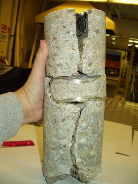


91 Figure C-1. Cores taken from OH 2 (ATH-50). Top: Epoxy-coated dowels; Middle: Stainless steel tubes filled with mortar; Bottom: FRP bars C-1

92 Figure C-2. Epoxy-coated dowels from OH 2 (ATH-50). C-2


93 Figure C-3. Stainless steel tubes from OH 2 (ATH-50). C-3


.")
94 Figure C-4. FRP dowel bars from OH 2 (ATH-50). C-4

95 Figure C-5. Stainless steel clad dowel bars from OH 2 (ATH-50). C-5
96 Load Transfer Efficiency (%) Joint Joint Joint Joint Joint Joint Steel Fiberglass Stainless Steel Dowel Type Load Transfer Efficiency (%) Joint Joint Joint Joint Joint Joint Steel Fiberglass Stainless Steel Dowel Type Figure C and 2004 LTE data for OH 2 (ATH-50). C-6
97 Table C-1. Summary of core retrieval and chloride analysis on OH 2 (ATH-50). Chloride Content Dowel bar material Dowel Deterioration Cty-Rte Direction Pavt Age Core No. Station Dowel Position joint face outside Rust stain in epoxy coating at joint location. Coating easily removed. Bar rusted under O " epoxy coated steel coating I " epoxy coated steel Rust stain in epoxy coating at joint location. Coating easily removed. Bar rusted under coating O " epoxy coated steel none I " epoxy coated steel "bubble" in epoxy coating along dowel axis. Coating easily removed. Bar rusted under bubble O " grout filled stainless steel tube surface of bar has dull appearance I " grout filled stainless steel tube none O " grout filled stainless steel tube rust stain on top of bar at joint face I " grout filled stainless steel tube none O " composite one end of dowel is rough and pitted I " composite one end of dowel is slightly pitted O " composite one end of dowel is rough and pitted I " composite one end of dowel is rough and pitted O " epoxy coated steel epoxy coated damaged near joint face I " epoxy coated steel epoxy coated damaged near joint face O " epoxy coated steel none epoxy coating damaged at joint location. Coating easily removed. Some rust under Coating easily removed. Some rust under " epoxy coated steel coating epoxy coating damaged at joint location * 0.018* " epoxy coated steel coating " epoxy coated steel epoxy coating in excellent condition epoxy coating damaged at joint location. Coating easily removed. Some rust under 0.052* 0.015* " epoxy coated steel coating " stainless steel clad coating in excellent condition with minor corrosion, minor pitting at joint face coating in excellent condition with minor corrosion, minor pitting and small rust stains at 0.089* 0.018* " stainless steel clad joint face " stainless steel clad gap around bar on approach side. coating in excellent condition with minor corrosion, minor pitting at joint face 0.081* 0.032* " stainless steel clad coating in excellent condition with minor corrosion, minor pitting at joint face ATH-50 eastbound westbound all dowels are 1 1/2" diameter stainless steel tube wall thickness is 1/4" C-7
98 Table C-2. Summary of core retrieval and chloride analysis on ALL-81 and SUM-59 (each containing plastic-coated dowels). Dowel Chloride Content Dowel Deterioration Cty-Rte Direction Pavt Age Core No. Station Dowel Position Diameter (in) joint face outside " from EOP 1 1/4 Coating in good condition with one nick and one split. Some minor rust under the split and nick. Remainder of bar in excellent condition " from EOP 1 1/4 Coating on leave side of joint appears to have been damaged during installation or placement of concrete. Some rusting and pitting in damaged areas " from EOP 1 1/4 Coating in good condition with several area where coating had small splits. Some minor rust under the splits " from EOP 1 1/4 Coating in good condition. Some areas on side of bar where coating was abraded and thinned " from EOP 1 1/4 Coating damaged in joint area. Elsewhere, coating in fair condition with areas where coating was abraded and thinned. Rusting and pitting in joint area under coating " from EOP 1 1/4 Coating in good condition. Some rust stains on coating in joint area. Light rust under coat in stained area " from inside EOP 1 1/4 Coating in good condition. Some rust stains on coating in joint area. No rust under coat in stained area " from inside EOP 1 1/4 Coating in good condition. Minor rust stain on coating in joint area. Coating in joint area had minor abrading and thinning " from inside EOP 1 1/4 Coating in good condition. Rust stain and some failure of the coating in joint area. Coating in joint area had minor abrading and thinning. Some rust under coating in stained area " from inside EOP 1 1/4 Coating in good condition except joint area where coating has failed. Rust and some section loss in the joint area " from inside EOP 1 1/4 Coating in good condition. Two locations with minor damage in coating " from inside EOP 1 1/4 Coating in good condition. Two locations with minor damage in coating ALL-81 SUM-59 westbound northbound All bars had a black paste type material, possibly grease or asphalt cement, between the coating and the bar. This material protected the bar from extensive rusting when the coating was split or abraded. Almost all bars had a ridge in the joint area which is probably due to movement of the coating and paste material. Joints were tight. C-8
99 Table C-3. Summary of core retrieval and chloride analysis on older, epoxy-coated dowels in Ohio. Cty-Rte Direction Pavt Age Core No. Station Dowel Position SUM-76 CUY-176 CUY-176 BEL-7 BEL-7 southbound SB eastbound southbound southbound Dowel Diameter (in) C-9 Dowel Deterioration Chloride Content joint face outside wheel path 1 1/2 Rust stain in epoxy coating at joint location. Coating easily removed around stain. Bar pitted under coating wheel path 1 1/2 Bubbles in epoxy coating above "seam" in bar. Coating easily removed. Bar pitted wheel path 1 1/2 None wheel path 1 1/2 Rust stain in epoxy coating at joint location. Coating easily removed around stain. Bar pitted under coating wheel path 1 1/2 none. Epoxy coating damage during removal from core wheel path 1 1/2 None wheel path None 1 1/ wheel path None 1 1/ Epoxy coating damaged in joint area. Bar wheel path 1 1/2 pitted under coating wheel path 1 1/2 none wheel path 1 1/2 none wheel path 1 1/2 None. Epoxy coating not fully bonded to bar wheel path 1 1/2 Rust stain in epoxy coating at joint location. Coating easily removed around stain. Bar pitted under coating /4 Epoxy worn to metal on moving end of dowel. Epoxy easily removed. Rust under the epoxy * 1 1/4 Corrosion visible in areas with deteriorated epoxy coating. Coating easily removed. Rust and pitting over much of the bar under epoxy coating epoxy coating damaged, some possibly due to coring operation. Some epoxy coating easily removed. Areas of rust under epoxy coating * 1 1/ /4 Corrosion visible in areas with deteriorated epoxy coating. Coating easily removed. Rust, pitting and scaling under epoxy in joint area. Some section loss * 1 1/4 Epoxy missing over most of bar. Bar rusty and pitted, with section loss * 1 1/4 Epoxy missing over much of bar. Bar rusty and pitted, with section loss Rust and corrosion in joint area. Epoxy coating easily removed. Some area of the bar pitted and scaling with some section loss / /4 epoxy deteriorated/missing in joint area. Epoxy coating easily removed. Areas of pitting and scaling with some section loss * 1 1/4 none * 1 1/4 epoxy split, steel exposed at joint face. Epoxy easily removed from bar. Bar pitted in joint area. Some section loss /4 epoxy coating split at joint face, some corrosion. Damage to epoxy coating during removal (red circle) Epoxy easily removed, some rust and pitting under epoxy /4 Epoxy coating worn on one end of dowel. Epoxy coating easily removed on this end. Some rust under epoxy /4 epoxy coating split at joint face. Epoxy worn to metal on moving end of dowel. Epoxy easily removed. Rust under the epoxy /4 composite bar, no deterioration /4 epoxy split on one end of dowel, rust stain at the joint face. Epoxy easily removed from that end of dowel. Steel rusted and pitted /4 epoxy split, steel exposed at joint face. Epoxy easily removed from bar. Bar rusted and pitted in area where metal exposed. Some section loss /4 epoxy split, steel exposed at joint face. Epoxy easily removed from bar. Bar rusted and pitted in area where metal exposed
100 Table C-3. Summary of core retrieval and chloride analysis on older, epoxy-coated dowels in Ohio (continued). Cty-Rte Direction Pavt Age Core No. Station Dowel Position MOT-35 CUY westbound northbound Dowel Diameter (in) Dowel Deterioration Chloride Content joint face outside wheel path 1 1/4 epoxy damaged at joint face, damaged area rusted. Coating easily removed around rusted area. Bar pitted under coating wheel path 1 1/4 epoxy damaged at joint face, damaged area rusted wheel path 1 1/4 none wheel path 1 1/4 rust stain in epoxy coating at joint face wheel path 1 1/4 epoxy missing from bottom half of one end of dowel, steel pitted in area of missing epoxy. Some loss of section wheel path 1 1/4 epoxy damaged on one end of dowel " 1 1/4 epoxy in good condition " 1 1/4 Epoxy coating abraded and thinned in joint area. Joint area rusted and pitted " 1 1/4 Epoxy coating abraded and thinned in joint area. Joint area rusted and pitted. Most staining is on exterior of epoxy " 1 1/4 epoxy in good condition. Coating damaged during removal from core " 1 1/4 Epoxy coating abraded and thinned in joint area. Joint area rusted and pitted. Most staining is on exterior of epoxy. Area with ruptured epoxy coating with rust and pitting under Epoxy coating abraded and thinned in joint area. Joint area rusted and pitted. Most " 1 1/4 staining is on exterior of epoxy. Appears to have been a horizontal bar perpendicular to the dowel bar which has totally rusted * Due to joint deterioration, two cores were taken. Material removed from both cores as needed to get sufficient material for testing C-10
101 APPENDIX D ALTERNATIVE DOWEL BAR PROJECT SUMMARIES
102
103 APPENDIX D Alternative Dowel Bar Project Summaries (Note: This appendix contains chapters describing alternative dowel bar projects in Illinois, Iowa, Ohio, and Wisconsin, which were taken directly from the FHWA Report High Performance Concrete Pavements: Summary Report ) CHAPTER 5. ILLINOIS 1 (I-55 SB, Williamsville) Introduction This project was the first constructed by the Illinois Department of Transportation (IDOT) to evaluate alternative dowel bars for use in jointed concrete pavements. Constructed in 1996, the project is located on the exit ramp of a weigh station in the southbound direction of I-55 (milepost 107) near Williamsville, just north of Springfield (see figure 2). Although not a TE-30 project, it did serve as a springboard for future IDOT projects evaluating alternative dowel bars under the TE-30 program Williamsville Springfield 55 Illinois 1 I-55 SB, Williamsville Figure 2. Location of IL 1 project. Study Objectives On most concrete pavements, steel dowel bars are used at transverse joints to provide positive load transfer between adjacent slabs. However, even if epoxy coated, these dowel bars are susceptible to corrosion, which can create locked or frozen joints that can spall and crack the concrete, significantly reducing the service life of the pavement. The purpose of this study, therefore, is to compare the performance of non-corrosive type E fiberglass and polyester dowels to the performance of conventional epoxy-coated dowel bars in a side-by-side field evaluation project. D-1
104 Project Design and Layout This project was constructed in 1996 and consists of a 280-mm (11.25-in) slab placed on a 100- mm (4-in) bituminous aggregate subbase (BAM) (Gawedzinski 2000). In accordance with IDOT practices at the time, the jointed concrete pavement was constructed as a hinge-joint design, in which conventional doweled transverse joints are spaced at 13.7-m (45-ft) intervals and intermediate hinge joints containing tie bars are placed at 4.6-m (15-ft) intervals between the doweled joints (see figure 3); this pavement is essentially a jointed reinforced design with the reinforcing steel concentrated at locations where the pavement is expected to crack. The hinge joints contain number 6 epoxy-coated tie bars, 900-mm (36-in) long and placed at 450-mm (18- in) intervals across the joint (Gawedzinski 2000). Preformed compression seals (32-mm [1.25- in] wide) are placed in the doweled transverse joints and a hot-pour joint seal placed in the tied hinge joints (Gawedzinski 2000). Figure 3. Illinois DOT hinge joint design (IDOT 1989). The pavement was paved 4.9-m (16-ft) wide, and a 3.0-m (10-ft) tied portland cement concrete (PCC) shoulder was placed adjacent to the mainline exit ramp. The shoulders were tied using number 6 epoxy-coated tie bars, 900-mm (36-in) long and placed at 750-mm (30-mm) intervals (Gawedzinski 2000). A total of seven joints (excluding hinge joints) are included in the project, the layout of which is shown in figure 4. The first two regular transverse joints of the project contain conventional epoxy-coated steel dowel bars (38-mm [1.5-in] diameter). The next four regular transverse joints contain type E fiberglass and polyester bars (38-mm [1.5-in] diameter and 450-mm [18-in] long). The fiberglass and polyester resin bars were manufactured by RJD Industries of Laguna Hills, CA. The final regular transverse joint in the project contains conventional epoxy-coated steel dowel bars. D-2
105 From Weigh Station 45 ft Between Contraction Joints } 2 Hinge 15 ft To I-55 SB 16 ft Joint 1 Control Joint 1.5-in Epoxy-Coated Joint in Fiber Composite Dowels Joint in Fiber Composite Dowels Joint 7 Control Joint 1.5-in Epoxy-Coated Dowels Joint 2 Control Joint 1.5-in Epoxy-Coated Dowels Joint in Fiber Composite Dowels Joint in Fiber Composite Dowels Dowels State Monitoring Activities Figure 4. Layout of IL 1 project. IDOT collects traffic data from the sorter scale located at the entrance ramp of the weigh station. Traffic totals from the period from September 1996 to September 1999 are summarized in table 2 (Gawedzinski 2000). Table 2. Traffic data for IL 1 (September 1996 to September 1999) (Gawedzinski 2000). Truck Type Number of Vehicles Accumulated 18-kip ESAL Applications Single-Unit Trucks 95,623 31,324 Multiple Unit Trucks 1,860,542 3,056,458 TOTALS 1,956,165 3,087,783 All seven joints in the project are evaluated at least semi-annually by IDOT to assess their performance. This evaluation consists of both distress surveys and nondestructive testing using the falling weight deflectometer (FWD). Results from the FWD testing program are plotted in figures 5 and 6 (Gawedzinski 2000). Figure 5 shows the load transfer across each of the seven joints as a function of time, whereas figure 6 shows the maximum joint deflection measured at each joint as a function of time. A gradual decrease in overall load transfer efficiency is observed in figure 5, with the conventional steel dowel bars consistently showing higher levels of load transfer then the fiber composite bars. But, as seen in figure 6, the largest deflection is consistently shown by one of the conventional doweled joints, although the other two conventional doweled joints show consistently low deflections. However, for both load transfer types, the load transfer efficiency is still relatively high and the magnitude of the joint deflections relatively low. D-3
106 Figure 5. Load transfer efficiency on IL 1 (Gawedzinski 2000). Figure 6. Maximum joint deflections on IL 1 (Gawedzinski 2000). D-4
107 Preliminary Results/Findings After about 4 years of service, this project is performing well. None of the joints is exhibiting any signs of distress. IDOT will continue monitoring the project to assess the relative performance of the different dowel bar types. Interim Project Status, Results & Findings Truck data continues to be gathered from the sorter scale installed in the entrance ramp of the weigh station. Equivalent Single Axle Loads (ESALs) were computed using scale vendor software and standard IDOT design coefficients. Reported ESAL counts are lower than actual applied ESALs due to the failure of the hard drive on the sorter scale computer for a 13½ month period of time from January 23, 2002 to March 13, ESAL counts for the missing period of time were projected using the truck data previously gathered from the scale and manual counts obtained from scale operators. Cumulative ESAL estimates are provided in table 3 (Gawedzinski 2004). Table 3. Cumulative ESALs as of the Day of FWD Testing (Gawedzinski 2004). Date Cumulative ESALs 09/26/ /18/97 292, /22/97 485, /23/97 1,047, /28/97 1,167, /27/98 1,637, /17/98 2,173, /24/99 2,525, /13/99 2,719, /28/99 3,114, /6/99 3,164, /13/00 3,710, /14/01 5,704, /11/01 6,487, /17/02 7,551, /3/02 8,666, /16/03 9,719, /11/30 9,841, /2/03 10,075, /24/03 10,103,714.9 D-5

108 Visual observations of the joints show no obvious signs of pavement distress; neither faulting nor spalling was evident at any of the seven joints. The original construction had the joints sealed with a preformed elastomeric joint seal material compressed into a 5/8 thick saw cut. Over time, the preformed elastomeric joint material has been pushed deeper into the saw cut, especially in the wheel paths. Load Transfer Efficiency Percentage (LTE %) and joint deflection values were determined for each of the seven pavement joints. The average values were determined from deflections measured as simulated 4, 8, and 12 kip loads were applied to the pavement on the approach and leave sides of the joints. The joints were tested at both inner and outer wheel paths and at the center of the lane for a total of 18 tests per joint. Figure 7 (Gawedzinski 2004) provides a summary of the LTE % versus ESALs, as measured over time. Figure 8 (Gawedzinski 2004) provides a graph of average pavement temperature at a four inch depth verses LTE %. Figure 7. Load Transfer Efficiency vs. ESALs (Gawedzinski 2004). D-6
 Williamsville is the oldest TE-30 test site in Illinois, at 7½ years, and over 10.1 million ESALs.")
109 Figure 8. Load Transfer Efficiency vs. Pavement Temperature (Gawedzinski 2004). Current Observations (Gawedzinski 2004) Williamsville is the oldest TE-30 test site in Illinois, at 7½ years, and over 10.1 million ESALs. The joints at Williamsville show very little sign of distress or damage. The preformed elastomeric joint seal is still intact showing only that it is deeper in the joints under the wheel paths. Overall, only very minor spalling is displayed at the joints; however, it is not known if this was due to damage during the cutting of the original saw cuts or if it has occurred over time. Evaluation of the FWD data indicate that, on average, the fiber composite dowel bars perform somewhat less effectively than the carbon steel control dowel bars. Graphs showing the individual joint performance show that changes in deflection and LTE% are related to the overall pavement system performance, rather than changes in individual joint performance. Dips and spikes in deflection and LTE % are similar to some degree for all of the joints, rather than the joints behaving individually. More frequent FWD testing is planned for the Williamsville site in order to evaluate what causes this response for the bars. Data show LTE% and joint deflection do not appear to be affected by changes in pavement temperature. It is unknown what the moisture content is at the dowel bar/joint interface and how much the moisture content effects LTE% and joint deflections. D-7
110 Points of Contact Mark Gawedzinski Illinois Department of Transportation Bureau of Materials and Physical Research 126 E. Ash Street Springfield, IL (217) David Lippert Illinois Department of Transportation Bureau of Materials and Physical Research 126 E. Ash Street Springfield, IL (217) References Gawedzinski, M TE-30 High Performance Rigid Pavements Illinois Project Review. Illinois Department of Transportation, Springfield, IL. Illinois Department of Transportation (IDOT) Mechanistic Pavement Design. Supplement to Section 7 of the Illinois Department of Transportation Design Manual. Illinois Department of Transportation, Springfield, IL. Gawedzinski, M TE-30 High Performance Rigid Pavements: An Update of Illinois Projects. Illinois Department of Transportation, Springfield, IL. D-8
111 CHAPTER 6. ILLINOIS 2 (Route 59, Naperville) Introduction The first TE-30 project constructed in Illinois is located in the southbound lanes of Illinois Route 59 between 75 th and 79 th Streets, just east of Naperville, a suburb of Chicago (see figure 7). This is IDOT s second project evaluating alternative dowel bar materials, and was constructed in 1997 as part of the reconstruction and widening of Illinois Route 59 (Gawedzinski 2000) Naperville 74 Illinois 2 Route 59, Naperville Springfield 55 Figure 7. Location of IL 2 project. Study Objectives The purpose of this project is to continue IDOT s investigation into alternative dowel bar materials by comparing the performance of IDOT s standard steel dowel bars to several different types of alternative dowel bars (Gawedzinski 2000). This project essentially expands on the IL 1 study by incorporating additional alternative dowel bars from several other manufacturers. Secondary objectives of the study include an evaluation of different transverse joint reservoir designs and a comparison of different traffic counters. Transverse joint reservoir designs include a standard transverse joint configuration containing preformed joint seals, narrow-width joints containing a hot-poured sealant, and narrow-width joints left unsealed. The traffic counters included in the project are conventional loop detectors/piezo electric axle sensors and a new device that measures traffic-induced changes to the earth s magnetic field (Gawedzinski 2000). D-9
112 Project Design and Layout This project was constructed in 1997 and consists of a 255-mm (10-in) slab placed on a 305-mm (12-in) aggregate base course (Gawedzinski 2000). A porous granular embankment subgrade (PGES) material meeting the gradation shown in table 3 is located beneath the aggregate base course (Gawedzinski 1997). Table 3. Gradation of PGES crushed stone material. Sieve Size Percent Passing 150 mm (6 in) mm (4 in) mm (2 in) μm (#200) Pavement designs for the experimental sections consist of both hinge-joint designs and alldoweled designs. As described for IL 1, the hinge-joint design contains conventional doweled transverse joints spaced at 13.7-m (45-ft) intervals and intermediate hinge joints containing tie bars at 4.6-m (15-ft) intervals between the doweled joints (see figure 3). The hinge joints contain number 6 epoxy-coated tie bars, 900-mm (36-in) long and placed at 450-mm (18-in) intervals across the joint. The all-doweled designs have transverse joints spaced at 4.6-m (15-ft) intervals and contain dowel bars across every joint. The project has three lanes in the southbound direction (total width of 10.8-m [36-ft]), with the inside and center lanes paved together and the outside lane paved later. A tied curb and gutter was placed adjacent to both the inside and outside lanes. In addition to pavement design, another variable being evaluated under the study is type of load transfer device. The following five load transfer devices are included (Gawedzinski 1997; Gawedzinski 2000): Conventional 38-mm (1.5-in) diameter epoxy-coated steel dowel bars conforming to ASTM M mm (1.5-in) diameter polyester and type E fiberglass dowel bars, manufactured by RJD Industries. 44-mm (1.75-in) diameter polyester and type E fiberglass dowel bars, manufactured by RJD Industries. 38-mm (1.5-in) diameter polyester and type E fiberglass dowel bars, manufactured by Corrosion Proof Products, Inc. 38-mm (1.5-in) diameter epoxy resin and type E fiberglass dowel bars, manufactured by Glasforms, Inc. Joint width and joint sealant are other variables that are being evaluated under the study. Two of the sections were constructed with 16-mm (0.62-in) wide transverse joints; these were used on the hinge-joint designs only, and were sealed with preformed elastomeric joint seals conforming D-10
113 to AASHTO M220 (Gawedzinski 2000). The other six sections were constructed with narrow 3- mm (0.12-in) transverse joints; five of these were sealed with a hot-poured sealant conforming to ASTM D3405 and one section was left unsealed (Gawedzinski 1997). The layout of the sections is presented in figure 8. This figure summarizes the main features included in each of the sections. The experimental design matrix for this project is shown in table 4. Section 4 All Doweled Joints 1.75-in Fiberglass Dowels (RJD Industries) Narrow Joints Hot-Poured Sealant Section 6 All Doweled Joints 1.5-in Fiberglass Dowels (Glasforms, Inc.) Narrow Joints Hot-Poured Sealant IL Route 59 SB Section 1 Hinge Joint 1.5-in Steel Dowels Wide Joints Preformed Seal Section 2 Hinge Joint 1.5-in Fiberglass Dowels (RJD Industries) Wide Joints Preformed Seal Section 7 All Doweled Joints 1.5-in Steel Dowels Narrow Joints No Joint Sealant Section 8 All Doweled Joints 1.5-in Steel Dowels Narrow Joints Hot-Poured Sealant 270 ft 450 ft 210 ft 225 ft 150 ft 150 ft 450 ft 450 ft Section 3 All Doweled Joints 1.5-in Fiberglass Dowels (RJD Industries) Narrow Joints Hot-Poured Sealant Section 5 All Doweled Joints 1.5-in Fiberglass Dowels (Corrosion Proof Products) Narrow Joints Hot-Poured Sealant Figure 8. Layout of IL 2 project. State Monitoring Activities IDOT collects traffic data for the three southbound lanes and the three northbound lanes using the following devices: Peek 241 traffic classifier. Nu-Metrics Groundhog traffic sensors. The Peek 241 uses traditional traffic loop detectors placed in the subbase, with piezo electric axle sensors installed in channels sawed in the surface of the pavement (Gawedzinski 1997). The Groundhog uses changes in the earth s magnetic field to classify vehicles, and requires only a 178-mm (7-in) diameter hole cored in the new pavement to install the device. However, problems were encountered with the Groundhog device and therefore no comparisons between the devices are possible (Gawedzinski 2000). D-11
114 Table 4. Experimental design matrix for IL 2. Preformed Seal (wide joints) JRCP Hinge-Joint Design 45-ft Joint Spacing Hot-Poured Sealant (narrow joints) No Sealant Preformed Seal (wide joints) JPCP All-Doweled Joints 15-ft Joint Spacing Hot-Poured Sealant (narrow joints) No Sealant 38-mm (1.5-in) Epoxy- Coated Steel Dowel Bars Section 1 (270 ft long, 6 doweled joints) Section 8 (450 ft long, 30 doweled joints) Section 7 (450 ft long, 30 doweled joints) 38-mm (1.5-in) Polyester and Type E Fiberglass Dowel Bars (RJD Industries) Section 2 (450 ft long, 10 doweled joints) Section 3 (210 ft long, 14 doweled joints) 44-mm (1.75-in) Polyester and Type E Fiberglass Dowel Bars (RJD Industries) Section 4 (225 ft long, 15 doweled joints) 38-mm (1.5-in) Polyester and Type E Fiberglass Dowel Bars (Corrosion Proof Products, Inc.) Section 5 (150 ft long, 10 doweled joints) 38-mm (1.5-in) Epoxy- Resin and Type E Fiberglass Dowel Bars (Glasforms, Inc.) Section 6 (150 ft long, 10 doweled joints) Traffic data for the three experimental southbound lanes are summarized in table 5 (Gawedzinski 2000). These data are for the period of September 25, 1997 to January 31, The number of ESALs for each lane was estimated by applying the percentage of vehicles in each lane to the total number of ESALs that were reported for all three traffic lanes (1,515,401). Table 5. Traffic data for IL 2 (September 25, 1997 to January 31, 2000) (Gawedzinski 2000). Project Total Number of Estimated ESALs % of All Vehicles Traffic Lane Vehicles Based on Vehicle % Outside Lane 1 4,687, ,404 Middle Lane 2 6,040, ,668 Center Lane 3 5,689, ,329 TOTALS 16,417, ,515,401 This project is evaluated by IDOT on at least a semi-annual basis. This evaluation consists of both distress surveys and nondestructive testing using the FWD. Results from the FWD testing program are plotted in figures 9 and 10 for sections 1 through 6 only (Gawedzinski 2000). Figure 9 shows the average load transfer for these six test sections as a function of time, whereas figure 10 shows the average maximum joint deflection measured for these six test sections as a function of time. D-12
115 100 Load Transfer Efficiency (%) Aug-97 Apr-97 Oct-98 Mar-99 Oct S1 S2 S3 S4 S5 S6 Test Section Figure 9. Load transfer efficiency on IL 2 (Gawedzinski 2000). Joint Deflection (mils) Aug-97 Apr-97 Oct-98 Mar-99 Oct S1 S2 S3 S4 S5 S6 Test Section Figure 10. Maximum joint deflections on IL 2 (Gawedzinski 2000). D-13
116 The best overall load transfer is exhibited by section 1, which contains the conventional steel dowel bars. The other sections all vary from about 70 to 85 percent, but it is interesting to note how the load transfer fluctuates over time, presumably because of the season and the temperature at the time of testing. Figure 10 shows that the maximum deflections for all joints is increasing over time, with the maximum deflection at the most recent testing (October 1999) significantly larger for all six sections than the previous maximum deflection values. Preliminary Results/Findings After about 3 years of service, this project is performing well. None of the joints is exhibiting any signs of distress. IDOT will continue monitoring the project to assess the relative performance of the different dowel bar types and of the sealed/unsealed joints. One issue for consideration in future installations of fiber composite dowel bars is the method used to secure the bar to the basket. During the construction of the middle and inner lanes of this project, it was noted that the fiber composite bars were loose and only partially attached to the upper support wire of the basket (Gawedzinski 1997). A special metal spring clip provided by RJD Industries was ultimately used to secure the dowel bars to the dowel basket and also to provide an additional frictional force to the bar to prevent it from moving as concrete was placed over the basket (Gawedzinski 1997). Interim Project Status, Results & Findings Traffic data were obtained using preformed loop detectors and piezo sensors placed in each of the three lanes. The detectors and sensors were wired to a Model 241Traffic Classifier produced by Peek Traffic. In August of 2002, the traffic classifier was replaced with a Road Reporter manufactured by International Traffic Corporation/PAT America, Inc. Daily traffic files are polled periodically and tabulated to provide monthly traffic totals for classification. Standard conversion factors used by the Illinois Department of Transportation are used to convert Single Unit (SU) and Multiple Unit (MU) truck counts to ESALs. In May of 2003, land development work on the properties on the east side of IL 59 resulted in an east-west access road intersecting IL 59 at the location of the traffic classifier loops and piezo sensors. Traffic signals associated with the new road necessitated relocating the traffic classifier site approximately 0.4 miles to the south. Work on relocating the site will be complete in Cumulative ESAL information for each lane, as reported by the Illinois Department of Transportation (Gawedzinski 2004) are provided in table 6. FWD tests are currently performed annually across all of the test sections. Certain sections were dropped from the FWD testing for a period of time due to traffic safety issues. These issues were resolved and now FWD results are obtained for both wheel paths and the center of the lane for all three lanes. Visual observations of joint performance are performed periodically, noting any changes in the appearance of the pavement. Results of the FWD tests are provided in figures 11 through 13 for the right, center and left lanes respectively. D-14

117 Table 6. Traffic data for IL 2 (September 25, 1997 to June 16, 2003) (Gawedzinski 2004). Date Cumulative ESALs Right Lane Center Lane Left Lane 8/25/97 1,751 4,288 1,008 4/6/98 73, ,779 33,118 10/19/98 160, ,559 71,363 3/29/99 210, ,343 95,277 10/13/99 319, , ,165 4/24/00 393, , ,867 10/16/00 480, , ,076 5/15/01 560, , ,037 5/1/02 661,433 1,110, ,719 6/16/03 728,208 1,249, ,084 Figure 11. Load Transfer Efficiency vs. ESALs for the Right Lane (Gawedzinski 2004). D-15


118 Figure 12. Load Transfer Efficiency vs. ESALs for the Center Lane (Gawedzinski 2004). Figure 13. Load Transfer Efficiency vs. ESALs for the Left Lane (Gawedzinski 2004). D-16
 material is acting more as joint filler in that there are areas across several joints where the")
119 Current Observations (Gawedzinski 2004) Evaluation of the joints shows typical behavior of the joints and the joint sealer/filler material with no obvious signs of spalling or faulting. The preformed elastomeric joint sealer remains intact, while the ASTM D-6690 (formerly ASTM D-3405) material is acting more as joint filler in that there are areas across several joints where the material has become debonded from the pavement, allowing water and incompressibles into the joint. Observations of the LTE% vs. time and ESALs graphs, as well as the joint deflection vs. time and ESALs graphs, show somewhat consistent behavior for joint deflection, with sections averaging between 3 to 5 mils. LTE% graphs show behavior consistent with a decrease in joint deflection. Figure 14 shows the same type of behavior displayed at the Williamsville, IL test site (Illinois 1). Plots of average values show no relationship between LTE% or joint deflection and average pavement temperature. The control bars (1½ Ø epoxy coated carbon steel) have a higher LTE% and lower joint deflection than any of the fiber composites, but the overall performance of the fiber composite bars appears to be very close to the behavior of the epoxy coated steel control set. Figure 14. Average Load Transfer Efficiency vs. Pavement Temperature for all Lanes (Gawedzinski 2004). D-17
120 Points of Contact Mark Gawedzinski Illinois Department of Transportation Bureau of Materials and Physical Research 126 E. Ash Street Springfield, IL (217) David Lippert Illinois Department of Transportation Bureau of Materials and Physical Research 126 E. Ash Street Springfield, IL (217) References Gawedzinski, M Fiber Composite Dowel Bar Experimental Feature Construction Report. Illinois Department of Transportation, Springfield, IL. Gawedzinski, M TE-30 High Performance Rigid Pavements Illinois Project Review. Illinois Department of Transportation, Springfield, IL. Gawedzinski, M TE-30 High Performance Concrete Pavements: An Update of Illinois Projects. Illinois Department of Transportation, Springfield, IL. D-18
121 CHAPTER 7. ILLINOIS 3 (U.S. Route 67, Jacksonville) Introduction IDOT s second TE-30 project, and their third evaluating alternative dowel bar materials, is located on the two westbound lanes of U.S. Route 67, west of Jacksonville (see figure 11). This project was constructed in Illinois 3 U.S. 67 WB, Jacksonville Jacksonville Springfield 55 Figure 11. Location of IL 3 project. Study Objectives This project continues IDOT s investigation of alternative dowel bar materials and joint sealing effectiveness (Gawedzinski 2000). Several additional fiber composite dowel bars are evaluated in this study that were not included in previous studies, and these comparisons are all done using IDOT s now standard all-doweled jointed plain concrete pavement (JPCP) design. In addition, an unsealed section is included to further investigate the performance of unsealed joints. Project Design and Layout Constructed in 1999, the basic pavement design for each section is a 250-mm (10-in) thick JPCP placed on a 100-mm (4-in) cement aggregate mixture (CAM) base course (Gawedzinski 2000). The existing subgrade was stabilized to a depth of 300 mm (11.8 in) with lime (Gawedzinski 2000). Transverse joints are spaced at 4.6-m (15-ft) intervals and tied concrete shoulders are incorporated as part of the construction project. The project consists of seven test sections evaluating alternative dowel bar materials and unsealed joints. The following load transfer devices are included in the study (Gawedzinski 2000): D-19
122 38-mm (1.5-in) diameter polyester and type E fiberglass dowel bars, manufactured by RJD Industries. 38-mm (1.5-in) diameter vinyl ester and type E fiberglass dowel bars, manufactured by Strongwell (Morrison Molded Fiber Glass Company). 38-mm (1.5-in) diameter vinyl ester and type E fiberglass dowel bars, manufactured by Creative Pultrusions, Inc. Fiber-Con dowel bar, manufactured by Concrete Systems, Inc. and consisting of a fibrillated type E fiberglass and polyester resin tube filled with hydraulic cement. 38-mm (1.5-in) diameter carbon steel rods clad with grade 316 stainless steel, manufactured by Stelax Industries Inc. Conventional 38-mm (1.5-in) diameter epoxy-coated steel dowel bars conforming to ASTM M227. All but one of the sections was sealed with a hot-poured joint sealant conforming to ASTM D One section was left unsealed to compare the performance of pavements with unsealed joints to that of sealed joints. The layout of the sections is presented in figure 12. This figure summarizes the main features included in each of the sections. The experimental design matrix for this project is shown in table 6. U.S. 67 WB Section in Fiberglass Dowel Bars (RJD Industries) Sealed Joints Section in Fiberglass Dowel Bars (Morrison Molded Fiber Glass Co.) Sealed Joints Section in Fiberglass Dowel Bars (Creative Pultrusions, Inc.) Sealed Joints Section 4 Fiberglass Tubes Filled with Cement (Concrete Systems, Inc.) Sealed Joints Section in Stainless Steel Clad Dowel Bars (Stelax Industries Ltd.) Sealed Joints Section in Epoxy-Coated Steel Dowel Bars Unsealed Joints Section in Epoxy-Coated Steel Dowel Bars Sealed Joints 150 ft 150 ft 165 ft 150 ft 150 ft 150 ft 150 ft Figure 12. Layout of IL 3 project. D-20
123 State Monitoring Activities IDOT installed an automatic traffic recording station at the project site in February Traffic data are recorded using a Peek series 3000 ADR traffic classifier (Gawedzinski 2000). No traffic data are currently available. Table 6. Experimental design matrix for IL mm (1.5-in) diameter polyester and type E fiberglass dowel bars (RJD Industries) 38-mm (1.5-in) diameter vinyl ester and type E fiberglass dowel bars (Morrison Molded Fiber Glass Company) 38-mm (1.5-in) diameter vinyl ester and type E fiberglass dowel bars (Creative Pultrusions, Inc.) Fiber-Con dowel bar, consisting of a fibrillated type E fiberglass and polyester resin tube filled with hydraulic cement (Concrete Systems, Inc.) 38-mm (1.5-in) diameter carbon steel rods clad with grade 316 stainless steel (Stelax Industries Inc.) 38-mm (1.5-in) diameter epoxy-coated steel dowel bars 250-mm (10-in) JPCP 4.6-m (15-ft) Joint Spacing Sealed Joints Unsealed Joints (ASTM D3405) Section 1 (150 ft long, 10 joints) Section 2 (150 ft long, 10 joints) Section 3 (150 ft long, 11 joints) Section 4 (150 ft long, 10 joints) Section 5 (150 ft long, 10 joints) Section 7 (150 ft long, 10 joints) Section 6 (150 ft long, 10 joints) Before the pavement was opened to traffic, IDOT conducted FWD testing on the experimental sections in June Results from the FWD testing program are plotted in figures 13 and 14 (Gawedzinski 2000). Figure 13 shows the average load transfer for the seven experimental sections in both the driving and passing lanes, whereas figure 14 shows the average maximum joint deflection measured for each of the seven experimental sections in both the driving and passing lanes. Although the joint deflections are low, the load transfer efficiencies are not as high as might be expected for a new concrete pavement. These initial FWD results will serve as a baseline for comparison with future testing values. D-21


124 Figure 13. Load transfer efficiency on IL 3 (Gawedzinski 2000). Figure 14. Maximum joint deflections on IL 3 (Gawedzinski 2000). D-22
125 Preliminary Results/Findings This pavement is performing well after 1 year of service. None of the joints are exhibiting any signs of distress. IDOT will continue monitoring the project to assess the relative performance of the different dowel bar types and of the sealed/unsealed joints. Interim Project Status, Results & Findings FWD tests are conducted semi-annually along with periodic visual observations of joint performance. Traffic data is collected using an ADR 3000, manufactured by Peek Traffic. The data is periodically polled and converted to ESALs using standard IDOT conversion factors. A summary of the cumulative ESALs is provided in table 7. Joints are also periodically observed, to look for signs of joint deterioration or distress. Joints were formed using a thin saw cut and sealed with an ASTM D 6690 (formerly ASTM D 3405) hot pour joint seal material. Problems affecting ride quality became apparent, due to several of the joints being overfilled with the 3405 joint seal material. Subsequent evaluations noted failure of the 3405 joint seal material to maintain a bond with either side of the pavement at the joint. Table 7. Current Traffic for Driving and Passing Lanes (Gawedzinski 2004). Date Cumulative ESALs Driving Lane Passing Lane 6/23/ /27/00 68,604 9, /10/00 95,413 13,764 4/18/01 160,805 22,940 10/11/01 240,558 34,305 4/18/02 310,034 43,193 10/01/02 372,800 48,871 4/16/03 442,221 54,892 10/21/03 493,053 59,488 11/25/03 504,163 Current Observations (Gawedzinski 2004) Several joints were observed where the joint seal material was either missing from the wheel paths, or had been pushed deeper in the joint and was debonded from both sides of the pavement joint. A large amount of small rocks were also compressed into the joint seal material at the joint surface. As with the other sites (IL 1 & IL 2), no obvious signs of joint distress were apparent during the visual observations. Similar behavior as observed at the older two sites (IL 1 & IL2) is shown in the following figures. The control set (1½ Ø epoxy coated steel), unsealed epoxy coated steel bars, stainless steel clad carbon steel bars, and fibrillated wound fiber composite bars exhibit better LTE and D-23
 was constructed on a cement aggregate mixture subbase (CAM2 w/ a minimum of 200 lbs of cement per cubic yard) rather than a granular subbase as in Naperville (IL 2) or")
126 lower joint deflections than the pultruded fiber composite bars, but do not show excessive joint deflection indicating failure of the joints. Pavement at Jacksonville (IL 3) was constructed on a cement aggregate mixture subbase (CAM2 w/ a minimum of 200 lbs of cement per cubic yard) rather than a granular subbase as in Naperville (IL 2) or a bituminous aggregate mixture subbase (BAM) at Williamsville (IL 1). An additional FWD test was performed on the driving lane of US 67 in November of 2003 to evaluate the joint deflections which had occurred earlier that year. Testing was not conducted in the passing lanes due to traffic control problems at the time of the November tests. The large shift in average joint deflection vales between the April and October tests necessitated the November retest. More frequent testing is scheduled for Figure 15. Driving Lane Load Transfer Efficiency vs. ESALs (Gawedzinski 2004). D-24


127 Figure 16. Passing Lane Load Transfer Efficiency vs. ESALs (Gawedzinski 2004). Figure 17. Average Load Transfer Efficiency vs. Average Pavement Temperature (Gawedzinski 2004). D-25
128 Points of Contact Mark Gawedzinski Illinois Department of Transportation Bureau of Materials and Physical Research 126 E. Ash Street Springfield, IL (217) David Lippert Illinois Department of Transportation Bureau of Materials and Physical Research 126 E. Ash Street Springfield, IL (217) Reference Gawedzinski, M TE-30 High Performance Rigid Pavements Illinois Project Review. Illinois Department of Transportation, Springfield, IL. Gawedzinski, M TE-30 High Performance Concrete Pavements: An Update of Illinois Projects. Illinois Department of Transportation, Springfield, IL. D-26
129 CHAPTER 8. ILLINOIS 4 (Route 2, Dixon) Introduction A fourth project evaluating alternative dowel bars was constructed by IDOT in the April The experimental project is located in the driving lane of the northbound direction of Illinois Route 2 in Dixon (see figure 15) where it replaces an existing concrete pavement (Gawedzinski 2000) Dixon 74 Illinois 4 Route 2 NB, Dixon 72 Springfield 55 Figure 15. Location of IL 4 project. Study Objectives Although not an official TE-30 project, this project carries on IDOT s investigation of alternative dowel bar materials. The alternative dowel bar materials used in the project included stainless steel tubes filled with cement grout, stainless steel clad carbon steel tubes, and fiber composite tubes filled with cement grout. Two different diameters, 38-mm (1.5 in) and 44.5-mm (1.75 in), were used for the stainless steel tubes and for the stainless steel clad dowels. The fiber composite tubes were formed using a pultrusion process and were approximately 50-mm (2 in) in diameter. The pultrusion process produced a much smoother bar, compared to the first generation, fibrillated bars. Additionally two different methods of securing the bars to the baskets, welding and using cable ties, were used in the four sections. Additional construction details are presented in the literature. D-27
130 Project Design and Layout The pavement design for each section is a 240-mm (9.5-in) doweled JPCP placed over a 300-mm (12-in) granular base course (Gawedzinski 2000). Transverse joints are spaced at 4.6-m (15-ft) intervals and are sealed with a hot-poured sealant. A tied curb and gutter is placed adjacent to the outer driving lane of the project. The experimental project consists of five test sections evaluating the following alternative dowel bar materials (Gawedzinski 2000): Fiber-Con dowel bar, manufactured by Concrete Systems, Inc. and consisting of a pultruded fiber composite tube composed of type E fiberglass and polyester resin and filled with hydraulic cement. 38-mm (1.5-in) diameter, 2.76 mm (0.109 in) thick grade 316 stainless steel tube filled with cement grout mm (1.75-in) diameter, 2.76 mm (0.109 in) thick grade 316 stainless steel tube filled with cement grout. 38-mm (1.5-in) diameter carbon steel rods clad with grade 316 stainless steel, manufactured by Stelax Industries Inc mm (1.75-in) diameter carbon steel rods clad with grade 316 stainless steel, manufactured by Stelax Industries Inc. Conventional load transfer devices are installed in JPCP sections adjacent to the experimental pavement sections. State Monitoring Activities Traffic data will be recorded using a Peek series 3000 ADR traffic classifier. IDOT obtained baseline FWD deflection data after the pavement was constructed and will monitor its performance on at least a semi-annual basis. Interim Project Status, Results & Findings Data has been collected on a semi-annual basis for the past three years. The cumulative ESALs are provided in table 12. Results of deflection testing are illustrated in the following figures. Table 12. Data Collection Date and Cumulative ESALs (Gawedzinski 2004). Date Cumulative ESALs 8/1/00 0 5/1/01 20,780 10/1/01 50,036 4/25/02 62,701 10/2/02 76,872 4/3/03 93,982 10/3/03 125,533 D-28


131 Figure 16. Driving Lane Load Transfer Efficiency vs. ESALs (Gawedzinski 2004). Figure 17. Average Load Transfer Efficiency vs. Average Pavement Temperature (Gawedzinski 2004). D-29
132 Current Observations (Gawedzinski 2004) At the time of construction, all of the test joints were to remain unsealed. Visual observation of the joints show all of the joints performing well with slight spalling possibly due to the pavement being cut too early. None of the joints show accumulation of incompressible material in the joint or any significant spalling due to the joints locking up. Additional monitoring will continue. The LTE% and joint deflection graphs show behavior expected with relatively new pavements. Points of Contact Mark Gawedzinski Illinois Department of Transportation Bureau of Materials and Physical Research 126 E. Ash Street Springfield, IL (217) David Lippert Illinois Department of Transportation Bureau of Materials and Physical Research 126 E. Ash Street Springfield, IL (217) References Gawedzinski, M TE-30 High Performance Rigid Pavements Illinois Project Review. Illinois Department of Transportation, Springfield, IL. Gawedzinski, M TE-30 High Performance Concrete Pavements: An Update of Illinois Projects. Illinois Department of Transportation, Springfield, IL. D-30
133 CHAPTER 11. IOWA 2 (U.S. Route 65, Des Moines) Introduction The Iowa Department of Transportation s second TE-30 project consists of an evaluation of alternative dowel bar materials and spacings. The experimental project was constructed in 1997 on the U.S. 65 Bypass near Des Moines (Cable and McDaniel 1998b). Figure 17 shows the location of this project. 35 Des Moines Iowa 2 U.S. 65 Bypass, Des Moines Figure 17. Location of IA 2 project. Study Objectives Because of the susceptibility of steel dowel bars to corrosion, the Iowa DOT has expressed interest in the use of alternative dowel bar materials to provide load transfer across transverse joints in concrete pavements. Therefore, one of the goals of this project is the comparative study of concrete pavement joints containing fiber reinforced polymer (FRP) dowel bars, stainless steel dowel bars, and conventional epoxy-coated steel dowel bars under the same design criteria and field conditions (Cable and McDaniel 1998b). Another goal of the project is the investigation of the transverse joint load transfer characteristics of alternative dowel bar spacings (Cable and McDaniel 1998b). This evaluation is a 5-year study being performed through the combined efforts of the Iowa Department of Transportation and the Iowa State University. Project Design and Layout This project was constructed in 1997 on the northbound lanes of the U.S. 65 Bypass near Des Moines. The basic design for the project is a 305-mm (12-in) JPCP on a 152-mm (6-in) granular base course (Cable and McDaniel 1998b). Transverse joints are located at 6.1-m (20-ft) intervals D-31
134 and are skewed 6:1 in the counterclockwise direction (Cable and McDaniel 1998b). Both transverse and longitudinal joints are sealed with a hot-poured sealant. Number 5 tie bars, 914 mm (36 in) long and spaced at 762-mm (30-in) intervals, were mechanically inserted by the paver across the longitudinal centerline joint (Cable and McDaniel 1998b). The shoulder for the JPCP is a 203-mm (8-in) asphalt concrete (AC) layer, paved 2.4 m (8 ft) wide on the outside edge and 1.6 m (6 ft) on the inside edge (Cable and McDaniel 1998b). Longitudinal subdrains are located under the outside shoulder and adjacent to the edge of the outside driving lane (Cable and McDaniel 1998b). Four different load transfer systems are included in the study: a fiber composite dowel bar manufactured by Hughes Brothers, a fiber composite dowel bar manufactured by RJD Industries, a Type 316L solid stainless steel dowel bar, and a conventional epoxy-coated steel dowel bar (Cable and McDaniel 1998b). The Hughes Brothers dowel bar is 48 mm (1.88 in) in diameter, whereas the other dowel bars are 38 mm (1.5 in) in diameter. The required diameters for the alternative dowel bars were determined from laboratory testing and experimental research performed by the manufacturers (Cable and McDaniel 1998b). A standard spacing of 305 mm (12 in) was used for each load transfer system included in the study. In addition, sections were constructed using a spacing of 203 mm (8 in) for the alternative dowel bar materials. The experimental design matrix for this project is shown in table 9, and the layout of the test sections is shown in figure 18. The dowel bar spacing configurations used on this project are illustrated in figure 19. Table 9. Experimental design matrix for IA mm (12-in) JPCP 6.1-m (20-ft) Joint Spacing (skewed) Fiber Composite Dowel Bars (Hughes Brothers) Fiber Composite Dowel Bars (RJD Industries) Stainless Steel Dowel Bars Epoxy-Coated Steel Dowel Bars 38-mm (1.5-in) Diameter Dowel Section 3 (100 ft) Section 5 (222 ft) 203-mm (8-in) Dowel Spacing 48-mm (1.88-in) Diameter Dowel Section 1 (440 ft) 38-mm (1.5-in) Diameter Dowel Section 4 (80 ft) Section 6 (556 ft) Section 8 (477 ft) 305-mm (12-in) Dowel Spacing 48-mm (1.88-in) Diameter Dowel Section 2 (417 ft) D-32
135 Section in Fiber Composite Dowel Bars (RJD Industries) 8 in Dowel Spacing Section in Fiber Composite Dowel Bars (RJD Industries) 12 in Dowel Spacing U.S. 65 NB Section in Fiber Composite Dowel Bars (Hughes Brothers) 8 in Dowel Spacing Section in Fiber Composite Dowel Bars (Hughes Brothers) 12 in Dowel Spacing Section in Stainless Steel Dowel Bars 8 in Dowel Spacing Section in Stainless Steel Dowel Bars 12 in Dowel Spacing Section in Epoxy-Coated Steel Dowel Bars 12 in Dowel Spacing 440 ft 417 ft 100 ft 80 ft 222 ft 556 ft 477 ft Figure 18. Layout of IA 2 project. Outer Traffic Lane Inner Traffic Lane in spacings in spacings a) 12-in Spacings Inner Traffic Lane Outer Traffic Lane 18 8-in spacings 18 8-in spacings b) 8-in Spacings Figure 19. Illustration of dowel bar spacing configurations on IA 2. D-33
136 Fiber composite tie bars were also provided by the fiber composite dowel bar manufacturers for installation in their respective test sections. However, these fiber composite tie bars had a tendency to float to the top of the surface during or immediately after their placement (Cable and McDaniel 1998b). This was attributed to either an incompatibility of the automatic tie bar inserter to the smaller diameter of the fiber composite tie bars or to the lighter weight of the fiber composite bars themselves (Cable and McDaniel 1998b). After several bars surfaced in succession, the epoxy-coated steel tie bars were used on the remainder of the project. State Monitoring Activities The performance of these test sections was monitored under a 5-year monitoring program (from the Fall of 1997 through the Spring of 2003) being conducted jointly by the Iowa DOT and the Iowa State University (Cable and Porter 2003). The following monitoring activities were conducted (Cable and Porter 2003): Visual distress survey using LTPP procedures. As part of these surveys, joint openings were monitored using PK nails placed along joints in each section, and joint faulting was measured using a Georgia Digital Faultmeter. Deflection testing using a Dynatest Falling Weight Deflectometer (FWD). Within each section, deflection testing was performed at three joints and at three center slab locations per lane. Testing was performed twice a year, once in March or April (to represent a weak foundation condition) and once in August or September (to represent a strong foundation condition). In addition, ground penetrating radar (GPR) was used to establish the location (depth and orientation) of dowel bars and tie bars (Cable and Porter 2003). At the end of 5 years, selected joints in each section were cored and the condition of each dowel bar type was inspected (Cable and Porter 2003). Preliminary Results/Findings During the construction of the project, several items were noted to be of importance to future installations of alternative dowel bars in concrete pavements (Cable and McDaniel 1998b): The original method of securing the fiber composite and stainless steel dowel bars to the basket was inadequate. To address this, plastic zip ties were fastened around each basket brace loop and end of dowel to hold them in place. Any excess tie length was cut or turned down to prevent surface finishing problems. The placement of the stainless steel dowels required three to five people to handle the baskets. Future use of stainless steel dowels will require x braces welded to the basket to prevent side sway and collapse during handling. Nails were attached to the bottom of the fiber composite tie bars to facilitate their location using both cover meters and GPR. As stated previously, the fiber composite tie bars, placed using the automatic tie bar inserter on the paver, were susceptible to floating to the surface. If this is a continuing problem, the placement of these bars in tie bar baskets or the use of conventional epoxycoated tie bars may be required. D-34
.")
137 Final Results/Findings Project test sections were tested twice a year, beginning in the Fall of 1997, with the final tests in the Spring of Testing could not be performed in the fall of The results of the FWD testing were interpreted through calculating load transfer efficiency. The results of the load transfer analysis are illustrated in figure 20 (Cable and Porter 2003). In figure 20, the dowel bars are labeled according to their material and spacing: standard epoxy (std. epoxy), stainless steel (S.S.), fiber composite (FRP). Figure 21 displays the overall average faulting over the period of research (Cable and Porter 2003). Figure 22 illustrates the changes in joint openings over the research period (Cable and Porter 2003). Visual surveys of this project resulted in only minor corner cracking being noted immediately after construction. There are no visible signs of pavement distress that can be associated with joint reinforcement or typical highway loading over the five years of surveys (Cable and Porter 2003). The following summaries and conclusions have been reached based on the data gathered during the study (Cable and Porter 2003): All dowel materials tested are performing equally in terms of load transfer, joint movement, and faulting over the five-year analysis period. Stainless steel dowels do provide load transfer performance equal to or greater than epoxy-coated steel dowels in this study on the average over five years. FRP dowels of the sizes tested in this research should be spaced no greater than 8 inches (203 mm) apart to gain load transfer performance at the same level as epoxy-coated steel dowels at 12-inch (305 mm) spacing. No deterioration due to road deicers was found on any of the dowel materials retrieved in the 2002 coring operation. Figure 20. Average Load Transfer Efficiency. D-35
138 0 8" 1.5" 12" 1.5" 8" 1.88" 12" 1.88" 8" Ave. Fault, in Outside Wheelpath Ave. Inside Wheelpath Ave. Average Figure 21. Average Faulting Over Research Period Joint Opening Change (mm) Fall 1997 Spring 1998 Fall 1998 Spring 1999 Fall 1999 Spring 2000 Data Collection Period Spring 2001 Fall 2001 Spring 2002 Epoxy@12" SS@12" SS@8" 1.5"FRP@12" 1.5"FRP@8" 1.88"FRP@12" 1.88"FRP@8" Figure 22. Joint Opening Trends. D-36
139 Points of Contact Jim Cable Iowa State University Department of Civil and Construction Engineering 378 Town Engineering Building Ames, IA (515) Mark Dunn Iowa Department of Transportation 800 Lincoln Way Ames, IA (515) Reference Cable, J. K. and L. L. McDaniel. 1998b. Demonstration and Field Evaluation of Alternative Portland Cement Concrete Pavement Reinforcement Materials. Iowa DOT Project HR Iowa Department of Transportation, Ames, IA. Cable, J. K. and M. L. Porter Demonstration and Field Evaluation of Alternative Portland Cement Concrete Pavement Reinforcement Materials. Iowa DOT Project HR Iowa State University, Ames, IA. D-37
140 CHAPTER 27. OHIO 1, 2, AND 3 (U.S. Route 50, Athens) Introduction Under the TE-30 program, the Ohio Department of Transportation (ODOT) constructed three experimental pavement projects on U.S. 50, approximately 8 km (5 mi) east of the city of Athens (see figure 45). The projects incorporate a variety of experimental design features, including high-performance concrete mixtures utilizing ground granulated blast furnace slag (GGBFS) (Ohio 1), alternative dowel bar materials (Ohio 2), and alternative joint sealing materials (Ohio 3) (Ioannides et al. 1999; Sargand 2000; Hawkins et al. 2000). Although each project was funded separately under the TE-30 program, they are all located on the same section of roadway and share many of the same design and construction attributes, as well as the same traffic and environmental loadings; therefore, these projects are all described together in this chapter Columbus Athens Ohio 1, 2, and 3 U.S. 50, Athens Figure 45. Location of OH 1, 2, and 3 projects. D-38
141 Study Objectives The study objectives for the overall U.S. 50 pavement project may be broken out by each specific study. For OH 1, the evaluation of GGBFS, the primary objective is to evaluate the effectiveness of GGBFS as a partial cement replacement in PCC pavements. The expectation of adding GGBFS to a concrete mix is increased workability, increased durability, and increased long-term strength. For OH 2, the evaluation of alternative dowel bar materials, the general purposes of the study are to evaluate dowel response under a variety of loading and environmental conditions and to compare the measured responses of different types of dowel bars (Sargand 2000). Specific objectives include the following (Sargand 2000): Instrument standard steel and fiberglass dowels for the monitoring of strain induced by curing, changing environmental conditions, and applied dynamic forces. Record strain measurements periodically over time to determine forces induced in the dowel bars during curing and during changing environmental conditions. Record strain measurements in the dowel bars as dynamic loads are applied with the FWD. Evaluate strain histories recorded for the in-service pavement. For OH 3, the evaluation of joint sealing materials, the objectives are to (Ioannides et al. 1999): Assess the effectiveness of a variety of joint sealing practices employed after the initial sawing of joints, and to examine their repercussions in terms of reduced construction times and life-cycle costs. Identify those materials and procedures that are most cost effective. Determine the effect of joint sealing techniques on pavement performance. Project Design and Layout General Design Information The U.S. 50 project is a 10.5-km (6.5-mi) segment of highway that was reconstructed and expanded to a new four-lane divided facility. The eastbound lanes of the project were constructed in the fall of 1997, and the westbound lanes were constructed in the fall of 1998 (Ioannides et al. 1999). The 20-year design traffic loading for this pavement is approximately 11 million ESAL applications. The subgrade over the project site is predominantly a silty clay material (Ioannides et al. 1999). The cross-sectional design for the projects is a 254-mm (10-in) JRCP placed over a 102-mm (4- in) open-graded base course. The open-graded base course in the eastbound direction is a New Jersey type nonstabilized base, whereas the open-graded base course in the westbound direction is a Iowa type nonstabilized base (Ioannides et al. 1999). A 152-mm (6-in) crushed aggregate D-39
142 subbase is located beneath the open-graded bases, and is topped with a bituminous prime coat to prevent migration of fines into the open-graded layers (Ioannides et al. 1999). Table 21 provides the actual project gradations for these materials. A 102-mm (4-in) underdrain was placed at both the outside and inside edges of the pavement to collect infiltrated moisture from the open-graded bases (Ioannides et al. 1999). Table 21. Comparison of actual base and subbase gradations used on Ohio U.S. 50 project. Total Percent Passing Sieve New Jersey Open- Iowa Open- Crushed Aggregate Size Graded Base (EB) Graded Base (WB) Subbase (EB/WB) 2 in 100 1½ in in 100 # # # # # # # The slabs are reinforced with smooth welded wire fabric (WWF) to control random cracking (Sargand 2000). Wire style designation W8.5 x W4 6x12 was specified, meaning that the longitudinal wires have a cross sectional area of 54.8 mm 2 (0.085 in 2 ) and are spaced 152 mm (6 in) apart, and the transverse wires have a cross-sectional area of 25.8 mm 2 (0.04 in 2 ) and are spaced 305 mm (12 in) apart. This style designation translates to a longitudinal steel content of 0.14 percent. The transverse joints are spaced at fixed 6.4-m (21-ft) intervals and contain 38-mm (1.5-in) diameter, 457-mm (18-in) long, epoxy-coated dowel bars on 305-mm (12-in) centers (Sargand 2000). However, some of the joints within the alternative dowel bar project contain either fiberglass dowels or stainless steel tubes filled with concrete (Sargand 2000). Transverse joints were sealed with a preformed compression sealant except for the joints within the joint sealant project. The longitudinal centerline joint is tied with 16-mm (0.62-in) diameter, 760-mm (30-in) long, deformed bars spaced at 760-mm (30-in) intervals (Ioannides et al. 1999). Plain concrete shoulders were paved separately from the mainline pavement. These were tied to the mainline pavement using 16-mm (0.62-in) diameter, 76-mm (30-in) long, deformed tie bars. The outside shoulder is 3 m (10 ft) wide and the inside shoulder is 1.2 m (4 ft) wide (Ioannides 1999). Project Layout Information As described previously, the U.S. 50 project actually includes three projects, one evaluating GGBFS, one evaluating alternative dowel bar materials, and one evaluating joint sealant materials. In addition, a control section that does not contain GGBFS is located at the western D-40
143 end of the project. The general layout of these projects is shown in figure 46. More detailed information on each project is provided in the following sections. Begin Project STA End Project STA OH 3 Joint Seal Study to OH 3 Joint Seal Study to U.S. 50 WB U.S. 50 EB OH 2 Dowel Bar Study to OH 3 Joint Seal Study to OH 3 Joint Seal Study to OH 1 Control Section (No GGBFS in mix) to OH 1 GGBFS Study to Both Directions Figure 46. Layout of experimental projects on Ohio U.S. 50. OH 1, Evaluation of Ground Granulated Blast Furnace Slag The entire 10.5-km (6.5-mi) length of the U.S. 50 project was constructed using a highperformance concrete mix. The mixture consists of a Type I cement with GGBFS replacing 25 percent of the cement (Sargand 2000). An AASHTO #8 gravel (0.13 mm [0.5 in] top size) was used for the coarse aggregate and a natural sand was used for the fine aggregate (Sargand 2000). A w/c of 0.44 was used in the mix design. The complete PCC mix design is shown in table 22. Table 22. Concrete pavement mix design used on Ohio U.S. 50 project. PCC Mix Design Component Quantity Natural Sand 1437 lb/yd 3 AASHTO #8 Aggregate 1374 lb/yd 3 Type I Cement 412 lb/yd 3 Water 236 lb/yd 3 GGBFS 138 lb/yd 3 Water Reducer 11 oz/yd 3 Air Entraining Agent 16.5 oz/yd 3 Design Air 8% Design Slump 3 in D-41
144 Samples from the concrete mix used in the actual paving operation were tested in the laboratory and showed a 28-day compressive strength of 27.6 MPa (4000 lbf/in 2 ) and a 28-day modulus of rupture of 2.76 MPa (400 lbf/in 2 ) (Sargand 2000). The 28-day static modulus of elasticity was GPa (3,760,000 lbf/in 2 ) (Sargand 2000). As previously mentioned, a control pavement section that does not contain GGBFS in the concrete mix is located at the western end of the project, between stations and Other than the mix design, the design of the control section is the same as the GGBFS section. OH 2, Evaluation of Alternative Dowel Bars Three types of dowel bars were used in the dowel bar project: epoxy-coated steel dowel bars, fiberglass dowel bars (manufactured by RJD Industries, Inc.), and stainless steel tubes filled with concrete. The diameter of the steel and fiberglass dowels bars is 38 mm (1.5 in), while the stainless steel tubes have an outer diameter of 38 mm (1.5 in) and an inner diameter of 34 mm (1.35 in) (Sargand 2000). All bars are 457 mm (18 in) long. Most of the U.S. 50 project contains conventional epoxy-coated steel dowel bars. However, three specific test sections, each incorporating one of the load transfer devices under study, were set up near the western-most limits of the project in the eastbound direction to instrument dowel response and to compare the performance of the different load transfer devices. Each test section is made up of six consecutive joints, with the middle two joints containing instrumented dowel bars (see figure 47). The concrete-filled stainless steel bars were not instrumented because the thin wall thickness did not permit the necessary installation operation to protect the lead wires of the gages (Sargand 2001). Three dowel bars within each joint are instrumented. The instrumented bars are located at distances of 152 mm (6 in), 762 mm (30 in), and 1980 mm (78 in) from the outside edge of the pavement, as shown in figure 48 (Sargand 2000). Each instrumented dowel bar contained a uniaxial strain gauge on the top and the bottom of the bar, and one 45-degree rosette on the side. The uniaxial gauges measure environmental and dynamic strains while the rosette gauges measure only dynamic strains (Sargand 2000). Dowel Test Section (6 joints for each dowel type) Traffic Traffic 21 ft Instrumented Joints Figure 47. Layout of dowel test sections on Ohio U.S. 50 project. D-42
145 Two thermocouple units were also installed near each instrumented joint to measure temperatures in the concrete slab. One unit housed three sensors that measure temperatures at depths of 102, 178, and 254 mm (4, 7, and 10 in) from the surface of the slab, and the second unit consists of a single sensor measuring temperatures at a depth of 25 mm (1 in) below the surface of the slab (Sargand 2000). Traffic Flow Instrumented Dowels 3.66 m (12 ft) Dowel #3 508 mm (20 in) Dowel #3 229 mm (9 in) Dowel #2 Thermocouples 1.37 m (54 in) 1.52 m (60 in) Thermocouples 1.98 m (78 in) Dowel #2 Dowel #1 Dowel #1 762 mm (30 in) 152 mm (6 in) Joint 1 Joint m (21 ft) Figure 48. Dowel instrumentation layout for Ohio U.S. 50 project (Sargand 2000). OH 3, Evaluation of Joint Sealing Materials The joint sealant evaluation is conducted in selected segments of both the eastbound and westbound directions of U.S. 50. A total of nine different joint sealants are evaluated (including four silicone sealants, two hot-poured sealants, and three compression seals), each of which is installed in a unique joint channel configuration. In addition, several pavement sections containing no sealant are included in the study. Table 23 summarizes the location of the different sealant materials in each direction, as well as the joint channel configuration (see figure 49) used for each material (Hawkins, Ioannides, and Minkarah 2000). The westbound sections each represent replicate sealant sections of those in the eastbound lanes, with the exception of the Watson Bowman WB-687 in the eastbound lanes, which was replicated using the Watson Bowman WB-812 in the westbound lanes (Ioannides et al. 1999). The eastbound lanes were sealed in October and November of 1997, whereas the westbound lanes were sealed in December 1998 (silicone and compression seals) and April 1999 (hot-poured sealants) (Ioannides et al. 1999). D-43
146 State Monitoring Activities The Ohio DOT, in conjunction with researchers from several state universities, monitored the performance of these pavements for 5 years. Annual condition surveys and profile measurements were conducted, along with special FWD testing on the instrumented joints. In addition, detailed joint sealant evaluations following SHRP procedures were performed annually on a selected samples of each sealant material. Table 23. Sealant materials used in joint sealant study on Ohio U.S. 50 project (Hawkins, Ioannides, and Minkarah 2000). Sealant Material Eastbound Direction Sealant Type Begin Station End Station Joint Configuration Section Length, ft No. of Joints TechStar W-050 Preformed No Sealant Dow 890-SL Silicone Crafco 444 Hot-Pour Crafco 903-SL Silicone Watson Bowman WB-687 Preformed Crafco 902 Silicone Silicone Crafco 903-SL Silicone Dow 890-SL Silicone No Sealant Delastic V-687 Preformed Crafco 221 Hot-Pour Dow 890-SL Silicone Dow 888 Silicone Dow 888 Silicone Westbound Direction TechStar W-050 Preformed No Sealant Dow 890-SL Silicone Crafco 221 Hot-Pour Crafco 903-SL Silicone Crafco 903-SL Silicone Dow 890-SL Silicone Crafco 444 Hot-Pour Dow 888 Silicone Delastic V-687 Preformed Watson Bowman WB-812 Preformed Dow 888 Silicone Crafco 903-SL Silicone Dow 890-SL Silicone No Sealant D-44

147 Figure 49. Joint channel configurations used in sealant study on Ohio U.S. 50 project (Hawkins, Ioannides, and Minkarah 2000). Results/Findings Performance results are available in the final reports for these sections. This information is presented in the following sections for each specific study. OH 1, Evaluation of Ground Granulated Blast Furnace Slag The final report, Application of High Performance Concrete in the Pavement System, Structural Response of High Performance Pavements, March 2002 provides the results from this study. Several factors related to the performance of the HPC pavement containing 25 percent GGBFS have been evaluated with the following results. Temperature gradients generated between the top and bottom of concrete slabs during the cure period can have a significant impact on the development of early cracks. HPC pavement sections placed in October, 1997 experienced gradients of 10 degrees C, and developed cracking within eighteen hours of placement. One HPC and one standard pavement section placed in October, 1998 experienced gradients of only 5 degrees C, and did not develop cracking. The higher temperature gradient in 1997 resulted from a cold front shortly after placement. Large values of strain recorded with the vibrating wire strain gages and maturity measurements indicated that the HP 1 and HP 2 sections could be expected to crack, as D-45
148 was observed in the field. HP 3 constructed one year later of the same concrete mix but during a period of warmer weather did not develop cracks. In this case, both strain and maturity data collected in the field indicated a low probability of cracking. Results from HIPERPAV also suggested that sections HP 1 and HP 2 would crack, while HP 3 would not. Predicted strength curves were calculated for the placements, in addition to those provided by the standard HIPERPAV prediction model. Section HP 3 had less initial warping than did section SP (standard ODOT paving concrete). Sections HP 1 and 2 developed cracking, precluding effective curling measurement of these slabs. Based on the laboratory results and field data obtained in this study, the following conclusions were derived (Sargand 2002): Temperature gradients generated between the surface and bottom of concrete slabs during the curing process can have a significant impact on the formation of early cracks. Section HP3 had less initial warping than did section SP constructed with standard ODOT class C concrete. FWD data indicated that, under similar loading conditions, the HP3 section experienced slightly less deflection at joints than the SP section. With limited data available, it was suggested that the moisture in the base at sealed and unsealed joints was similar. In some cases, however, moisture under sealed conditions was observed to be slightly higher, indicating that joint seals might trap moisture under the pavement. During FWD tests the deflection at sealed joints was generally higher than at unsealed joints. OH 2, Evaluation of Alternative Dowel Bars An analysis of the strains in both the fiberglass and steel dowel bars under environmental and dynamic loading was conducted (ORITE 1998; Sargand 2000; Sargand 2001). Major findings from that analysis include (Sargand 2000; Sargand 2001): In addition to transferring dynamic load across PCC pavement joints, dowel bars serve as a mechanism to reduce the curling and warping of slabs due to curing and temperature and moisture gradients in the slabs. Steel and fiberglass dowels both experienced higher moments from environmental factors than from dynamic loading. The dynamic bending stresses induced by a 56.9 kn (12,800 lb) load were considerably less than the environmental bending stresses induced by a 3 o C (5.4 o F) temperature gradient. Steel bars induced greater environmental bending moments than fiberglass bars. Significant stresses were induced by steel dowel bars early in the life of this pavement as it cured late in the construction season under minimal temperature and thermal gradients D-46
149 in the slab. Concrete pavements paved in the summer under more severe conditions may reveal even larger environmental stresses. Both types of dowels induced a permanent bending moment in the PCC slabs during curing, the magnitude of which is a function of bar stiffness. Curling and warping during the first few days after concrete placement can result in large bearing stresses being applied to the concrete around the dowels. This stress may exceed the strength of the concrete at that early age and result in some permanent loss of contact around the bars. Steel bars transferred greater dynamic bending moments and vertical shear stresses across transverse joints than fiberglass bars of the same size. Given these findings, it is concluded that the effects of environmental cycling and dynamic loading both must be included in the design and evaluation of PCC pavement joints (Sargand 2001). Because of the high bearing stresses that can be generated in concrete surrounding dowel bars, this parameter should be considered in dowel bar design, especially during the first few days after placement of concrete (Sargand 2001). It is noted that these results are based on the analysis of the instrumented steel and fiberglass dowel bars only. The stainless steel tubes were not instrumented for the reason stated earlier. OH 3, Evaluation of Joint Sealing Materials The results from this experiment, through the 2001 performance evaluation have resulted in several observations (Ioannides et al. 1999; Hawkins, Ioannides, and Minkarah 2000): The silicone and hot-poured sealants in the eastbound lanes are in fair to poor condition, typically suffering from full-depth adhesion failure. The worst of the sealed sections were those with a narrow joint width of 3 mm (0.12 in). In these installations, the sealant material had overflowed and run onto the pavement surface. There is a significant difference in the performance of the same joint seal materials from EB (constructed in '97) and WB (constructed in '98). This difference is attributed to improvements in installation temperatures, experience, and equipment. The joints in this experiment were cleaned only by water- and air-blasting, even when the sealant manufacturers recommended sand blasting. This suggests that some of the adhesion loss may be due to an inadequate cleaning process. Both the Watson Bowman and the Delastic compression seals have performed by far best overall in both directions. In the WB direction, the silicones have performed best, but were poor in the EB. The performance of the hot pour materials is very different, being far better in WB in general. However, the Crafco 221 material did relatively well in one EB test section. The TechStar compression seal, however, has developed significant adhesion failure and has sunk into the joint. D-47
150 The compression seals have performed by far best overall in both directions. In the WB direction, the silicones have performed best, but were poor in the EB. The performance of the hot pour materials is very different, being far better in WB in general. However, the Crafco 221 material did relatively well in one EB test section. Hot pour material appears to have performed better when installed within the manufacturer's recommended temperature range. No specific temperature range is recommended for the silicone materials. Roughness measurements made using PSI, IRI, and Mays meter do not provide any conclusive trends relating to pavement performance. Assessment of joint seal efficiency has little relationship to pavement condition, at this time. It is recommended to reseal the EB sites, except for the two compression seals for continued performance monitoring. The Techstar W-050 material performed poorly in both directions, and is considered unsuitable for pavement applications. Currently, the unsealed sections seem to have more spalling, corner, and midslab cracking distress than others, although there is no conclusive pavement performance related trends as yet. A summary of estimated joint sealant costs on this project is provided in table 24 (Ioannides et al. 1999). These costs are based solely on the material costs themselves and do not include the costs of backer rods, adhesives, or labor. Table 24. Summary of sealant costs on Ohio U.S. 50 project (Ioannides et al. 1999). Material Unit Cost Estimated Cost/Joint Dow 890-SL $48.00/gal $12.27 Crafco 903-SL $36.00/gal $9.50 Dow 888 $42.00/gal $10.74 Crafco 902 $39.00/gal $9.97 Crafco 444 $10.50/gal $2.68 Crafco 221 $0.25/lb $0.64 Watson Bowman WB-812 $1.03/ft $43.26 Watson Bowman WB-687 $0.72/ft $30.24 Delastic V-687 $0.66/ft $27.72 TechStar V-050 $8.65/ft $ D-48
151 Points of Contact Shad Sargand Ohio University Ohio Research Institute for Transportation and the Environment Department of Civil and Environmental Engineering Stocker Center Athens, OH (740) Anastasios Ioannides Department of Civil and Environmental Engineering 741 Baldwin Hall (ML-0071) University of Cincinnati P.O. Box Cincinnati, OH (513) Roger Green Ohio Department of Transportation Office of Pavement Engineering 1980 West Broad Street Columbus, OH (614) References Hawkins, B. K., A. M. Ioannides, and I. A. Minkarah To Seal or Not to Seal: Construction of a Field Experiment to Resolve an Age-Old Dilemma. Preprint Paper No th Annual Meeting of the Transportation Research Board, Washington, DC. Ioannides, A. M., I. A. Minkarah, B. K. Hawkins, and J. Sander Ohio Route 50 Joint Sealant Experiment Construction Report (Phases 1 and 2) and Performance to Date ( ). Ohio Department of Transportation, Columbus, OH. Ohio Research Institute for Transportation and the Environment (ORITE) Measurement of Dowel Bar Response in Rigid Pavement. ORITE-1. Ohio Department of Transportation, Columbus, OH. Sargand, S. M Performance of Dowel Bars and Rigid Pavement. Draft Final Report. Ohio Department of Transportation, Columbus, OH. Sargand, S.M., Edwards, W., Khoury, I Ohio Research Institute for Transportation and the Environment (ORITE). Application of High Performance Concrete in the Pavement System, Structural Response of High Performance Concrete Pavement. Final Report Sargand, S.M Performance of Dowel Bars and Rigid Pavement. Final Report. Ohio Research Institute for Transportation and the Environment (ORITE), Athens, Ohio. D-49
152 CHAPTER 36. WISCONSIN 2 (Highway 29, Owen) AND WISCONSIN 3 (Highway 29, Hatley) Introduction In the summer of 1997, WisDOT constructed two experimental concrete pavement projects on Highway 29 to investigate the constructability and cost effectiveness of alternative concrete pavement designs (Crovetti 1999; Crovetti and Bischoff 2001). Constructed with partial funding from the TE-30 program, one project (designated WI 2) is located in the eastbound lanes of Highway 29 between Owen and Abbotsford, while the other project (designated WI 3) is located in both lanes of Highway 29 between Hatley and Wittenberg (see figure 60). The WI 3 test sections are also part of FHWA s ongoing Strategic Highway Research Program (SHRP) study. Because of the similarities and complementary design of these two projects, they are considered together in this chapter. Wisconsin 2 Highway 29 EB, Owen to Abbotsford Wisconsin 3 Highway 29, Hatley to Wittenberg 94 Owen 29 Abbotsford Wittenberg Hatley 39 Madison 94 Milwaukee Figure 60. Location of WI 2 and WI 3 projects. Study Objectives The overall objective of these projects is to evaluate the constructability and cost-effectiveness of alternative concrete pavement designs (Crovetti 1999). Among the different concrete pavement designs and design features being investigated in these projects are (Crovetti 1999): D-50
153 Reduced number of dowel bar across transverse joints. Alternative dowel bar materials for transverse joint load transfer. Variable thickness pavement cross section. Project Design and Layout Wisconsin 2 The WI 2 project is located only in the eastbound lanes of Highway 29. It was constructed in September 1997 and includes both alternative dowel bar materials and alternative dowel bar layouts (Crovetti 1999; Crovetti and Bischoff 2001): Alternative Dowel Bar Materials Standard epoxy-coated steel dowel bars. Solid stainless steel dowel bars, manufactured by Avesta Sheffield. Fiber-reinforced polymer (FRP) composite dowel bars, manufactured by Glasforms. FRP composite dowel bars, manufactured by Creative Pultrusions. FRP composite dowel bars, manufactured by RJD Industries. Stainless steel tubes filled with mortar, manufactured by Damascus Bishop. Alternative Dowel Bar Layouts Standard dowel layout (dowels spaced at 305-mm [12-in] intervals). Alternative dowel layout 1 (three dowels in each wheelpath). Alternative dowel layout 2 (four dowels in outer wheelpath, three in all other wheelpaths). Alternative dowel layout 3 (four dowels in outer wheelpath, three in all other wheelpaths, one dowel at outer edge). Alternative dowel layout 4 (three dowels in all wheelpaths, one dowel near outer edge). The alternative dowel bar layouts are illustrated in figure 61. These layouts were selected to reduce dowel bar requirements while still maintaining standard placement locations used in Wisconsin (Crovetti 2001). The nominal pavement design for these pavement sections is a 275-mm (11-in) JPCP with skewed variable joint spacing of m ( ft) (Crovetti 1999). The dowel bars were 38 mm (1.5 in) in diameter and were placed using an automated dowel bar inserter (DBI). The transverse joints were left unsealed. The pavement was constructed over existing base materials that were salvaged from the in-place structure, including 230 mm (9 in) of existing dense-graded, crushed aggregate subbase and 125 mm (5 in) of existing dense-graded, crushed aggregate base. An additional 50 mm (2 in) of new dense-graded aggregate base was placed prior to the PCC paving. Figure 62 shows the approximate layout of the eleven test and two control sections included in the WI 2 project, using the section nomenclature adopted by the researchers. Nominal 161-m (528-ft) long pavement segments generally consisting of twenty-nine joints were selected from within each test section for long term monitoring (Crovetti 1999). Table 30 provides the experimental design matrix for the project. D-51
154 12 ft Inner Lane 14 ft Outer Lane Standard Dowel Layout (26 dowels at 12-in spacings) Alternative Dowel Layout 1 (3 dowels per wheelpath) Alternative Dowel Layout 2 (4 dowels in outer wheelpath, 3 dowels in all other wheelpaths) Alternative Dowel Layout 3 (4 dowels in outer wheelpath, 3 dowels in all other wheelpaths, 1 dowel at outer edge) Alternative Dowel Layout 4 (3 dowels in all wheelpaths, 1 dowel near outer edge) Figure 61. Alternative dowel bar layouts used on WI 2. D-52
155 Section CP Section 4E 11-in JPCP Transition 11-in JPCP FRP Composite Bars 11-in JPCP Steel Dowels (Creative Pultrusions) Steel Dowels Dowel Layout 4 Standard Dowel Layout Standard Dowel Layout Section RJD 11-in JPCP Section 3S FRP Composite Bars 11-in JPCP (RJD Industries) Stainless Steel Dowels Standard Dowel Layout Dowel Layout 3 Section 2E 11-in JPCP Steel Dowels Dowel Layout 2 Section C2 11-in JPCP Steel Dowels Standard Dowel Layout 12 ft 14 ft Traffic 18,785 ft 1612 ft 1555 ft 1651 ft ft 1561 ft 6242 ft 5340 ft 4218 ft 5268 ft 6504 ft Section GF 11-in JPCP FRP Composite Bars (Glasforms) Standard Dowel Layout Section 4S 11-in JPCP Stainless Steel Dowels Dowel Layout 4 Section 3Eb 11-in JPCP Steel Dowels Dowel Layout 3 Section 1E 11-in JPCP Steel Dowels Dowel Layout 1 Section C1 11-in JPCP Steel Dowels Standard Dowel Layout Section HF Section 3Ea 11-in JPCP 11-in JPCP Stainless Steel Tubes Steel Dowels Filled with Mortar Dowel Layout 3 (Damascus-Bishop) Standard Dowel Layout Figure 62. Approximate layout of WI 2 test sections. Table 30. Experimental design matrix for WI 2. Standard Epoxy-Coated Steel Dowels Solid Stainless Steel Dowels (Avesta Sheffield) FRP Composite Dowel Bars (Creative Pultrusions) FRP Composite Dowel Bars (Glasforms) FRP Composite Dowel Bars (RJD Industries) Stainless Steel Tubes Filled with Mortar (Damascus-Bishop) Standard Dowel Layout Section C1 Section C2 Section CP Section GF Section RJD Section HF 11 in JPCP ft Joint Spacing Alternative Alternative Alternative Dowel Layout 1 Dowel Layout 2 Dowel Layout 3 Section 1E Section 2E Section 3Ea Section 3Eb Section 3S Alternative Dowel Layout 4 Section 4E Section 4S D-53
156 Wisconsin 3 The westbound lanes of the WI 3 project were constructed in June 1997, whereas the eastbound lanes were constructed in October 1997 (Crovetti 1999). The project includes the evaluation of a variable thickness cross section, an alternative dowel bar layout, and alternative dowel bar materials. The variable thickness cross section uses a 275 mm (11 in) thickness at the outside edge of the outer lane that then tapers to a thickness of 200 mm (8 in) at the far edge of the inner lane (see figure 63). The goal is the more efficient use of materials in areas subjected to greater traffic loading, resulting in more cost-effective designs. 14 ft Outside Widened Slab 12 ft Inner Lane 12 ft Outer Lane Paint Stripe for 12 ft Lane 8 in Deformed Tie Bar PCC Slab 11 in Base Figure 63. Variable cross section used on WI 3. The following alternative dowel bar materials are also included on the WI 3 project (Crovetti 1999): Standard epoxy-coated dowel bars. FRP composite dowel bars, manufactured by MMFG. FRP composite dowel bars, manufactured by Glasforms. FRP composite dowel bars, manufactured by Creative Pultrusions. FRP composite dowel bars, manufactured by RJD Industries. Solid stainless steel dowel bars, manufactured by Slater Steels. The nominal pavement design for these pavement sections is a 275-mm (11-in) JPCP with a uniform joint spacing of 5.5 m (18 ft). However, as previously described, one section has a variable thickness cross section, varying from 275 mm (11 in) for the outer lane, and then tapering to 203 mm (8 in) at the edge of the inner lane. The pavement rests on a 150-mm (6-in) crushed aggregate base course, and the transverse joints contain 38-mm (1.5-in) diameter dowels and are not sealed. A total of six sections are included in the WI 3 project. The approximate layout of the WI 3 sections being monitored is shown in figure 64. All dowel bars were placed on baskets prior to paving (Crovetti 2001). It is noted that within the section incorporating various FRP composite dowel bars (Section FR), some of the composite dowel bars were improperly distributed between the 3.7-m (12-ft) and 4.3-m (14-ft) baskets, resulting in different manufacturers bars being D-54
157 placed across some of the inner and outer traffic lanes (Crovetti 1999). The location of the different manufacturers dowel bars is shown by lane in the blowup illustration in figure 64. Section TR 8-11 in JPCP Steel Dowels Standard Dowel Layout Section C1 11 in JPCP Steel Dowels Standard Dowel Layout Section 1E 11 in JPCP Steel Dowels Dowel Layout 1 WB Traffic 14 ft 12 ft 12 ft 14 ft EB Traffic Section RJD 11 in JPCP FRP Composite Dowels (RJD Industries) Standard Dowel Layout Section FR 11 in JPCP FRP Composite Dowels (Glasforms, Creative Pultrusions, MMFG) Standard Dowel Layout Section SS 11 in JPCP Solid Stainless Steel Dowels Standard Dowel Layout Inner Lane MMFG + Glas MMFG Glas Glas CP Outer Lane MMFG MMFG MMFG CP CP 1 Joint 1 Joint 252 ft 180 ft 108 ft Figure 64. Approximate layout of WI 3 monitoring sections. The experimental design matrix for the WI 3 project is shown in table 31. Most of the dowel materials are placed in the standard dowel layout, although one section is placed in alternative dowel layout 1. As previously mentioned, all of these sections are included in the SHRP study, and the SHRP code is provided in table 31 for each section. D-55
158 Table 31. Experimental design matrix for WI 3. Standard Epoxy-Coated Steel Dowels Solid Stainless Steel Dowels (Slater Steels) FRP Composite Bars (MMFG, Glasforms, Creative Pultrusions) FRP Composite Dowel Bars (RJD Industries) Standard Dowel Layout Section C1 (SHRP ) Section SS (SHRP ) Section FR (SHRP A) Section RJD (SHRP B) 11-in JPCP 18-ft Joint Spacing Alternative Dowel Layout 1 Section 1E (SHRP ) 8- to 11-in JPCP 18-ft Joint Spacing Standard Dowel Layout Section TR (SHRP ) State Monitoring Activities WisDOT, in conjunction with Marquette University, is monitoring the performance of these pavement test sections. These monitoring activities include (Crovetti 1999; Crovetti and Bischoff 2001): Dowel bar location study conducted 2 months after construction. FWD testing conducted immediately prior to paving, immediately after paving, and after 6 and 12 months of trafficking. Distress surveys conducted immediately after paving and after 6 and 12 months of trafficking. The distress surveys are being conducted over a nominal 161-m (528-ft) pavement segment selected from within each test section. Ride quality surveys conducted using a pavement profiler and measured on the sections after approximately 1 and 3 years of service. Continued monitoring of these sections, in the form of FWD testing, distress surveys, and ride quality surveys, will continue through 2004 (Crovetti and Bischoff 2001). Preliminary Results/Findings Even though these sections are only 3 years old, some significant findings have been revealed through their early monitoring. These findings are described in the following sections by type of monitoring activity. Construction Monitoring A dowel bar inserter (DBI) was used during the construction of WI 2. The DBI easily accommodated the various types of dowel bar materials used in the study, and the DBI also accommodated the various dowel layout patterns with minimal disruption to the paving operations (Crovetti 1999). D-56
159 Dowel Bar Location Study With the purpose of determining the depth, longitudinal position, and transverse position of each dowel bar, a dowel bar location study was performed on the WI 2 project 2 months after construction using an impact echo device (Crovetti 1999). A summary of the results from the study are provided in table 32 (Crovetti 1999). Generally, it appears that the dowel bars are slightly deeper than the mid-depth of the slab (140 mm [5.5 in]), and that some vertical skewing of the dowels occurred across the joint. It should be noted that dowel depth data were inconclusive for the stainless steel tubes and the solid stainless steel dowels, and that the device could not provide exact longitudinal and transverse positions of each dowel end (Crovetti 1999). Table 32. Summary of dowel bar location study results from WI 2 (Crovetti 1999). Test Section No. of Joints Tested Average Depth, West Side of Joint, in Average Depth, East Side of Joint, in Average Depth Variation, in C1 (epoxy-coated steel dowel) CP (FRP composite dowel) GF (FRP composite dowel) RJD (FRP composite dowel) FWD Testing FWD testing has been conducted several times since the construction of these test sections. Table 33 summarizes the backcalculated k-value and concrete elastic modulus, as well as the total joint deflection (defined as the sum of the deflections from both the loaded and unloaded sides of the joint) obtained from the FWD testing (Crovetti 1999). Generally, the test results are fairly consistent over time, although greater variability was noticed in the June 1998 tests for both directions, presumably because of higher slab temperature gradients (Crovetti 1999). Apparent increases in total joint deflections may be due to FWD testing conducted in the early morning when upward slab curling is likely. Table 33. Summary of FWD test results for WI 2 and WI 3 projects (Crovetti 1999). WI 2 WI 3 Property EB lanes EB lanes WB lanes Oct 97 Jun 98 Nov 98 Oct 97 Jun 98 Nov 98 Jun 98 Nov 98 Dynamic k-value, lbf/in 2 /in PCC Elastic Modulus, lbf/in 2 3,560,000 3,870,000 4,820,000 3,970,000 5,990,000 6,060,000 5,290,000 6,130,000 Total 9000-lb Joint Deflection, mils D-57
160 Transverse joint load transfer efficiencies were also measured on all test sections using the FWD. Figure 65 illustrates the average transverse joint load transfer for the outermost wheelpath of the WI 2 project, while figure 66 illustrates the average transverse joint load transfer for the outermost wheelpath of the WI 3 project (Crovetti 1999). For WI 2, the late season tests (October 1997 and November 1998) indicate significantly reduced LTE in the composite doweled sections and in dowel layout 1 as compared to the control sections (Crovetti 1999). However, LTE measured in the summer do not indicate any significant differences within the test sections, probably because of the increased aggregate interlock brought about by the closing of the joints due to the warmer temperatures (Crovetti 1999). For WI 3, figure 66 shows that the FRP composite dowel sections and dowel layout 1 experience a reduction in LTE in the November 1998 test results; there is also a slight reduction in the LTE of the stainless steel section (Crovetti 1999). However, LTE measured in June 1998 do not indicate any significant differences between the test sections. Distress Surveys Distress surveys were conducted for both WI 2 and WI 3 in June and December Some joint distress (spalling, chipping, and fraying of the transverse joints) was observed and is primarily attributable to the joint sawing operations that dislodged aggregate particles near the joint faces (Crovetti and Bischoff 2001). However, this joint spalling has not yet progressed to the point to be considered as low severity based on the Wisconsin DOT Pavement Distress guidelines (Crovetti and Bischoff 2001). Other than the minor joint spalling, no transverse faulting, slab cracking, or other surface distress has been observed to date (Crovetti and Bischoff 2001). Ride Quality Surveys Figure 67 presents the average international roughness index (IRI) measurements in the outer lane of the WI 2 and WI 3 pavement sections (Crovetti and Bischoff 2001). These measurements were recorded in the summer of 1998 and the winter of Although there is some variability in the data, most of the test sections are performing comparably to the control sections (Crovetti and Bischoff 2001). Points of Contact James A. Crovetti Marquette University Department of Civil and Environmental Engineering P.O. Box 1881 Milwaukee, WI (414) Debbie Bischoff Wisconsin Department of Transportation 3502 Kinsman Boulevard Madison, WI (608) D-58


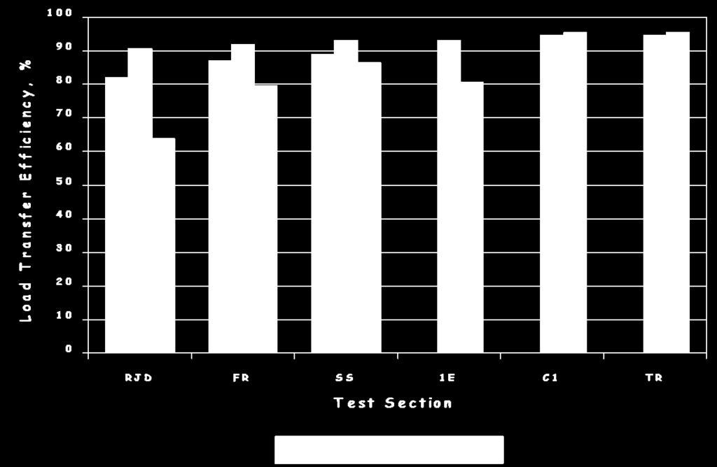
161 Figure 65. Transverse joint load transfer for outermost wheelpath on WI 2 (Crovetti 1999). Figure 66. Transverse joint load transfer for outermost wheelpath on WI 3 (Crovetti 1999). D-59
162 IRI, in/mi C1 1E 2E 3Ea 4E 4S 3S 3Eb HF RJD GF CP C2 1E FR RJD SS TR C1 Wisconsin 2 Sections Wisconsin 3 Sections Figure 67. Average IRI values in the outer traffic lanes of WI 2 and WI 3 pavement sections (Crovetti and Bischoff 2001). References Crovetti, J. A Cost Effective Concrete Pavement Cross-Sections. Report No. WI/SPR Wisconsin Department of Transportation, Madison, WI. Crovetti, J. A. and D. Bischoff Construction and Performance of Alternative Concrete Pavement Designs in Wisconsin. Preprint Paper No th Annual Meeting of the Transportation Research Board, Washington, DC. D-60
163 APPENDIX E REPORT ON WISCONSIN FIELD TESTING ACTIVITIES
164
165 1.0 Introduction This report presents the results of testing conducted in support of pooled fund study TPF 5(188), Evaluation of Fiber Reinforced Composite Dowel Bars and Stainless Steel Dowel Bars. Study objectives of TPF 5(188) include coring of alternative dowel bars, coring of epoxy coated dowel bars that have been in service for at least 15 years, and chloride analysis of cores for all types of dowel bars. Eight separate projects constructed in Wisconsin were included in this study. Table 1 provides a listing of these projects providing location, year of construction, and included dowel bar materials. Table 1: Wisconsin Projects Listing Project Year of Location Construction Included Dowel Bar Materials STH 67 Waukesha Co Epoxy Coated Steel IH 43 Sheboygan Co Epoxy Coated Steel IH 94 Dunn Co Epoxy Coated Steel USH 18/151 Dane Co Epoxy Coated Steel STH 29 Brown Co Epoxy Coated Steel STH 16 Waukesha Co Epoxy Coated Steel STH 29 Chippewa Co Epoxy Coated Steel STH 29 Clark Co Epoxy Coated Steel Solid Stainless Steel Mortar Filled Stainless Steel Tubes Fiber Reinforced Polymer (FRP) Field testing included falling weight deflectometer (FWD) testing (4 project locations) and the extraction of 6 inch diameter cores at selected dowel locations (all project locations). Extracted cores were transported to Marquette University for documentation and preparation of samples for chloride content testing. Chloride testing was conducted by Giles Engineering Associates, Inc. per ASTM C 1152, Test Method for Acid Soluble Residue in Mortar and Concrete. STH 67 Waukesha County This portion of STH 67 includes the southbound lanes constructed in 1976 from Pabst Road to Valley Road/CTH B in the Town of Oconomowoc. The project was overlaid prior to coring in November, Coring was conducted on November 24, A total of six cores were extracted from two sets of three consecutive joints randomly selected within the project limits. No FWD testing was conducted prior to the coring operations. E-1
166 IH 43 Sheboygan County This portion of IH 43 includes the southbound lanes constructed in 1979 before and after the bridge structure over STH 23 in the City of Sheboygan. Coring was conducted on November 19, A total of six cores were extracted from two sets of three consecutive joints randomly selected within the project limits. Due to traffic control restrictions, cores were extracted near the median shoulder of the passing lane. No FWD testing was conducted prior to the coring operations. IH 94 Dunn County This portion of IH 94 includes the eastbound lanes constructed in 1984 from Airport Rd/390 th Street to Wilson Creek Structure, which is just west of STH 25 interchange near the City of Menomonee. Coring was conducted on October 19, A total of six cores were extracted from two sets of three consecutive joints randomly selected within the project limits. FWD testing was conducted prior to the beginning of coring operations. However, equipment problems only allowed for the testing at the approach joint location on five consecutive joints. USH 18/151 Dane County This portion of USH 18/151 includes the eastbound lanes constructed in 1989 from Cave of the Mounds Road to STH 78 near the City of Mount Horeb. This portion of USH 18/151 includes unsealed random skewed transverse joints and both open graded (Section 13) and dense graded (Section 14) aggregate base layer sections. FWD testing and coring was conducted on June 16, FWD testing was conducted prior to the beginning of coring operations at five consecutive approach joint locations in each section. A total of six cores were extracted from three consecutive joints within section 13, with cores extracted from both the center lane and outside wheelpath locations. A total of three cores were extracted from two consecutive joints within section 14, with cores extracted from both the center lane and outside wheelpath locations. Coring equipment problems precluded the removal of the remaining three cores targeted for extraction. STH 29 Brown County This portion of STH 29 includes the eastbound lanes constructed in 1989 from Triangle Drive to Sunlite Drive just west of the City of Green Bay. This portion of STH 29 includes neoprene sealed (Section 3) and unsealed (Section 4) random skewed transverse joints over an open graded base layer. FWD testing and coring was conducted on June 30, FWD testing was conducted prior to the beginning of coring operations at six consecutive approach joint locations in each section. A total of three cores were extracted from three consecutive joints within each section, with cores extracted from the outside wheelpath location. E-2
167 STH 16 Waukesha County This portion of STH 16 includes the eastbound lanes constructed in 1990 between Gifford Rd/Brown St to CTH P near the Town of Oconomowoc. Coring was conducted on April 20, A total of three cores were extracted from three consecutive joints randomly selected within the project limits. No FWD testing was conducted prior to the coring operations. STH 29 Chippewa County This portion of STH 29 includes the eastbound lanes constructed in 1994 between CTH X and STH 27 near the Town of Cadott. Coring was conducted on October 20, A total of six cores were extracted from two sets of three consecutive joints randomly selected within the project limits. No FWD testing was conducted prior to the coring operations due to equipment problems. STH 29 Clark County This portion of STH 29 includes the eastbound lanes constructed in 1997 between Owens and Abbotsford, specifically from CTH X/Cardinal Ave to CTH E near the Town of Curtiss. This portion of STH 29 includes a widened outer lane (14 ft paved width striped at 12 ft) with unsealed random skewed transverse joints over a dense graded base layer. Dowels materials include standard epoxy coated steel (CTL), solid stainless steel (SS), mortar filled stainless steel tubes (HF), and fiber reinforced polymer (FRP) materials manufactured by Creative Pultrusions (CP), Glasforms (GF) and RJD Industries (RJ). FWD testing and coring was conducted on October 21, FWD testing was conducted prior to the beginning of coring operations at eight consecutive approach and leave joint locations in each section. The FWD joint testing was conducted in the outer wheel path (over dowel 4) and the results were used to select joints for coring. A total of four cores were extracted from two joints within the control (CTL) section, with cores extracted from the outside edge (dowel 3) and left centerlane location (dowel 10). These positions correspond to dowel locations 1 and 8 for a standard 12 ft wide pavement lane. A total of two cores were extracted from one joint within each of the remaining five sections (SS, HF, CP, GF, RJ), with cores extracted from the outside edge (dowel 3) and left centerlane location (dowel 10). 2.0 Core Documentation and Sample Preparation All collected pavement cores were transported to Marquette University for documentation and chloride content sample preparation. Photographs were taken of the cores, dowels and joint faces to document the condition of each. Notes on the condition of the concrete and dowels materials were recorded. Attachments A through H provide summary sheets for each collected core specimen. After documentation, chloride content specimens were prepared using a rotary hammer drill. The normal protocol included the following steps: E-3
168 1 The core sample was separated and the joint faces brushed to remove loose materials, typically composed of fine soil particles. The core section was then positioned in a stainless steel catch pan. 2 A clean, dry ¼ masonry bit was positioned on a mortar area slightly above the dowel level on one of the joint faces and penetrated for approximately ½ to produce a powdered sample of sufficient size. 3 The powdered materials were transferred from the catch pan and passed through a No. 20 sieve. The materials passing were captured in a brass sieve pan and mixed to ensure homogeneity. A 5g sample was obtained and transferred to a clean plastic sample bag. 4 The masonry bit, sieve and catch pans were brushed clean and Steps 2 and 3 were repeated on the other joint face to obtain a second 5g sample. 5 The two 5g samples were combined to obtain a single 10g sample representing the joint face materials. 6 The catch pans and sieve were brushed clean and a second clean, dry ¼ masonry bit was positioned in a mortar area slightly above the dowel level on one of the exterior core sections and penetrated for approximately ½ to produce a powdered sample of sufficient size. 7 The powdered materials were transferred from the catch pan and passed through a No. 20 sieve. The materials passing were captured in a brass sieve pan and mixed to ensure homogeneity. A 5g sample was obtained and transferred to a clean plastic sample bag. 8 The masonry bit, sieve and catch pans were brushed clean and Steps 6 and 7 were repeated on the other core section to obtain a second 5g sample. 9 The two 5g samples were combined to obtain a single 10g sample representing the outside core condition (approximately 3 in from the joint face) 10 The masonry bits, sieve, and catch pans were cleaned by dry brushing followed by a distilled water wash. All wetted surfaces were dried with a clean, disposable absorbent cloth and allowed to air dry before further use. The above procedure was applied to all cores received. However, four of the specimens received from STH 67 Waukesha Co. were in the form of completely disintegrated concrete with the extracted dowel and HMA overlay. Two of these specimens (Cores 1 & 2) contained sufficient fine materials to allow for the preparation of two 10g samples of P 20 materials by simply dry sieving the disintegrated concrete materials. These samples were arbitrarily marked as joint face and outside samples. The remaining two disintegrated specimens (Cores 5 & 6) contained essentially clean gravel sized materials with insufficient fine to produce test samples. 3.0 Chloride Content Testing All prepared samples were transported to Giles Engineering Associates, Inc. Chloride testing was conducted per ASTM C 1152, Test Method for Acid Soluble Residue in Mortar and Concrete. Table 2 provides a summary of the test results, including condition of the dowel bar and FWD test results, where available. E-4
169 Table 2: Test Results Highway Pavt Joint # FWD Test Results Dowel Chloride Content Segment Age Dowel Pos App LT% App DT* Lv LT% Lv DT* Deterioration Joint Face Outside STH67 Waukesha 33 1 D3 n.a. n.a. n.a. n.a. Extensive* STH67 Waukesha 33 2 D3 n.a. n.a. n.a. n.a. Extensive* STH67 Waukesha 33 3 D3 n.a. n.a. n.a. n.a. Moderate STH67 Waukesha 33 4 D3 n.a. n.a. n.a. n.a. Minor I 43 Sheboygan 30 1 D3 n.a. n.a. n.a. n.a. Moderate I 43 Sheboygan 30 2 D3 n.a. n.a. n.a. n.a. Minor I 43 Sheboygan 30 3 D3 n.a. n.a. n.a. n.a. Extensive I 43 Sheboygan 30 4 D3 n.a. n.a. n.a. n.a. Extensive I 43 Sheboygan 30 5 D3 n.a. n.a. n.a. n.a. None I 43 Sheboygan 30 6 D3 n.a. n.a. n.a. n.a. Extensive I 94 Dunn 25 3 D n.a. n.a. Extensive I 94 Dunn 25 4 D n.a. n.a. Minor I 94 Dunn 25 5 D n.a. n.a. Moderate I 94 Dunn D3 n.a. n.a. n.a. n.a. Moderate I 94 Dunn D3 n.a. n.a. n.a. n.a. Extensive I 94 Dunn D3 n.a. n.a. n.a. n.a. Moderate STH29 Brown 20 S3 Jt4 D n.a. n.a. Extensive STH29 Brown 20 S3 Jt5 D n.a. n.a. None STH29 Brown 20 S3 Jt6 D n.a. n.a. MOD STH29 Brown 20 S4 Jt1 D n.a. n.a. MOD STH29 Brown 20 S4 Jt2 D n.a. n.a. MOD STH29 Brown 20 S4 Jt3 D n.a. n.a. Minor USH18/151 Dane JT1 D n.a. n.a. Minor USH18/151 Dane JT1 D3 n.a. n.a. n.a. n.a. Minor USH18/151 Dane JT2 D n.a. n.a. None USH18/151 Dane JT2 D3 n.a. n.a. n.a. n.a. Minor USH18/151 Dane JT3 D n.a. n.a. None USH18/151 Dane JT3 D3 n.a. n.a. n.a. n.a. Minor USH18/151 Dane JT1 D n.a. n.a. NA USH18/151 Dane JT1 D3 n.a. n.a. n.a. n.a. NA USH18/151 Dane JT2 D n.a. n.a. NA STH16 Waukesha 19 1 D3 n.a. n.a. n.a. n.a. Extensive STH16 Waukesha 19 2 D3 n.a. n.a. n.a. n.a. Moderate STH16 Waukesha 19 3 D3 n.a. n.a. n.a. n.a. NA STH29 Chippewa 15 1 D3 n.a. n.a. n.a. n.a. None STH29 Chippewa 15 2 D3 n.a. n.a. n.a. n.a. Minor STH29 Chippewa 15 3 D3 n.a. n.a. n.a. n.a. Moderate STH29 Chippewa 15 4 D3 n.a. n.a. n.a. n.a. Minor STH29 Chippewa 15 5 D3 n.a. n.a. n.a. n.a. Minor STH29 Chippewa 15 6 D3 n.a. n.a. n.a. n.a. Minor STH 29 Clark 12 CTL JT6 D10 n.a. n.a. n.a. n.a. Minor STH 29 Clark 12 CTL JT6 D None STH 29 Clark 12 CTL JT7 D10 n.a. n.a. n.a. n.a. Extensive STH 29 Clark 12 CTL JT7 D None STH 29 Clark 12 CP JT3 D10 n.a. n.a. n.a. n.a. None* STH 29 Clark 12 CP JT3 D None* STH 29 Clark 12 GF JT7 D10 n.a. n.a. n.a. n.a. None* STH 29 Clark 12 GF JT7 D None* STH 29 Clark 12 RJ JT1 D10 n.a. n.a. n.a. n.a. Minor STH 29 Clark 12 RJ JT1 D None* STH 29 Clark 12 HF JT8 D10 n.a. n.a. n.a. n.a. None* STH 29 Clark 12 HF JT8 D None* STH 29 Clark 12 SS JT5 D10 n.a. n.a. n.a. n.a. None* STH 29 Clark 12 SS JT5 D None* App DT* and Lv DT* = total joint deflection in mils normalized to a load of 9,000 lb. None* = Fiber Reinforced Polymer Dowel, Extensive* indicates samples where no intact concrete was available. NA indicates core sample where no dowel bar was provided. E-5
170 4.0 Discussion of Results The aggregate results of the chloride content tests were compared against levels of dowel bar deterioration as noted for the epoxy coated steel dowels. Figure 1 provides a bar chart of the overall average and median results comparing dowel deterioration to chloride concentration levels. As shown, the overall average and median chloride concentrations are higher for the joint face samples than for the outside core samples for all test bins. However, there is no direct correlation between dowel deterioration and chloride concentrations; in fact overall average and median chloride concentrations are greatest for samples with none to minor dowel deterioration. Figure 1: Chloride Concentration vs Dowel Deteioration The effect of joint sealant and pavement age on chloride concentration levels is presented in Figures 2 and 3, with each data point representing and individual core sample test result. As shown, there appears to be little correlation between chloride concentration levels and pavement age for the unsealed joints. For those joints with neoprene sealants, chloride concentrations levels are generally lower than comparable measures for unsealed joints and these levels also increase with pavement age. E-6
171 Figure 2: Joint Face Chloride Concentration vs Pavement Age Figure 3: Outside Chloride Concentration vs Pavement Age E-7
172 Figure 4 presents the chloride concentration ratio versus pavement age, with the concentration ratio computed as: Chloride Concentration Ratio = Joint Face Concentration / Outside Concentration As shown, the concentration levels generally decrease with age, confirming the expected trend that the chloride ions penetrate further into the concrete over time. Figure 4: Chloride Concentration Ratio vs Pavement Age E-8
173 ATTACHMENT A Core Summary Sheets STH 67 Waukesha County E-9


174 Evaluation of Alternative Dowel Bar Materials Documentation of Cores Signs of Defects in Cores Taken Description Photos Core Number STH67 Waukesha C1 Core Intact, Y or N No Type of Joint Sealant NA Socketing around Unable to see dowel Corrosion of dowel at Extensive concrete interface Abrasion of the dowel Extensive surface at the crack face Dowel Deterioration Extensive Dowel Type Epoxy Coated PCC Deterioration Complete deterioration, only AC layer intact. PCC Stain Signs of Defect in Core holes Date when core was NA taken Dowel/Concrete Slab Interface Base Material Noted General Comments: All the pieces of the PCC were collected in a bag. The dowel bar is loose and the AC layer by itself. Note: All photos were taken placing Cores Upside down to facilitate balance. E-10


175 Evaluation of Alternative Dowel Bar Materials Documentation of Cores Signs of Defects in Cores Taken Description Photos Core Number STH67 Waukesha C2 Core Intact, Y or N No, PCC all desintegratedna Type of Joint Sealant NA Socketing around NA dowel Corrosion of dowel at Extensive concrete interface Abrasion of the dowel Extensive surface at the crack face Dowel Deterioration Extensive Dowel Type Epoxy Coated PCC Deterioration Extensive PCC Stain NA Signs of Defect in Core holes Date when core was taken Dowel/Concrete Slab Interface Base Material Noted General Comments: The aggregate is all in pieces. Note: All photos were taken placing Cores Upside down to facilitate balance. E-11


 Type of Joint Sealant NA")


176 Evaluation of Alternative Dowel Bar Materials Documentation of Cores Signs of Defects in Cores Taken Description Photos Core Number STH67 Waukesha C3 Core Intact, Y or N No (2 pieces) Type of Joint Sealant NA Socketing around Minor dowel Corrosion of dowel at Moderate in one end concrete interface Abrasion of the dowel Moderate surface at the crack face Dowel Deterioration Moderate Dowel Type Epoxy Coated PCC Deterioration Moderate PCC Stain Small dark spots in one side Signs of Defect in Core holes Date when core was NA taken Dowel/Concrete Slab Interface Base Material Noted General Comments: AC Overlay and dowel are attached to the PCC. Note: All photos were taken placing Cores Upside down to facilitate balance. E-12
177 Evaluation of Alternative Dowel Bar Materials Documentation of Cores Signs of Defects in Cores Taken Description Photos Core Number STH67 Waukesha C4 Core Intact, Y or N Yes Type of Joint Sealant NA Socketing around Yes dowel Corrosion of dowel at concrete interface Minor Abrasion of the dowel surface at the crack face Dowel Deterioration Dowel Type PCC Deterioration PCC Stain Minor, some orange color spots at ends Minor Epoxy Coated No Yes, dark and brown colors at dowel placement areas Signs of Defect in Core holes Date when core was NA taken Dowel/Concrete Slab Interface Base Material Noted General Comments: The AC Overlay layer is attached to PCC as well as the dowel. Note: All photos were taken placing Cores Upside down to facilitate balance. E-13


178 Evaluation of Alternative Dowel Bar Materials Documentation of Cores Signs of Defects in Cores Taken Description Photos Core Number STH67 Waukesha C5 Core Intact, Y or N No Type of Joint Sealant NA Socketing around Unable to see dowel Corrosion of dowel at Extensive concrete interface Abrasion of the dowel Extensive surface at the crack face Dowel Deterioration Extensive Dowel Type Epoxy Coated PCC Deterioration Extensive PCC Stain Unable to see Signs of Defect in Core holes Date when core was NA taken Dowel/Concrete Slab Interface Base Material Noted General Comments: The PCC core is disintegrated and there is only the layer of AC as an overlay. The dowel is loose and the PCC is gravel material. See photos. The core was wrapped with duck tape. After unwrapping, there was a lot of water running through the sample as seen in photos, Note: All photos were taken placing Cores Upside down to facilitate balance. E-14


179 Evaluation of Alternative Dowel Bar Materials Documentation of Cores Signs of Defects in Cores Taken Description Photos Core Number STH67 Waukesha C6 Core Intact, Y or N No Type of Joint Sealant NA Socketing around Extensive dowel Corrosion of dowel at Extensive concrete interface Abrasion of the dowel Extensive surface at the crack face Dowel Deterioration Extensive Dowel Type Epoxy Coated PCC Deterioration Yes, complete disintegration PCC Stain Signs of Defect in Core holes Date when core was NA taken Dowel/Concrete Slab Interface Base Material Noted General Comments: The core has an AC overlay layer. The PCC portion is disintegrated completely. After the duck tape was removed, water was found on the dowel and around that area. The water seemed to come from condensation (all wrapped with duck tape) from the coring process. Note: All photos were taken placing Cores Upside down to facilitate balance. E-15
180 ATTACHMENT B Core Summary Sheets IH 43 Sheboygan County E-16


181 Evaluation of Alternative Dowel Bar Materials Documentation of Cores Signs of Defects in Cores Taken Description Photos Core Number IH43 Sheboygan Jt1 D11 Core Intact, Y or N No (3 Pieces) Type of Joint Sealant Neoprene Socketing around Yes, moderate dowel Corrosion of dowel at Yes, minor concrete interface Abrasion of the dowel Extensive at joint surface at the crack face Dowel Deterioration Moderate Dowel Type Epoxy Coated PCC Deterioration Yes in some areas PCC Stain Yes, dark spots Signs of Defect in Core holes Date when core was NA taken Dowel/Concrete Slab Interface Base Material Noted General Comments: The core came in 3 big pieces; the dowel is still attached to one of the big pieces. Note: All photos were taken placing Cores Upside down to facilitate balance. E-17


 Type of")


182 Evaluation of Alternative Dowel Bar Materials Documentation of Cores Signs of Defects in Cores Taken Description Photos Core Number IH43 Sheboygan Jt2 D11 Core Intact, Y or N No (3 pieces) Type of Joint Sealant Neoprene Socketing around Yes, minor dowel Corrosion of dowel at Minor concrete interface Abrasion of the dowel Minor surface at the crack face Dowel Deterioration Minor Dowel Type Epoxy Coated PCC Deterioration No PCC Stain Yes, starting to show some yellowish spots, there is one dark area Signs of Defect in Core holes Date when core was NA taken Dowel/Concrete Slab Interface Base Material Noted General Comments: The bottom was opened with a hammer to be able to see the dowel. There are a total of 4 pieces. Note: All photos were taken placing Cores Upside down to facilitate balance. E-18


")


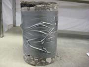
183 Evaluation of Alternative Dowel Bar Materials Documentation of Cores Signs of Defects in Cores Taken Description Photos Core Number IH43 Sheboygan Jt3 D11 Core Intact, Y or N No (3 pieces) Type of Joint Sealant Neoprene Socketing around Extensive dowel Corrosion of dowel at Extensive concrete interface Abrasion of the dowel Extensive surface at the crack face Dowel Deterioration Extensive Dowel Type Epoxy Coated PCC Deterioration Moderate inside core PCC Stain Yes, very dark in areas, some pieces from inside core are missing. Signs of Defect in Core holes Date when core was NA taken Dowel/Concrete Slab Interface Base Material Noted General Comments: Part of the PCC pieces are attached to bar and dowel attached to bigger PCC piece. Note: All photos were taken placing Cores Upside down to facilitate balance. E-19


184 Evaluation of Alternative Dowel Bar Materials Documentation of Cores Signs of Defects in Cores Taken Description Photos Core Number IH43 Sheboygan Jt4 D11 Core Intact, Y or N Yes Type of Joint Sealant Neoprene Socketing around Yes, some at the joint dowel Corrosion of dowel at Extensive concrete interface Abrasion of the dowel Extensive surface at the crack face Dowel Deterioration Extensive at joint Dowel Type Epoxy Coated PCC Deterioration No PCC Stain Yes, at dowel and joint below dowel, see photos. Signs of Defect in Core holes Date when core was NA taken Dowel/Concrete Slab Interface Base Material Noted General Comments: The core was broken with the electrical hammer to be able to see the dowel. There are 4 big pieces of PCC. Note: All photos were taken placing Cores Upside down to facilitate balance. E-20


185 Evaluation of Alternative Dowel Bar Materials Documentation of Cores Signs of Defects in Cores Taken Description Photos Core Number IH43 Sheboygan Jt5 D11 Core Intact, Y or N No Type of Joint Sealant Neoprene Socketing around dowel Yes, some at the joint see photos Corrosion of dowel at No concrete interface Abrasion of the dowel No surface at the crack face Dowel Deterioration No (at least at exposed areas of dowel) Dowel Type Epoxy Coated PCC Deterioration Minor PCC Stain No Signs of Defect in Core holes Date when core was NA taken Dowel/Concrete Slab Interface Base Material Noted General Comments: The dowel is still attached to main piece of PCC. There are a total of 3 big pieces, a lot of small pieces from the joint area. The PCC seems to be porous and crumbled. See photos. Note: All photos were taken placing Cores Upside down to facilitate balance. E-21


186 Evaluation of Alternative Dowel Bar Materials Documentation of Cores Signs of Defects in Cores Taken Description Photos Core Number IH43 Sheboygan Jt6 D11 Core Intact, Y or N No Type of Joint Sealant Neoprene Socketing around Yes dowel Corrosion of dowel at Extensive concrete interface Abrasion of the dowel Extensive surface at the crack face Dowel Deterioration Extensive Dowel Type Epoxy Coated PCC Deterioration Yes PCC Stain Yes, some dark areas Signs of Defect in Core holes Date when core was NA taken Dowel/Concrete Slab Interface Base Material Noted General Comments: There is a lot of loose aggregate. See photos. Note: All photos were taken placing Cores Upside down to facilitate balance. E-22
187 ATTACHMENT C Core Summary Sheets IH 94 Dunn County E-23


188 Evaluation of Alternative Dowel Bar Materials Documentation of Cores Signs of Defects in Cores Taken Description Photos Core Number IH94 Dunn Jt3 D3 Core Intact, Y or N No Type of Joint Sealant Neoprene Socketing around Some slightly dowel Corrosion of dowel at Extensive concrete interface Abrasion of the dowel Extensive surface at the crack face Dowel Deterioration Extensive Dowel Type Epoxy Coated PCC Deterioration Moderate PCC Stain Dark colors around the dowel Signs of Defect in Core holes Date when core was NA taken Dowel/Concrete Slab Interface Base Material Noted General Comments: There are 4 big pieces, one medium piece attached to corroded dowel. The rest of small pieces were collected in a bag. Note: All photos were taken placing Cores Upside down to facilitate balance. E-24


189 Evaluation of Alternative Dowel Bar Materials Documentation of Cores Signs of Defects in Cores Taken Description Photos Core Number IH94 Dunn Jt4 Core Intact, Y or N No Type of Joint Sealant Liquid Hot Poured AC Socketing around No dowel Corrosion of dowel at Minor concrete interface Abrasion of the dowel Minor surface at the crack face Dowel Deterioration Minor Dowel Type Epoxy Coated PCC Deterioration Yes PCC Stain Yes, dark browns Signs of Defect in Core holes Date when core was taken Dowel/Concrete Slab Interface Base Material Noted General Comments: PCC dark at joint and dowel area. Corrosion of dowel mainly at joint, dark browns. PCC broken into 5 pieces. Note: All photos were taken placing Cores Upside down to facilitate balance. E-25


 PCC Stain")


190 Evaluation of Alternative Dowel Bar Materials Documentation of Cores Signs of Defects in Cores Taken Description Photos Core Number IH94 Dunn Jt5 D3 Core Intact, Y or N No Type of Joint Sealant Neoprene Socketing around Minor dowel Corrosion of dowel at Moderate concrete interface Abrasion of the dowel Moderate surface at the crack face Dowel Deterioration Moderate Dowel Type Epoxy Coated PCC Deterioration Moderate (core is crumbled) PCC Stain No visible to the pieces available Signs of Defect in Core holes Date when core was NA taken Dowel/Concrete Slab Interface Base Material Noted General Comments: There are 3 big pieces, a lot of little pieces and dowel is attached to the big piece. Note: All photos were taken placing Cores Upside down to facilitate balance. E-26


191 Evaluation of Alternative Dowel Bar Materials Documentation of Cores Signs of Defects in Cores Taken Description Photos Core Number IH94 Dunn Jt40 Core Intact, Y or N No (4 pieces) Type of Joint Sealant Liquid Hot Poured Socketing around Very little dowel Corrosion of dowel at Moderate concrete interface Abrasion of the dowel Moderate surface at the crack face Dowel Deterioration Moderate Dowel Type Epoxy Coated PCC Deterioration Minor PCC Stain Some spots at dowel placing area Signs of Defect in Core holes Date when core was taken Dowel/Concrete Slab Interface Base Material Noted General Comments: There are 4 big pieces of PCC, dowel is loose and joint sealant still attached to PCC Note: All photos were taken placing Cores Upside down to facilitate balance. E-27


192 Evaluation of Alternative Dowel Bar Materials Documentation of Cores Signs of Defects in Cores Taken Description Photos Core Number IH94 Dunn Jt41 Core Intact, Y or N No Type of Joint Sealant Hot Poured Asphalt Socketing around Some dowel Corrosion of dowel at Extensive concrete interface Abrasion of the dowel Extensive surface at the crack face Dowel Deterioration Extensive Dowel Type Epoxy Coated PCC Deterioration Some, top half missing PCC Stain YES, dark browns and yellows, rust colors Signs of Defect in Core holes Date when core was taken Dowel/Concrete Slab NA Interface Base Material Noted No General Comments: 3 Big PCC pieces, 1 medium which was very stained, and a lot of small pieces hard to collect. Note: All photos were taken placing Cores Upside down to facilitate balance E-28


193 Evaluation of Alternative Dowel Bar Materials Documentation of Cores Signs of Defects in Cores Taken Description Photos Core Number IH94 Dunn Jt42 Core Intact, Y or N No Type of Joint Sealant NA Socketing around No dowel Corrosion of dowel at Moderate concrete interface Abrasion of the dowel Moderate surface at the crack face Dowel Deterioration Moderate Dowel Type Epoxy Coated PCC Deterioration 5 main PCC pieces, a lot of crumbled concrete especially around the dowel. High quantity of disintegrated concrete. PCC Stain Signs of Defect in Core holes Date when core was taken Dowel/Concrete Slab Interface Base Material Noted General Comments: Note: All photos were taken placing Cores Upside down to facilitate balance. E-29
194 ATTACHMENT D Core Summary Sheets USH 18/151 Dane County E-30

 Type of")


195 Evaluation of Alternative Dowel Bar Materials Documentation of Cores Signs of Defects in Cores Taken Description Photos Core Number USH18 Dane S13 Jt2 D3 Core Intact, Y or N No (only available top portion) Type of Joint Sealant NA Socketing around None dowel Corrosion of dowel at NA concrete interface Abrasion of the dowel NA surface at the crack face Dowel Deterioration NA Dowel Type NA PCC Deterioration Minor at joint PCC Stain Signs of Defect in Core holes Date when core was taken Dowel/Concrete Slab Interface Base Material Noted General Comments: Dowel was not available, only top portion of core. Note: All photos were taken placing Cores Upside down to facilitate balance. E-31


196 Evaluation of Alternative Dowel Bar Materials Documentation of Cores Signs of Defects in Cores Taken Description Photos Core Number USH18 Dane S13 Jt2 D11 Core Intact, Y or N Yes Type of Joint Sealant NA Socketing around No dowel Corrosion of dowel at No concrete interface Abrasion of the dowel No surface at the crack face Dowel Deterioration One small spot, light brown Dowel Type Epoxy Coated PCC Deterioration Some after core was opened with electrical hammer. PCC Stain Signs of Defect in Core holes Date when core was taken Dowel/Concrete Slab Interface Base Material Noted General Comments: The core was opened with an electrical hammer to be able to observe the dowel. The core was broken into 3 big pieces, 3 medium and a lot of small ones. Note: All photos were taken placing Cores Upside down to facilitate balance. E-32


197 Evaluation of Alternative Dowel Bar Materials Documentation of Cores Signs of Defects in Cores Taken Description Photos Core Number USH18 Dane S13 Jt3 D3 Core Intact, Y or N Yes Type of Joint Sealant NA Socketing around No dowel Corrosion of dowel at Yes concrete interface Abrasion of the dowel Minor surface at the crack face Dowel Deterioration Minor Dowel Type Epoxy Coated PCC Deterioration No PCC Stain Yes, a few colors of orange and dark brown spots Signs of Defect in Core holes Date when core was taken Dowel/Concrete Slab Interface Base Material Noted General Comments: The core was broken with the electrical hammer to be able to observe the inside. Now there are 3 big pieces and 1 medium Note: All photos were taken placing Cores Upside down to facilitate balance. E-33


198 Evaluation of Alternative Dowel Bar Materials Documentation of Cores Note: All photos were taken placing Cores Upside down to facilitate balance. Signs of Defects in Cores Taken Description Photos Core Number USH18 Dane S13 Jt3 D11 Core Intact, Y or N Yes Type of Joint Sealant NA Socketing around No dowel Corrosion of dowel at concrete interface Only at the ends where the core is cut Abrasion of the dowel No surface at the crack face Dowel Deterioration No Dowel Type Epoxy Coated PCC Deterioration No PCC Stain A few spots starting to turn yellowish Signs of Defect in Core holes Date when core was taken Dowel/Concrete Slab Interface Base Material Noted General Comments: The core was opened with an electrical hammer. There are 3 big pieces and dowel is still attached to bigger piece. There are also 3 small pieces that belong to the area of joint/dowel. E-34


199 Evaluation of Alternative Dowel Bar Materials Documentation of Cores Signs of Defects in Cores Taken Description Photos Core Number USH18 Dane S13 Jt4 D3 Core Intact, Y or N No (2 pieces) Type of Joint Sealant None Socketing around None dowel Corrosion of dowel at A few small spots visible concrete interface Abrasion of the dowel No surface at the crack face Dowel Deterioration Minor, rusted at edges of cut Dowel Type Epoxy Coated PCC Deterioration No PCC Stain Minor, only at joints due to pollution Signs of Defect in Core holes Date when core was taken Dowel/Concrete Slab Interface Base Material Noted General Comments: This core was also opened with electrical hammer to observe the inside. Total pieces 4. Note: All photos were taken placing Cores Upside down to facilitate balance. E-35


200 Evaluation of Alternative Dowel Bar Materials Documentation of Cores Signs of Defects in Cores Taken Description Photos Core Number USH18 Dane S13 Jt4 D11 Core Intact, Y or N Yes Type of Joint Sealant NA Socketing around No dowel Corrosion of dowel at No concrete interface Abrasion of the dowel No surface at the crack face Dowel Deterioration No Dowel Type Epoxy Coated PCC Deterioration No PCC Stain No Signs of Defect in Core holes Date when core was taken Dowel/Concrete Slab Interface Base Material Noted General Comments: The core was broken with electrical hammer to be able to observe the inside of the core. The dowel was in perfect shape. The PCC gor broken in a laminated shapes. Note: All photos were taken placing Cores Upside down to facilitate balance. E-36


201 Evaluation of Alternative Dowel Bar Materials Documentation of Cores Signs of Defects in Cores Taken Description Photos Core Number USH18 Dane S14 Jt1 D3 Core Intact, Y or N No Type of Joint Sealant NA Socketing around dowel Dowel missing but apparently none Corrosion of dowel at NA concrete interface Abrasion of the dowel NA surface at the crack face Dowel Deterioration NA Dowel Type NA PCC Deterioration Bottom portion is missing PCC Stain Dark at joint due to pollution Signs of Defect in Core holes Date when core was taken Dowel/Concrete Slab Interface Base Material Noted General Comments: Only 2 big pieces of PCC and no dowel to analyze. Note: All photos were taken placing Cores Upside down to facilitate balance. E-37


202 Evaluation of Alternative Dowel Bar Materials Documentation of Cores Signs of Defects in Cores Taken Description Photos Core Number USH18 Dane S14 Jt1 D11 Core Intact, Y or N No Type of Joint Sealant NA Socketing around No dowel Corrosion of dowel at No Dowel available concrete interface Abrasion of the dowel No Dowel available surface at the crack face Dowel Deterioration NA Dowel Type NA PCC Deterioration None PCC Stain None Signs of Defect in Core holes Date when core was taken Dowel/Concrete Slab Interface Base Material Noted General Comments: Only the top half of the core was available. No dowel included. Note: All photos were taken placing Cores Upside down to facilitate balance. E-38


203 Evaluation of Alternative Dowel Bar Materials Documentation of Cores Signs of Defects in Cores Taken Description Photos Core Number USH18 Dane S14 Jt2 D11 Core Intact, Y or N No (2 pieces) Type of Joint Sealant NA Socketing around No dowel Corrosion of dowel at No Dowel to evaluate concrete interface Abrasion of the dowel NA surface at the crack face Dowel Deterioration NA Dowel Type NA PCC Deterioration No PCC Stain Yes, some spots and dark material at joint. Signs of Defect in Core holes Date when core was taken Dowel/Concrete Slab Interface Base Material Noted General Comments: No dowel was available to evaluate. Note: All photos were taken placing Cores Upside down to facilitate balance. E-39
204 ATTACHMENT E Core Summary Sheets STH 29 Brown County E-40


205 Evaluation of Alternative Dowel Bar Materials Documentation of Cores Signs of Defects in Cores Taken Description Photos Core Number STH29 Brown S3 Jt4 D3 Core Intact, Y or N No Type of Joint Sealant Neoprene Socketing around None dowel Corrosion of dowel at Moderate concrete interface Abrasion of the dowel Moderate surface at the crack face Dowel Deterioration Significantly at joint Dowel Type Epoxy Coated PCC Deterioration Moderate at joints and minor at bottom PCC Stain Yes, colors ranging from dark browns and oranges, dark colors mainly at joint. Signs of Defect in Core holes Date when core was taken Dowel/Concrete Slab NA Interface Base Material Noted NA General Comments: PCC in 4 big pieces. Note: All photos were taken placing Cores Upside down to facilitate balance. E-41


206 Evaluation of Alternative Dowel Bar Materials Documentation of Cores Signs of Defects in Cores Taken Description Photos Core Number STH29 Brown S3 Jt5 D3 Core Intact, Y or N Yes Type of Joint Sealant Neoprene Socketing around No dowel Corrosion of dowel at Moderate concrete interface Abrasion of the dowel Moderate surface at the crack face Dowel Deterioration Moderate Dowel Type Epoxy Coated PCC Deterioration No PCC Stain Yes, spots of colors yellow, dark browns and dark oranges Signs of Defect in Core holes Date when core was taken Dowel/Concrete Slab Interface Base Material Noted General Comments: There are now a total of 4 pieces after core was opened with an electrical hammer. There are 3 big pieces and 1 medium. Note: All photos were taken placing Cores Upside down to facilitate balance. E-42


207 Evaluation of Alternative Dowel Bar Materials Documentation of Cores Signs of Defects in Cores Taken Description Photos Core Number STH29 Brown S3 Jt6 D3 Core Intact, Y or N No (3 pieces) Type of Joint Sealant NA Socketing around Minor dowel Corrosion of dowel at Yes, all around concrete interface Abrasion of the dowel Yes, all length surface at the crack face Dowel Deterioration Moderate Dowel Type Epoxy Coated PCC Deterioration No PCC Stain Yes, dark brown areas Signs of Defect in Core holes Date when core was NA taken Dowel/Concrete Slab Interface Base Material Noted General Comments: The core was hammered to observe the rest of the dowel. There are 4 main pieces, 2 medium pieces and some small. The dowel is still attached to ¼ of PCC. Note: All photos were taken placing Cores Upside down to facilitate balance. E-43


208 Evaluation of Alternative Dowel Bar Materials Documentation of Cores Signs of Defects in Cores Taken Description Photos Core Number STH29 Brown S4 Jt1 D3 Core Intact, Y or N No Type of Joint Sealant NA Socketing around Minor dowel Corrosion of dowel at Moderate concrete interface Abrasion of the dowel Moderate surface at the crack face Dowel Deterioration Yes Dowel Type Epoxy Coated PCC Deterioration Minor PCC Stain Yes, dark browns and oranges by corroded areas. Signs of Defect in Core holes Date when core was taken Dowel/Concrete Slab Interface Base Material Noted General Comments: There are 4 big pieces and one medium. The dowel is loose. Note: All photos were taken placing Cores Upside down to facilitate balance E-44


209 Evaluation of Alternative Dowel Bar Materials Documentation of Cores Signs of Defects in Cores Taken Description Photos Core Number STH29 Brown S4 Jt2 D3 Core Intact, Y or N Yes Type of Joint Sealant NA Socketing around No dowel Corrosion of dowel at Yes concrete interface Abrasion of the dowel Minor surface at the crack face Dowel Deterioration Minor Dowel Type Epoxy Coated PCC Deterioration No PCC Stain Yes (mainly at joint, dark brown spots) Signs of Defect in Core holes Date when core was taken Dowel/Concrete Slab Interface Base Material Noted General Comments: The core was broken with an electrical hammer to be able to see the dowel. The core consist of 4 big pieces and the dowel is loose. Note: All photos were taken placing Cores Upside down to facilitate balance. E-45


210 Evaluation of Alternative Dowel Bar Materials Documentation of Cores Signs of Defects in Cores Taken Description Photos Core Number STH29 Brown S4 Jt3 D3 Core Intact, Y or N No (4 pieces) Type of Joint Sealant NA Socketing around No dowel Corrosion of dowel at Minor concrete interface Abrasion of the dowel Moderate surface at the crack face Dowel Deterioration Minor Dowel Type Epoxy Coated PCC Deterioration Minor PCC Stain One spot very dark brown and orange Signs of Defect in Core holes Date when core was taken Dowel/Concrete Slab No Interface Base Material Noted General Comments: There are 2 small pieces of PCC with stain and attached to the duck tape Note: All photos were taken placing Cores Upside down to facilitate balance. E-46
211 ATTACHMENT F Core Summary Sheets STH 16 Waukesha County E-47


212 Evaluation of Alternative Dowel Bar Materials Documentation of Cores Signs of Defects in Cores Taken Description Photos Core Number STH16 Waukesha C1 Core Intact, Y or N Yes, only available top portion of core Type of Joint Sealant NA Socketing around No dowel Corrosion of dowel at Extensive concrete interface Abrasion of the dowel Extensive surface at the crack face Dowel Deterioration Extensive Dowel Type Epoxy Coated PCC Deterioration Minor PCC Stain Unable to observe Signs of Defect in Core holes Date when core was taken Dowel/Concrete Slab Interface Base Material Noted General Comments: PCC need to be hammered drilled to separate sides to observe joint face. Note: All photos were taken placing Cores Upside down to facilitate balance. E-48


213 Evaluation of Alternative Dowel Bar Materials Documentation of Cores Signs of Defects in Cores Taken Description Photos Core Number STH16 Waukesha C2 Core Intact, Y or N No Type of Joint Sealant NA Socketing around NA dowel Corrosion of dowel at Moderate concrete interface Abrasion of the dowel Moderate surface at the crack face Dowel Deterioration Moderate Dowel Type Epoxy Coated PCC Deterioration Minor PCC Stain Unable to see Signs of Defect in Core holes Date when core was taken Dowel/Concrete Slab Interface Base Material Noted General Comments: This core came in 3 pieces, 2PCC and the dowel. Unable to see any stain in PCC. The dowel was loose and moderately corroded. Note: All photos were taken placing Cores Upside down to facilitate balance. E-49


 and dowel was")


214 Evaluation of Alternative Dowel Bar Materials Documentation of Cores Signs of Defects in Cores Taken Description Photos Core Number STH16 Waukesha C3 Core Intact, Y or N No Type of Joint Sealant NA Socketing around NA dowel Corrosion of dowel at NA concrete interface Abrasion of the dowel NA surface at the crack face Dowel Deterioration NA Dowel Type Dowel Missing PCC Deterioration Minor PCC Stain Yes, a few spots light brown where dowelsits. Signs of Defect in Core holes Date when core was taken Dowel/Concrete Slab Interface Base Material Noted General Comments: The core came with only 2 pieces of PCC (top portion) and dowel was missing. Regarding the joint seal, it was missing but looking at the core, it could have been neoprene. See last 2 photos of this page. Note: All photos were taken placing Cores Upside down to facilitate balance E-50


215 Evaluation of Alternative Dowel Bar Materials Documentation of Cores Signs of Defects in Cores Taken Description Photos Core Number STH67 Waukesha C4 Core Intact, Y or N Yes Type of Joint Sealant NA Socketing around Yes dowel Corrosion of dowel at concrete interface Minor Abrasion of the dowel surface at the crack face Dowel Deterioration Dowel Type PCC Deterioration PCC Stain Minor, some orange color spots at ends Minor Epoxy Coated No Yes, dark and brown colors at dowel placement areas Signs of Defect in Core holes Date when core was NA taken Dowel/Concrete Slab Interface Base Material Noted General Comments: The AC Overlay layer is attached to PCC as well as the dowel. Note: All photos were taken placing Cores Upside down to facilitate balance. E-51
216 ATTACHMENT G Core Summary Sheets STH 29 Chippewa County E-52


217 Evaluation of Alternative Dowel Bar Materials Documentation of Cores Signs of Defects in Cores Taken Description Photos Core Number STH29 Chippewa C1 D3 Core Intact, Y or N No (4 Big pieces) Type of Joint Sealant NA Socketing around No dowel Corrosion of dowel at Small orange spot concrete interface Abrasion of the dowel Only at cut edges surface at the crack face Dowel Deterioration No Dowel Type Epoxy Coated PCC Deterioration Yes, minor PCC Stain No stains Signs of Defect in Core holes Date when core was NA taken Dowel/Concrete Slab Interface Base Material Noted General Comments: The dowel is still attached to one of the PCC pieces. Note: All photos were taken placing Cores Upside down to facilitate balance. E-53


218 Evaluation of Alternative Dowel Bar Materials Documentation of Cores Signs of Defects in Cores Taken Description Photos Core Number STH29 Chippewa C4 D3 Core Intact, Y or N No Type of Joint Sealant NA Socketing around No dowel Corrosion of dowel at concrete interface Minimal, there is brown spots at edges Abrasion of the dowel Minor surface at the crack face Dowel Deterioration Minor Dowel Type Epoxy Coated PCC Deterioration No PCC Stain One spot light yellow Signs of Defect in Core holes Date when core was taken Dowel/Concrete Slab Interface Base Material Noted General Comments: There are 4 PCC big pieces and the dowel is loose. Note: All photos were taken placing Cores Upside down to facilitate balance E-54


219 Evaluation of Alternative Dowel Bar Materials Documentation of Cores Signs of Defects in Cores Taken Description Photos Core Number STH29 Chippewa C6 D3 Core Intact, Y or N No Type of Joint Sealant NA Socketing around Minor dowel Corrosion of dowel at Yes, minor concrete interface Abrasion of the dowel Moderate surface at the crack face Dowel Deterioration Minor Dowel Type Epoxy Coated PCC Deterioration Yes, minor PCC Stain Orange and dark brown spots in one area only Signs of Defect in Core holes Date when core was taken Dowel/Concrete Slab Interface Base Material Noted General Comments: There are 4 big pieces, 1 medium and dowel is loose. Note: All photos were taken placing Cores Upside down to facilitate balance. E-55
220 ATTACHMENT H Core Summary Sheets STH 29 Clark County E-56


221 Evaluation of Alternative Dowel Bar Materials Documentation of Cores Signs of Defects in Cores Taken Description Photos Core Number STH29 Clark C1 Jt6 D3 Core Intact, Y or N Yes Type of Joint Sealant NA Socketing around No dowel Corrosion of dowel at Minor concrete interface Abrasion of the dowel Minor surface at the crack face Dowel Deterioration No Dowel Type Epoxy Coated Steel PCC Deterioration No PCC Stain One spot very dark Signs of Defect in Core holes Date when core was 10/21/2009 taken Dowel/Concrete Slab Interface Base Material Noted General Comments: The core was hammered to be able to observe the dowel and PCCC. There are now 3 big pieces. Note: All photos were taken placing Cores Upside down to facilitate balance. E-57


222 Evaluation of Alternative Dowel Bar Materials Documentation of Cores Signs of Defects in Cores Taken Description Photos Core Number STH29 Clark C1 Jt6 D11 Core Intact, Y or N No Type of Joint Sealant NA Socketing around No dowel Corrosion of dowel at No concrete interface Abrasion of the dowel No surface at the crack face Dowel Deterioration Yes, some oxidation at cut areas. Dowel Type Epoxy Coated Steel PCC Deterioration Minor PCC Stain None Signs of Defect in Core holes Date when core was 10/21/2009 taken Dowel/Concrete Slab Interface Base Material Noted General Comments: There are 4 big pieces, 1 medium and the dowel is loose. Note: All photos were taken placing Cores Upside down to facilitate balance. E-58


223 Evaluation of Alternative Dowel Bar Materials Documentation of Cores Signs of Defects in Cores Taken Description Photos Core Number STH29 Clark C1 Jt7 D3 Core Intact, Y or N No (4 big pieces) Type of Joint Sealant NA Socketing around No dowel Corrosion of dowel at concrete interface Only at ends where cut was cut and taped. Abrasion of the dowel No surface at the crack face Dowel Deterioration No Dowel Type Epoxy Coated Steel PCC Deterioration Minor PCC Stain Yes, light browns and yelllows Signs of Defect in Core holes Date when core was 10/21/2009 taken Dowel/Concrete Slab Interface Base Material Noted General Comments: The core is broken in 4 big pieces and the dowel is loose. Note: All photos were taken placing Cores Upside down to facilitate balance. E-59


224 Evaluation of Alternative Dowel Bar Materials Documentation of Cores Signs of Defects in Cores Taken Description Photos Core Number STH29 Clark CI Jt7 D11 Core Intact, Y or N No Type of Joint Sealant NA Socketing around Minor dowel Corrosion of dowel at Minor concrete interface Abrasion of the dowel Extensive surface at the crack face Dowel Deterioration Yes Dowel Type Epoxy Coated Steel PCC Deterioration Yes, core crumbled PCC Stain No Signs of Defect in Core holes Date when core was 10/21/2009 taken Dowel/Concrete Slab Interface Base Material Noted General Comments: The core is broken into 4 big pieces, 3 medium, dowel is loose and a lot of small pieces. Note: All photos were taken placing Cores Upside down to facilitate balance. E-60


")


")


225 Evaluation of Alternative Dowel Bar Materials Documentation of Cores Signs of Defects in Cores Taken Description Photos Core Number STH29 Clark CP Jt3 D3 Core Intact, Y or N No (a lot of small pieces) Type of Joint Sealant NA Socketing around Yes, at joints, moderate dowel Corrosion of dowel at No concrete interface Abrasion of the dowel No surface at the crack face Dowel Deterioration No Dowel Type Creative Pultrusions FRP (Fiber Reinforced Polymer) PCC Deterioration Moderate PCC Stain None Signs of Defect in Core holes Date when core was taken Dowel/Concrete Slab Interface Base Material Noted General Comments: There are 3 big pieces, 1 medium, and dowel attached to bigger piece. There are also a lot of small pieces from crumbled PCC) Dark also at joint due to pollution. Note: All photos were taken placing Cores Upside down to facilitate balance. E-61


226 Evaluation of Alternative Dowel Bar Materials Documentation of Cores Signs of Defects in Cores Taken Description Photos Core Number STH29 Clark CP Jt3 D11 Core Intact, Y or N No Type of Joint Sealant NA Socketing around No dowel Corrosion of dowel at No concrete interface Abrasion of the dowel No surface at the crack face Dowel Deterioration No Dowel Type Creative Pultrusions FRP (Fiber Reinforced Polymer) PCC Deterioration Minor PCC Stain No Signs of Defect in Core holes Date when core was 10/21/2009 taken Dowel/Concrete Slab Interface Base Material Noted General Comments: The dowel is attached to one of the PCC pieces. A total of 8 pieces. Note: All photos were taken placing Cores Upside down to facilitate balance E-62


227 Evaluation of Alternative Dowel Bar Materials Documentation of Cores Signs of Defects in Cores Taken Description Photos Core Number STH29 Clark GF Jt7 D3 Core Intact, Y or N No Type of Joint Sealant NA Socketing around No dowel Corrosion of dowel at Dark areas at joints concrete interface Abrasion of the dowel No surface at the crack face Dowel Deterioration No Dowel Type Glasforms FRP (Fiber Reinforced Polymer) PCC Deterioration Moderate PCC Stain Some dark areas at joint Signs of Defect in Core holes Date when core was 10/21/2009 taken Dowel/Concrete Slab Interface Base Material Noted General Comments: There are 4 big pieces, dowel attached to ¼ of the core. There is one medium piece and small pieces from PCC crumbled. Note: All photos were taken placing Cores Upside down to facilitate balance. E-63


 Type of Joint Sealant")


228 Evaluation of Alternative Dowel Bar Materials Documentation of Cores Signs of Defects in Cores Taken Description Photos Core Number STH29 Clark GF Jt7 D11 Core Intact, Y or N No (6 pieces) Type of Joint Sealant NA Socketing around None dowel Corrosion of dowel at None concrete interface Abrasion of the dowel None surface at the crack face Dowel Deterioration None Dowel Type Glasforms FRP (Filled Reinforced Polymer) PCC Deterioration Very manor due to the breaking of the core when extracted. PCC Stain There are dark gray areas which believed to be from pollution due to lacking of joint seal. Signs of Defect in Core holes Date when core was 10/21/2009 taken Dowel/Concrete Slab Interface Base Material Noted General Comments: A total of 6 big PCC pieces. Dark color of PCC at joint (see last photo in this page) Note: All photos were taken placing Cores Upside down to facilitate balance. E-64


 PCC")


229 Evaluation of Alternative Dowel Bar Materials Documentation of Cores Signs of Defects in Cores Taken Description Photos Core Number STH29 Clark RJ Jt1 D3 Core Intact, Y or N No Type of Joint Sealant NA Socketing around No dowel Corrosion of dowel at concrete interface Yes, some dark spots at joint Abrasion of the dowel No surface at the crack face Dowel Deterioration No Dowel Type RJD FRP (Fiber Reinforced Polymer) PCC Deterioration Yes, some crumbled PCC Stain Yes, some dark spots at dowel placement Signs of Defect in Core holes Date when core was 10/21/2009 taken Dowel/Concrete Slab Interface Base Material Noted General Comments: There are 4 big pieces, one medium and a lot of small pieces. The dowel is still attached to ¼ of the PCC core. Note: All photos were taken placing Cores Upside down to facilitate balance. E-65


230 Evaluation of Alternative Dowel Bar Materials Documentation of Cores Signs of Defects in Cores Taken Description Photos Core Number STH29 Clark RJ Jt1 D11 Core Intact, Y or N No (5 pieces) Type of Joint Sealant NA Socketing around No dowel Corrosion of dowel at Minor in one side concrete interface Abrasion of the dowel No surface at the crack face Dowel Deterioration Minor Dowel Type RJD FRP (Fiber Reinforced Polymer) PCC Deterioration Minor PCC Stain Some dark brown areas Signs of Defect in Core holes Date when core was 10/21/2009 taken Dowel/Concrete Slab Interface Base Material Noted General Comments: The core is broken into 5 pieces and the dowel is loose. Note: All photos were taken placing Cores Upside down to facilitate balance. E-66


231 Evaluation of Alternative Dowel Bar Materials Documentation of Cores Signs of Defects in Cores Taken Description Photos Core Number STH29 Clark HF Jt8 D3 Core Intact, Y or N No (6 pieces) Type of Joint Sealant NA Socketing around No dowel Corrosion of dowel at No concrete interface Abrasion of the dowel No surface at the crack face Dowel Deterioration No Dowel Type Mortar Filled Stainless Steel Tube PCC Deterioration Minor PCC Stain Only one dark area Signs of Defect in Core holes Date when core was 10/21/2009 taken Dowel/Concrete Slab Interface Base Material Noted General Comments: There are 3 big pieces of PCC, 3 medium pieces and dowel is loose. Note: All photos were taken placing Cores Upside down to facilitate balance. E-67


232 Evaluation of Alternative Dowel Bar Materials Documentation of Cores Signs of Defects in Cores Taken Description Photos Core Number STH29 Clark HF JT8 D11 Core Intact, Y or N No Type of Joint Sealant None Socketing around None dowel Corrosion of dowel at None concrete interface Abrasion of the dowel None surface at the crack face Dowel Deterioration None Dowel Type Mortar Filled Stainless Steel Tube PCC Deterioration None PCC Stain None Signs of Defect in Core holes Date when core was 10/21/2009 taken Dowel/Concrete Slab Interface Base Material Noted General Comments: PCC broken in 4 pieces, dowel still attached to main PCC piece. Note: All photos were taken placing Cores Upside down to facilitate balance. E-68


233 Evaluation of Alternative Dowel Bar Materials Documentation of Cores Signs of Defects in Cores Taken Description Photos Core Number STH29 Clark SS Jt5 D3 Core Intact, Y or N No Type of Joint Sealant NA Socketing around dowel Yes, PCC crumbling at joint Corrosion of dowel at No concrete interface Abrasion of the dowel No surface at the crack face Dowel Deterioration No Dowel Type Solid Stainless Steel PCC Deterioration Yes PCC Stain Some darker areas at joint. Could be due to dirt and pollution Signs of Defect in Core holes Date when core was 10/21/2009 taken Dowel/Concrete Slab Interface Base Material Noted No General Comments: There are 4 big pieces of PCC and one medium. Dowel is not attached to any of the pieces. Note: All photos were taken placing Cores Upside down to facilitate balance. E-69


234 Evaluation of Alternative Dowel Bar Materials Documentation of Cores Signs of Defects in Cores Taken Description Photos Core Number STH29 Clark SS Jt5 D11 Core Intact, Y or N No (this core was staked inside of the core bit in big pieces) Type of Joint Sealant NA Socketing around dowel Unable to see the core all together Corrosion of dowel at NA concrete interface Abrasion of the dowel None surface at the crack face Dowel Deterioration None Dowel Type Solid Stainless Steel PCC Deterioration Unable to see. It had to be broken to extract it from core bit. PCC Stain Minor shaded areas or dark stain Signs of Defect in Core holes Date when core was 10/21/2009 taken Dowel/Concrete Slab Interface Base Material Noted General Comments: There are a lot of pieces due to the breaking to extract the core from core bit. Note: All photos were taken placing Cores Upside down to facilitate balance. E-70
TPF-5(188), Evaluation of Fiber Reinforced Composite Dowel Bars and Stainless Steel Dowel Bars
, Evaluation of Fiber Reinforced Composite Dowel Bars and Stainless Steel Dowel Bars") TPF-5(188), Evaluation of Fiber Reinforced Composite Dowel Bars and Stainless Steel Dowel Bars Research Review Session October 13, 2011 TPF-5(188) Project Team Technical Panel Roger Green, Ohio DOT (Chairman)
TPF-5(188), Evaluation of Fiber Reinforced Composite Dowel Bars and Stainless Steel Dowel Bars Research Review Session October 13, 2011 TPF-5(188) Project Team Technical Panel Roger Green, Ohio DOT (Chairman)
EVALUATION OF ALTERNATIVE DOWEL BAR MATERIALS
 EVALUATION OF ALTERNATIVE DOWEL BAR MATERIALS REVISED INTERIM REPORT State Job Number 134411 TPF-5(188) Prepared For: Ohio Department of Transportation Office of Research and Development In Cooperation
prepared by Tom Burnham, Co-Chair Minnesota Department of Transportation Mark B. Snyder, Co-Chair Engineering Consultant for National Concrete
 prepared by Tom Burnham, Co-Chair Minnesota Department of Transportation Mark B. Snyder, Co-Chair Engineering Consultant for National Concrete Consortium Meeting Omaha, Nebraska September 11, 2014 Maria
Glass Fiber Reinforced Polymer (GFRP) Dowel Bars - Aslan 600
 Dowel Bars - Aslan 600") Glass Fiber Reinforced Polymer (GFRP) Dowel Bars - Aslan 600 August 16, 2011 Aslan 600 Glass FRP Dowel Bars are used as a Load Transfer device between joints in concrete slabs. They provide a mechanical
Glass Fiber Reinforced Polymer (GFRP) Dowel Bars - Aslan 600 August 16, 2011 Aslan 600 Glass FRP Dowel Bars are used as a Load Transfer device between joints in concrete slabs. They provide a mechanical
ASLAN 600 GLASS FIBER REINFORCED POLYMER (GFRP) DOWEL BARS FOR LOAD TRANSFER IN CONCRETE SLABS
 DOWEL BARS FOR LOAD TRANSFER IN CONCRETE SLABS") ASLAN 600 GLASS FIBER REINFORCED POLYMER (GFRP) DOWEL BARS FOR LOAD TRANSFER IN CONCRETE SLABS COMPOSITE REINFORCING FOR LONG LASTING CONCRETE STRUCTURES NON-METALLIC LOAD TRANSFER BETWEEN JOINTS IMPERVIOUS
ASLAN 600 GLASS FIBER REINFORCED POLYMER (GFRP) DOWEL BARS FOR LOAD TRANSFER IN CONCRETE SLABS COMPOSITE REINFORCING FOR LONG LASTING CONCRETE STRUCTURES NON-METALLIC LOAD TRANSFER BETWEEN JOINTS IMPERVIOUS
Alternative Dowel Bars
 Alternative Dowel Bars Max L. Porter Department of Civil, Construction and Environmental Engineering Iowa State University Ames, IA 50011-3232 mporter@iastate.edu ABSTRACT Alternative dowel bars for joints
Research A PERFORMANCE TESTING OF EXPERIMENTAL DOWEL BAR RETROFIT DESIGNS PART 1 INITIAL TESTING. Final Report
 2004-17A Final Report PERFORMANCE TESTING OF EXPERIMENTAL DOWEL BAR RETROFIT DESIGNS PART 1 INITIAL TESTING Research Technical Report Documentation Page 1. Report No. 2. 3. Recipients Accession No. MN/RC-
DURABILITY CHARACTRISTICS OF NEW GFRP DOWELS FOR CONCRETE PAVEMENT
 DURABILITY CHARACTRISTICS OF NEW GFRP DOWELS FOR CONCRETE PAVEMENT Mathieu Montaigu 1, Mathieu Robert 2, and Brahim Benmokrane 3* 1 Master Student, Department of Civil Eng., University of Sherbrooke, Quebec,
ASSESSMENT OF GROUTED GLASS FIBRE-REINFORCED POLYMER (GFRP) TUBES AS DOWEL BAR ALTERNATIVES
 TUBES AS DOWEL BAR ALTERNATIVES") ASSESSMENT OF GROTED GLASS FIBRE-REINFORCED POLYMER (GFRP) TBES AS DOWEL BAR ALTERNATIVES WANG DAN-YI 1, H CHI-CHN 2 and RICHARD ROBERT 3 1 College of Traffic and Communications, South China niversity
ASSESSMENT OF GROTED GLASS FIBRE-REINFORCED POLYMER (GFRP) TBES AS DOWEL BAR ALTERNATIVES WANG DAN-YI 1, H CHI-CHN 2 and RICHARD ROBERT 3 1 College of Traffic and Communications, South China niversity
Design and Construction of Highway Pavement Joint Systems
 Design and Construction of Highway Pavement Joint Systems Dowel and Tie Bar Design Considerations Part 1 Mark B. Snyder, Ph.D., P.E. Engineering Consultant to the American Concrete Pavement Association
R&T UPDATE. An Alternative to Traditional Round Dowel Bars Plate Dowel Innovations Driven by Industrial Concrete Paving
 R&T UPDATE Concrete Pavement Research & Technology An Alternative to Traditional Round Dowel Bars Plate Dowel Innovations Driven by Industrial Concrete Paving #9.02 Introduction Round dowel bars have long
LABORATORY EVALUATION OF CONCRETE-FILLED GFRP DOWELS IN JOINTED CONCRETE PAVEMENTS
 LABORATORY EVALUATION OF CONCRETE-FILLED GFRP DOWELS IN JOINTED CONCRETE PAVEMENTS Scott Murison, EIT, KGS Group, Winnipeg, Manitoba Ahmed Shalaby, Associate Professor of Civil Engineering, University
Structural Dowel Bar Alternatives and Gaps of Knowledge
 Structural Dowel Bar Alternatives and Gaps of Knowledge Max L. Porter Department of Civil, Construction and Environmental Engineering 416A Town Engineering Building Iowa State University Ames, IA 50010
Guide to Dowel Load Transfer Systems for Jointed Concrete Roadway Pavements
 SEPTEMBER 2011 Guide to Dowel Load Transfer Systems for Jointed Concrete Roadway Pavements TECH BRIEF Technical Report Documentation Page 1. Report No. 2. Government Accession No. 3. Recipient s Catalog
Project No.: VTRC 06-R22 March Period Covered: Contract No.
 Standard Title Page - Report on State Project Report No. Report Date No. Pages Type Report: Final Project No.: 78783 VTRC 06-R22 March 2006 17 Period Covered: Contract No. Title: Evaluation of Precast
Responses to Concrete Specifications Survey with Summary (2011)
") Responses to Concrete Specifications Survey with Summary (2011) In March of 2011, a survey was sent out by Manitoba Infrastructure and Transportation (MIT) Materials Engineering Branch to poll Department
Responses to Concrete Specifications Survey with Summary (2011) In March of 2011, a survey was sent out by Manitoba Infrastructure and Transportation (MIT) Materials Engineering Branch to poll Department
Corrosion-Resistant Coated Dowel Bars
 Standard Specification for Corrosion-Resistant Coated Dowel Bars AASHTO Designation: M 254-06 (2010) American Association of State Highway and Transportation Officials 444 North Capitol Street N.W., Suite
B. Installation Instructions. Provide installation instructions, including any special equipment, to address the following.
 SAMPLING AND TESTING. The Sampling and Testing requirements contained in -03 shall apply. MARKING. The Marking requirements contained in -03 shall apply. FINAL PRODUCTION INSPECTION. The Final Production
To: New York State Department of Transportation ENGINEERING INSTRUCTION. Approved:
 To: New York State Department of Transportation ENGINEERING INSTRUCTION Title: PRECAST CONCRETE PAVEMENT SLAB SYSTEMS STANDARD SPECIFICATION Distribution: Manufacturers (18) Local Govt. (31) Agencies (32)
Dowel Load Transfer Systems Their Evolution and Current Innovations for Sustainable Pavements
 Dowel Load Transfer Systems Their Evolution and Current Innovations for Sustainable Pavements presented by Mark B. Snyder, Ph.D., P.E. Staff Consultant to American Concrete Pavement Association Past President
ABCDE. TechBrief. Best Practices for Dowel Placement Tolerances
 TechBrief The Concrete Pavement Technology Program (CPTP) is an integrated, national effort to improve the long-term performance and cost-effectiveness of concrete pavements. Managed by the Federal Highway
PERFORM WITH PRECISION WELDED DOWEL ASSEMBLY LOAD TRANSFER PRODUCTS CONCRETE CONSTRUCTION SOLUTIONS BROCHURE
 WELDED DOWEL ASSEMBLY LOAD TRANSFER PRODUCTS PERFORM WITH PRECISION CONCRETE CONSTRUCTION SOLUTIONS BROCHURE Transfers Loads for Pavement Durability Today the modern Portland Cement Concrete pavements
Session 8: Load Transfer Restoration. (Dowel Bar Retrofit, Cross-Stitching, and Slot Stitching)
") Session 8: Load Transfer Restoration (Dowel Bar Retrofit, Cross-Stitching, and Slot Stitching) Learning Outcomes 1. List benefits and applications of dowel bar retrofit (DBR), cross stitching, and slot
Session 8: Load Transfer Restoration (Dowel Bar Retrofit, Cross-Stitching, and Slot Stitching) Learning Outcomes 1. List benefits and applications of dowel bar retrofit (DBR), cross stitching, and slot
Plate Dowels. An Innovation Driven by Industrial Concrete Paving. Introduction
 Plate Dowels An Innovation Driven by Industrial Concrete Paving Introduction Round steel dowel bars have long been the standard load transfer device for concrete pavements with thicknesses of about 8 in.
POSTPRINT UNITED STATES AIR FORCE RESEARCH ON AIRFIELD PAVEMENT REPAIRS USING PRECAST PORTLAND CEMENT CONCRETE (PCC) SLABS (BRIEFING SLIDES)
 SLABS (BRIEFING SLIDES)") POSTPRINT AFRL-RX-TY-TP-2008-4582 UNITED STATES AIR FORCE RESEARCH ON AIRFIELD PAVEMENT REPAIRS USING PRECAST PORTLAND CEMENT CONCRETE (PCC) SLABS (BRIEFING SLIDES) Athar Saeed, PhD, PE Applied Research
POSTPRINT AFRL-RX-TY-TP-2008-4582 UNITED STATES AIR FORCE RESEARCH ON AIRFIELD PAVEMENT REPAIRS USING PRECAST PORTLAND CEMENT CONCRETE (PCC) SLABS (BRIEFING SLIDES) Athar Saeed, PhD, PE Applied Research
Section 914. JOINT AND WATERPROOFING MATERIALS
 914.01 Section 914. JOINT AND WATERPROOFING MATERIALS 914.01. General Requirements. Joint and waterproofing material for use in concrete construction must meet the requirements of this section. 914.02.
Dowel Alignment: Measurement and Impacts on Pavement Performance
 Dowel Alignment: Measurement and Impacts on Pavement Performance prepared by: Mark B. Snyder, Ph.D., P.E. Vice-President, ACPA-PA Chapter for: ACPA s 2012 Annual Meeting Concrete Pavement University November
Dowel Bar Alignment and Location for Placement by Mechanical Dowel Bar Insertion
 Dowel Bar Alignment and Location for Placement by Mechanical Dowel Bar Insertion January 7, 2013 Scope, Background and Applicability This guide specification is directly applicable to 18 in. (457 mm) long,
Retrofit Dowel Bars in Jointed Concrete Pavement Long-Term Performance and Best Practices
 Retrofit Dowel Bars in Jointed Concrete Pavement Long-Term Performance and Best Practices Thomas Burnham 1 and Bernard Izevbekhai 2 ABSTRACT As jointed concrete pavements age, they typically experience
CENTER FOR INFRASTRUCTURE ENGINEERING STUDIES
 1 CENTER FOR INFRASTRUCTURE ENGINEERING STUDIES Nondestructive Ultrasonic Detection of FRP Delamination By Dr. Norbert Maerz University Transportation Center Program at UTC R81 The University of Missouri-Rolla
Dowel. Design. Performance-Based World of Concrete Official Show Issue. Lift-truck design changes require a new look at joint durability
 2007 World of Concrete Official Show Issue January 2007 Performance-Based Dowel Lift-truck design changes require a new look at joint durability Design By Wayne W. Walker and Jerry A. Holland S erviceability
Field Evaluation of Elliptical Fiber Reinforced Polymer Dowel Performance
 Field Evaluation of Fiber Reinforced Polymer Dowel Performance Final Report June 25 Sponsored by the Federal Highway Administration, U.S. Department of Transportation (DTFH--X-, Project 5) Disclaimer Notice
MODELLING OF CONCRETE PAVEMENT DOWEL-SLAB INTERACTION
 4 e Conférence spécialisée en génie des transports de la Société canadienne de génie civil 4 th Transportation Specialty Conference of the Canadian Society for Civil Engineering Montréal, Québec, Canada
IGGA Guide Specification: Dowel Bar Retrofit (DBR) Introduction
 Introduction") IGGA Guide Specification: Dowel Bar Retrofit (DBR) Introduction This standard developed by the International Grooving and Grinding Association (IGGA) specifies the procedures for construction of dowel
IGGA Guide Specification: Dowel Bar Retrofit (DBR) Introduction This standard developed by the International Grooving and Grinding Association (IGGA) specifies the procedures for construction of dowel
A Solution to Cracking and Stresses Caused by Dowels and Tie Bars
 Square bars and a special clip-on plastic sheath solve the problem A Solution to Cracking and Stresses Caused by Dowels and Tie Bars by Ernest K. Schrader D owels and tie-bars are important to the design
NUTC R293. Field Evaluation of Thermographic Bridge Concrete Inspection Techniques. Glenn Washer
 Field Evaluation of Thermographic Bridge Concrete Inspection Techniques by Glenn Washer NUTC R293 A National University Transportation Center at Missouri University of Science and Technology Disclaimer
A New Load Transfer Assembly for the Jointed Concrete Pavements
 A New Load Transfer Assembly for the Jointed Concrete Pavements Alireza Zeinali, Kamyar C. Mahboub, Herbert F. Southgate Doctoral Candidate, Department of Civil Engineering, Raymond Bldg., University of
PCCP Preservation Steps to Take to Extend Pavement Life and Performance of Your Concrete Pavements
 PCCP Preservation Steps to Take to Extend Pavement Life and Performance of Your Concrete Pavements Larry Scofield, P.E. International Grooving and Grinding Association 1 Big Preservation Everybody Wins
The Need for Improved Specifications on Dowel Bar Placement Tolerance
 Yu and Tayabji 1 The Need for Improved Specifications on Dowel Bar Placement Tolerance H. Thomas Yu (tyu@ctlgroup.com) Shiraz D. Tayabji (stayabji@ctlgroup.com) CTLGroup 9030 Red Branch RD, Suite 110 Columbia,
Research. Maria Masten, P.E and Gordy Bruhn MnDOT Concrete Engineering Unit CPAM Concrete Paving Workshop March 9, 2017
 MnDOT Update on Full Depth Repairs Research Maria Masten, P.E and Gordy Bruhn MnDOT Concrete Engineering Unit CPAM Concrete Paving Workshop March 9, 2017 What did we try? Epoxy dip and stick Epoxy double
COOLING TECHNOLOGY INSTITUTE AN INVESTIGATION OF PIN BEARING
 PAPER NO: CATEGORY: TP1-24 MATERIALS COOLING TECHNOLOGY INSTITUTE AN INVESTIGATION OF PIN BEARING AN INVESTIGATION OF PIN BEARING STRENGTH ON COMPOSITE MATERIALS DUSTIN L. TROUTMAN JEREMEY D. MOSTOLLER
Design and Construction of Highway Pavement Joint Systems
 Design and Construction of Highway Pavement Joint Systems Troubleshooting Joint Design and Construction Issues Mark B. Snyder, Ph.D., P.E. Engineering Consultant to the American Concrete Pavement Association
Evaluation of Dowel Bar Inserter Practices in PCC Pavements with Magnetic Tomography Technology
 University of Nebraska - Lincoln DigitalCommons@University of Nebraska - Lincoln Nebraska Department of Transportation Research Reports Nebraska LTAP 12-2016 Evaluation of Dowel Bar Inserter Practices
Chapter 4 Results. 4.1 Pattern recognition algorithm performance
 94 Chapter 4 Results 4.1 Pattern recognition algorithm performance The results of analyzing PERES data using the pattern recognition algorithm described in Chapter 3 are presented here in Chapter 4 to
Table 5G-2.01: Transverse Joint Requirements. Transverse Joint Type 6 C 12 7 C 15 8 CD CD CD 1 20
 Design Manual Chapter 5 - Roadway Design 5G - PCC Pavement Joints 5G-2 Types of Joints A. Jointing PCC pavement joints are necessary primarily to control the location of cracks that occur from natural
Clear Roads Overview and Highlights
 Clear Roads Overview and Highlights AASHTO SCOM / TRB Maintenance Conference July 20, 2015 Des Moines, Iowa Justin Droste, P.E. Roadway Operations Engineer, Michigan DOT Clear Roads Technical Advisory
TxDOT Project : Evaluation of Pavement Rutting and Distress Measurements
 0-6663-P2 RECOMMENDATIONS FOR SELECTION OF AUTOMATED DISTRESS MEASURING EQUIPMENT Pedro Serigos Maria Burton Andre Smit Jorge Prozzi MooYeon Kim Mike Murphy TxDOT Project 0-6663: Evaluation of Pavement
Technical Report Documentation Page 2. Government 3. Recipient s Catalog No.
 1. Report No. FHWA/TX-06/0-4958-1 Technical Report Documentation Page 2. Government 3. Recipient s Catalog No. Accession No. 4. Title and Subtitle Linear Lighting System for Automated Pavement Distress
AMENDMENTS Manual of STANDARD SPECIFICATIONS. Adopted by Standard Specifications Committee. Amendment. No. 6. Published by
 AMENDMENTS to 2012 Manual of STANDARD SPECIFICATIONS Adopted by Standard Specifications Committee Amendment No. 6 Published by Utah LTAP Center Utah State University 8305 Old Main Hill Logan UT 84322-8205
TechBrief. Precast Concrete Panels for Repair and Rehabilitation of Jointed Concrete Pavements
 TechBrief The Concrete Pavement Technology Program (CPTP) is an integrated, national effort to improve the long-term performance and cost-effectiveness of concrete pavements. Managed by the Federal Highway
Effect of Dowel Bar Embedment Length on Joint Load Transfer Efficiency of MnROAD Concrete Pavement Test Cells
 Effect of Dowel Bar Embedment Length on Joint Load Transfer Efficiency of MnROAD Concrete Pavement Test Cells Thomas R. Burnham, P.E. Abstract It is well understood that for heavily loaded concrete pavements,
² TL Beton-StB 07 = German technical conditions for construction materials for concrete road pavements
 Introduction A transverse joint frequently crossed by heavy goods traffic tends to form steps if it not perfectly doweled. This is associated with negative effects on ride comfort and driving safety as
Dowel Bar Standardization. NC^2 Spring Meeting Savannah, GA
 Dowel Bar Standardization NC^2 Spring Meeting Savannah, GA Dowel Bar Task Force Maria Masten, Minnesota DOT Mark Snyder, ACPA Pennsylvania Matt Zeller, Concrete Paving Association of Minnesota Tom Cackler,
1. Architectural precast concrete cladding units.
 SECTION 034500 - PRECAST ARCHITECTURAL CONCRETE PART 1 - GENERAL 1.1 SUMMARY A. This Section includes the following: 1. Architectural precast concrete cladding units. 1.2 DEFINITION A. Design Reference
KANSAS DEPARTMENT OF TRANSPORTATION SPECIAL PROVISION TO THE STANDARD SPECIFICATIONS, 2007 EDITION
 Sheet 1 of 7 KANSAS DEPARTMENT OF TRANSPORTATION SPECIAL PROVISION TO THE STANDARD SPECIFICATIONS, 2007 EDITION SECTION 502 PORTLAND CEMENT CONCRETE PAVEMENT (NON-QC/QA) Page 500-20, subsection 502.2.
Double Bar Plate Dowels for Saw-Cut Contraction Joints
 Double Bar Plate Dowels for Saw-Cut Contraction Joints Designed to Deliver More Serviceable Slabs Concrete slabs-on-ground must be able to withstand the repetitious, concentrated loads and abrasion of
Use of Vitreous-Ceramic Coatings on Reinforcing Steel for Pavements
 Use of Vitreous-Ceramic Coatings on Reinforcing Steel for Pavements Charles A. Weiss, Jr. 1 Sean W. Morefield 2, Philip G. Malone 1, Michael L. Koenigstein 3 1 Geotechnical and Structures Laboratory 2
Precast Concrete Panels for Rapid Pavement Repair
 Precast Concrete Panels for Rapid Pavement Repair Scott Shuler, Ph. D., P. E. Colorado State University Ft. Collins, CO 80523-1584 Gary Dewitt, P. E. Colorado Department of Transportation Evans, Colorado
Dowel Bar Standardization. NC^2 Fall Meeting St. Louis, MO
 Dowel Bar Standardization 2001 Universal Basket Continuation of discussion from NC^2 Spring meeting Results of Dowel Bar Questionnaire Results of Dowel Bar Questionnaire Dowel Bar Diameters 6.0" 6.5" 7.0"
TECHNICAL MANUAL. TERADOWEL and ULTRADOWEL. Reliable Dowel System for Floor Joints
 TECHNICAL MANUAL TERADOWEL and ULTRADOWEL Reliable Dowel System for Floor Joints Version: PEIKKO GROUP 11/2018 TERADOWEL and ULTRADOWEL Reliable Dowel System for Floor Joints Dowels manufactured from high
OPPORTUNISTIC TRAFFIC SENSING USING EXISTING VIDEO SOURCES (PHASE II)
") CIVIL ENGINEERING STUDIES Illinois Center for Transportation Series No. 17-003 UILU-ENG-2017-2003 ISSN: 0197-9191 OPPORTUNISTIC TRAFFIC SENSING USING EXISTING VIDEO SOURCES (PHASE II) Prepared By Jakob
CIVIL ENGINEERING STUDIES Illinois Center for Transportation Series No. 17-003 UILU-ENG-2017-2003 ISSN: 0197-9191 OPPORTUNISTIC TRAFFIC SENSING USING EXISTING VIDEO SOURCES (PHASE II) Prepared By Jakob
A. Extent of structural precast concrete work is shown on drawings and in schedules.
 SECTION 03 41 00 - STRUCTURAL PRECAST CONCRETE PART 1 GENERAL 1.1 RELATED DOCUMENTS A. Drawings and general provisions of Contract, including General and Supplementary Conditions and Division 1 specification
Edgerail Aluminum Bridge Railing System Specification & Installation Instructions
 Edgerail System Specification & Installation Instructions Hill & Smith, Inc 1000 Buckeye Park Road Columbus, Ohio 43207 Tel: 614-340-6294 Fax: 614-340-6296 www.hillandsmith.com Section A System Specification
Jointed Precast Concrete Pavement
 NATIONAL PRECAST CONCRETE ASSOCIATION Manual for Jointed Precast Concrete Pavement 3rd Edition Authors Peter Smith, P.E. Mark B. Snyder, Ph.D., P.E. Graphic Designer Deborah Templeton NPCA Precast Concrete
PERFORMANCE OF PRECAST CONCRETE PAVEMENTS
 PERFORMANCE OF PRECAST CONCRETE PAVEMENTS By Shiraz Tayabji, Ph. D., P. E. Email: stayabji@aol.com and Dan Ye, Ph.D., P.E. Email: dye@fugro.com Fugro Consultants, Inc. 10025Governor Warfield Parkway, Suite
4.1. Foremen 4.2. Concrete plant manager 4.3. Concrete plant operator 4.4. Personnel performing saw cutting and joint sealing
 10-1. JOINTED PLAIN CONCRETE PAVEMENT GENERAL Summary This work includes constructing jointed plain concrete pavement. Comply with Section 40, "Concrete Pavement," of the Standard Specifications. Submittals
Lawrence A. Soltis, M. and Robert J. Ross, M. 1
 REPAIR OF WHITE OAK GLUED-LAMINATED BEAMS Lawrence A. Soltis, M. and Robert J. Ross, M. 1 Abstract Connections between steel side plates and white oak glued-laminated beams subjected to tension perpendicular-to-grain
EFFECT OF YARN CROSS-SECTIONAL SHAPES AND CRIMP ON THE MECHANICAL PROPERTIES OF 3D WOVEN COMPOSITES
 EFFECT OF YARN CROSS-SECTIONAL SHAPES AND CRIMP ON THE MECHANICAL PROPERTIES OF 3D WOVEN COMPOSITES S. Kari, M. Kumar, I.A. Jones, N.A. Warrior and A.C. Long Division of Materials, Mechanics & Structures,
Special Provision No. 999S29 May 2010
 DOWELS INTO CONCRETE - Item No. Special Provision No. 999S29 May 2010 1.0 SCOPE This special provision covers the requirements for the installation and acceptance of metallic dowels in concrete. 2.0 REFERENCES
FRP Dowels for Concrete Pavements
 FRP Dowels for Concrete Pavements By Darren Eddie, EIT A Thesis Presented to the University of Manitoba in Partial Fulfillment of the Requirements for the Degree of Master of Science Department of Civil
Dowels for the 21st Century
 Dowels for the 21st Century by Wayne W. Walker and Jerry A. Holland sing plate dowels in slabs on ground for shear load transfer at the joints offer many advantages over the traditional round dowels. By
1. Report No. FHWA/TX-05/ Title and Subtitle PILOT IMPLEMENTATION OF CONCRETE PAVEMENT THICKNESS GPR
 1. Report No. FHWA/TX-05/5-4414-01-3 4. Title and Subtitle PILOT IMPLEMENTATION OF CONCRETE PAVEMENT THICKNESS GPR Technical Report Documentation Page 2. Government Accession No. 3. Recipient s Catalog
Dowel connections in laminated strand lumber
 Dowel connections in laminated strand lumber Cranswick, Chad J. 1, M c Gregor, Stuart I. 2 ABSTRACT Laminated strand lumber (LSL) is a relatively new structural composite lumber. As such, very limited
FINAL REPORT. On Project Supplemental Guidance on the Application of FHWA s Traffic Noise Model (TNM) APPENDIX K Parallel Barriers
 APPENDIX K Parallel Barriers") FINAL REPORT On Project - Supplemental Guidance on the Application of FHWA s Traffic Noise Model (TNM) APPENDIX K Parallel Barriers Prepared for: National Cooperative Highway Research Program (NCHRP) Transportation
FINAL REPORT On Project - Supplemental Guidance on the Application of FHWA s Traffic Noise Model (TNM) APPENDIX K Parallel Barriers Prepared for: National Cooperative Highway Research Program (NCHRP) Transportation
Concrete Pavement Preservation
 Concrete Pavement Preservation Concrete Pavement Preservation and Preventive Maintenance (A Webinar Series) Part 1 The Essentials: From Pavement Evaluation to Strategy Selection - March 15 Part 2 Partial-
M-RAIL Sismet Road, Mississauga, L4W 1V6 TEST REPORT FOR MLEVEL GUARD SYSTEMS
 M-RAIL 1625-9 Sismet Road, Mississauga, L4W 1V6 TEST REPORT FOR MLEVEL GUARD SYSTEMS Report of mechanical load testing of the metal stand-off system for compliance with the applicable requirements of the
SUMMARY SHEETS OF BAR COUPLER CONNECTIONS
 APPENDIX A SUMMARY SHEETS OF BAR COUPLER CONNECTIONS NCHRP 12 88 Connection Evaluations Appendix A A 1 APPENDIX A SUMMARY SHEETS OF BAR COUPLER CONNECTIONS NCHRP 12 88 Connection Evaluations Appendix
Moment-Resisting Connections In Laminated Veneer Lumber (LVL) Frames
 Frames") Moment-Resisting Connections In Laminated Veneer Lumber (LVL) Frames Andy van Houtte Product Engineer-LVL Nelson Pine Industries Nelson, NZ Andy Buchanan Professor of Civil Engineering Peter Moss Associate
Moment-Resisting Connections In Laminated Veneer Lumber (LVL) Frames Andy van Houtte Product Engineer-LVL Nelson Pine Industries Nelson, NZ Andy Buchanan Professor of Civil Engineering Peter Moss Associate
INTERNAL CONCRETE INSPECTION AND EVALUATION METHODS FOR STEEL PLATE-BONDED SLABS BY USING ELASTIC WAVES VIA ANCHOR BOLTS
 More info about this article: h Czech Society for Nondestructive Testing 32 nd European Conference on Acoustic Emission Testing Prague, Czech Republic, September 7-9, 216 INTERNAL CONCRETE INSPECTION AND
Automated Machine Guidance An Emerging Technology Whose Time has Come?
 Lou Barrett Page 1 Automated Machine Guidance An Emerging Technology Whose Time has Come? Author: Lou Barrett Chairwoman AASHTO TIG AMG Minnesota Department of Transportation MS 688 395 John Ireland Blvd.
Structural Strength of Lapped Cold-Formed Steel Z-Shaped Purlin Connections with Vertical Slotted Holes
 Missouri University of Science and Technology Scholars' Mine International Specialty Conference on Cold- Formed Steel Structures (2014) - 22nd International Specialty Conference on Cold-Formed Steel Structures
4.0 MECHANICAL TESTS. 4.2 Structural tests of cedar shingles
 4.0 MECHANICAL TESTS 4.1 Basis for the test methodology The essence of deterioration is that while it may be caused by insects, weather, fungi or bacteria, the decay is not identical. Further, no two physical
Initiating Cracks in PCC Pavements. Malcolm K. Lim, PE
 Initiating Cracks in PCC Pavements by Malcolm K. Lim, PE Technology Transfer Concrete Consortium (TTCC) and National Concrete Consortium (NCC) Fall 2009, St Louis, MO Better Performance Through Innovative
Fast Track Precast Concrete Pavement Rehabilitation Pilot Project
 Fast Track Precast Concrete Pavement Rehabilitation Pilot Project Susanne Chan, M.A.Sc, P.Eng. Pavement Design Engineer, Ministry of Transportation Ontario Warren Lee, M.A.Sc, P.Eng. Pavement Design Engineer,
M. Bücker*, M. Magin. Institute for Composite Materials, Erwin-Schrödinger-Straße 58, Kaiserslautern, Germany
 TESTING OF THE STRENGTH OF AN ALTERNATIVE MANUFACTURING METHOD FOR BOLTED JOINTS USED IN A GFRP-ROTOR OF AN AXIAL-FLUX ELEKTRIC MOTOR FOR SERIAL PRODUCTION IN AUTOMOTIVE M. Bücker*, M. Magin Institute
Double Shear Testing of Bolts
 University of Wollongong Research Online Coal Operators' Conference Faculty of Engineering and Information Sciences 23 Double Shear Testing of Bolts N. Aziz University of Wollongong, naj@uow.edu.au D.
Texas Transportation Institute The Texas A&M University System College Station, Texas
 1. Report No. FHWA/TX-06/5-4577-01-1 4. Title and Subtitle PILOT IMPLEMENTATION OF PAVE-IR FOR DETECTING SEGREGATION IN HOT-MIX ASPHALT CONSTRUCTION 2. Government Accession No. 3. Recipient's Catalog No.
Laboratory Study of Structural Behavior of Alternative Dowel Bars
 Laboratory Study of Structural Behavior of Alternative Dowel Bars Final Report April 26 Sponsored by the Federal Highway Administration (Project 7), the Iowa Highway Research Board (IHRB Project TR-51),
NUTC R305/ R306. Breaking Wire Detection and Strain Distribution of Seven-Wire Steel Cables with Acoustic Emission and Optical Fiber Sensors
 Breaking Wire Detection and Strain Distribution of Seven-Wire Steel Cables with Acoustic Emission and Optical Fiber Sensors by Dr. Maochen Ge Dr. Genda Chen NUTC R305/ R306 A National University Transportation
Noise Mitigation Study Pilot Program Summary Report Contract No
 Ohio Turnpike Commission Noise Mitigation Study Pilot Program Summary Report Contract No. 71-08-02 Prepared For: Ohio Turnpike Commission 682 Prospect Street Berea, Ohio 44017 Prepared By: November 2009
KANSAS DEPARTMENT OF TRANSPORTATION SPECIAL PROVISION TO THE STANDARD SPECIFICATIONS, 1990 EDITION
 Sheet 1 of 5 KANSAS DEPARTMENT OF TRANSPORTATION SPECIAL PROVISION TO THE STANDARD SPECIFICATIONS, 1990 EDITION NOTE: This special provision is generally written in the imperative mood. The subject, "the
Behavior of dowels in concrete pavements
 Graduate Theses and Dissertations Graduate College 014 Behavior of dowels in concrete pavements Eric Andrew Lorenz Iowa State University Follow this and additional works at: http://lib.dr.iastate.edu/etd
Precast Concrete Pavement Background Concepts. Project 1517 FHWA, CTR & TxDOT Gary Graham November 15, 2001
 Precast Concrete Pavement Background Concepts Project 1517 FHWA, CTR & TxDOT Gary Graham November 15, 2001 Project Background CTR contracted by FHWA/TxDOT to investigate the feasibility of using precast
USE OF TEAR-OFF RECYCLED SHINGLES IN ASPHALT PAVEMENTS
 USE OF TEAR-OFF RECYCLED SHINGLES IN ASPHALT PAVEMENTS Larry Shively The Shelly Company Ohio Asphalt Paving & North Central User Producer Group Conference Columbus, Oh February 2, 2011 Background 10 million
SIMPLIFIED DESIGN PROCEDURE FOR GLUED-LAMINATED BRIDGE DECKS
 ABSTRACT Procedures have recently been developed for the design of glued-laminated bridge decks and for steel dowel connectors. However, since most bridges are designed in accordance with the Specifications
AASHTO TIG Promoting the use of Precast Concrete Pavement Systems. Highways for Life PCPS Showcase NJDOT, Mt. Arlington NJ Timothy J.
 AASHTO TIG Promoting the use of Precast Concrete Pavement Systems Highways for Life PCPS Showcase NJDOT, Mt. Arlington NJ Timothy J. LaCoss AASHTO TIG Lead States Team Our Mission To promote the use of
Module 10 : Improvement of rock mass responses. Content
 IMPROVEMENT OF ROCK MASS RESPONSES Content 10.1 INTRODUCTION 10.2 ROCK REINFORCEMENT Rock bolts, dowels and anchors 10.3 ROCK BOLTING MECHANICS Suspension theory Beam building theory Keying theory 10.4
Non-Destructive Bridge Deck Assessment using Image Processing and Infrared Thermography. Masato Matsumoto 1
 Non-Destructive Bridge Deck Assessment using Image Processing and Infrared Thermography Abstract Masato Matsumoto 1 Traditionally, highway bridge conditions have been monitored by visual inspection with
Flanged Dowel Box. Load Transfer System INDUSTRIAL SLAB ON GROUND
 Flanged Dowel Box INDUSTRIAL SLAB ON GROUND Designed for construction joints in Post Tension or large shrinkage specifications Large lateral movement and expansion capacity Eliminates the need to drill
MICROWAVE FIELD MEASUREMENT OF DELAMINATIONS IN CFRP CONCRETE MEMBERS IN A BRIDGE
 MICROWAVE FIELD MEASUREMENT OF DELAMINATIONS IN CFRP CONCRETE MEMBERS IN A BRIDGE V. Stephen, S. Kharkovsky, J. Nadakuduti, R. Zoughi; Applied Microwave Nondestructive Testing Laboratory (amntl), Department