Initiating Cracks in PCC Pavements. Malcolm K. Lim, PE
|
|
|
- Alyson Russell
- 5 years ago
- Views:
Transcription
1 Initiating Cracks in PCC Pavements by Malcolm K. Lim, PE Technology Transfer Concrete Consortium (TTCC) and National Concrete Consortium (NCC) Fall 2009, St Louis, MO Better Performance Through Innovative Designs

2


3 PCC Pavement PCC Pavement showing Overall Pavement Thickness PCC Pavement Surface


4 Dowel Baskets & Saw Cut Joints on Pavement
5 Common Malfunction Mechanism In PCC Pavements Horizontal translation reduces the effectiveness of the dowel bar and affects load transfer efficiency Longitudinal translation causes the bearing stresses to increase resulting in dowel looseness and affect load transfer efficiency. Horizontal skew and vertical tilt results in restraining joint movement due to thermal effects. Vertical translation may result in spalling and loss of load transfer efficiency Guidelines for Dowel Alignment in Concrete Pavement, NCHRP, February 2009

6 Controlling Random Cracking Random cracking in Portland cement concrete pavement is primarily controlled by two important factors: concrete shrinkage behavior and restraint condition

7 Saw Cutting Joints Saw cutting joints in concrete pavements create vertical weakening planes in the concrete pavement to induce the cracks along their controlled axis. To controlled cracking in a PCC Pavements, joint sawing procedures are established. In general, the time of joint sawing should consider the following limiting criteria: The joint sawing should be performed before stresses develop in the pavement that are large enough to cause cracking. The joints must not be sawed until the pavement is strong enough to support the weight of the sawing equipment and operator, and also strong enough to avoid excessive raveling due to the forces introduced by the cutting blade.


8 Saw Cutting Joints Saw cutting allows the concrete segments to move and deform freely, lowering the stress build up in the pavement. The basic purpose of saw cutting joints is to encourage shrinkage restraint cracking at predetermined locations allowing for visually appealing finish. Saw cuts at the right location maximizes the load transfer ability when the crack runs through the center of the dowel bar

9 Types of Saw Cutting EARLY ENTRY SAW CUTTING typically in deep typically 1 to 2 hrs after concrete placement utilizes lightweight equipment 1 in. to 1.5 in Dowel Bar


10 Types of Saw Cutting CONVENTIONAL SAW CUTTING typically ¼d to 1 /3d deep typically 6 to 12 hrs after concrete placement utilizes conventional saw cutting equipment
11 Predictability of Cracking Saw Cut Timing Early Conv. Cracking Predicted 66% 85% Net Area Based upon a 10 in. Thick Slab
12 Concept Current saw cutting practice adds a weakened plane to the top of the PCC pavement thereby allowing it to crack at the desired location the weakest link. This happens from the top of the pavement down. The research capitalizes on the weakest link principle to develop a weakened plane within the PCC pavement.
13 Factors Affecting Cracking in PCC Pavements Ambient Temperature Depth of Saw Cut Timing of the Saw Cut Concrete Mix and Subgrade Location of identifying marking

14 Factors Affecting Cracking in PCC Pavements Ambient Temperature influences strength development in the concrete and optimal time to begin saw cutting Depth of Saw Cut Timing of the Saw Cut Concrete Mix and subgrade Location of identifying marking
15 Factors Affecting Cracking in PCC Pavements Ambient Temperature Depth of Saw Cut Early age saw cutting in. deep cut Conventional saw cutting ¼ d or 1 /3 d Timing of the Saw Cut Concrete Mix and subgrade Location of identifying marking
16 Factors Affecting Cracking in PCC Ambient Temperature Depth of Saw Cut Timing of the Saw Cut Pavements Early Age saw cutting shortly after initial set Conventional: Too early - spalling and raveling along the joint face Conventional: Too late: uncontrolled cracking in some cases Concrete Mix and subgrade Location of identifying marking
17 Factors Affecting Cracking in PCC Pavements Ambient Temperature Depth of Saw Cut Timing of the Saw Cut Concrete Mix and subgrade Regional variations Location of identifying marking
18 Factors Affecting Cracking in PCC Ambient Temperature Depth of Saw Cut Timing of the Saw Cut Pavements Concrete Mix and subgrade Location of identifying marking affects the location of the saw cut. Needs to be centered on the dowel bar
19 Objective of Research Develop a means whereby cracking and the location of the crack is predictable - develops across the center of the dowel bar Create a weakened plane within the PCC pavement Utilize current saw cutting techniques minimize saw cut depth Minimize the effects of an off centered saw cut Longitudinal Translation Increase the predictable behavior in PCC pavements
20 Goals of Initiator Research Research has been underway to reduce the effects of the following factors: Ambient Temperature Depth of Saw Cut (reduce the initial depth) Timing of the Saw Cut (increase the window with conventional saw cutting practice and no change with early age saw cutting) Concrete Mix and Subgrade Location of identifying marking (allow for some longitudinal translation)
21 Goals of Initiator Research Research has been underway to reduce the effects of the following factors: Ambient Temperature Depth of Saw Cut (reduce the initial depth) Timing of the Saw Cut (increase the window with conventional saw cutting practice and no change with early age saw cutting) Concrete Mix and Subgrade Location of identifying marking (allow for some longitudinal translation) Increase predictable behavior probability
22 Research Emphasis In order to minimize the effects of timing, location, depth of the saw cut and predictable behavior, research looked into introducing cracking initiators and the following factors: different initiator shape factors different initiator surface areas location of initiators surface reduction critical surface area
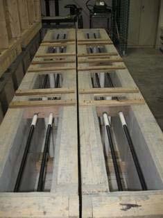
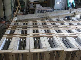
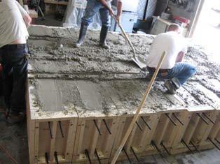
23 Construction of Test Slabs
24 Schematic of Test Slabs SECTION - AA Concrete Slab (Typ.) Crack Initiator (Typ.) PVC Pipe (Typ.) Treated Rad (Typ.) A Treated Rad (Typ.) Crack Initiator (Typ.) A PVC Pipe (Typ.) Concrete Slab 2'X10'X9" Treated Rad (Typ.)
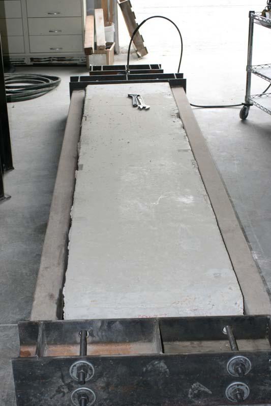
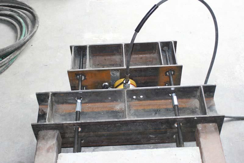
25 Tensioning of Test Slabs
26 Schematic of Test Slabs Cracked TENCION FORCE Force SECTION - AA Concrete Slab (Typ.) Crack Initiator (Typ.) PVC Pipe (Typ.) Treated Rad (Typ.) A Treated Rad (Typ.) Crack Initiator (Typ.) A PVC Pipe (Typ.) TENCION FORCE Force Treated Rad (Typ.) Concrete Slab 2'X10'X9"


27 Controlled Cracked Uncracked Slab Cracked Slab
28 NCPTC 2009 study* 1/3 depth saw cut Average Cracking time: 0.2 to 2.2 days Strain in concrete at the crack time: 6.6 µε µε 1/4 depth saw cut Average Cracking time: 0.2 to 6.5 days Strain in concrete at the crack time: 23.5 µε µε Early Age saw cut Average Cracking time: 1.4 to 24.1 days Strain in concrete at the crack time: 22.8 µε µε National Concrete Pavement Technology Center, Center for Transportation Research and Education, Iowa State University Crack Development in Ternary Mix Concrete Utilizing Various Saw Depths, February 2009
29 Calculated Strain in Concrete Test Slabs Pmax = 50K Diameter of Steel Rod = ¾ in. Stress(steel) = 37.5 ksi Strain(steel) = 1,300 µε Ratio: εsteel/εconcrete Calculated εconcrete = µε Uncracked at 120 days
30 Summary of Testing Results Shape of Initiator V Shape covering approx 60% of CSA ¼ in. to 1.5 in. thickness Square/circular shape initiator covering approx % of CSA, ¼ in. to 1.5 in. thickness Rectangular shape with rounded edges initiator covering 10-20% of CSA, ¼ in. to 3 /8 in. thickness Number Tested Results 60 Slabs Crack at initiator, in. pretty straight 60 Slabs Crack at initiator to 0.01 in. cracking at surface 200+ Slabs Crack at initiator in. cracking at surface Comments Cracking very predictable Cracking controlled. 3 /8 in. thickness yield highly predictable results Cracking controlled ¼ to 3 /8 in. thickness yield highly predictable results up to 120 days after placement
31 Initiator Shape Factors Different crack initiator shape factors Initial versions were utilized using a V shape factor, maximizing the area of separation around the simulated dowel bar Testing has allowed revision of the shape factor to efficiently and effectively maximize the influence of the separation to allow for a controlled cracking end result circular, square and rectangular. Research also noted that the shape of the initiator affects the predictable behavior of the crack and is key in reducing the variability associated with cracking pattern. Surface area of the initiator ranged initially from 60%/ln section down to 16.5 %/ln section (conventional saw cutting reduces cross sectional area by 25% to 33%, early entry saw cutting reduces cross sectional area by 12% ) Thickness of the initiator affects cracking predictability
32 Pavement Critical Stressing Area Critical Stressing Area - Critical Stressing Area is the remaining concrete section. In a 10 in slab, the critical stressing area is reduced by 30% Current standard of practice is to - reduce the overall area by 1 in. deep or ¼ d or 1/3 d. - difficult to predict overall cracking behavior affected by slab restrained conditions C L 1" Deep Saw Cut C L 2 1 2" to 3" Deep Saw Cut 1Dowel 4" Ø Dowel Bar Bar 1Dowel 4" Ø Dowel Bar Bar 10" 10" Crack Initiator Crack Crack With Initiator Conv. Saw Cutting
33 Pavement Critical Stressing Area Critical Surface Area Governing area is typically the shortest distance within the weakened zone Initiators reduces the critical surface area to the area between the bottom of the saw cut and the top of the initiator, as oppose to the bottom of the saw cut to the bottom of the slab Initiator influences the cracking behavior making it more predictable C L 1" Deep Saw Cut 1Dowel 4" Ø Dowel Bar Bar C L 2 1 2" to 3" Deep Saw Cut 1 Dowel 4" Ø Dowel Bar Bar 10" 10" Crack Initiator Crack With Initiator Crack Conv. Saw Cutting
34 Location of Initiator Location of initiators Bottom of the test slabs - reduction in critical stressing area, minimum effects noted. - Alignment of slab reduction saw cut and initiator is critical - Overall size had to be greater. Middle of the test slabs - reduction in critical stressing area. The location provides a break within the slab, thereby minimizing the critical stressing area factor. - greater effect on crack behavior prediction - alignment of saw cut and initiator is minimized - critical section is between the top of the initiator and the bottom of the surface separation 10" C L 1" Deep Saw Cut 1Dowel 4" Ø Dowel Bar Bar Crack Initiator Crack
35 Overall Pavement Surface Reduction Surface Reduction at the Top Separation at the top of the slabs, in line with the initiator, were made with different depths with the shallowest being 1/8 in. deep. Crack formation was noted at the bottom of the separation. Initiator increases the influence of the reduced surface, with the area between the bottom of the reduced surface and the top of the initiator being the governing factor A 1 in. deep saw cut would be more than sufficient to include the cracking propagation attributes in the PCC pavement
36 Timing Slabs have been stored up to 120 days after placement and tensioned to obtain crack at the predicted location Slabs cracked only at the initiators Slabs cracked when the strain in the concrete reached 130 to 160 µε
37 Surface Reduction Alignment Current standard practice of saw cutting does not have adequate controls to always predict the crack path especially in longitudinal translation cases. With regularly spaced initiators and with the weakest link principal, the crack will occur at the weakest link, shortest possible distance. If the reduction in area within a slab is not immediately at the center of the initiator, the crack will originate from the reduction in area within the slab and will run along side of the initiator Crack in concrete is influenced by the reduction in the overall cross sectional area With initiators in place, the initiator influences the overall pattern of the crack above the dowel bar. Without the initiator, the crack path is unpredictable. Restrain conditions can affect the crack propagation below the dowel bar C L 1" Deep Saw Cut Dowel Bar 1 1 4" Ø Dowel Bar C L 2 1 2" to 3" Deep Saw Cut 1 4" Ø Dowel Bar Dowel Bar 10" 10" With Initiator Crack Initiator Crack Crack Saw Cutting
38 Stresses Concentration on Dowel Bar Stresses on dowel bar are highest at the top and bottom of the dowel bar Sides of the dowel bar do not aid in shear stress distribution from the concrete Smaller diameter bars result in higher stress concentration on the top and bottom of the dowel bar 1 Top of Slab Bottom of Slab Load Stress Concentration Region Dowel 1 4" Ø Dowel Bar Bar Neutral Region 1. Center for Transportation Research and Education, Dowel Bar Optimization: Phase I and II, Final Report Oct. 2001
39 Design of Initiator Design Considerations Shape Factor Size of Initiator Location of Initiator Easy to install on dowel bar Steady Smooth Overall shape factor and weight affecting transportation of baskets Number of Initiator Needed based on overall surface reduction

40 Design of Initiator Designed to be welded to the dowel bar Initiator is designed not to influence the stacking of the dowel bar Gaps in the initiator to reduce weight Welded at neutral stress zone on the dowel bar Rounded edges Smooth face Dowel Bar
41 Design of Initiator Thickness: ¼ in. to 3 /8 in. thick Number of Initiators: between dowel bars Recommended Surface Reduction: 1 in. Depth of Initiator: Slab Depth Up to Initiator Thickness ¼ in. Depth of Initiators 2 in. 1 ¼ to 1 ½ Dia Dowel Bar 10 in. > 10 in. ¼ in. to 3 /8 in. thick 2.5 in.
42 Predictability of Cracking With Initiator Saw Cut Timing Early Conv. Cracking Predicted With Initiator 66% 70% 85% Net Area Based upon a 10 in. Thick Slab
43 SUMMARY Increase cracking predictability. In order to influence the cracking formation, a small separation at the top of the PCC pavement is needed. The depth of separation can be minimized to an inch or less to allow for a visually pleasing appearance Utilizes current saw cutting methods Location of the initiator inline with the dowel bar maximizes the influence on the location of the crack The initiator influences the behavior of the crack predictable cracking behavior Overall thickness of separation can be 1 /4 to 3 /8 inch wide slab depth dependant The initiator provides a discontinuity within the PCC pavement. The initiator reduces the critical stressing area to form the crack area above the initiator The ability to control cracking characteristics. The precise location (longitudinal translation approx 1 in.) of the saw cut becomes a little less critical. May influence the saw cutting window Provide savings through better performance of the pavement slab

44 QUESTIONS? Better Performance Through Innovative Designs
45 Contact Info: Malcolm K. Lim, PE LimCMT, Inc. 109 Bernard Drive Buffalo Grove, IL E: P: Better Performance Through Innovative Designs
46
Dowel Bar Alignment and Location for Placement by Mechanical Dowel Bar Insertion
 Dowel Bar Alignment and Location for Placement by Mechanical Dowel Bar Insertion January 7, 2013 Scope, Background and Applicability This guide specification is directly applicable to 18 in. (457 mm) long,
Double Bar Plate Dowels for Saw-Cut Contraction Joints
 Double Bar Plate Dowels for Saw-Cut Contraction Joints Designed to Deliver More Serviceable Slabs Concrete slabs-on-ground must be able to withstand the repetitious, concentrated loads and abrasion of
TECHNICAL MANUAL. TERADOWEL and ULTRADOWEL. Reliable Dowel System for Floor Joints
 TECHNICAL MANUAL TERADOWEL and ULTRADOWEL Reliable Dowel System for Floor Joints Version: PEIKKO GROUP 11/2018 TERADOWEL and ULTRADOWEL Reliable Dowel System for Floor Joints Dowels manufactured from high
R&T UPDATE. An Alternative to Traditional Round Dowel Bars Plate Dowel Innovations Driven by Industrial Concrete Paving
 R&T UPDATE Concrete Pavement Research & Technology An Alternative to Traditional Round Dowel Bars Plate Dowel Innovations Driven by Industrial Concrete Paving #9.02 Introduction Round dowel bars have long
ABCDE. TechBrief. Best Practices for Dowel Placement Tolerances
 TechBrief The Concrete Pavement Technology Program (CPTP) is an integrated, national effort to improve the long-term performance and cost-effectiveness of concrete pavements. Managed by the Federal Highway
AMENDMENTS Manual of STANDARD SPECIFICATIONS. Adopted by Standard Specifications Committee. Amendment. No. 6. Published by
 AMENDMENTS to 2012 Manual of STANDARD SPECIFICATIONS Adopted by Standard Specifications Committee Amendment No. 6 Published by Utah LTAP Center Utah State University 8305 Old Main Hill Logan UT 84322-8205
Flanged Dowel Box. Load Transfer System INDUSTRIAL SLAB ON GROUND
 Flanged Dowel Box INDUSTRIAL SLAB ON GROUND Designed for construction joints in Post Tension or large shrinkage specifications Large lateral movement and expansion capacity Eliminates the need to drill
PD 3 Dowel Cradle. Load Transfer System Industrial Slab on Ground
 PD 3 Dowel Cradle Industrial Slab on Ground Provides the flattest joints Assists in reducing long term maintenance costs Extends the life-cycle of the floor and the asset Engineered to meet Super Flat
Dowels for the 21st Century
 Dowels for the 21st Century by Wayne W. Walker and Jerry A. Holland sing plate dowels in slabs on ground for shear load transfer at the joints offer many advantages over the traditional round dowels. By
PERFORM WITH PRECISION WELDED DOWEL ASSEMBLY LOAD TRANSFER PRODUCTS CONCRETE CONSTRUCTION SOLUTIONS BROCHURE
 WELDED DOWEL ASSEMBLY LOAD TRANSFER PRODUCTS PERFORM WITH PRECISION CONCRETE CONSTRUCTION SOLUTIONS BROCHURE Transfers Loads for Pavement Durability Today the modern Portland Cement Concrete pavements
Dowel. Design. Performance-Based World of Concrete Official Show Issue. Lift-truck design changes require a new look at joint durability
 2007 World of Concrete Official Show Issue January 2007 Performance-Based Dowel Lift-truck design changes require a new look at joint durability Design By Wayne W. Walker and Jerry A. Holland S erviceability
Evaluation of Dowel Bar Inserter Practices in PCC Pavements with Magnetic Tomography Technology
 University of Nebraska - Lincoln DigitalCommons@University of Nebraska - Lincoln Nebraska Department of Transportation Research Reports Nebraska LTAP 12-2016 Evaluation of Dowel Bar Inserter Practices
Table 5G-2.01: Transverse Joint Requirements. Transverse Joint Type 6 C 12 7 C 15 8 CD CD CD 1 20
 Design Manual Chapter 5 - Roadway Design 5G - PCC Pavement Joints 5G-2 Types of Joints A. Jointing PCC pavement joints are necessary primarily to control the location of cracks that occur from natural
Design and Construction of Highway Pavement Joint Systems
 Design and Construction of Highway Pavement Joint Systems Troubleshooting Joint Design and Construction Issues Mark B. Snyder, Ph.D., P.E. Engineering Consultant to the American Concrete Pavement Association
² TL Beton-StB 07 = German technical conditions for construction materials for concrete road pavements
 Introduction A transverse joint frequently crossed by heavy goods traffic tends to form steps if it not perfectly doweled. This is associated with negative effects on ride comfort and driving safety as
Dowel Alignment Considerations and Specification Update
 Dowel Alignment Considerations and Specification Update November 8, 2016 Mark B. Snyder, Ph.D., P.E. American Concrete Pavement Association Staff Consultant Presentation Overview What are the sources of
The Need for Improved Specifications on Dowel Bar Placement Tolerance
 Yu and Tayabji 1 The Need for Improved Specifications on Dowel Bar Placement Tolerance H. Thomas Yu (tyu@ctlgroup.com) Shiraz D. Tayabji (stayabji@ctlgroup.com) CTLGroup 9030 Red Branch RD, Suite 110 Columbia,
Design and Construction of Highway Pavement Joint Systems
 Design and Construction of Highway Pavement Joint Systems Dowel and Tie Bar Design Considerations Part 2 Mark B. Snyder, Ph.D., P.E. Engineering Consultant to the American Concrete Pavement Association
Diamond Dowel. Load Transfer System INDUSTRIAL SLAB ON GROUND
 Diamond Dowel INDUSTRIAL SLAB ON GROUND Diamond Dowel designed for construction joints Tapered plate design allows for diagonal shrinkage Eliminates the need to drill or process formwork Design ensures
Glulam Connection Details
 T E C H N I C A L N O T E Glulam Connection Details Note: This version is superseded by a more current edition. Check the current edition for updated design and application recommendations. ENGINEERED
Mark B. Snyder, Ph.D., P.E.
 ACPA s New Dowel Alignment Specification Mark B. Snyder, Ph.D., P.E. Vice-President, ACPA Pennsylvania Chapter Presentation Sources: Robert Rodden, ACPA National Tom Yu, FHWA Dowel baskets Improper handling
Dowel Alignment: Measurement and Impacts on Pavement Performance
 Dowel Alignment: Measurement and Impacts on Pavement Performance prepared by: Mark B. Snyder, Ph.D., P.E. Vice-President, ACPA-PA Chapter for: ACPA s 2012 Annual Meeting Concrete Pavement University November
Session 8: Load Transfer Restoration. (Dowel Bar Retrofit, Cross-Stitching, and Slot Stitching)
") Session 8: Load Transfer Restoration (Dowel Bar Retrofit, Cross-Stitching, and Slot Stitching) Learning Outcomes 1. List benefits and applications of dowel bar retrofit (DBR), cross stitching, and slot
Session 8: Load Transfer Restoration (Dowel Bar Retrofit, Cross-Stitching, and Slot Stitching) Learning Outcomes 1. List benefits and applications of dowel bar retrofit (DBR), cross stitching, and slot
Section 914. JOINT AND WATERPROOFING MATERIALS
 914.01 Section 914. JOINT AND WATERPROOFING MATERIALS 914.01. General Requirements. Joint and waterproofing material for use in concrete construction must meet the requirements of this section. 914.02.
Plate Dowels. An Innovation Driven by Industrial Concrete Paving. Introduction
 Plate Dowels An Innovation Driven by Industrial Concrete Paving Introduction Round steel dowel bars have long been the standard load transfer device for concrete pavements with thicknesses of about 8 in.
Dowel Bar Alignment and Location for Placement by Mechanical Dowel Bar Insertion
 Dowel Bar Alignment and Location for Placement by Mechanical Dowel Bar Insertion Scope, Background and Applicability August 14, 2013 This guide specification is directly applicable i to 18 in. (457 mm)
Design of structural connections for precast concrete buildings
 BE2008 Encontro Nacional Betão Estrutural 2008 Guimarães 5, 6, 7 de Novembro de 2008 Design of structural connections for precast concrete buildings Björn Engström 1 ABSTRACT A proper design of structural
Why Do We Saw Equipment Types Matching Equipment to the Project Blade Selection Ensuring Construction Quality When Things Don t Go Right The Sawing
 Why Do We Saw Equipment Types Matching Equipment to the Project Blade Selection Ensuring Construction Quality When Things Don t Go Right The Sawing Window Summary Controlled Cracking Uncontrolled Cracking
Jointing Rural Intersections
 Design Manual Chapter 5 - Roadway Design 5G - PCC Pavement Joints 5G-4 Jointing Rural Intersections This section describes how to joint rural intersections by following the guidelines outlined in Iowa
KANSAS DEPARTMENT OF TRANSPORTATION SPECIAL PROVISION TO THE STANDARD SPECIFICATIONS, 2007 EDITION
 Sheet 1 of 7 KANSAS DEPARTMENT OF TRANSPORTATION SPECIAL PROVISION TO THE STANDARD SPECIFICATIONS, 2007 EDITION SECTION 502 PORTLAND CEMENT CONCRETE PAVEMENT (NON-QC/QA) Page 500-20, subsection 502.2.
MIT Product Demonstration
 MIT Product Demonstration ACPA 55 th Annual Meeting CPU 4 Presented by Garry Aicken, P.E. North American Distributor for MIT Demonstrate the New Rail Less Dowel Bar Scanner - MIT-DOWEL-SCAN Demonstrate
JVI Vector Connector
 The JVI Vector Connector User Guidelines 1 of 11 INTRODUCTION JVI designed the Vector Connector for use as shear and alignment connections between precast concrete elements such as double-tee flanges,
ESR-1799 Reissued April 2014 This report is subject to renewal June 1, 2015.
 ICC-ES Evaluation Report www.icc-es.org (800) 42-6587 (562) 699-054 ESR-799 Reissued April 204 This report is subject to renewal June, 205. A Subsidiary of the International Code Council DIVISION: 0 00
4.1. Foremen 4.2. Concrete plant manager 4.3. Concrete plant operator 4.4. Personnel performing saw cutting and joint sealing
 10-1. JOINTED PLAIN CONCRETE PAVEMENT GENERAL Summary This work includes constructing jointed plain concrete pavement. Comply with Section 40, "Concrete Pavement," of the Standard Specifications. Submittals
A Solution to Cracking and Stresses Caused by Dowels and Tie Bars
 Square bars and a special clip-on plastic sheath solve the problem A Solution to Cracking and Stresses Caused by Dowels and Tie Bars by Ernest K. Schrader D owels and tie-bars are important to the design
ICC-ES Evaluation Report Reissued June 1, 2011 This report is subject to renewal in one year.
 ICC-ES Evaluation Report www.icc-es.org (800) 42-658 (562) 699-054 ESR-99* Reissued June, 20 This report is subject to renewal in one year. A Subsidiary of the International Code Council DIVISION: 0 00
TECHNICAL MANUAL. OPTIMAJOINT Free Movement Joint. Free Movement Joint System for Heavy Traffic
 TECHNICAL MANUAL OPTIMAJOINT Free Movement Joint Free Movement Joint System for Heavy Traffic Version: PEIKKO GROUP 12/2018 OPTIMAJOINT Free Movement Joint Free Movement Joint System for heavy traffic
Plate 60 ArmourMate. Joint Edge Protection INDUSTRIAL SLAB ON GROUND. Plate 60 AmourMate. Joint Edge Protection
 Plate 60 AmourMate Plate 60 ArmourMate INDUSTRIAL SLAB ON GROUND Accommodates large concrete shrinkage Facilities thermal movement Prevents spalling on construction joints Extends the life-cycle of the
Precast Concrete Pavement Background Concepts. Project 1517 FHWA, CTR & TxDOT Gary Graham November 15, 2001
 Precast Concrete Pavement Background Concepts Project 1517 FHWA, CTR & TxDOT Gary Graham November 15, 2001 Project Background CTR contracted by FHWA/TxDOT to investigate the feasibility of using precast
Unit IV Drawing of rods, wires and tubes
 Introduction Unit IV Drawing of rods, wires and tubes Drawing is a process in which the material is pulled through a die by means of a tensile force. Usually the constant cross section is circular (bar,
Hyper ArmourMate. Joint Edge Protection INDUSTRIAL SLAB ON GROUND
 Hyper ArmourMate INDUSTRIAL SLAB ON GROUND Full system edge protection Prevents concrete spalling at construction joints High FF and FL tolerances Extends the life-cycle of the floor and the asset Provides
ESR-1799 Reissued June 1, 2009 This report is subject to re-examination in one year.
 ICC-ES Evaluation Report ESR-799 Reissued June, 009 This report is subject to re-examination in one year. www.icc-es.org (800) -87 () 99-0 A Subsidiary of the International Code Council DIVISION: 0CONCRETE
SOFF-CUT EARLY ENTRY SAWING. Ben Pevreall
 SOFF-CUT EARLY ENTRY SAWING Ben Pevreall Manufacturing Footprint - Machines Huskvarna, Swe ~ 100 empl. Xiamen, China ~100 empl. Åsbro, Swe ~ 20 empl. Olathe, KS, USA ~ 50 empl. Manufacturing Footprint
IGGA Guide Specification: Dowel Bar Retrofit (DBR) Introduction
 Introduction") IGGA Guide Specification: Dowel Bar Retrofit (DBR) Introduction This standard developed by the International Grooving and Grinding Association (IGGA) specifies the procedures for construction of dowel
IGGA Guide Specification: Dowel Bar Retrofit (DBR) Introduction This standard developed by the International Grooving and Grinding Association (IGGA) specifies the procedures for construction of dowel
ESR-2024* Reissued September 1, 2011 This report is subject to renewal September 1, 2013.
 ICC-ES Evaluation Report ESR-2024* Reissued September, 20 This report is subject to renewal September, 20. www.icc-es.org (800) 42-68 (62) 699-04 A Subsidiary of the International Code Council DIVISION:
SPECIFICATIONS FOR THE MANUFACTURE AND DESIGN OF PRECAST THREE SIDED ARCH STRUCTURES, WINGWALLS AND HEADWALLS
 SPECIFICATIONS FOR THE MANUFACTURE AND DESIGN OF PRECAST THREE SIDED ARCH STRUCTURES, WINGWALLS AND HEADWALLS 1. DESCRIPTION THESE SPECIFICATIONS ARE FOR A PRECAST THREE SIDED ARCH STRUCTURE, HEADWALLS
Evaluation of In-Pavement Light Fixture Designs and Performance
 Evaluation of In-Pavement Light Fixture Designs and Performance Presented to: IES ALC Fall Technology Meeting By: Joseph Breen Date: Background In-Pavement Light Fixture Assemblies Utilize a Circle of
Magnetic Imaging Technology
 Magnetic Imaging Technology 200 Virginia Concrete Conference H. Thomas Yu State of the Practice " The importance of proper dowel alignment is widely recognized, but it could not be verified effectively
Module 10 : Improvement of rock mass responses. Content
 IMPROVEMENT OF ROCK MASS RESPONSES Content 10.1 INTRODUCTION 10.2 ROCK REINFORCEMENT Rock bolts, dowels and anchors 10.3 ROCK BOLTING MECHANICS Suspension theory Beam building theory Keying theory 10.4
Corso di Studi di Fabbricazione
 Corso di Studi di Fabbricazione 3a Richiami dei processi tecnologici di trasformazione FUNDAMENTAL OF METAL FORMING 1 METAL FORMING Large group of manufacturing processes in which plastic deformation is
Connection and Tension Member Design
 Connection and Tension Member Design Notation: A = area (net = with holes, bearing = in contact, etc...) Ae = effective net area found from the product of the net area An by the shear lag factor U Ab =
Module 3 Selection of Manufacturing Processes
 Module 3 Selection of Manufacturing Processes Lecture 4 Design for Sheet Metal Forming Processes Instructional objectives By the end of this lecture, the student will learn the principles of several sheet
State-of-the-art Report On FULL-DEPTH PRECAST CONCRETE BRIDGE DECK PANELS (SOA )
") State-of-the-art Report On FULL-DEPTH PRECAST CONCRETE BRIDGE DECK PANELS (SOA -01-1911) Vince Campbell Former president of Bayshore Concrete Products Corporation, VA This presentation is developed
State-of-the-art Report On FULL-DEPTH PRECAST CONCRETE BRIDGE DECK PANELS (SOA -01-1911) Vince Campbell Former president of Bayshore Concrete Products Corporation, VA This presentation is developed
Please do not open this exam until you are told to do so.
 Seat # Name a General examination rules: 1) Do not put your completed work anywhere that it can be seen. If any part of your work can be seen by others it will be confiscated and you will not be permitted
Dowel Basket Standardization
 Dowel Basket Standardization National Concrete Consortium San Antonio, TX March 31, 2009 John F. Staton Michigan DOT Summary of Dowel Basket Standardization Activities 2000 to Present Spring 2000 - Initial
Tool 3-1 A2 Bushing 6 Check if the bushing supports (angle iron) are properly welded with the upper part of the structure pipes. welded bushing suppor
 are properly welded with the upper part of the structure pipes. welded bushing suppor") Rope Pump MANUFACTURING checklist for quality control A Welding General 1 Check if welding jigs are used for welding of the main parts (wheel, structure frame and bushings) 2 Check if the pump parts are
Rope Pump MANUFACTURING checklist for quality control A Welding General 1 Check if welding jigs are used for welding of the main parts (wheel, structure frame and bushings) 2 Check if the pump parts are
Alternative Dowel Bars
 Alternative Dowel Bars Max L. Porter Department of Civil, Construction and Environmental Engineering Iowa State University Ames, IA 50011-3232 mporter@iastate.edu ABSTRACT Alternative dowel bars for joints
ICC-ES Evaluation Report Reissued March 1, 2011 This report is subject to renewal in two years.
 ICC-ES Evaluation Report www.icc-es.org (800) -68 (6) 699-0 ESR-8* Reissued March, 0 This report is subject to renewal in two years. A Subsidiary of the International Code Council DIVISION: 0 00 00 CONCRETE
Midwest Roadside Safety Facility
 19'-11 1/2" 6083 239'-11 1/2" 73139 Impact 1100C 25 43 5/16" 1100 upstream from the upstream face of the first shear fender downstream of the joint between barrier nos. 7 and 8 Upstream End Downstream
INGAA Foundation Workshop - Industry Initiatives Regarding Welding of Field Segmented Induction Bends and Elbows for Pipeline Construction
 INGAA Foundation Workshop - Industry Initiatives Regarding Welding of Field Segmented Induction Bends and Elbows for Pipeline Construction October 20, 2011 Steve Rapp, P.E. Spectra Energy Transmission
Chapter VI Vessel Supports
 Chapter VI Vessel Supports 1 2 Vessel Supports Vessel support is to a. Support the weight of the container b. Fix the container position c. Keep the container in operation. Classified by the type of vessels:
Dowel connections in laminated strand lumber
 Dowel connections in laminated strand lumber Cranswick, Chad J. 1, M c Gregor, Stuart I. 2 ABSTRACT Laminated strand lumber (LSL) is a relatively new structural composite lumber. As such, very limited
Load application in load cells - Tips for users
 Load application in load cells - Tips for users Correct load application on the load cells is a prerequisite for precise weighing results. Be it load direction, support structure or mounting aids load
CITY OF LOS ANGELES CALIFORNIA
 BOARD OF BUILDING AND SAFETY COMMISSIONERS JAVIER NUÑEZ PRESIDENT MARSHA L. BROWN VICE-PRESIDENT VAN AMBATIELOS PEDRO BIRBA ELENORE A. WILLIAMS CITY OF LOS ANGELES CALIFORNIA ANTONIO R. VILLARAIGOSA MAYOR
FRAMELESS GLASS FENCING DIY GUIDE
 FRAMELESS GLASS FENCING SITE MEASURE 1. Planning is the first step of any successful project. 2. We have a large range of sizes to allow for varying site requirements. 3. Simply decide where you would
CE2045-PREFABRICATED STRUCTURES QUESTION BANK
 CE2045-PREFABRICATED STRUCTURES QUESTION BANK UNIT I - INTRODUCTION PART A 1. Define prefabrication 2. What are the types of prefabricates based on i. Plan area ii Based on weight 3. What are the types
Drilled Rail Lubrication
 APTA Rail Conference June 23, 2015 SKF Lincoln Lubrication Systems St Louis, MO Presented by Drew Welch Completed by Paul Conley Drew Welch SKF North American Railroad Specialist Drew Welch is the North
Skewed connections result when members frame to each
 Design of Skewed Connections LARRY KLOIBER and WILLIAM THORNTON ABSTRACT Skewed connections result when members frame to each other at an angle other than 90º. This paper provides some guidance in the
Drawing. Fig. 1 Drawing
 Drawing Drawing is a metalworking process which uses tensile forces to stretch metal. It is broken up into two types: sheet metal drawing and wire, bar, and tube drawing. The specific definition for sheet
EXTERIOR BUILDING, ROOFING, AND SITE IMPROVEMENTS
 CONTRACT NUMBER: IFB-8-B006 ARCHITECT / ENGINEER : HURST-ROSCHE, INC. NO. LINOIS 62203 (68) 398-0890 -7 E. RANDLE ST./ N. FRITZ ST. 402 CHERRY ST., 404-406 ST. LOUIS ST. 502-506 DEE ST. 50-505 PLUM ST.
EPS Allowable Stress Calculations (Rev. 2)
") EPS - LDS Calculations - Brigham City Page 1 EPS Allowable Stress Calculations (Rev. 2) 8:11 AM Required Calculate the vertical stress in the top of the EPS block from the live loads (traffic load) for
EPS - LDS Calculations - Brigham City Page 1 EPS Allowable Stress Calculations (Rev. 2) 8:11 AM Required Calculate the vertical stress in the top of the EPS block from the live loads (traffic load) for
Anti-check bolts as means of repair for damaged split ring connections
 Anti-check bolts as means of repair for damaged split ring connections Quenneville, J.H.P. 1 and Mohammad, M. 2 ABSTRACT There are numerous large span timber hangars dating back to the Second World War.
Wire and pipe drawing
 Wire and pipe drawing Overview Wire drawing application deformations, drawing speeds and forces equipmentm dies and die materials Tube drawing tube drawing processes Strain and drawing force Drawing tools
Shear force transmission in expansion joints
 for better solutions Shear dowel Shear force transmission in expansion joints Reliable expansion joint dowelling in concrete structural elements General Single shear dowel HED Expansion joint dowelling
Hours / 100 Marks Seat No.
 17610 15116 4 Hours / 100 Seat No. Instructions (1) All Questions are Compulsory. (2) Answer each next main Question on a new page. (3) Illustrate your answers with neat sketches wherever necessary. (4)
Effect of Dowel Bar Embedment Length on Joint Load Transfer Efficiency of MnROAD Concrete Pavement Test Cells
 Effect of Dowel Bar Embedment Length on Joint Load Transfer Efficiency of MnROAD Concrete Pavement Test Cells Thomas R. Burnham, P.E. Abstract It is well understood that for heavily loaded concrete pavements,
PCCP Preservation Steps to Take to Extend Pavement Life and Performance of Your Concrete Pavements
 PCCP Preservation Steps to Take to Extend Pavement Life and Performance of Your Concrete Pavements Larry Scofield, P.E. International Grooving and Grinding Association 1 Big Preservation Everybody Wins
KAERI Feeder Tube Inspection Using EMAT Generated Circumferential Guided Waves
 Sonic Sensors www.sonicsensors.com 1of 9 KAERI Feeder Tube Inspection Using EMAT Generated Circumferential Guided Waves Objective: Inspection of small diameter pie with complex curves. The principal defects
Jointed Precast Concrete Pavement
 NATIONAL PRECAST CONCRETE ASSOCIATION Manual for Jointed Precast Concrete Pavement 3rd Edition Authors Peter Smith, P.E. Mark B. Snyder, Ph.D., P.E. Graphic Designer Deborah Templeton NPCA Precast Concrete
Glass Fiber Reinforced Polymer (GFRP) Dowel Bars - Aslan 600
 Dowel Bars - Aslan 600") Glass Fiber Reinforced Polymer (GFRP) Dowel Bars - Aslan 600 August 16, 2011 Aslan 600 Glass FRP Dowel Bars are used as a Load Transfer device between joints in concrete slabs. They provide a mechanical
Glass Fiber Reinforced Polymer (GFRP) Dowel Bars - Aslan 600 August 16, 2011 Aslan 600 Glass FRP Dowel Bars are used as a Load Transfer device between joints in concrete slabs. They provide a mechanical
HOLLOW CORE PRODUCTS GROUNDED IN STRENGTH
 HOLLOW CORE PRODUCTS GROUNDED IN STRENGTH usable space under your garage 8 form - 8 Hollow Core 7' - 11-1/2" 3" min. topping for precast diaphragms 2-3/ 3" MIN. TOPPING FOR PRECAST DIAPHRAGMS 7' - 11-3/4"
1. Enumerate the most commonly used engineering materials and state some important properties and their engineering applications.
 Code No: R05310305 Set No. 1 III B.Tech I Semester Regular Examinations, November 2008 DESIGN OF MACHINE MEMBERS-I ( Common to Mechanical Engineering and Production Engineering) Time: 3 hours Max Marks:
Sheet Metal Forming. Part 1
 Sheet Metal Forming Part 1 Sheet Metal Forming For products with versatile shapes and lightweight Dates to 5000 B.C. Products include metal desks, file cabinets, appliances, car bodies, beverage cans Common
Corrosion-Resistant Coated Dowel Bars
 Standard Specification for Corrosion-Resistant Coated Dowel Bars AASHTO Designation: M 254-06 (2010) American Association of State Highway and Transportation Officials 444 North Capitol Street N.W., Suite
See Detail C 1. 30'' Long Tie Bar. at 12'' Centers 'DW' 3. Pavement Edge. 24'' min. Plastic or Tarpaper Wrapped. Header Block
 See Detail C See dowel assemblies for fabrication details. '' PIN JOIN (butting Pavement Slabs) 0 ong ie ar at Centers 'DW' DY'S WORK JOIN(Non-working) 7 See ar Size able. ocate 'DW' joint at a mid-panel
A Tale of Tearouts: Web Supplement
 A Tale of Tearouts: Web Supplement This is a supplement to the May 2017 Modern Steel Construction article A Tale of Tearouts (available at www.modernsteel.com/archives). The information presented here
Research A PERFORMANCE TESTING OF EXPERIMENTAL DOWEL BAR RETROFIT DESIGNS PART 1 INITIAL TESTING. Final Report
 2004-17A Final Report PERFORMANCE TESTING OF EXPERIMENTAL DOWEL BAR RETROFIT DESIGNS PART 1 INITIAL TESTING Research Technical Report Documentation Page 1. Report No. 2. 3. Recipients Accession No. MN/RC-
Permanent fasteners: Riveted joints Welded joints Detachable joints: Threaded fasteners screws, bolts and nuts, studs. Cotter joints Knuckle joints
 Instructional Objectives At the end of this lesson, the students should have the knowledge of Fasteners and their types: permanent and detachable fasteners. Different types of pin joints. Different types
SUMMARY SHEETS OF BAR COUPLER CONNECTIONS
 APPENDIX A SUMMARY SHEETS OF BAR COUPLER CONNECTIONS NCHRP 12 88 Connection Evaluations Appendix A A 1 APPENDIX A SUMMARY SHEETS OF BAR COUPLER CONNECTIONS NCHRP 12 88 Connection Evaluations Appendix
PENSTOCK CONDITION ASSESSMENT
 Northwest Hydro Association May 17, 2012 Technical Seminar PENSTOCK CONDITION ASSESSMENT Thomas L. Kahl, P.E. Kleinschmidt TOPICS Concerns Types of Penstock Failure Modes Steel and Wood Stave Failure Mode
Mechanical behavior of fiberglass reinforced timber joints
 Mechanical behavior of fiberglass reinforced timber joints Chen, Chi-Jen 1 ABSTRACT The objective of this research is to investigate the mechanical performance of dowel-type timber joints reinforced by
STRUCTURAL ATTACHMENTS
 Brace Structural Attachment Selection Procedure ) Determine structure to be attached to from the following: A) Concrete B) Wood Beam C) Structural Steel 2) Reference structure connection type from Appendix
Responses to Concrete Specifications Survey with Summary (2011)
") Responses to Concrete Specifications Survey with Summary (2011) In March of 2011, a survey was sent out by Manitoba Infrastructure and Transportation (MIT) Materials Engineering Branch to poll Department
Responses to Concrete Specifications Survey with Summary (2011) In March of 2011, a survey was sent out by Manitoba Infrastructure and Transportation (MIT) Materials Engineering Branch to poll Department
MANUFACTURING TECHNOLOGY
 MANUFACTURING TECHNOLOGY UNIT II SHEET METAL FORMING PROCESSES Sheet metal Process in detail Cutting (Shearing) Operations Manufacturing Technology In this operation, the work piece is stressed beyond
CONCRETE MANHOLES.
 CONCRETE CONCRETE SHAW PIPE produces circular, precast, concrete manholes in diameters 1050mmØ through 3000mmØ. Precast, concrete manholes are most frequently used for pipeline and sewer entry and are
Prying of a Large Span Base Plate Undergoing a Moment Load Applied by a Round Pier
 Prying of a Large Span Base Plate Undergoing a Moment Load Applied by a Round Pier by Anastasia Wickeler A thesis submitted in conformity with the requirements for the degree of Masters of Applied Science
SMAW LESSON #1: Initiating and maintaining an arc using the scratch start method
 SMAW LESSON #1: Initiating and maintaining an arc using the scratch start method OBJECTIVE: Upon completion of this lesson the learner will be able to strike and maintain an arc using SMAW on steel plate
Bar, Wire and tube drawing
 Bar, Wire and tube drawing R. Chandramouli Associate Dean-Research SASTRA University, Thanjavur-613 401 Joint Initiative of IITs and IISc Funded by MHRD Page 1 of 8 Table of Contents 1.Analysis of wire
Pipe Product Catalog Table of Contents
 Pipe Product Catalog Table of Contents Section A: Drawing #: Page Description A1 Reinforced Concrete Pipe A3 Storm Manhole Sizing Chart (48" - 96") A3.1 Storm Manhole Sizing Chart (108" - 144") A4 48"
Construction of Steel Penstocks using HT100 at Kannagawa Hydropower Plant
 Construction of Steel Penstocks using HT100 at Kannagawa Hydropower Plant Ken-ichiro AOKI 1 and Masayuki MINAMI 1 1 Tokyo Electric Power Company, Japan Introduction Tokyo Electric Power Company s Kannagawa