A Flying Belanca Aircruiser How You Can Build a Flying Scale Model of a Famous Cargo Plane That Includes Many Fine Details of Construction
|
|
|
- Dwight Warner
- 5 years ago
- Views:
Transcription


 The ship weighs 6115 pounds when empty and is capable of carrying a pay load of 4021 pounds.")
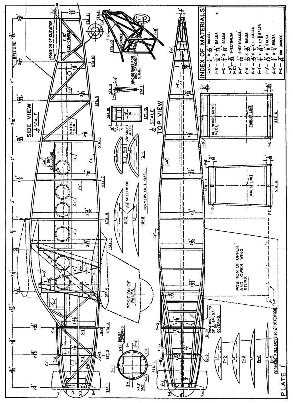
1 It performs well with a flying propeller The finished model with scale propeller A Flying Belanca Aircruiser How You Can Build a Flying Scale Model of a Famous Cargo Plane That Includes Many Fine Details of Construction By JOSEPH KOVEL The completed uncovered framework indicates close adherence to the large plane design Embodying many realistic details of the full scale plane, it provides a real thrill when is flight An actual photograph of the model in full light THE Bellanca Aircruiser Cargo Landplane, to give it its full title, was designed and built for transport work. Modern transport needs require ships that are fast, economical, yet capable of carrying high pay loads. The Bellanca Aircruiser meets these requirements very nicely. Its single engine and cruising range of 1000 miles assure economy. The high speed of the ship at 7000 ft. is 165 miles per hour, while the cruising speed is 155 miles per hour. (Imagine a freight train cruising at that speed!) The ship weighs 6115 pounds when empty and is capable of carrying a pay load of 4021 pounds. This high weight pay load ratio may be attributed to the unusual design of the ship. Note that the wing struts serve not only to brace the wing structure, but also contribute to the lift of the ship. This two purpose design of the strut results in a considerable saving in weight, which is
2 reflected in the weight-lifting ability of the ship. This ship is well adapted for model work. The long nose moment allows the model to be built with a natural balance - that is - the finished model will not require any additional weight in the nose to balance it (providing of course, that you use the proper grade of materials.) This eliminates dead weight, which detracts from the efficiency of the ship. This model is very stable due to the large dihedral angle formed by each lower wing stub and the lifting strut. Two other important factors that contribute to the stability of the ship are that the center of lateral area is almost exactly on the thrust line, while the center of gravity is slightly below the thrust line. The cathedral angle, formed by the lower wing stubs and the bottom of the fuselage, permits easy landings, due to the cushioning effect of this arrangement. Not only is the model a good flyer, but it also looks good, as you may judge from the accompanying photographs. Following is the suggested procedure for building the model: General Instructions Study the drawings and read the instructions before starting actual work on the ship. Strive for accuracy and neatness of workmanship. When building the ship, be sure to use the grade of materials specified as this has a great deal to do with the balance of the finished model. Sand each piece of wood that goes into the model. This will remove the "whiskers" which have no structural strength, yet burden the ship with useless weight. Fuselage In order to build the fuselage, you'll have to round up a soft board (about 8" x 24"), some drawing paper, pins and some wax paper, or better yet, a wax candle. Tack the drawing paper to the board and lay out the fuselage side. You do this by drawing the base line of the fuselage about one inch from the long edge of the board, then dropping a perpendicular from that line about 2" from the left side of the board. This perpendicular to the base line will determine the position of Station 1. Drop the perpendiculars from the base line that will determine the positions of the other 10 Stations (Plate 1-Side View). From the base line, measure down on each perpendicular the distance indicated on the plan, and make a dot there. When you have done this to all eleven perpendiculars, connect the dots, using the same curve as shown on plan. Thus you have the top outline of the fuselage side. To obtain the bottom outline, measure down on each perpendicular the distance indicated on the side view of the plan, plus 3/16" and make a dot there. (The dimensions given between the top and bottom longerons are for the vertical struts only). In order to get the bottom outline of the fuselage, we must add the top and bottom longeron thicknesses, 3/32" + 3/32", to the vertical strut dimensions. Hence the "plus 3/16"! When this has been done to all eleven stations, connect the dots, using the same curve as shown on plan. Now that you have the top and bottom outlines of the fuselage side, draw the various vertical and diagonal struts into place and you are ready to start work on the model. (Note! The portholes are put into place after the two sides have been assembled.) Either lay a sheet of wax paper over the drawing, or else rub the drawing with the wax candle previously mentioned. This will prevent the "work" from sticking to the drawing as you cement each joint. Make a pin jig for the fuselage side by pushing pins on each side of each longeron at strategic positions. As you cut either a longeron or strut to size for the right side of the fuselage, make an exact duplicate of that part for the left side and lay it aside until you have finished the first side and taken it out of the jig. All you have to do to make the second side is to assemble the parts you have made previously. This process makes it possible to get the two fuselage sides exactly alike. The longerons and struts are made of 3/32" sq. medium hard balsa, sanded smooth. The struts at Station 1 are 3/32" x 1/4" medium hard balsa. Set the longerons into the pin jig, then fit and glue into place all of the vertical and diagonal struts except those at Stations 4 and 5. Make a metal or hardwood wing rib template and another template for the bottom wing-stub rib. Using these templates, make 2 ribs of each kind, using medium soft 3/32" thick balsa. Shape these ribs to fit against the fuselage longerons as shown in Side View, Plate 1, then glue them into position. You can now cement the struts for Stations 4 and 5 into place. Make an elevator rib template and using it as a pattern, shape the 3/32" x 1/4" medium balsa strip that is used for the elevator cradle, then cement it into place. When you have the two fuselage sides done, assemble them as shown in Top View, Plate 1, taking care to square the job up right. Note Station 4, 5, 10 and 11 details. The fuselage formers are made of medium soft balsa. After you have shaped them and cemented them into place, the stringers 1-B, made of 1/16" sq. medium balsa, are assembled into position. Make the porthole frames 1-F, using 1/32" sheet balsa, medium grade. The windows should be made of a light grade of celluloid, cut just 1/16" larger in radius than the openings for the portholes (see drawing), then cemented to the side of the porthole frame which is to face the interior of the fuselage. Glue the completed porthole frames into place. The windows for the pilot's compartment may be covered with either light celluloid or cellophane. The next step is to make the motorstick (Plate 6). First make a "square" which is to fit into the nose of the ship (1/16" x 1/4" medium balsa). Select a light piece of balsa for the nose block (1-3/8" sq. x 1/2") and cement it firmly to the "square." When this is dry, fit the "square" into the nose of the fuselage, carve and sand the block to the correct shape. (If you intend making a scale prop for your model, make two of these nose-plug units, one for the flying prop and one for the scale prop.) The motorstick is made of 3/16" x 1/4" x 17-5/8" hard balsa. Sand this stick, then give it a couple of coats of dope, which will serve to strengthen it. Cut a small section out of the "square" and make a hole through the nose block as shown on plan, then push the motor-stick into place and cement it there. The prop bearing consists of an eyelet glued to the front of the nose block and a washer at the rear of the block. The rear hook is made of.032 music wire. Should your motor-stick bend excessively when the rubber motor is
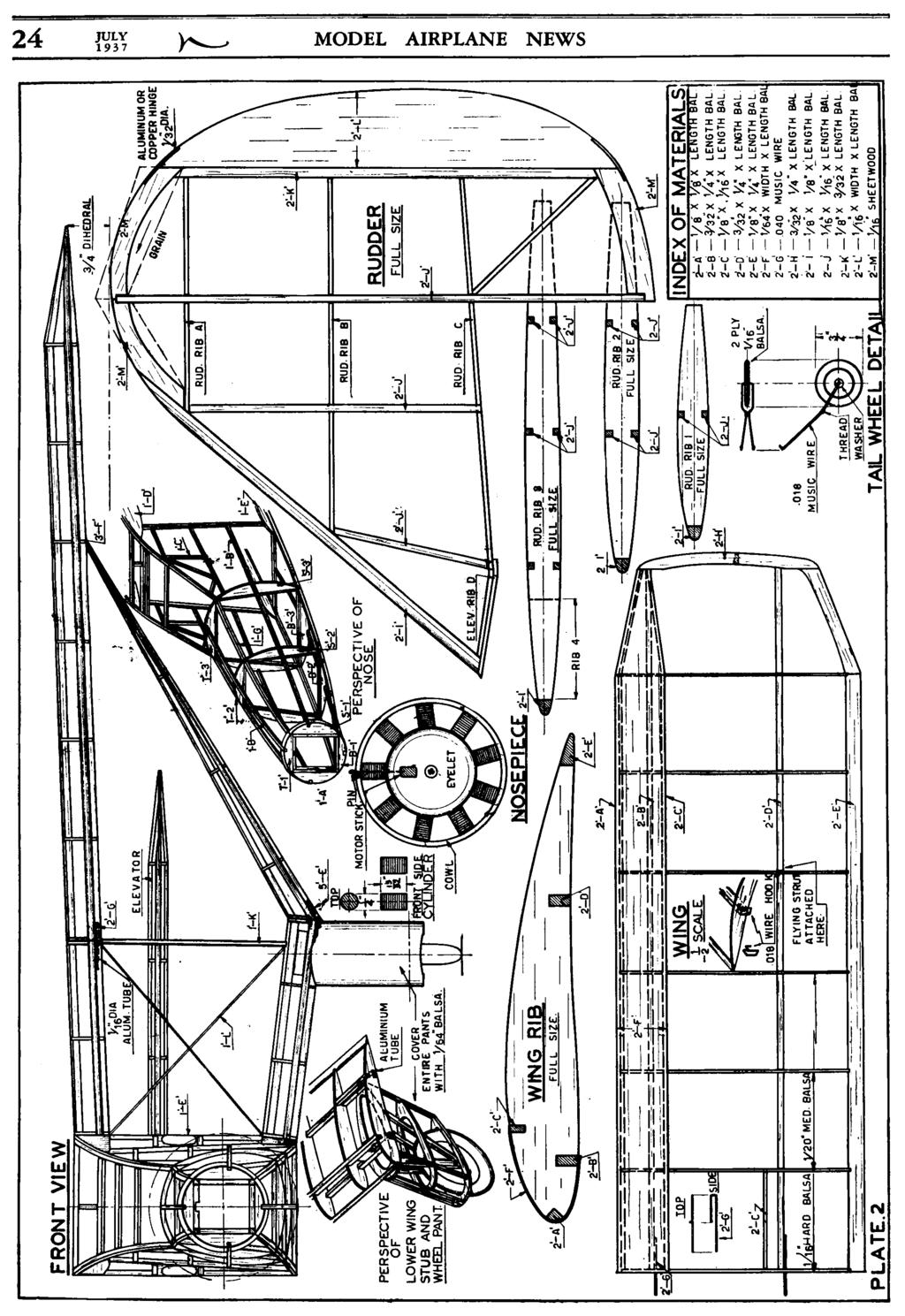
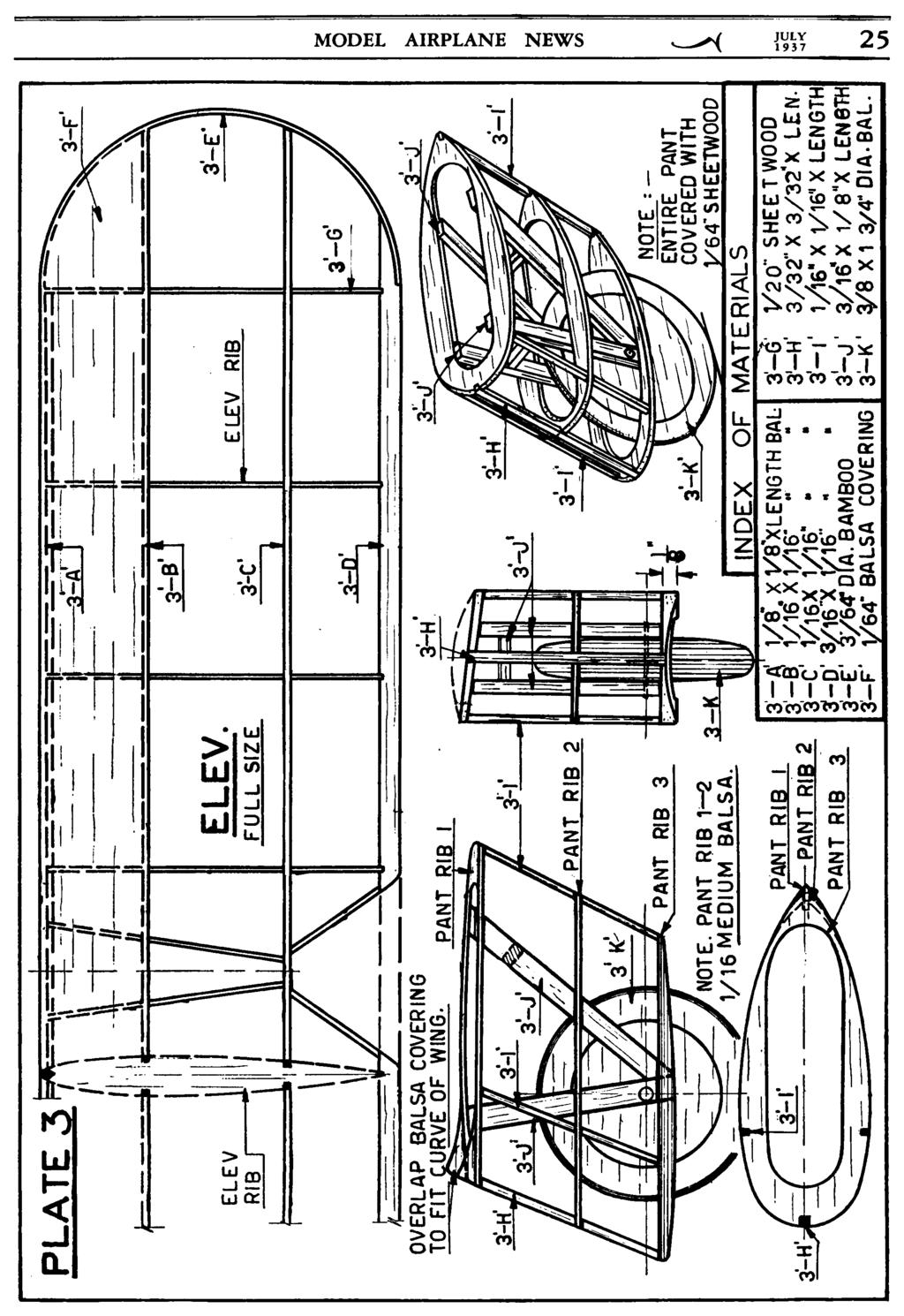
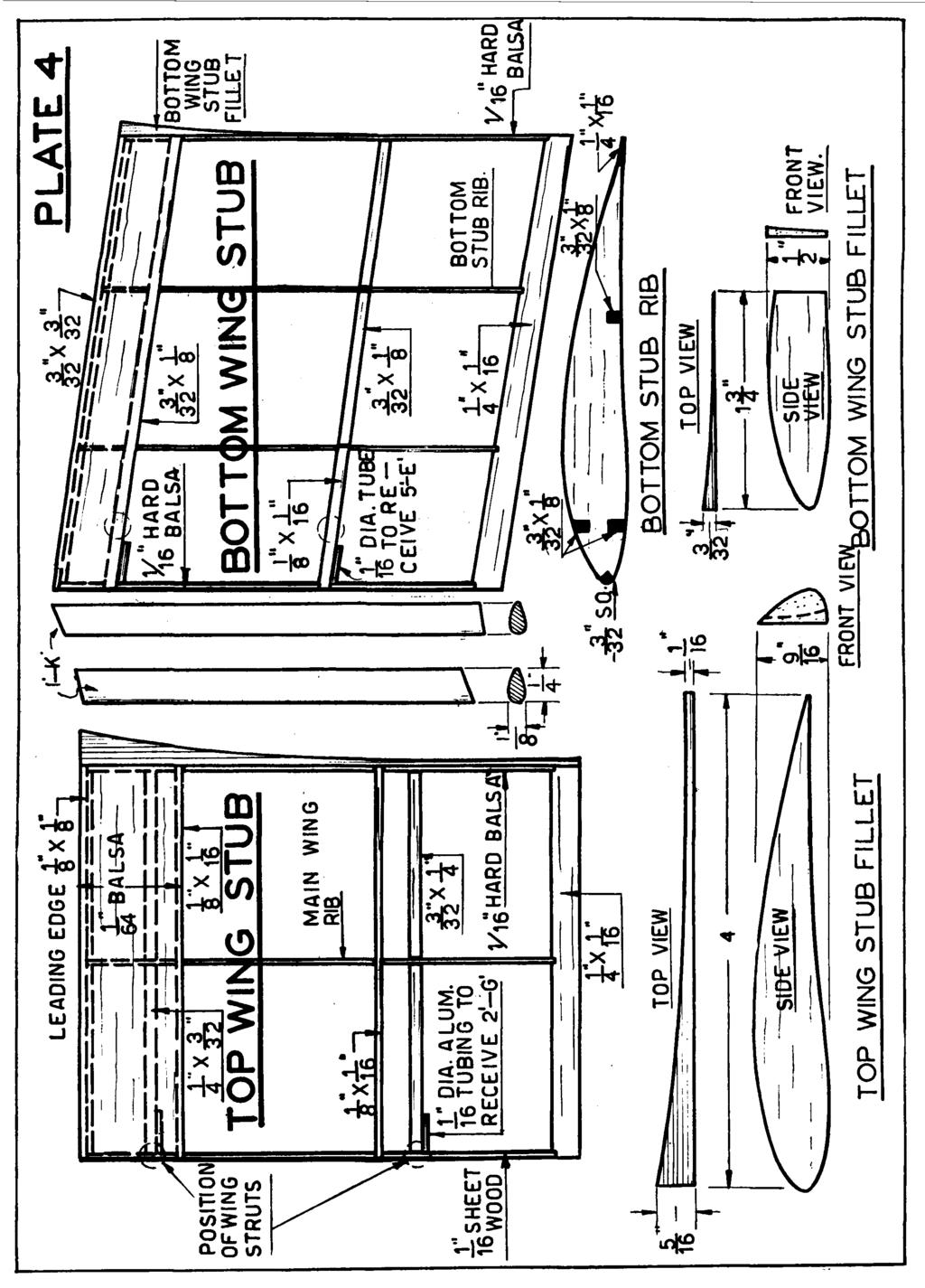
3 tightly wound, make a wire can (.028 music wire) and cement it to the center of the motor-stick. Now that you have the motor-stick finished, you can cover the nose of the fuselage with 1/64" medium soft balsa. The top of the fuselage is covered as far as Station 3, while the bottom and sides are covered as far as Station 4. The tail-wheel is made of 1/8" medium balsa (Two 1/16" sheets glued together cross-grained) and has a washer cemented to each side of the hub. The wire fitting (Plate 2) is made of.018 music wire. Cement the unit to the fuselage as shown in the perspective detail on Plate 1. Check the glue joints of the fuselage and reinforce all those that may need it with another coat of cement. Tail Frames Using the rib template you made for shaping the elevator cradle for the fuselage, make 10 elevator ribs, using medium balsa 1/ 20" thick. Notch the ribs as shown (Plate 3), then make the leading edge (medium balsa), the spars (hard balsa) and the trailing edge (hard balsa). Mark the position of the ribs on the leading edge and the trailing edge, then make 1/32" notches in the trailing edge to receive the ribs. Start assembling the frame by cementing the ribs to the leading and trailing edge. (Note - the trailing edge is kept in one piece until the entire frame is finished - after which the center section is cut away for the rudder clearance.) Cement the spars into place. The tips are made by bending a 3/64" x 1/4" strip of bamboo to shape over a candle or other flame, then splitting off a couple of 3/64" strips and rounding them. After the tips are glued into place, cut away the center section of the trailing edge as mentioned above, then cover the leading section of the elevator with 1/64" med. soft sheet balsa. The rudder (Plate 2) is made using the same procedure as for the elevator. The controlling flap is fastened into place by means of a piece of aluminum or copper wire 1/32" dia., which is glued into place as shown on plan. Main Wings (Plate 2) The main wing is made in the same manner as the elevator. The leading edge, spars, tip and 1/20" thick ribs are all made of medium balsa, while the 1/16" end rib and the trailing edge are made of hard balsa. After the main wing frames are done, cover the leading sections with 1/64" thick medium soft balsa, then glue wire fittings 2-G and the flying strut attachment hook into place. Top and Bottom Wing Stubs (Plate 4) The top and bottom wing stubs are also made in the same manner as the elevator except that the bottom stubs have a false spar just over the rear spar at the end section adjoining the flying strut. There is a filler block between the false top and the bottom spars which serves to transmit the landing shock to struts 1-K, and so up to the main wing. (See Front View, Plate 2). To make the stub fillets, cement the blocks to the ends of the wing stubs first, then shape them as shown on plan. Glue the 1 /16" aluminum tubes to the spars, then check their position by sliding the main wing into place and seeing that it lines up all right. Flying Struts (Plate 5) The flying struts are also similar in construction to the elevator. Note that the end rib is set at an angle. Cement wire fitting, 5-E into place. (Fitting 5-F is cemented into place as the ship is assembled. Landing Gear (Plate 3) Make pant ribs 1, 2 and 3 using a medium grade of balsa. Assemble each pant as shown in Side View, making one left and one right. Note that the top rib is set at an angle so as to conform with the wing stub angle (see Front View - - Plate 2). Make the landing struts 3-J. Glue the front and rear struts together, forming a "V" as shown in the Side View. Cement a washer to each side of the front strut, then glue each "V" into the pant frame as shown in the perspective view. Cement the cross-brace into place. Note that the tops of the "V" struts are flush with the top of the rib. The wheels are made of 3-ply balsa (three 1/8" sheets of medium balsa glued together crossgrained). Cement a washer to each side of the wheel hub, then paint the "tire" black and the center orange (or any other color you may prefer). After the wheels have been painted, put them into position between the "V" struts of the landing gear, pass a pin thru the struts and wheel, then cement the pin into place. Covering Cover the fuselage with blue tissue, then spray it with water. After it has dried, give it two coats of clear dope. Using some light writing paper, cut out 12 circular rims, having an O.D. of 9/16" and an I.D. of 5/8 ", and cement one to each porthole. (See accompanying photographs). Using the same type of paper, cut some strips 1/16" wide and cement them around the front windows. The elevator, main wings, top and bottom wing stubs and the flying struts are covered with yellow tissue, and treated the same way (water sprayed, then two coats clear dope). The rudder may be entirely covered with yellow tissue, or if you wish to have army rudder bars on it, cover the part forward of the main spar with yellow tissue, and the part rear of the main spar with white tissue. Cut some 1/4" wide strips of red tissue and dope them to the white tissue of the rudder at 1/4" intervals, parallel to the ribs, then dope a strip of blue tissue about 3/8" wide just over the main spar. Assembly Cement the elevator into its cradle at the rear of the fuselage, then glue the rudder into place. Take care to line them up properly. Join the main wing and the upper wing stub as shown in Front View, Plate 2, using a drop of cement at the leading and trailing edge of the joint. Now, using a table or any other cleared surface, we'll make an assembly jig. This is done by laying the fuselage on the table and propping up the rear end so that it is in flying position. Put a small weight on top of the fuselage to prevent its moving around. Cement each wing half to the corresponding fuselage side, putting books or something else under each wing tip to keep it in position until the glue has hardened. Check the dihedral angle, the angle of incidence of each wing half (making sure that both halves have the same amount of incidence)
4 and the alignment of the wing to the fuselage. Take the ship out of the jig, cement the lower wing stubs to the fuselage, then glue the struts 1-K into place. Join the flying struts to the lower wing stubs and note the position to which the wire hooks 5-F should be cemented to the flying struts in order to preserve the proper alignment of the surfaces. When you have determined the proper positions for these hooks, disjoin the flying struts from the lower wing stubs and cement the hooks into place. When the glue has hardened, engage the hooks at the ends of the flying struts with the hooks in the wing, then once more join the flying struts with the lower wing stubs, putting a drop of cement at the leading and trailing edges of the joints. Cement each pant unit to its corresponding lower wing stub so that the front struts of the "V" braces anchor to the front spar of the lower wing stub and the rear struts of the "V" braces anchor to the rear spars of the wing stub. Now cover each pant frame with 1/64" thick medium light balsa, then cover the unit with blue tissue. Cement the bamboo struts 1-L into place, after having painted them silver. The cylinders are made of 1/4" balsa dowel with black thread wrapped and cemented around it to simulate the cooling fins. Cut these cylinders to size and cement them to the nose of the ship as shown on Plate 2. The anti-drag ring (Plate 5) is made of either balsa or a light grade of cardboard. The cardboard is preferred in this case as it will bend easily and symmetrically without cracking, as the balsa would tend to do. After you have bent the ring to shape and cemented the joint, put it around the cylinders and see that it fits right. After you've checked the fit, dope some orange tissue to the inside and outside of the ring. This will both strengthen and decorate it. Fit the ring over the cylinders and cement it into place. Propellers (Plate 6) The flying prop is made of medium balsa. Join the blades as shown on drawing, then when the glue joint has hardened, carve the concave face of the blades. When this has been done, shape the blades as shown, then carve the convex face of the blades. The next job is to balance the prop. Push a pin through the hub of the prop, then, holding the protruding end of the pin with one hand, spin the prop over with the other hand. If it turns over evenly and comes to rest smoothly, the prop is balanced, but if it turns over jerkily and one of the blades causes a pendulum-like action just before coming to a rest pointing towards the ground, you'll have to sand that heavy blade and repeat the tests until the prop balances perfectly. Give it two coats of clear dope and two coats of silver dope. Sand lightly between coats. The last coat is not sanded, but left natural. Push the prop shaft through the rear of the nose plug, slip a few washers on the shaft, put the prop on the shaft, bend the end of the shaft to a "U" shape, and pull the shaft back so that the "U" sinks into the prop hub. Cement it firmly into place. (While making the flying prop, it is advisable to make the scale prop. You will note how much more realistic the ship looks with the scale prop than with the flying prop. When you're not fling the ship, you can take out the motor-stick with the flying prop and put the nose-plug with the scale prop on it and you have an attractive exhibition model.) Slip 4 strands of 3/16" flat rubber on the rear-hook and prop shaft, put the motor-stick unit into the fuselage, and anchor it into place by pushing a pin through the anti-drag ring, top cylinder, and into the motor-stick (see Nosepiece Detail, Plate 2). The ship is now ready for the test hop. Balance the ship by holding the wing with your index fingers about 1/3 back of the leading edge. The model should balance on an even keel. If it is tail heavy, add a bit of weight to the nose. If it is nose heavy, add weight to the tail. When the ship has been balanced, wind the prop about 75 turns by hand, raise the nose of the ship slightly and launch the ship. If the model has been built properly, it will make a fairly long gliding flight to the ground for a graceful landing. If the ship stalls, raise the leading edge of the elevator slightly. If the ship dives, raise the trailing edge of the elevator slightly. If it banks excessively, wash-in the low banking wing, wash-out the high banking wing, and give the ship some opposite rudder if necessary. When the ship has been adjusted properly, remove the motor-stick from the fuselage, lubricate the rubber motor, attach an "S" hook to the rear of the rubber motor, hook the "S" hook to a mechanical winder, stretch the motor to about 4 times its normal length, and then give it as many winds as it will safely hold. Put the motor-stick back into the fuselage, pin it into place, then launch the ship on its maiden flight to the heavens. You'll get a big kick out of watching the smooth and graceful flight action of the ship, and the dignified attitude with which it comes in for a landing. A free-wheeling device on the prop will tend to flatten the glide of the ship. Scanned from July 1937 Model Airplane News
5
6
7
8
9
10
A large prop insures high performance. Cleverly designed to give a realistic appearance
 Cleverly designed to give a realistic appearance A large prop insures high performance A Vought Fighter That Flies Complete Data from Which You Can Build an Excellent Performing Flying Scale Model of the
The model boasts of twin fuselages and three fins
 An Experimental Twin Tractor One of the Most Unique and Finest Fliers Ever Presented. If You Want Something Different, Build and Fly This One By FELIX GUTMANN The model boasts of twin fuselages and three
STRATOSPHERE CONTEST MODEL
 STRATOSPHERE CONTEST MODEL A Super-Duration Fuselage Plane With Extremely High Power-Weight Ratio It Has Made a Flight of Thirty- Five Minutes Construction of the light hut strong frame work is simple
Build and Fly This Bristol Fighter
 Build and Fly This Bristol Fighter How You Can Build a Simplified Flying Scale Model of One of the Greatest British World War Planes By LAWRENCE McCREADY The finished model looks like the real thing Though
Building a WorId Record Fuselage Model
 Building a WorId Record Fuselage Model How You Can Build and Fly the Model With Which the Author Established a World's Record of 41 Minutes and 19 Seconds By WILLIAM YING The finished model ready to fly
Building the Fairchild "24" by JOSEPH S. OTT Model Editor
 Building the Fairchild "24" by JOSEPH S. OTT Model Editor The completed Fairchild "24" is the most faithful copy of the full size machine that has yet been produced. Showing the undersurfaces and the structure
THE DUCK BY LOUIS GARAMI A rubber-powered amphibian.
 THE DUCK BY LOUIS GARAMI A rubber-powered amphibian. The Duck takes off easily from water. The landing gear folds upward for water flying, is locked in place by rubber band. Right-The ship is light but
A Flying Grumman Fighter How You Can Build a Model of One of the Latest U.S. Navy Fighters That Is an Excellent Flier By WILLIAM WINTER
 A Flying Grumman Fighter How You Can Build a Model of One of the Latest U.S. Navy Fighters That Is an Excellent Flier By WILLIAM WINTER The completed model is faithful to scale and detail THE Grumman F3F-1
Bob Hildebrand s Kitten. The Kitten. By Bob Hildebrand
 Bob Hildebrand s Kitten The Kitten By Bob Hildebrand HERE S A 100 SQ. IN JOB WITH WAKEFIELD PERFORMANCE AYE there, laddie,,arre ye Scotch we' th' rubberrr? If you are the kind who doesn't appreciate the
THE CABINEER A new method for construction of monocoque fuselages -- a high-performance sportster. By LOUIS GARAMI
 THE CABINEER A new method for construction of monocoque fuselages -- a high-performance sportster. By LOUIS GARAMI The clean sweep of line, the plan form of the flying surfaces, and the neat monocoque
THE STREAMLINER! A super Class D fuselage model
 THE STREAMLINER! A super Class D fuselage model by CHRISTIAN D. BERGER THE two most important characteristics of a contest model are its climb, and gliding ability. For, after all, you have to get up high
A Class A Gas Model That Looks Like a Full Scale Plane and Performs Like a Contest Ship
 A Class A Gas Model That Looks Like a Full Scale Plane and Performs Like a Contest Ship By SAL TAIBI 1941 NATIONAL WINNER The little plane glides in with all the realism of a full scale craft The plans
Nick Limber s Debby. Debby Gas Job *** *** By Nick Limber
 DON T SKIP THIS Debby Gas Job *** HERE'S ANOTHER SMOOTH LITTLE GAS BUGGY FROM NICK LIMBER DRAWING BOARD. ALL YOU LADS WHO HAVE BUILT NICK'S SLEEK SHIPS KNOW THEY'RE TOP-NOTCH, AND WON'T WANT TO PASS THIS
THE PRIVATEER. A Class B job that performs well with both small and intermediate bore engines. By BEN SHERESHAW
 THE PRIVATEER A Class B job that performs well with both small and intermediate bore engines. By BEN SHERESHAW A baby streamliner, rugged and efficient. For this type of model the construction is not complicated.
Building A Flying Curtiss "Osprey" How You Can Create One of the Finest Flying Scale Models You Have Ever Built
 Building A Flying Curtiss "Osprey" How You Can Create One of the Finest Flying Scale Models You Have Ever Built By WILLIAM WINTER Though of biplane type it has excellent flying qualities THE OSPREY, an
By ROBERT VAIL SMITH. A clean streamline job with a unique power plant. A speedy ship with tandem "props" revolving in opposite directions
 A speedy ship with tandem "props" revolving in opposite directions A clean streamline job with a unique power plant The Koolhoven "Pursuit" Unusual Looks and Flying Qualities Grace This Exact Scale Model
Build this little "Chihuahua" A miniature engine in a little ship... But the combination produces big time performance. by David D.
 Build this little "Chihuahua" A miniature engine in a little ship... But the combination produces big time performance. by David D. Grant Up and Atom! "Chihuahua" has a snappy climb. Small and compact,
A Flying Twin Motor DOUGLAS DB-7 A Realistic Model Bomber. This Is Easy to Build and Fly
 A Flying Twin Motor DOUGLAS DB-7 A Realistic Model Bomber. This Is Easy to Build and Fly By SIDNEY STRUHL A fine flyer; just like the full-size plane Twin motors give a long and steady flight The three-wheel
By Pvt. Ted Lanham COULD BE A FREE-FLIGHT JOB OR CONTROLLINER. THIS SEMI-SCALE CLASS B GASSIE HAS EYE-APPEAL, CONTEST-LIKE PERFORMANCE.
 By Pvt. Ted Lanham COULD BE A FREE-FLIGHT JOB OR CONTROLLINER. THIS SEMI-SCALE CLASS B GASSIE HAS EYE-APPEAL, CONTEST-LIKE PERFORMANCE. Rearwin Speedster was used as basis for this design. Model, ready
FOCKE - WULF STOSSER
 FOCKE - WULF STOSSER Complete plans and directions for building a high performance miniature of a world-famous German sportster. By PAUL PLECAN and ROGER HAMMER The framework of the model is distinctive.
Nationals Flying Scale "Champ" Not Only National Winner but a Realistic Plane That Flies Two Minutes Consistently By HENRY STRUCK
 The little "big" plane that won at the 1941 Nationals, with its striking appearance and performance. Nationals Flying Scale "Champ" Not Only National Winner but a Realistic Plane That Flies Two Minutes
Building the T-D Coupe
 Efficient because of excellent streamlining The finished plane is extremely realistic Building the T-D Coupe A Sleek Gas Job That Is Simple To Build and Noted for Consistent Flights By THEODORE DYKZEUL
COMET 24" HELLCAT REPRODUCTION ASSEMBLY GUIDE
 COMET 24" HELLCAT REPRODUCTION A RUBBER POWERED 24" WING SPAN MODEL BY PAUL BRADLEY ASSEMBLY GUIDE AUGUST 2016 CHANGES MADE TO THE ORIGINAL The following changes were made to the original Comet kit structural
An All-Balsa Sportster
 An All-Balsa Sportster A REMARKABLE FLIER OF UNIQUE DESIGN THAT WILL GIVE YOU MANY ENJOYABLE BUILDING AND FLYING HOURS By STAN D. MARSH Contributions by Felix Gutmann This model was designed primarily
The Baby Duration Trainer
 The Baby Duration Trainer Complete Data From Which You Can Build a Duration Trainer of 100 Sq. In. Wing Area or Contest Models of Larger Size By FELIX GILBERT The completed model gives high performance
Building A Baby Biplane
 Building A Baby Biplane A Simple Plane That Will Provide Worlds of Fun and Valuable Information for Beginner or Expert By ROBERT C. HARE The little plane in full flight The finished model is simple yet
The "Indoor Cabin" Nationals Winner BY HENRY STRUCK
 Two views of the little ship and the trophy it won The "Indoor Cabin" Nationals Winner BY HENRY STRUCK Struck winds motor out of plane. Ballas "holds" Struck hooks motor in fuselage by meansof "rod" shown
SPORTSTER BY FRED TUXWORTH
 SPORTSTER BY FRED TUXWORTH For those who like gas models to look like real airplanes, this sturdy performer is just about tops. Best -looking model of the year Biplane wings may be fitted. This gives you
BERRYLOID TROPHY WINNER
 BERRYLOID TROPHY WINNER An unusual gas model distinguished for its beautiful construction, finish, and stability. By HAROLD COOVERT Harold covert and his Berryloid Trophy Winner at Detroit, where the ship
C-180 Builder s Manual
 C-180 Builder s Manual. May 20, 2002 Last revised July 11, 2002 Copyright! 2002 Douglas Binder, Mountain Models www.mountainmodels.com sales@mountainmodels.com (719) 630-3186 1 Required Equipment! Xacto
Build and fly this exact scale 43-in. control-line version of the popular Cessna private plane.
 Seeing double? Clever photography gives that illusion but actually it s only the model 140 in the foreground. Author Stahl (right) does fly both the job he is holding and his real Cessna 14 pictured in
COMET SENIOR DART REPRODUCTION ASSEMBLY GUIDE
 COMET SENIOR DART REPRODUCTION A RUBBER POWERED 24" WING SPAN MODEL BY PAUL BRADLEY ASSEMBLY GUIDE JANUARY 2018 CHANGES MADE TO THE ORIGINAL The following changes were made to the original Comet kit structural
BUILDING THE FUSELAGE FRAME 6
 KIT 305 DHC-2 BEAVER COPYRIGHT 2011 BY PAUL K. GUILLOW, INC. WWW.GUILLOW.COM Before starting the construction of your model, study the plan and construction procedure carefully so that you will have a
THE SWALLOW. An interesting, simple, all-balsa speedster of crashproof design. by MALCOLM J. ABZUG
 THE SWALLOW An interesting, simple, all-balsa speedster of crashproof design. by MALCOLM J. ABZUG DESIGNED primarily for the purpose of testing a new type of monocoque fuselage design, the Swallow proved
Tough warrior. The author's many years of intensive competition are your guarantee of a sturdy, fliable design with all "bugs" eliminated.
 Tough warrior. The author's many years of intensive competition are your guarantee of a sturdy, fliable design with all "bugs" eliminated. LAST month we described the construction of the fuselage and motor
THE FLYING AIR WARDEN
 THE FLYING AIR WARDEN A high performance contest "C" gas model that looks like a real airplane by AL PARDOCCHI FOREWORD Al Pardocchi has produced some of the finest and most consistent planes ever built.
Your kit contains the following parts. Please check your kit for any missing or damaged parts before starting construction.
 Your kit contains the following parts Please check your kit for any missing or damaged parts before starting construction COMPLETE KIT PARTS LIST 1 Plan Sheet #1 1 Plan Sheet #2 2 Decal Sheet 2 White Tissue
THE RECORD HOUND BY HENRY STRUCK The ship that set a 1939 N. A. A. record during the winter with a three-flight average of 5:41!
 THE RECORD HOUND BY HENRY STRUCK The ship that set a 1939 N. A. A. record during the winter with a three-flight average of 5:41! Though inverted, engine is protected by wheel. Frontal area is small, engine
Fighting Sopwith Snipe
 Fighting Sopwith Snipe FAMOUS SNIPE IN MODEL FORM OFFERS DETAIL AND FLIGHT TO BUILDERS By Joseph H. Wherry YOU fellows who still enjoy building scale models of World War I aircraft will now be able to
THE APOGEE A 100-INCH AMA DURATION SAILPLANE FROM DYNAFLITE
 THE APOGEE A 100-INCH AMA DURATION SAILPLANE FROM DYNAFLITE Apogee is the intermediate sailplane designed to be competitive in AMA duration contests. Effective spoilers, rudder and full flying stabilizer
Citabria Pro. Aerobatic Parkflyer. by Joel Dirnberger
 Citabria Pro Aerobatic Parkflyer by Joel Dirnberger Revision C: December 21, 2004 Citabria Pro Building Instructions Length: Wingspan: Wing Area: Flying Weight: Wing Loading: Functions: Specifications:
FUSELAGE CONSTRUCTION
 FUSELAGE CONSTRUCTION Note: prior to building and gluing on the work surface use protective covering on your building surface. (wax paper or clear wrap) Fit the laser cut Fuselage Front and Fuselage Rear
By HARRY BARR... A cute little rubber job that is easy to build and fly. Full-size plans on next two pages.
 By HARRY BARR... A cute little rubber job that is easy to build and fly. Full-size plans on next two pages. "Hangar Rat" owes its existence to the "Sig Parasol," a simple, easy-to-fly, tissue-covered profile
The finished plane with a scale propeller, worthy of any builder.
 Building The Heinkel "Pursuit" By JESSE DAVIDSON How You Can Build a Carefully Detailed Flying Scale Model of a German War Plane That Has Gained Fame in Spain The finished plane with a scale propeller,
Here's a Little Gas Model that Has Every Desirable Quality - Small Span - Small Engine - Unusual Stability and a Big Performance By ELBERT J.
 Here's a Little Gas Model that Has Every Desirable Quality - Small Span - Small Engine - Unusual Stability and a Big Performance By ELBERT J. WEATHERS It has the appearance of a full scale ship It has
Cleveland Quickie Luscombe Silvaire
 Cleveland Quickie Luscombe Silvaire This plan package is not a 100% copy of the original kit. As you make your way through the instructions you will see the differences. Here s just a few of them: The
A Precision Contest Gas Job
 A Precision Contest Gas Job How You Can Construct a Small Realistic Gas Model That Has a Comparatively Slow Speed But High Consistent Performance By ELBERT J. WEATHERS Part No. 1 The miniature airplane
WRIGHT FLYER 1 INSTRUCTIONS FOR THE D10LC KIT
 WRIGHT FLYER 1 INSTRUCTIONS FOR THE D10LC KIT Manufactured in the USA by Easy Built Models PO Box 681744, Prattville, AL 36068-1744 Visit us at www.easybuiltmodels.com Easy Built Models GLUE METHODS Always
Easy Built Models Kit JX-02 MiG-15 Conversion to Rubber-Power By Matt Payne, October 2011
 Easy Built Models Kit JX-02 MiG-15 Conversion to Rubber-Power By Matt Payne, October 2011 The fuselage is restructured. The Jetex-related structural components, the stock keel parts, and the formers are
*** By Jesse Davidson
 SURPASSING ALL PREVIOUS PRODUCTIONS IN THE FAMOUS CURTISS HAWK PURSUIT CLASS, THE NEW HAWK 75 IS ONE OF THE MOST FORMIDABLE MILITARY SHIPS OF ITS TYPE EVER TO TAKE THE AIR. A WELLARMED, ALL-METAL LOW-WING
Piper Cherokee /3 scale. Construction Manual
 Piper Cherokee 140 1/3 scale Construction Manual STAB CONSTRUCTION 1. Remove foam cores from cradle and place on flat surface. Inspect pieces before you epoxy halves together making sure leading and trailing
THE FLYING SCALE NATIONALS WINNER
 THE FLYING SCALE NATIONALS WINNER By Henry Struck UNDER the rules governing the Flying Scale Event at the National Meet, a model to be eligible had to be an exact replica of a man-carrying machine every
SZD-10 bis CZAPLA ASSEMBLY MANUAL IN PICTURES
 1 RUDDER Plan and parts: 2 Assembly steps: Photo above: glue together rudder spar, ribs and trailing edge. Clamp spar to a flat surface (chipboard on the photo) and make sure the straight aligment of the
Fundamentals of Model Airplane Building
 The dihedral and sweepback give stability The finished glider ready to launch Fundamentals of Model Airplane Building A Complete Course for Beginners Who Wish to Become Expert. How to Build a Contest Glider-Part
RSM DISTRIBUTION Presents
 RSM DISTRIBUTION Presents MOSQUITO By Jack Sheeks Photo _ Jack Sheeks Semi Scale Twin Stunter Wing Span: 58" Length: 37-3/4 Area: 579 sq. in. Engine: Two.35 -.40 www.rsmdistribution.com Call (951) 678
LANDING GEAR. 1. Fit landing gear into slots on bottom of fuselage.
 LANDING GEAR 1. Fit landing gear into slots on bottom of fuselage. 4. Use channel-lock pliers to press blind nuts into position (note: drilled hole should be slightly smaller than shaft of blind nut for
BUILDING THE A6M2 ZERO
 BUILDING THE A6M2 ZERO Product Support (Do Not Remove From Department) TOP FLITE MODELS, INC CONGRATULATIONS' You now own the most accurate R/C Stand-Off Scale kit ever produced We at Top Flite hope that
ParkJet Builder s Manual
 ParkJet Builder s Manual Thank you for purchasing the ParkJet. The ParkJet is a profile ducted fan airplane that can be flown in a larger park. The ParkJet was initially designed by Scott Stoops and modified
E-AERO EPP PITTS KIT From BP HOBBIES. Parts Included in kit
 E-AERO EPP PITTS KIT From BP HOBBIES Parts Included in kit Thank you for purchasing the BP Hobbies/E-aero EPP Pitts. Please take the time to read through the instruction manual before beginning the build.
PITTS S2S CONSTRUCTION
 PITTS S2S CONSTRUCTION FUSELAGE CONSTRUCTION 1) Place the right fuselage side over the plan and mark the former positions. Place the left side over the right side and mark the former positions. Glue F1
JAMISON SPECIAL. Building Guide
 JAMISON SPECIAL Building Guide WING Mark then drill holes for wing jig rods. Slide Ribs onto jig rods Mark the rib positions on 1/16 x 1 trailing edge, 1/4 x 1/4 leading edge & 1/4 x 1/4 spars Pin ribs
Hobby Lobby Zip Supplementary instructions Please refer to the included drawings while using these assembly instructions
 Materials needed: 15 or 30 minute epoxy Medium CA Masking tape Scotch tape Servo Tape Wax paper Tools Needed: Pencil or marker Flat building surface Hobby knife or razor blade 7/64" or 3mm drill bit 3/16"
(Build Instructions)
") (Build Instructions) Specifications * Wingspan: 58cm * Length: 50cm * Flying Weight: 59 grams * Channels: 3 (Rudder Elevator Throttle) * Suggested Receiver: 4Ch Micro * Motor: 8mm GearDrive * Prop: GWS
(Build Instructions) Specifications * Wingspan: 58cm * Length: 50cm * Flying Weight: 59 grams * Channels: 3 (Rudder Elevator Throttle) * Suggested Receiver: 4Ch Micro * Motor: 8mm GearDrive * Prop: GWS
1/16" Square balsa strip stock is used for the fuselage and tail surfaces structure. 10T 11T 11B (2) 10B. Pec Bea. Wingspan - 18"
 10B. Pec Bea. Wingspan - 18") 1/16" Square balsa strip stock is used for the fuselage and tail surfaces structure. 10T 9T 8 11T 12 7T 6T F-1 7 11 (2) 10 9 6 13 Pec ea CAD Drawing by Paul radley Sheet 1 of 8 Nose plug is a lamination
1/16" Square balsa strip stock is used for the fuselage and tail surfaces structure. 10T 9T 8 11T 12 7T 6T F-1 7 11 (2) 10 9 6 13 Pec ea CAD Drawing by Paul radley Sheet 1 of 8 Nose plug is a lamination
84 WING SPAN MESSERSCHMITT BF-109
 84 WING SPAN MESSERSCHMITT BF-109 (COPYRIGHT PROTECTED 2014) ALL RIGHTS RESERVED MEISTER 84 ME-109 SIERRA GEAR UPDATE PLEASE NOTE: THE MAIN GEAR MOUNTING PLATE FROM SIERRA IS NOT SQUARE. YOU HAVE TO ROUND
Assembly Instructions
 Assembly Instructions Parts Included: 1 Nose Cone 1 Body Tube 3 1/8 Balsa Fins 1 Thrust Ring 1 Motor Tube 1 Motor Hook 1 Motor Sleeve 2 Centering Rings 1 Launch Lug 1 Kevlar Shock Cord (yellow) 1 Elastic
Test the pusher theory by building this Plane on the Cover model by EARL STAHL
 Test the pusher theory by building this Plane on the Cover model by EARL STAHL The search for superior fighting aircraft is an endless one for all warring nations. Constantly poring from engineers' drawing
Dandy Sport Builder s Manual
 Dandy Sport Builder s Manual Thank you for purchasing the Dandy Sport. The Dandy Sport has been designed as an easy to build aileron trainer. Take your time and enjoy building this plane. Specifications:
Note - the nose ribs and are thinner than the main ribs. These nose ribs will use a thinner rib cap than the ribs. This is per design.
 Stabilizer rev 1.2 The SE5a stabilizer is the heartbeat of the tail and is recreated like the full scale version. All tail pieces depend on the stabilizer. It uses the steel fittings, pulleys, inspection
4. Bevel the LE face of HS1-HS11 to match the horizontal stab leading edge sweep angle.
 BEFORE YOU BUILD 1. Unroll each sheet of the plans. Roll them inside out so that they will lie flat on the building surface. 2. Assemble the tools that you will need to build each section so that they
Curtiss XP-40Q Construction Notes
 Curtiss XP-40Q Construction Notes Thank you for purchasing this kit-we hope you will enjoy building and flying the last of the Curtiss P-40 series of fighter planes. Start construction by assembling the
96 WING SPAN SPITFIRE (COPYRIGHT PROTECTED 2014) ALL RIGHTS RESERVED
 ALL RIGHTS RESERVED") 96 WING SPAN SPITFIRE (COPYRIGHT PROTECTED 2014) ALL RIGHTS RESERVED GENERAL INSTRUCTIONS Should you elect to use the recommended Door Skin, which is 1/8 mahogany plywood measuring 36 x 88. Have it cut
96 WING SPAN SPITFIRE (COPYRIGHT PROTECTED 2014) ALL RIGHTS RESERVED GENERAL INSTRUCTIONS Should you elect to use the recommended Door Skin, which is 1/8 mahogany plywood measuring 36 x 88. Have it cut
Pfalz E1 Monoplane 48 EZ Build Version
 Pfalz E1 Monoplane 48 EZ BUILD Pfalz E1 Monoplane 48 EZ Build Version R/C Scale Model Instructions CONTACT INFORMATION Designed by M.K. Bengtson Prototype by Robert Hoffman Manufactured and Distributed
LARK. Classic Legal Precision Stunter RSM DISTRIBUTION. presents. Charles Mackey. Wing Area 570sq. Wingspan 52.
 RSM DISTRIBUTION presents LARK By Charles Mackey Photo _ Bob Hunt Classic Legal Precision Stunter Wingspan 52 Length 39.5 Wing Area 570sq Motor 35-46 www.rsmdistribution.com Page 2 Thank you for purchasing
Build the tail surfaces directly over the plans. Accurate joints will reduce warping problems when the tail is covered.
 General Notes Follow the plans carefully Study the written instructions as you build Even unusual jobs like mounting the 2ger's parasol wing are not difficult when each step is done carefully and in the
S.E.5a (Build Instructions)
") S.E.5a (Build Instructions) Specifications Wingspan: 38 cm Length: 31cm Flying Weight: 41 Channels: 3 (Rudder Elevator Throttle) Suggested Receiver: 3Ch Brick Motor: 7mm Geared Motor Airframe Only Kit
S.E.5a (Build Instructions) Specifications Wingspan: 38 cm Length: 31cm Flying Weight: 41 Channels: 3 (Rudder Elevator Throttle) Suggested Receiver: 3Ch Brick Motor: 7mm Geared Motor Airframe Only Kit
Comet Kit Tissue Guide
 Comet Kit Tissue Guide This tutorial was originally a free handout to Comet Kit builders in the 30's, 40's and later. It is on The SAM site by virture of Jack Sugameli, who posted the original graphic
I do hope you build and enjoy a model from this plan package. Paul Bradley
 There are several notes I need to provide to aid you with the enclosed package. The original kits used 1/16" balsa. Since I wanted to print these directly on balsa sheet I developed the parts for 1/32"
Aeronca Tandem BY RONNIE ALBERT
 Aeronca Tandem BY RONNIE ALBERT Make your next contest ship look like a real airplane! This Aeronca is designed for stiff competition and includes all the usual contest model features. Construction is
DRAWING KEY FOLD TYPES A B C EDGE BEVEL REFERENCE/ OPTIONAL
 RR Finch B DRAWING KEY FOLD TYPES A B C A - FOLD (ABOVE) B - FOLD (BESIDE) C - FOLD (COVER) LINE TYPE/COLOR SYMBOLS PART NUMBER CUT 50% SCORE CREASE NAME MATERIAL MODEL - VERSION QUANTITY 45 DOUBLE BEVEL
LUNAR EXPRESS. Little
 Little LUNAR EXPRESS The Little Lunar Express kit contains all the parts necessary* to build a flying high power rocket: 1) Pre-slotted boattail 1) Airframe 5.5" long 1) Nose cone 2) Main fins 2) Stabilizer
8B 7B 6B. Wingspan - 25" CAD Drawing by Paul Bradley Sheet 1 of INCHES. Cowl pattern. 1/16" Square
 R1 R2 owl pattern 1/16" Square enter Windshield Pattern 1/16" Square filler forward of stab 9T 8T 7T R3 10 R4 T1 T2 9 Side Windows Pattern Fuselage sides are built using 1/16" square stock 8 7 6 rawing
Magpie. Foam Trainer. Magpie Specifications
 Magpie Foam Trainer Magpie Specifications Length: 34in. Wingspan (SF): 46in. Wing Area (SF): 414in 2 Wingspan (SP): 40in. Wing Area (SP): 360in 2 Weight (without battery): 12oz. Thank you for purchasing
R/C Scale Model Instructions
 Vickers 151 Jockey 32.6 Vickers 151 Jockey 32.6 1/12 Scale R/C Scale Model Instructions CONTACT INFORMATION Designed by M.K. Bengtson Prototype by Bert Ayers Manufactured and Distributed by: Bengtson Company
RESolution V2 Manual
 RESolution V2 Manual Note for the German Manual: Yellow Bottle thick CA Pink Bottle Med CA Blue tube 5 minute Epoxy Green tube 90 Minute Epoxy Construction of the Fuselage Step 1: Cover the plan with a
Introducing The Cloud Models Westland Whirlwind
 Produced by Cloud Models,Deopham Road,Morley,Wymondham, Norfolk,NR18 9AA E-mail sales@cloudmodels.com web site cloudmodels.com Introducing The Cloud Models Westland Whirlwind By Tricks Thank you for purchasing
SPUNKY ASSEMBLY MANUAL
 SPUNKY ASSEMBLY MANUAL Please read the tips section at the back of this manual regarding the use of laser cut parts. The proper removal and preparation of these parts is important. When laser cut, some
Taylorcraft Indoor / Cul-De-Sac Flyer
 Taylorcraft Indoor / Cul-De-Sac Flyer Taylocraft Specifications Wingspan: 28.0 in. Wing Area: 117 sq. in. Weight (Ready to Fly): 3.0 3.1 oz. Wing Loading: 3.7 3.8 oz. / sq. ft. LIABILITY RELEASE In that
Once you have the strip wood cut then building can start!
 INTRODUCTION This thread is my detailed build of the new Turbo Cessna 195 short kit from Volaré products. This kit is intended for newcomers to indoor NoCal. George has picked and excellent subject for
REX SCOUT D6. R/C Scale Model Instructions
 REX SCOUT D6 R/C Scale Model Instructions CONTACT INFORMATION The Rex Scout D6 was designed by M.K. Bengtson Manufactured and Distributed by: Bengtson Company e-mail: sales@aerodromerc.com Web Site: www.aerodromerc.com
Building Tips This model can be built using the following types of adhesives:
 Page 1 Building Tips This model can be built using the following types of adhesives: Epoxy (with or without microballons) Odorless cyanoacrylate (CA) with accelerator UHU Creativ for Styrofoam (or UHU
Stearman PT-17 KIT WARRANTY
 Stearman PT-17 KIT # K-306 Assembly Instructions Version 2 02-17-16 Designed by Tom Herr WARRANTY Sig Manufacturing Co, Inc. guarantees this kit to be free from defects in both material and workmanship
I do hope you build and enjoy a model from this plan package. Paul Bradley
 There are several notes I need to provide to aid you with the enclosed package. The original kits used 1/16" balsa. Since I wanted to print these directly on balsa sheet I developed the parts for 1/32"
Albatros DII. R/C Scale Model Instructions. CONTACT INFORMATION The Albatros DII was designed by M.K. Bengtson
 Albatros DII 36 Albatros DII R/C Scale Model Instructions CONTACT INFORMATION The Albatros DII was designed by M.K. Bengtson Manufactured and Distributed by: Bengtson Company e mail: sales@aerodromerc.com
FOKKER DVII. R/C Scale Model Instructions. Fokker DVII by Bert Ayers CONTACT INFORMATION. The Fokker DVII was designed by M.K.
 Fokker DVII 36 FOKKER DVII R/C Scale Model Instructions Fokker DVII by Bert Ayers CONTACT INFORMATION The Fokker DVII was designed by M.K. Bengtson Manufactured and Distributed by: Bengtson Company e mail:
Albatros Dr /10 Scale
 Albatros Dr.1 34 Albatros Dr.1 34 1/10 Scale R/C Scale Model Instructions CONTACT INFORMATION Designed by M.K. Bengtson Prototype by Edi Werner Manufactured and Distributed by: Bengtson Company e mail:
84 WING SPAN MESSERSCHMITT BF WIN G S P A N
 84 WING SPAN MESSERSCHMITT BF-109 10 2 WIN G S P A N MESSERSCHMITT BF-109 THIS IS A VERY EASY PLANE TO BUILD BEFORE YOU START The fuselage self jigging system used an easy accurate assembly. But, attention
ULS Cherokee. Ultra Low Speed aircraft for indoor RC flying. Zippkits. Specifications: Required to complete:
 Zippkits ULS Cherokee Ultra Low Speed aircraft for indoor RC flying. Specifications: Span- 28 inches Wing Area- 151 Sq/In Wing Loading- 3.0 ounces/ft Weight- 3.5 ounces RTF Build time- 1-2 Hours Radio-
100 WING SPAN MESSERSCHMITT BF-109 (COPYRIGHT PROTECTED 2014) ALL RIGHTS RESERVED
 ALL RIGHTS RESERVED") 100 WING SPAN MESSERSCHMITT BF-109 (COPYRIGHT PROTECTED 2014) ALL RIGHTS RESERVED BEFORE YOU START The fuselage self jigging system used an easy accurate assembly. But, attention to detail when cutting
100 WING SPAN MESSERSCHMITT BF-109 (COPYRIGHT PROTECTED 2014) ALL RIGHTS RESERVED BEFORE YOU START The fuselage self jigging system used an easy accurate assembly. But, attention to detail when cutting
Pfalz E1 36. R/C Scale Model Instructions CONTACT INFORMATION. The Pfalz E1 was designed by M.K. Bengtson Prototype by Ian Easton
 Pfalz E1 36 Pfalz E1 36 R/C Scale Model Instructions CONTACT INFORMATION The Pfalz E1 was designed by M.K. Bengtson Prototype by Ian Easton Manufactured and Distributed by: Bengtson Company e mail: sales@aerodromerc.com