Auto Light Dep Greenhouse
|
|
|
- Gordon Bates
- 5 years ago
- Views:
Transcription
1 Humboldt Light Dep LLC Auto Light Dep Greenhouse Instruction Manual James Defenbaugh 16
2 Thank you for choosing Humboldt Light Dep for you Auto Light Dep Greenhouse needs. I have successfully built and operated several of these bad boys. I also wrote these instructions from scratch. My goal was to give you instructions that were and are actually useful and easy to read. I know that I may be a bit long worded. I did that in the hopes of giving you clearer directions. Please feel free to contact me for more in depth instructions and also to help me to improve upon my instructions. If there is anything missing in the kit I apologize in advance. I really do want you to succeed because in some small way your success is my success. Now for the disclaimers: this structure is not designed or rated for high winds or snow loads. When installing your greenhouse please follow all local building and safety codes and hire a professional electrician to install your off grid power! I wish you much success in the upcoming season Thanks James Defenbaugh March 9,
3 Contents BUILDING YOUR GREENHOUSE Choosing the Location... 5 Laying Out Your Greenhouse Perimeter... 5 Assembling The 24 Foot Hoops... 7 Installing The Greenhouse Purlins... 9 Installing Your Trusses on the Greenhouse Laying Out Your Light Dep Perimeter Assembling The 20 Foot Hoops Installing The Dep Purlins Endcaps Of The Greenhouse End Wall With No Door End Wall With The Door Door Installation Endcaps Of The Light Dep Structure Installing The Greenhouse Wind Bracing Installing The Greenhouse Wiggle Wire Channel Installing The Light Dep Wiggle Wire Channel Installing The Greenhouse Plastic Film Endcaps Of The Greenhouse The Body Of The Greenhouse Greenhouse Manual Sidewall Roll Ups Installing the Webbing and Roll Up Pipes Installing Your Dep Tarp Installing the Light Dep Motors Installing The Control Box Connecting Power to the Control Box On Grid Instructions Off Grid Instructions How To Make The Motors Go Up & Down... 48
4 Setting The Motors! Adjusting Your Roll Ups and Plastic Setting The Timer Manually Opening and Closing The Light Dep Maintaining Your System
5 BUILDING YOUR GREENHOUSE Choosing the Location It is always best to locate your greenhouse so that it can receive maximum sunlight at all times of the year especially in winter months. If Possible orient the long side towards the south (ends on an east/west axis). The ground should be near level, and elevated at least a few inches above surrounding earth however it should gently slope to one side or one end of greenhouse to allow water a path to exit the greenhouse, when watering plants or when there is rain. Laying Out Your Greenhouse Perimeter After choosing your location it is time to layout your greenhouse. What you ll need: 8 Stakes about 4 feet long Sledge Hammer Mason s string Tape Measure Line level (optional) Sharpie (optional) ANCHORS SHOULD BE PLACED ON 4 FOOT CENTERS (THIS MEANS EACH RIB SHOULD BE 4 FEET APART) First locate the outside edge of where you want your greenhouse located. Then drive a stake into the ground with the hammer to support the string that will mark the outside edge of your greenhouse. The stake should be placed beyond the approximate corners of the greenhouse two for each side. 5
6 Tie the strings to the stakes to mark the outside edges of the greenhouse location. Use a line level to verify that all the strings are level. Adjust the strings up or down as needed. The string marks the outside edge of the proposed greenhouse. If the strings are not level, checking for square may not be as accurate as possible. NOTE: Professional builders often use the Rule (geometry) to verify that the layout is square. From a corner, measure 3 feet along one string and make a mark. From the same corner, measure 4 feet along the other string or edge and make a second mark. The diagonal distance between the two marks should be 5 feet. Adjust the strings as needed. You could also use as your measurements. These will be more accurate because of the bigger size of your greenhouse. When the layout strings are square it s time to layout the foundation anchors. I use a Sharpie and mark every 4 on the 100+ foot long string. You ll need to do this on both of the 100+ foot 6
7 strings. Start in one corner and keep marking every 4 feet until you reach 100. You should have 26 marks. ANCHORS SHOULD BE PLACED ON 4 FOOT CENTERS (THIS MEANS EACH RIB SHOULD BE 4 FEET APART) Now grab an anchor and place it on the inside of the string just barely touching the string in the right location and hammer it in 18 inches. Since the anchors are 4 long this means 2 will be sticking up out of the ground. Repeat this until all the anchors are in place. These should be cemented into the ground according to your local building code. IMPORTANT: CEMENT YOUR REBAR INTO THE GROUND AND MAKE SURE THAT YOUR RIBS ARE LEVEL. Assembling The 24 Foot Hoops Now it is time to assemble the hoops. Each hoop is made up of 4 pieces of curved 1 3/8 galvanized pipe. The curved galvanized pipe is 17 gauge thick. Three of the pieces are 10.5 and 1 piece is 5.25 long pipe 5.25 pipe All you need to do is grab 2 lengths of curved pipe and insert the swagged end (little end) into the regular end of the other piece. 7
8 Swagged End Regular End Now repeat until you have the 4 lengths linked together. You ll want these laid out on LEVEL ground for ease of assembly. IMPORTANT!! It s time to screw them together with the self drilling #10 ¾ screws provided. You only need to use 1 screw per joint. Make sure to place screws on the inside of the arch, otherwise it will be hard to put on the greenhouse plastic. Not to mention it will damage the greenhouse film. After you have successfully assembled a hoop, it s time to place it onto the anchors. Once the hoop is in place you should screw the hoop rib and anchor together with the #10 1 self drilling screws provided. This will not screw thru the rebar but it will lock the rib onto the rebar. You should use 3 screws per anchor. REMEMBER to place the screws on the inside to prevent damaging the plastic. 8

9 PREASSEMBLED RIBS Level ground Repeat this process until you have all of the hoop ribs in place. Installing The Greenhouse Purlins This is a two man job! The greenhouse has 3 purlins. The purlins are made up of 1-3/8 pipe. One runs down the peak of the greenhouse and on the inside of the ribs. The other 2 purlins are located on either side of the center purlin. They should be located approximately 7 to 8 feet off the ground. 9
10 1 3/8 Purlins The galvanized pipe comes in 10 sections. The purpose of the purlin is to add structural integrity to the greenhouse and to keep the hoop ribs plumb. The best way to install these is to assemble the lengths on the ground (without screwing them together) next to the rib hoops/anchors. You should be using both sides of the greenhouse hoop/anchors. Use the hoop/anchor side that is closest to the purlin you are installing. You will want to make sure that one end of the purlin is even with the first hoop/anchor, this is your starting point. Now on the purlin mark the location of each anchor with a sharpie. This will assure that your ribs stay straight and plumb. For the purlins you will need to use your purlin clamps to install the 1-3/8 pipe. Make sure to place the purlin on the underside of the rib like pictured below. 10

11 Make sure to use a purlin clamp at every rib except at the ends. At the ends of the purlins you will want to use a pipe strap, because the purlin clamp will overhang the end of the greenhouse. Place a self drilling screw in these locations to secure the end of the purlin 11
12 YES IT IS A LOT OF HARD WORK. YOU ONLY HAVE TO IT ONCE SO GET TO IT, AND DO IT RIGHT! REMEMBER to properly locate the hoop on the purlin. YOU WILL HAVE TO MOVE HOOP TO THE CORRECT LOCATION BEFORE ATTACHING!! Repeat until all the purlins are installed. WARNING: The purlins may run a bit long. If this is the case you will have to cut off the excess length. Installing Your Trusses on the Greenhouse Trusses are designed to add additional strength and stability to your greenhouse. They are to be spaced on every other rib. This means install one on a rib and skip the next one and install it on the one after that. Etc until you run out of trusses. Truss Use these fittings to secure truss to rib To attach the truss to the rib you just use 2 brace bands on each end. You may have to trim the truss to length to fit around the dep frame. This depends on what size kit you purchased. 12
13 Laying Out Your Light Dep Perimeter First locate your light dep structure which is located on the inside of the greenhouse. The light dep structure should be located 2 feet from the interior of greenhouse on all the edges. 13
14 Then drive a stake into the ground with the hammer to support the string that will mark the outside edge of your light dep structure. The stake should be placed beyond the approximate corners of the light dep structure two for each side. Stakes LIGHT DEP STRUCTURE FOOTPRINT Tie the strings to the stakes to mark the outside edges of the light dep structure location. Use a line level to verify that all the strings are level. Adjust the strings up or down as needed. The string marks the outside edge of the proposed light dep structure. If the strings are not level, checking for square may not be as accurate as possible. ANCHORS FOR THE DEP STRUCTURE SHOULD BE PLACED ON 8 FOOT CENTERS (THIS MEANS EACH RIB SHOULD BE 8 FEET APART) NOTE: Professional builders often use the Rule (geometry) to verify that the layout is square. From a corner, measure 3 feet along one string and make a mark. From the same 14
15 corner, measure 4 feet along the other string or edge and make a second mark. The diagonal distance between the two marks should be 5 feet. Adjust the strings as needed. You could also use as your measurements. These will be more accurate because of the bigger size of your light dep structure. When the layout strings are square it s time to layout the foundation anchors. I use a Sharpie and mark every 8 on the 100+ foot long string. You ll need to do this on both of the 100+ foot strings. Start in one corner and keep marking every 8 feet until you reach the end. ANCHORS FOR THE DEP STRUCTURE SHOULD BE PLACED ON 8 FOOT CENTERS (THIS MEANS EACH RIB SHOULD BE 8 FEET APART) Now grab an anchor and place it on the inside of the string just barely touching the string in the right location and hammer it in 24 inches. Since the anchors are 4 long this means 24 will be sticking up out of the ground. Repeat this until all the anchors are in place. These should be cemented into the ground according to your local building code. Assembling The 20 Foot Hoops Now it is time to assemble the hoops. Each hoop is made up of 3 pieces of curved 1 3/8 galvanized pipe. These hoops are painted red on the swagged end. The curved galvanized pipe is 17 gauge thick. The three pieces are IMPORTANT: THESE PIPES ARE SPRAY PAINTED RED ON ONE END 10.5 pipe 15

16 All you need to do is grab 2 lengths of curved pipe and insert the swagged end (little end) into the regular end of the other piece. Red Paint signifies that it is a 20 rib piece Swagged End Regular End Now repeat until you have the 3 lengths linked together. You ll want these laid out on the LEVEL ground for ease of assembly. IMPORTANT!! It s time to screw them together with the self drilling #10 ¾ screws provided. You only need to use 1 screw per joint. Make sure to place screws on the inside of the arch, otherwise it will be hard to put on the greenhouse plastic. Not to mention it will damage the light dep film. After you have successfully assembled a hoop, it s time to place it onto the anchors. Now place the rib onto a pair of stakes that are sticking up. THIS IS A 2 MAN JOB! Repeat this process until you have all of the hoop ribs in place. 16

17 This is a two man job! Installing The Dep Purlins The dep frame has 2 purlins and are made up of 1 OD galvanized pipe. The galvanized pipe comes in 10 sections. The purlins are located approximately six feet up the rib. Use the same technique of laying them on the ground near the ribs as you used to install them in the greenhouse. To mount the purlin to the ribs you will need to use the 1 ½ self drilling screws to screw thru the purlin and into the rib. This is tough, so take your time and do it right. To connect the purlin together use the EMT couplers provided. ATTENTION: REMOVE THE SCREWS IN THE COUPLER AND USE THE SELF DRILLING SCREWS. THIS PROVIDES A BETTER CONNECTION. Endcaps Of The Greenhouse End Wall With No Door The first thing you need to do to build the end wall that does not contain the door is to install the horizontal bracing bar. To do this you must measure up 8 feet on the greenhouse frame on both sides which is represented by the points A and B on the picture below. With a sharpie mark both locations. The distance between Point A and Point B is approximately 16 feet and
18 inches. To make this you will use a full length pipe of 1-3/8. A full length pipe is 10.5 feet long. To this you will add a length of 71.5 inches (already pre-cut for you in the endwall kit). IMPORTANT The horizontal bracing bar must have two normal sized ends. This means there should be no swagged ends on either side. This is done because of the fittings you use when installing. Once you have the horizontal bracing bar screwed together it is time to install it. You will need to install 2 brace bands like the picture below. Remember to install self drilling screws and bolts facing into the greenhouse so you don t rip the plastic! 18
19 Next you will install the two 8 foot verticals below the horizontal brace bar (provided in the endwall kit). They should be placed approximately 9 feet in from the edge of the greenhouse. To secure the base you will need a 4 foot rebar stake for each pole. Pound the stake into the ground at least 2 feet. At one end of each pipe attach half of an end rail clamp. Now place the other end of the pole onto the stake. If the fitting is a little high you will need to jam the pole into the ground until it lines up correctly with the horizontal brace bar. You will want to leave the clamp a little high and manually raise the horizontal brace bar so that it fits properly. Do this for both verticals and attach the other half of the clamps to fully secure the pipe to the horizontal. Lastly you will install the two diagonal pipes above the horizontal brace bar. These two diagonals should be located approximately 3 feet in from the lower verticals. Once you have located the spot 3 feet in you should use the pipe that is provided. It should measure approximately 32 in length. You can install these either vertically or diagonally depending on your preference. 19

20 Two diagonals 3 Now you will install it with brace bands like you did for the horizontal bar in the previous step. You will want to use brace bands on both ends of the verticals. This allows you some room to maneuver in case you didn t cut the lengths perfectly exact. It is okay for the verticals to be at a diagonal angle. The important part is that they are securely attached. Use brace band fittings in these locations Use end rail clamps in these locations 20

21 End Wall With The Door The setup for this side is exactly the same as the other end of the greenhouse except there will be 4 more pipes put in horizontally to support the door frame. Refer to the above instructions to get started. IMPORTANT: Make sure the opening for the door is 6 feet wide! A B B A 6 To install the lower horizontals measure up 12 inches from the ground on both sides of the door frame (point B) and on both sides of the greenhouse (point A). Now install the pipe that measures 104 inches in length on both sides of the door opening using the same technique as before. 21

. Once assembled it will look like this.")
22 To install the higher horizontals measure up 6.5 feet from the ground on both sides of the door frame and both sides of the greenhouse. Now just repeat the procedure you used to install the lower horizontals, except you will use the precut pipe that is 78 inches long. Door Installation First you will want to build the door. In order to do you will use the 4 pieces of pipe provided. 2 of the pipes measure 90 inches (Verticals) and 2 measure inches (horizontals). You will need to use the 4 gate corners included in the kit (pictured below). Once assembled it will look like this. You will want to use a Self Drilling Tek screw in each gate corner fitting to Now it is time to install the male hinge on the door frame. Place the upper male hinge just above the top brace bar and the lower male hinge about 18 above the ground. 22


23 Once you have installed the male hinge and tightly bolted it down, it is time to mount the female hinges on the door in the corresponding locations. Once you have the mounted the female hinges it is time to place the door on the frame and securely tighten the nuts and bolts once the door is correctly aligned. Now that the door is correctly installed you should use the turnbuckle and cable to prevent the door from sagging. You will need to place the cable through the turn buckle loop and adjust it to the correct tension before you crimp it. 23


24 I recommend placing a 1x4 or 1x6 behind the door frame to use as a door stop. 24
25 Endcaps Of The Light Dep Structure The endcap framing for the light dep is almost identical on both sides. You will install 2 vertical poles on either end in order to attach any sort of additions you may require such as vent fans. They are approximately 10.5 feet long. You will pound them into the ground approximately 2 feet and attach them to the end rib. DRIVE THE SWAGGED END INTO THE GROUND. This will help stabilize the framing and help with light proofing. 25

26 Use brace bands to secure pipe to rib To attach the pole to the frame use the same technique as before with the brace bands. The only difference with the two sides is a horizontal bar placed approximately 7 feet up between the 2 horizontals. 26
27 This bar is approximately 4 feet long and used to attach blackout plastic to. This will act as your door. Additional light proofing will be required on your part. I recommend having 2 blackout curtains on either side of the endwall door frame. Use the clips provided to attach the plastic. 27 Installing The Greenhouse Wind Bracing There are 4 bracing pipes located at the ends of the greenhouse (the diagonals). The bracing is a 10 long section of 1 galvanized pipe. The bracing should be installed with the lower end (A) attached to the second rib in and the higher end (B) attached to the first hoop rib. USE THE 1.5 SELF DRILLING SCREWS TO ATTACH THE PIPE.
28 There is no wind bracing for the light dep frame. WARNING: The bracing may run a bit long. If this is the case you will have to cut off the excess length. A B Installing The Greenhouse Wiggle Wire Channel You will want to install the wiggle wire channel (lockdown) 4 feet up from the ground. Before you install the wiggle channel you should first install 1x4 the length of the greenhouse 4 feet up from the ground on both sides. This makes installing the wiggle channel easier and adds structural support to the greenhouse. The wiggle channel should be attached to the 1x4 with self tapping screws. RECOMMENDATION: I highly recommend installing either 1x4 s to the ribs and then installing the wiggle channel onto that. This will increase the stability of the wiggle channel 28
 at the peak of the light dep frame on the outside of the structure.")
29 which holds down your plastic. Installing The Light Dep Wiggle Wire Channel You will want to install the wiggle wire channel (lockdown) at the peak of the light dep frame on the outside of the structure. This will hold the plastic in place for the light dep. BEFORE you install the wiggle channel you will need to install 2x4 the entire length of the structure on the peak. This makes installing the wiggle channel easier and adds structural support to the for the light dep structure. I recommend using 20 foot lengths of 2x4 and scabbing them together with a 4 foot section of 2x4. The wiggle channel should be attached to the 2x4 with self tapping screws. 29


30 To attach the 2x4 use the 1 inch pipe straps provided. Attach them from the underside of the 2x4. This should be pretty easy because they clip onto the metal ribs nicely. Place a self drilling screw through the center of the strap into the rib to prevent it from sliding. Self drilling screw Wood screws RECOMMENDATION: I highly recommend installing 2x4 s to the peak on the outside of the light dep structure and then installing the wiggle channel onto that. This will increase the stability of the wiggle channel which holds down your plastic. 30

31 Installing The Greenhouse Plastic Film Endcaps Of The Greenhouse I recommend installing the endcaps first because they should lie underneath the plastic that covers the body of the greenhouse. This keeps the rain out. To install an endcap you will want to find the middle of the 24 foot width of the greenhouse plastic. Once you have found that you will want to get a ladder and place that at the peak of the greenhouse. Use a clip to secure it in place. Now work your way on one side until you reach the ground. You will want to use a clip approximately every 2 feet. Repeat on the other side. You will do this for both endcaps. Once you have installed the plastic on the endcap containing the door you will want to cut out the door. 31

32 ATTENTION ONLY CUT THE PLASTIC ON THE TOP AND THE SIDE WITHOUT THE HINGE!!! CUT HERE HINGES Now you will want to use the clips to secure the plastic to the door and the door frame. 32 The Body Of The Greenhouse On the outside of the greenhouse unroll the plastic. Now open the plastic and stretch it over the frame. Tip: Bunch up the edge of the plastic going over the frame around a tennis ball and tie it up tight with a long rope. Once it is tied up throw the other end of the rope over the frame. Now use this rope to help pull the plastic over. You may have to do this in several spots.

33 Once you have the plastic over the frame stretch it tight and even it out. Now that it is evened out you should use the wiggle wire to lock it in place on one side of the structure. Once finished go to the other side and pull it tight and lock it down with the wiggle wire. There will be excess on the ground on both sides. This is okay because we will use this excess to attach the manual side roll ups. Now you will go to the endcaps and one at a time remove a clip that is holding the endcap in place and pull the greenhouse body plastic over the endcap plastic and reinstall the clip. Once the clip is reinstalled you should use 2 self drilling screws to secure the clip in place. Greenhouse Manual Sidewall Roll Ups To install the manual sidewall rollups you will want to drill a hole that will fit the 8 inch long and 3/8 diameter lag bolt through the greenhouse frame approximately 4 inches above the wiggle channel. Through this hole you will put the 8 inch lag bolt from the inside out. 33

34 Use one of the nuts to secure the bolt to the greenhouse frame. Thread another nut on about halfway down the threads. Now measure the distance from the bolt to the ground. Add 3 inches to this measurement. This is the length that you are going to cut a piece of 1 inch pipe. Drill a hole through the pipe about 1 inch from the end. Insert the pipe onto the bolt sticking out of the greenhouse and place the third nut onto the bolt. Make sure to NOT tighten the nut down too tightly. This will secure the pipe from slipping off the pipe and allow the pipe to swing freely. Grab the manual sidewall roll up device and place it on the pipe through the blue rollers. The handle should be on the side away from the greenhouse. Now it is time to layout your roll up pipes. You will grab 10 lengths of 1 pipe and lay them out the length of the greenhouse. Fit them together with the couplers. Be sure to lay the pipes on top of the greenhouse plastic. 34


35 ATTENTION: REMOVE THE SCREWS IN THE COUPLER AND USE THE SELF DRILLING SCREWS. THIS PROVIDES A BETTER CONNECTION. Through the end of the pipe you will drill a hole and bolt the pipe to the device. Grab the END greenhouse plastic and lift it up until the pipe is off the ground. This is done to get the pipe close to the frame and to remove excess slack. To attach the plastic to the pipe you will use some pieces duct tape or gorilla tap. They need to be approximately 6 inches long space every 5 feet apart. Now tape the END of the greenhouse plastic to the pipe. Once you are done you can roll it up! To roll it up you need to push the pipe forward so the handle will rotate. Like so. 35

36 Installing the Webbing and Roll Up Pipes Before installing the light dep plastic you will need to get some small diameter rope and weave it between the ribs in the first and last bays of the dep structure. This is done to support the plastic when it is the closed position. 36
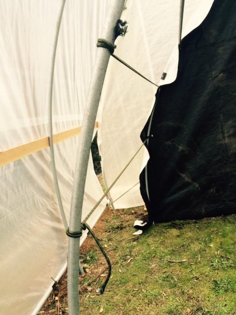
37 37

38 This webbing is important to support the plastic and preventing light leaks. Take the time to install it properly. It should take less than 30 minutes to install if you have 2 people. After you have installed it you can easily adjust its position up or down as needed. After installing the webbing you will want to layout your rollup pipes on either side of the dep frame. The motors will be on the opposite end of the greenhouse from the doors. This means you will want to have your swagged ends of the pipes closer to the door and the normal end farther from the door. IMPORTANT!! MAKE SURE THAT THE FIRST PIPE CONNECTING TO THE MOTOR HAS THE CONNECTOR ATTACHED TO IT THAT WE HAVE PROVIDED FOR YOU. 38

39 First connect all the pipes with self drilling screws. Make sure to use three screws per joint and stagger them. Afterwards you should duct tape the screws so they do not back out. t Or you can use the 1/4 self drilling screws. If you use the self drilling screws you should use 3 of them per joint. MAKE SURE THAT THE PIPE HAS APPROXIMATELY 1 FOOT OVERHANG ON BOTH ENDS 39

40 Now on to the dep tarp!! Installing Your Dep Tarp First you will want to unfold the dep tarp inside the dep area. Run it the length of the dep structure. Leaving an extra foot on either side for overhang. Now gently open the plastic and stretch it evenly over the frame. Make sure that the plastic is straight and square on the dep frame. It is very important that the excess plastic on the ends are equal in length and that the excess on the sides are equal in length. 40
.")
41 After you have squared up the plastic you need to wiggle wire it into place. (if you want you can just wiggle the ends at first and then roll up your plastic with the motors and THEN install the rest of the wiggle wire). Once the plastic is in place it is time to place the rollup pipe on top of the dep tarp. Just walk the length of the dep frame starting at one end and lift the pipe onto the dep tarp. Do this on both sides. Time to install the motors! Installing the Light Dep Motors Place the pivot point at the end of the light dep structure between the dep frame and the greenhouse. Make sure that it is place in the dead center between the ribs of the dep structure. Open the stubs so that they are on opposite sides of each other. Make sure that the pivot point is reasonably level and that the arms move freely back and forth without hitting anything. Keep adjusting until it does. Now it is time to attach a full length pipe to each of the stubs. Use at least 3 self drilling screws. Once you have attached the pipes and place the pivot point in the center you will want to cut the pivot arms to length. To do this you will lay them open and mark where they meet the end of the dep structure. BEFORE YOU CUT YOU WILL NEED TO ACCOUNT FOR THE LENGTH OF THE MOTOR AND THE FITTING. 41

42 You may have to make a few cuts to get it fit just right. Now mount a motor on the end of the arm with the hardware provided. It should look like the picture below from the backside. 42

43 Once the motor is mounted on the arm it is time to connect the rollup pipe. You will have to either push or pull the rollup pipe into position. With the motor and rollup pipes mounted it is time to install the plastic clips on the plastic and rollup pipe. Grab the edge of the dep tarp and gently lift until the rollup pipe is in the air. This is done to remove excess plastic and to move the rollup pipe as close as possible to the dep frame. After this you will want to use the plastic clips to secure the dep plastic to the rollup pipe. Install one approximately 1 every 5 feet. Do this on both sides. Installing The Control Box Now you will choose where to mount the control box. You can mount it inside the light dep structure or outside the greenhouse. You want to choose a location that will provide you ease of access in case you want to make some adjustments to the schedule or troubleshoot. 43


.")
44 Once you have mounted the control box it is time to hook up the motors. To connect the motors you will need to put both motor cables through the cable glands (I can t believe they are called that either). Below is a what the controller looks like on the inside. 44


45 STARTING ON THE LEFT SIDE!! To install the wires you will insert a small flat head screwdriver into the slot and push it down. This will release the latching mechanism and you can then insert one wire into the corresponding hole. Insert and depress screwdriver here. Insert single motor wire here Repeat this process in the next location to the right with the other wire from the same cable. THERE ARE 2 CONNECTOR SITES. MAKE SURE THAT YOU ARE USING THE SAME WIRES FROM THE SAME MOTORS FOR EACH CONNECTOR SITE. MOTOR 1 MOTOR 2 45
46 Repeat until both motors are connected. Make sure that they are securely fastened by tugging on the wires!! Connecting Power to the Control Box Now you are ready to connect power to the control box! Plug it in and start the next step! On Grid Instructions BEFORE YOU PLUG IN THE POWER MAKE SURE TO SET YOUR TIMER TO THE OFF POSITION! 46
47 Move to OFF Position First!!! Off Grid Instructions If you are using off grid power you will need to provide 24V DC electricity to the control box. I recommend using two 12V DC car batteries that are wired in series to produce the 24V DC necessary. If you are unfamiliar with wiring and electricity you should hire an electrician to do this for you. WARNING: PLEASE HAVE AN EXPERT DO THE WIRING FOR YOU TO AVOID POTENTIAL PROBLEMS. Once you have done this you are ready to plug in the power! WARNING: PLEASE HAVE AN EXPERT DO THE WIRING FOR YOU TO AVOID POTENTIAL PROBLEMS. 47

48 BEFORE YOU PLUG IN THE POWER MAKE SURE TO SET YOUR TIMER TO THE OFF POSITION! Move to OFF Position First!!! How To Make The Motors Go Up & Down We designed this system with you in mind. That is why we chose the old school mechanical timers. Everyone knows how to use one of these! Set the time (notice the handy clock in the center!) and pull a pin out and the power goes on at that time. Easy peasy. 48
49 With this control box every time the power is run through it the motors will go one direction. If the controllers sense that no power is flowing through the controller it will reverse direction and go the other way. LET ME REPEAT THAT: WHEN YOU INITIALLY TURN ON THE POWER THE CONTROLLER WILL START TRYING TO GO THE SAME DIRECTION EVERY TIME. What this means to you is simple. If you have it set to the up position on the start up, the controller will try to roll up your dep. If your tarps are down or the closed position no biggie, they just roll up. If your tarps are already rolled up what the controller does is try to initially roll them up again and when it senses that it can t it will reverse the direction. If the controller were having a conversation to itself when it is time to roll up the plastic it would sound something like this when it experiences power running through it. Lets roll up! Lets roll up! Okay we re rolling up! On the other hand if the controller needs to roll down and was having a conversation it would sound something like this when it experiences power running through it. Lets roll up! Lets roll up! Hey we can t roll up anymore! Then lets roll down! Okay we re rolling down! If however you stopped your dep manually while it was rolling down you would first have to let it roll all the way up before you could let it roll down. Super easy 49
50 Setting The Motors! Finally it is time to set the motors and run them! To do this we must first set the timers on the motors to 0. Yes the red and the green. Timers Set To Zero Although these dials look like timers they are not. They actually are limit switches that keep track of the distance they travel. But for our purposes we will call them timers. WARNING: MAKE SURE WHEN SETTING THE TIMER TO NOT GO PAST THE ZERO POSITION. THIS ACTUALLY LOADS THE TIMER TO FULL CAPACITY. 50


51 PAST ZERO POSITION The way these limit switches work is simple. For example if you set the green switch to 20 and the red switch to 0, then turn on the power you will notice that the green switch is counting down from 20 to 0. You will also notice that the red switch is counting up from 0 to 20. What this means is the pipe will roll up a certain distance and unroll that exact same distance when it is time to cover the dep! So once you find the right setting you shouldn t have to adjust it. Now it is time to turn the power on to the motors. To do this go to the control box and turn the switch to the on position on your blue timer. 51
52 Once you move the switch to the on position, the motors may start moving even though you have set them to zero. If you have set them properly they will stop quickly. If they don t stop in less than 30 seconds you should turn off the power at the blue timer and set the motor timers to zero. Now that the motors have stopped it is time to set the motors. To get the motors to roll up properly you need to turn the dial that is on top. Left Side From Back View Right Side From Back View Go to the right side motor and turn the red dial from 20 to 25 and keep the green dial at zero. RIGHT SIDE IN THIS CASE IS ON THE OUTSIDE OF THE DEP LOOKING IN BY THE PIVOT POINT 52
53 Top Dial Bottom Dial 53


54 Red Timer Set From 20 to 25 This should get the motor rolling up the plastic in the proper direction. I call the proper direction rolling up and the improper direction rolling in. Make sure the pipe is rolling up the plastic in the correct direction (like pictured above), otherwise it can rip your dep tarp. 54
55 Make sure the pipes are not rolling back into the frame on the way up because this will rip your dep tarp (pictured above). If the for some reason the red timer on the right side makes the pipes rollup backwards then you will want to turn the red timer back to zero and set the green timer from 20 to 25. Once your plastic is rolling up in the right direction on the right side it is time for you to set the left side. On the left side you should set the red timer to zero and the green timer from 20 to 25. Let the motors roll all the way up the first time. The only reason to stop them is if the pipe roll ups are going to run into the top center support. WARNING: STOP MOTORS IF THE ROLL UPS ARE GOING TO HIT THE TOP CENTER SUPPORT, BECAUSE THIS WILL RIP THE PLASTIC. WARNING: WATCH MOTORS TO MAKE SURE THAT THEY CLEAR THE GREENHOUSE FRAME. If the motors do not clear the greenhouse frame you will have to do some adjusting of the pivot point and length of the rollup pipes. 55
56 Adjusting Your Roll Ups and Plastic Now that you have run you motors you will notice that some sections of the plastic have rolled up faster than others and that some sections appear to have lagged behind. Now it is time to make some adjustments. To adjust the sections that have lagged you will first need to mark the location of the section that has lagged. Next you will need to reverse the motor until it reaches the ground or the starting point. Once it has completely unrolled you will need to go to the section that was lagging and remove the clips. Next you will need to lift the plastic until the pipe is off the ground. You will want to remove any slack that is in the plastic. Once you have done that replace the clips and run the motors to the top again. Repeat this process until you have removed all of the slack in the plastic in the lagging sections. If you find that one section is still lagging don t worry there is an easy fix! All we need to do to make this section catch up to the faster section is to make the diameter of the roll in this section larger. To do this you need to unroll the plastic all the way and then securely tuck between the pipe and the plastic a long piece of bamboo. This will increase the diameter of the roll quickly and easily. Remember all we are concerned with is getting it to roll up evenly. This method works. Of course you can use something else besides bamboo. I have found bamboo to work rather well. Now roll it up again and test it. You may need to add more bamboo or you may even need to add a smaller piece of bamboo. WARNING: MAKE SURE TO WATCH IT ROLL UP A FEW TIMES SO THAT YOU HAVE IT ROLL UP TOO FAR AND RIP THE PLASTIC!! 56

57 Setting The Timer Last step to the set up! Now all you need to do is set the open and close times. First you will need to set the timer to the correct time of day. Spin the dial until the clock in the center of the timer matches the time of day. Clock in the center of the timer Set switch to Auto Next you need to set the time you want it to close. To do this you will pull out two tabs on the timer. This will supply power to the motor for 30 minutes. This is longer than the motors need but that is okay because of the limit switches on the motors. To open the light dep just set the time you want it to open by pulling out 2 tabs. And set the switch to Auto. That is it. You will of course want to be there the first few times that the auto light dep is being run just to make sure that it running correctly. 57
58 Manually Opening and Closing The Light Dep To manually open or close the light dep just turn the switch from Auto to On. This will make the motors either open the dep or close the dep depending on whether the dep is open or closed. If the dep is open when you switch the timer from Auto to On it will start to close the dep and if the dep is closed when you switch the timer from Auto to On it will open it up. Every time the timer is switched on either manually or with the timer it will automatically reverse the direction of the motors from the last time the motors were run. Maintaining Your System The system should be relatively problem free. However you should check the system at least weekly to make sure that it is running properly. If you are doing your job of paying attention to your plants and your dep system you will be able to head off any potential problems long before there are any catastrophes! 58
Side "A" Stake here. Side "C" Side "D" Side "B" Here Shirley and I are setting up a 10 X 16 ground work.
 Choosing the Location It is always best to locate your greenhouse so that it can receive maximum sunlight at all times of the year especially in winter months. If Possible orient the long side towards
Side "C" Stake here. Side "B" Here Shirley and I are setting up a 10 X 16 ground work.
 Choosing the Location It is always best to locate your greenhouse so that it can receive maximum sunlight at all times of the year especially in winter months. If Possible orient the long side towards
Low/High Tunnel Greenhouse Plans
 Low/High Tunnel Greenhouse Plans Tools Needed (See the complete list of Greenhouse Tools) Hacksaw or Reciprocating Saw Socket Wrench, Adjustable Wrench or Nut Drivers Electric Drill with Drill Bits Sledge
Hoop House Plans By Steve Robinson
 Hoop House Plans By Steve Robinson This Ebook is Shareware It is meant to be shared by farmers alike. I give you permission to share this EBook to as many people as you like. It can not be sold, but it
NON-ELECTRIC DOG FENCES
 NON-ELECTRIC DOG FENCES Thank you! Thank you for ordering your non-electric dog fence kit from Pet Playgrounds. In less than a day you will have your very own personal dog park installed on your property.
1. Layout. Step 1. Step 2. Step 3. Fig. 1
 1-3/8 Panel Clamp Tools You Will Need: Tape Measure, Mason s String, Stakes, Hole Digger, Shovel, Level, Wheelbarrow, Wrenches or Adjustable Wrench, Hacksaw, Pliers, Cutting Pliers, Fence Stretcher and
Ledgewood Farm greenhouse. construction
 Ledgewood Farm greenhouse How do I Start? construction to I m Finished! Post layout The string will be 7 above the ground and the posts will be driven until the proper drill hole is at the string. Spacing
Congratulations! Your dog is going to love you!
 DIY INSTRUCTIONS Congratulations! Your dog is going to love you! Thank you for ordering your non-electric dog fence kit from Pet Playgrounds. In less than a day you will have your very own personal dog
Assembly Instructions
 18' W x 10' H or 12' H Peak Style Frame Assembly Assembly Instructions Before you start: 2+ individuals recommended for assembly, approximate time 3 hours. Recommended tools: Power Drill, Safety Glasses,
The Festival Assembly Instructions
 The Festival Assembly Instructions Toll Free: 866.768.8465 Hours: 9-5 Monday-Friday EST www.homeplacestructures.com Package ships as shown CONTACT INFORMATION: HomePlace Structures 301 Commerce Drive New
GrowSpan Series 500 Roll-Up Ends
 GrowSpan Series 500 Roll-Up Ends Photo may show a different but similar model. Doorframe materials are not included. 2016 Growers Supply All Rights Reserved. Reproduction is prohibited without permission.
ClearSpan Mini Grab Bag Shelters
 ClearSpan Mini Grab Bag Shelters Photo may show a different but similar model. Baseboard is not included. 2008 ClearSpan All Rights Reserved. Reproduction is prohibited without permission. STK# DIMENSIONS
Mount to the Wall INSTALLATION MANUAL
 Mount to the Wall 15 Locate the Wooden Studs This step applies to wooden stud wall installation only. Determine and mark the exact locations of two stud centers on the wall. Wooden studs should be spaced
Hardware and Components:
 Hardware and Components: (A) 5/16 x 2 Hex Bolt (B) 5/16 x 2-1/4 Hex Bolt (C) 5/16 x 2-1/2 Hex Bolt (D) 4X 5/16 x 3/4 Hex Bolt (E) 4X 5/16 x 1-1/4 Hex Bolt (F) 11X 5/16 Flat Washer (G) 12X 5/16 Nylock Nut
Clearview Railing System Installation Instructions
 Clearview Railing System Installation Instructions Disclaimer: AGS Stainless, Inc. has its Clearview Railing Systems designed by a professional engineer to meet the requirements of the latest national
ClearSpan Mini Grab Bag Shelters
 ClearSpan Mini Grab Bag Shelters Photo may show a different but similar model. Baseboard is not included. 2008 ClearSpan All Rights Reserved. Reproduction is prohibited without permission. STK# DIMENSIONS
E-Z GROW HOBBY GREENHOUSE. I n s t r u c t i o n M a n u a l & D i s c l a i m e r s
 E-Z GROW HOBBY GREENHOUSE I n s t r u c t i o n M a n u a l & D i s c l a i m e r s Contractors/Installers Note: This manual is the property of the customer. Please leave it in the possession of the customer.
Hoop House Construction Plans
 Kerr Center for Sustainable Agriculture (918) 647-9123 24456 Kerr Rd. Poteau, OK 74953-5215 Copyright 2017 Published Fall 2017 www.kerrcenter.com Hoop House Construction Plans This document explains how
15 Ft. x 39 Ft. Hoop House Construction
 15 Ft. x 39 Ft. Hoop House Construction Hoop House 15 Ft. x 39 Ft. HOOP HOUSE The Hoop House, Cold Frame and High Tunnel can be basically the same structure with minor changes to the design. The Hoop House
Baby Grande or Grande Crank Shade with Cables and Housing Installation Instructions
 Baby Grande or Grande Crank Shade with Cables and Housing Installation Instructions Tools Needed Drill 3/8 Metal Drill Bit Screwdriver (Flat & Phillips) Measuring Tape Pencil 4 Level Plumb Line ¼ Masonry
6a. Eight Steps to Chain-Link Fence Installation
 6a. Eight Steps to Chain-Link Fence Installation Before You Start You will need the following tools to install your chain-link fence: Post hole digger Wheelbarrow, shovel and hoe for mixing concrete Tape
Deck Mount Installation with Bench
 Deck Mount Installation with Bench 1. Mark track with square. 2. Cut tracks with saw. 3. Drill ¼ hole (if needed.) 4. Countersink track. 5. Countersink all track 6. File all track ends. ends. 7. Lay out
ClearSpan Mini Cold Frames
 ClearSpan Mini Cold Frames Photo may show a different but similar model. 2009 ClearSpan All Rights Reserved. Reproduction is prohibited without permission. STK# DIMENSIONS 105152 6' W x 5' H x 6' L 105153
Plug-n-Show Stake Down Pixel Tree Kit 16 strips of 25 pixels Assembly Instructions
 www.lightorama.com Plug-n-Show Stake Down Pixel Tree Kit 16 strips of 25 pixels Assembly Instructions Read all instructions before you start Kit assembly! STEP 1. Check that all parts are included Parts
AWNING / PATIO COVER INSTALLATION INSTRUCTIONS
 AWNING / PATIO COVER INSTALLATION INSTRUCTIONS Before You Begin Read the installation instructions thoroughly before beginning the installation procedure. Perspective In the Awning Instructions, Back means
AUDI A8 D3 REPLACING THE OUTSIDE DRIVER DOOR HANDLE
 AUDI A8 D3 REPLACING THE OUTSIDE DRIVER DOOR HANDLE The keyless entry system in the D3 is a great feature. If you have the car key fob in your pocket, putting your hand under the door handle will unlock
ClearSpan End Frame Kit 30' Wide x 11' High
 ClearSpan End Frame Kit 30' Wide x 11' High Diagram shows the end frame kit for an end wall without a door. (Door and end panel are purchased separately.) Rafter and mounting feet shown in the above diagram
BUMP GATE FITTING INSTRUCTIONS.
 1 BUMP GATE FITTING INSTRUCTIONS. HEAVY DUTY MODEL FOR STEEL POSTS. Hinge post Lock post Bump arms Two-way lock Thank you for purchasing a Bump Gate. This device will provide you with many years of good
50 W ide. Future Trac G able E nd. Installation Instructions AIGE
 G able E nd W ide TopTec Products, LLC 7601 Highway 221 Moore, SC 29369 Phone: (800) 845-2830 Fax: (800) 921-77 e-mail: sales@toptecproducts.com www.toptecproducts.com AIGE 2003915 General Information
Hardware and Components:
 Hardware and Components: (A) 4X 5/16 x 1 Carriage Bolt (B) 2X 5/16 x 2-1/4 Carriage Bolt (C) 2X 5/16 x 3-1/4 Hex Bolt (D) 2X 5/16 x 3/4 Hex Bolt (E) 2X 5/16 x 1-1/4 Hex Bolt (F) 5/16 x 2-1/4 Hex Bolt (G)
INSTRUCTION BOOKLET #34. For Wallbed models: KING SIZE SIERRA WITH STORAGE HEADBOARD
 For Wallbed models: KING SIZE SIERRA WITH STORAGE HEADBOARD INSTRUCTION BOOKLET #34 WARNING! ALL MURPHY/WALLBED SYSTEMS CONTAIN STORED ENERGY. FAILURE TO USE AND FOLLOW THESE INSTRUCTIONS DURING THE INSTALLATION
ClearSpan Economy Round Style High Tunnel
 ClearSpan Economy Round Style High Tunnel Photo may show a different but similar model. 2012 ClearSpan All Rights Reserved. Reproduction is prohibited without permission. Revision date: 0112 STK# PB01725R6
Baby Grande or Grande Crank Shade with Cables and Housing Installation Instructions
 Baby Grande or Grande Crank Shade with Cables and Housing Installation Instructions Tools Needed Drill 3/8 Metal Drill Bit Screwdriver (Flat & Phillips) Measuring Tape Pencil 4 Level Plumb Line ¼ Masonry
ClearSpan Majestic Greenhouse Film Roof with Roll-up Sides
 ClearSpan Majestic Greenhouse Film Roof with Roll-up Sides 28' Wide Photo may show a different but similar model. 2009 ClearSpan All Rights Reserved. Reproduction is prohibited without permission. STK#
Manual for Shelter W3,5xL8,0xH3,8m
 Manual for Shelter W3,5xL8,0xH3,8m 22-11-2016 Congratulations on your purchase of our instant shelter. This unit is a combination of excellent manufacturing and design. It is comprised of a rigid frame
ClearSpan End Frame Kit 26' Wide x 12' High
 ClearSpan End Frame Kit 26' Wide x 12' High Diagram shows the end frame kit for an end wall without a door. (Door and end panel are purchased separately.) Rafter and struts shown in the above diagram are
PROTECT-A-POOL INGROUND REMOVABLE SAFETY FENCE
 PROTECT-A-POOL INGROUND REMOVABLE SAFETY FENCE I N S T A L L A T I O N I N S T R U C T I O N S INSTALLATION TOOLS The following tools are required for installation. Chalk Pencil Utility Knife Tape Measure
CertainTeed INSTALLATION GUIDE SIMTEK FENCE PRODUCTS. Fence Installation Guide 3', 4' & 6' High
 CertainTeed INSTALLATION GUIDE SIMTEK FENCE PRODUCTS Fence Installation Guide 3', 4' & 6' High INSTALLATION GUIDE These instructions are designed to assist both professional installers and do-it-yourselfers
ClearSpan Majestic Greenhouse Film Roof with Roll-up Sides
 ClearSpan Majestic Greenhouse Film Roof with Roll-up Sides 56' Wide Photo may show a different but similar model. 2009 ClearSpan All Rights Reserved. Reproduction is prohibited without permission. STK#
48 in. X 96 in. 500 Pound Capacity Motorized Overhead Storage Unit Installation Guide [OPTION B] MODEL # PRM4X8 Patent Pending
![48 in. X 96 in. 500 Pound Capacity Motorized Overhead Storage Unit Installation Guide [OPTION B] MODEL # PRM4X8 Patent Pending](/thumbs/81/83353561.jpg "48 in. X 96 in. 500 Pound Capacity Motorized Overhead Storage Unit Installation Guide [OPTION B] MODEL # PRM4X8 Patent Pending") 48 in. X 96 in. 500 Pound Capacity Motorized Overhead Storage Unit Installation Guide [OPTION B] MODEL # PRM4X8 Patent Pending 1 Table of Contents Table of Contents PAGES Installation Support 3 Safety
48 in. X 96 in. 500 Pound Capacity Motorized Overhead Storage Unit Installation Guide [OPTION B] MODEL # PRM4X8 Patent Pending 1 Table of Contents Table of Contents PAGES Installation Support 3 Safety
Assembly Instructions 10 X 10 Aluminum Roof Support
 Assembly Instructions 10 X 10 Aluminum Roof Support Aluminum Roof Support Bolt Package 16-5/16 X 2 ¼ SS Bolt 24-5/16 X 1 SS Bolt 40-5/16 SS Nylon Lock Nuts 16-5/16 SS Flat Washers 28-4 ½ Wood Screws 36-1
Assembly Instructions 10 X 10 Aluminum Frame Building
 Assembly Instructions 10 X 10 Aluminum Frame Building 27 97 9 8 47 36 74 52 10 10 X 10 Square Building W/ Dome Includes: The Steel Entry Door with a Dead Bolt Lock assembly and Aluminum Door Frame. Metal
12'W x 10'H RoundTop Frame Assembly Please read and understand instructions completely before assembly.
 12'W x 10'H RoundTop Frame Assembly Please read and understand instructions completely before assembly. Layout out frame parts as shown and match up items with quantity to make sure no parts are missing.
Playground Assembly Instructions
 Before You Begin Playground Assembly Instructions Locate the playground set on firm, level ground. Assemble the playground on or close to its permanent location Two people are recommended to assemble the
Moo-Tel Calf Hutch CLEARSPAN ANIMAL HOUSING W x 12 L W x 18 L W x 24 L
 Moo-Tel Calf Hutch Photo may show a different but similar model. 2008 ClearSpan All Rights Reserved. Reproduction is prohibited without permission. STK# DIMENSIONS 102852 14 W x 12 L 102853 14 W x 18 L
Post & Rail Crossbuck
 Post & Rail Crossbuck 1. Getting Started 6. Crossbuck Be sure to call underground prior to digging Assemble gates (if necessary) and decide where they will be located Stake out the fence line Space and
GrowSpan Round Cold Frames
 GrowSpan Round Cold Frames Photo may show a different but similar model. 2016 Growers Supply All Rights Reserved. Reproduction is prohibited without permission. STK# DIMENSIONS 103099 12' W x 8' H x 24'
Series 1500 Aluminum Door Canopy
 Series 500 Aluminum Door Canopy with Sidewings It is our recommendation that you read instructions carefully prior to assembly and installation. Series 500 with Sidewings mounting bar (A) top trim (B)
Open shipping crate and separate all of the different parts. Over The Top Shelters LLC
 ASSEMBLY INSTRUCTIONS FOR MODEL SH122110GN and SH122110GY Open shipping crate and separate all of the different parts. Count each part and match up with parts list. Shortages or damaged parts should be
Spring Loaded All Season Roll-Up Doors
 Spring Loaded All Season Roll-Up Doors STAND-OFF MOUNTING METHOD INSTALLATION INSTRUCTIONS READ THIS FIRST Carefully examine the crate(s) for damage before opening. If the carton is damaged, immediately
Skybolt V2 Construction Manual
 Skybolt V2 Construction Manual Property of www.ppgplans.com Do not duplicate or make public. Warnings & Disclaimers. This product shows how to build a basic frame only for Powered Paragliding. It is the
MODULAR HIGH TUNNEL INSTALLATION GUIDE
 9615 Grandview Rd. Kansas City, MO 64137 Version: 15 JAN -2015 Sustainable Agriculture Solutions MODULAR HIGH TUNNEL INSTALLATION GUIDE (816) 444-7330 SmallFarmTools.com Thank you for purchasing a Modular
SwingSafe Swing-Away Mailbox Support Diagram
 SwingSafe Swing-Away Mailbox Support Diagram Wood Mounting Plates Top Arm (B) Muffler Clamps (A) Carriage Bolts and Nuts Bottom Arm 4-Foot U-Channel Post USPS Recommended 42-44 Height Ground Slope Hex
The Useless Machine. Parts Only - Build Guide v0001
 TM The Useless Machine Parts Only - Build Guide v0001 For the best outcome, follow each step in order. We recommend reading this guide entirely before you get started. Tools required: One phillips screwdriver,
Greenhouse Construction Manual
 Greenhouse Construction Manual 30' Greenhouse Unit Manufactured By: CVS SUPPLY 2455 County Road 200 Dundee OH 44624 (Leave Message at 877-790-8269) SUMMARY OF CONTENTS GETTING STARTED Thank You! Materials
22'W x 13'H Peak Style Shelter Frame Assembly Instructions
 22'W x 13'H Peak Style Shelter Frame Assembly Instructions Recommended Tools Please read instructions COMPLETELY before assembly. This shelter MUST be securely anchored. THIS IS A TEMPORARY STRUCTURE AND
WeatherShield Covered Walkway and Connect-A-Building
 WeatherShield Covered Walkway and Connect-A-Building Photo may show a different but similar model. 2014 ClearSpan All Rights Reserved. Reproduction is prohibited without permission. STK# DIMENSIONS 104303
ClearSpan Super Moo-Tel Building 26' Wide
 ClearSpan Super Moo-Tel Building 26' Wide Photo may show a different but similar model. 2012 ClearSpan All Rights Reserved. Reproduction is prohibited without permission. STK# PB01500R3/R4 PB01510R3/R4
Assembly Instructions
 Unite Panel System Hinge Door July 2016 #12 x / slotted hex washer head bolt Figure 1 threshold bracket frame Detail F threshold bracket threshold bracket (installed) #12 x / slotted hex washer head bolt
SuperTrack Parts List
 SuperTrack Parts List [indicates number for 6 lane tracks] SuperTrack Installation Instructions www.supertimer.com 1-800-654-2088 1 Track Instruction Manual (this booklet) 2 Start sections [3] Start Gate
Installation And Care Instructions. Vertical Honeycomb Shades
 Installation And Care Instructions Vertical Honeycomb Shades Rev 5/2013 Table Of Contents Getting Started... 3 Parts Overview... 4 Materials Required... 5 Tools Required... 6 Outside Mount Installation...
ClearSpan PolyMax Windbreak Wall
 ClearSpan PolyMax Windbreak Wall Photo may show a different but similar model. 2007 ClearSpan All Rights Reserved. Reproduction is prohibited without permission. Revision date: February 2007ldg STK# DIMENSIONS
VYTEX PREMIUM SLIDING GLASS DOOR. Table of Contents. Precautions and Safety 2. Tools Required...3. Inspect and Prepare Door...4
 VYTEX PREMIUM SLIDING GLASS DOOR Table of Contents Precautions and Safety 2 Tools Required...3 Inspect and Prepare Door...4 Hardware and Parts Check List....4 Master Frame Assembly 5 Master Frame Installation..7
Tools Needed Hardware Provided (per shade) Hardware Needed
 Hardware Needed") Baby Grande or Grande Motorized (XQ5 Premium) Shade with Cables and Housing Installation Instructions Tools Needed Hardware Provided (per shade) Hardware Needed Drill 3/8 Metal Drill Bit Measuring Tape
Baby Grande or Grande Motorized (XQ5 Premium) Shade with Cables and Housing Installation Instructions Tools Needed Hardware Provided (per shade) Hardware Needed Drill 3/8 Metal Drill Bit Measuring Tape
Assembly Instructions
 InTandem Table System November 20 InTandem Table System - Worksurface #4 x/" 4 wood screw power beam Tools Provided T-0 Extended Torx Driver T-25 Torx Driver Additional Tools Required Soft protective
Plastic Roof Covering (In Preparation)
") Plastic Roof Covering (In Preparation) Please see how to videos online for further clarification Regardless of which covering will be installed on your building, the success or failure of the job, and
Plastic Roof Covering (In Preparation) Please see how to videos online for further clarification Regardless of which covering will be installed on your building, the success or failure of the job, and
GIRTS ON BACK OF BUILDING
 GIRTS ON BACK OF BUILDING ALL GIRTS ARE 1 1/2 SQUARE TUBE. GIRT LENGTHS FOR 12, 20, 24, AND 30 WIDE BUILDINGS: ON 12 WIDE BUILDINGS GIRTS ARE 67 3/4 LONG ON 20 WIDE BUILDINGS GIRTS ARE 56 3/4 LONG ON 24
Precision Steel Car s 100 T Steel Coil Car
 Precision Steel Car s 100 T Steel Coil Car Precision Steel Car www.precisionsteelcar.com info@precisionsteelcar.com Paul Vernon: (513) 571-5739 Revised 4/30/2009 Contents of Kit Main Tube Side Frame 2
GrowSpan 30' Wide Series 500 Tall Greenhouses
 GrowSpan 30' Wide Series 500 Tall Greenhouses Photo may show a building of a different length and style. Frame shown includes optional roll-up sides and customer-supplied baseboards. Building shown is
INSTALLATION AND CARE INSTRUCTIONS
 INSTALLATION AND CARE INSTRUCTIONS Vertical Applications Honeycomb Shades 52 C8-10-3401 Rev 2/14 CONTENTS Introduction...2 Before You Begin...3 Vertical Application Parts Overview...4 Materials Required...5
EASY-IN POOL STEP SYSTEM NE132
 EASY-IN POOL STEP SYSTEM NE132 This instruction manual features multiple guides for the step unit components. 7939 EASY POOL STEP (NE113) FOR USE WITH: EASY-IN POOL STEP (NE126) 6492 PARTS & HARDWARE FOR
ClearSpan Majestic Greenhouse Film Roof with Polycarbonate Sides
 ClearSpan Majestic Greenhouse Film Roof with Polycarbonate Sides 84' Wide Photo may show a different but similar model. 2016 ClearSpan All Rights Reserved. Reproduction is prohibited without permission.
400A 40113V, 401A 40120V, & 401AL 40120VL ALUMINUM VERTICAL 4000 LB LIFT INCLUDES SCREW LEG ASSEMBLY INSTRUCTIONS
 12/11/07 PAGE 1 OF 12 400A 40113V, 401A 40120V, & 401AL 40120VL ALUMINUM VERTICAL 4000 LB LIFT INCLUDES SCREW LEG ASSEMBLY INSTRUCTIONS Thank you for purchasing our product! *Please read these instructions
Installing Cable Wire for Hanging Curtains
 Published on Sew4Home Installing Cable Wire for Hanging Curtains Editor: Liz Johnson Tuesday, 01 December 2009 9:00 I had to bring in the big guns for this project as my own 'power tool' experience leans
Sliding Door Kit
 YOU MUST READ THIS DOCUMENT BEFORE YOU BEGIN TO ASSEMBLE THE DOOR KIT. Thank you for purchasing this GrowSpan door kit. When properly assembled and maintained, this product will provide years of reliable
Insolroll Clutch Operated Shades Installation Instructions Installation Instructions
 All clutch operated shades are shipped fully assembled and ready for installation. Mounting screws are not provided. Screws for chain guide installation to meet the child safety standards are provided.
WeatherShield Daddy Long Legs Canopy
 WeatherShield Daddy Long Legs Canopy Photo may show a different but similar model. 2010 ClearSpan All Rights Reserved. Reproduction is prohibited without permission. Revision date: 06.210 STK# 1220RV10W10
Installation Guidelines
 Page 1 Tools You ll Need 4 ft. Carpenter s level Chalk line (to mark U channel locations) Cordless drill/nut driver Caulking gun Chop saw with a metal cutting blade on it (required to make accurate and
MOTORIZED STANDARD SHADE WITH CABLES Installation Instructions
 Tools Needed Drill Measuring Tape Pencil 2 Level Plumb Line ¼ Masonry Drill Bit Hammer Linesmans Pliers Cable Cutters Phillips & Flat-Head Screw Driver 11/32 Socket or Open End Wrench 5/32 Allen Wrench
Dura-Lock Roof System
 DLR-14 Dura-Lock Roof System Assembly and Installation Instructions Read the instructions before starting the job. They explain the steps required to produce a finished product that will meet factory specifications.
 INSTRUCTION BOOKLET #C0 Watch step by step installation instructions at: https://www.wallbedsbywilding.com/wallbed-installation-studio-series/ WARNING! ALL MURPHY/WALLBED SYSTEMS CONTAIN STORED ENERGY.
ClearSpan Twist-of-the-Wrist Assembly Instructions
 ClearSpan Twist-of-the-Wrist Assembly Instructions Curved-Wall for Roll-Up Side Flat-Wall for Curtain Application 2008 ClearSpan All Rights Reserved. Reproduction is prohibited without permission. Revision
N. 15th Street, Middlesboro, KY FLIP TARP DUMP BODY INSTALLATION INSTRUCTIONS
 1-800-248-7717 1002 N. 15th Street, Middlesboro, KY 40965 FLIP TARP DUMP BODY INSTALLATION INSTRUCTIONS Congratulations on your purchase of a Mountain Flip Tarp Dump Body tarping system. With tarping systems
Vertical Honeycomb Shades
 Step by Step Installation Instructions Vertical Honeycomb Shades Customer Service 800.248.8888 or visit us online at smithandnoble.com Thank you for purchasing from Smith+Noble. Your new shades have been
WARNING: Prior to installation, turn the power off to the vending machine and unplug it from its power source. Also, make sure to level the machine.
 Installation of Gum and Mint Tray for National 147, 157, 167 Important Note: Please read all instructions thoroughly before continuing with installation of kit. If you are having problems installing the
IMPORTANT!!! ASSEMBLY ASSEMBLY INSTRUCTIONS. (Internal Dimensions)
") ASSEMBLY ASSEMBLY INSTRUCTIONS (Internal Dimensions) Ent Spec Edition Ltr v-0- Overall dimensions including base: 7. L x 9 W x 0 H cms 97.5" L x 7" W x 8.7" H IMPORTANT!!! Please read these instructions
ASSEMBLY ASSEMBLY INSTRUCTIONS (Internal Dimensions) Ent Spec Edition Ltr v-0- Overall dimensions including base: 7. L x 9 W x 0 H cms 97.5" L x 7" W x 8.7" H IMPORTANT!!! Please read these instructions
ClearSpan 38' Wide Aircraft Hangar
 ClearSpan 38' Wide Aircraft Hangar Photo may show a model of a different length. 2008 ClearSpan All Rights Reserved. Reproduction is prohibited without permission. STK# DIMENSIONS 107556 38' W x 15' H
ROUND TOP RV SHELTER
 ROUND TOP RV SHELTER 94182 ASSEMBLY AND OPERATING INSTRUCTIONS Visit our website at: http://www.harborfreight.com Read this material before using this product. Failure to do so can result in serious injury.
ClearSpan Front Roll-Up Kit Installation Guide
 ClearSpan Front Roll-Up Kit Installation Guide Roll-up panel opened. Roll-up panel closed. Actual building and panel may differ from what is shown. 2008 ClearSpan All Rights Reserved. Reproduction is prohibited
PAT installation of a Sun Dome over a in-ground
 PAT. 3766573 Installation of Sun Domes for in-ground pool GENERAL INSTRUCTIONS: STEP 1. Read thru the entire instructional materials before beginning any installation. You will find that the installation
INSTALLATION AND CARE INSTRUCTIONS
 INSTALLATION AND CARE INSTRUCTIONS Vertical Applications Honeycomb Shades CONTENTS Introduction...2 Before You Begin...3 Vertical Application Parts Overview...4 Materials Required...5 Tools Required...6
ClearSpan Attached-Style Awning
 ClearSpan Attached-Style Awning Photo may show a different but similar model. 2007 ClearSpan All Rights Reserved. Reproduction is prohibited without permission. Revision date: July 2007ldg STK# DIMENSIONS
FOR PROFESSIONAL GARAGE DOOR INSTALLERS
 Composite Garage Doors Installation Instructions FOR PROFESSIONAL GARAGE DOOR INSTALLERS Tools required Screwdriver Claw Hammer Locking Pliers Power Drill Level with a 3/32" Drill Bit Utility Knife 9/16",
Purlin Installation. Step 1: Start at one end and work your way down the tunnel. Step 2: Lay out a measuring tape between the ground posts
 Purlin Installation Materials: Purlin pieces, cross-connector clamps, drill, ¼ selftapping screws, hack saw, measuring tape, plumb bob, marker, duct tape Step 1: Start at one end and work your way down
Ranch Rail Vinyl Fence
 Ranch Rail Vinyl Fence INSTALLATION INSTRUCTIONS These instructions are to be used as general guidelines for the installation of your vinyl fence under normal installation conditions. Local conditions
Nancy s Knit Knacks LLC 4 Yard Option Upgrade Kit Assembly Instructions and User Manual
 Nancy s Knit Knacks LLC 4 Yard Option Upgrade Kit Assembly Instructions and User Manual Thank you for purchasing our 4 Yard Option (4YO) Upgrade Kit. To install this upgrade you are simply going to assemble
INSTRUCTION BOOKLET #C20
 INSTRUCTION BOOKLET #C0 WARNING! ALL MURPHY/WALLBED SYSTEMS CONTAIN STORED ENERGY. FAILURE TO USE AND FOLLOW THESE INSTRUCTIONS DURING THE INSTALLATION PROCESS COULD RESULT IN SEVERE PERSONAL INJURY TO
7 X 10 X 6 SHELTER 7 X 16 X 6 SHELTER 12 X 10 X 6 SHELTER 12 X 16 X 6 SHELTER
 ASSEMBLY INSTRUCTIONS FOR 7 X 10 X 6 AND 7 X 16 X 6 ATV SPORT SHELTER ACTUAL FRAME SIZES: 7 X 9-1 1/2 X 6 AND 7 X 13-7 1/2 X 6 AND 12 X 10 X 6 AND 12 X 16 X 6 ATV SPORT SHELTER ACTUAL FRAME SIZES: 12 X
Removing and Replacing the Y-truck
 Service Documentation Removing and Replacing the Y-truck To remove and replace the Y-truck you will need the following tools: 4mm Allen wrench 12mm stamped flat wrench #2 Phillips screwdriver (magnetic
INS A KSCR INSTALLATION INSTRUCTIONS STANDARD PROCEDURE. 1. Unpacking the KSCR Splicing the KSCR (If Required)...
...") INS-88.500-0A KSCR INSTALLATION INSTRUCTIONS STANDARD PROCEDURE 1. Unpacking the KSCR... 2 2. Splicing the KSCR (If Required)... 4 3. Assemble Curb and Rail Corners... 5 4. Install Cross Bracing (If Required)...
INS-88.500-0A KSCR INSTALLATION INSTRUCTIONS STANDARD PROCEDURE 1. Unpacking the KSCR... 2 2. Splicing the KSCR (If Required)... 4 3. Assemble Curb and Rail Corners... 5 4. Install Cross Bracing (If Required)...