Gas Lifts Write-Up. This is what you will find:
|
|
|
- Cory Bates
- 6 years ago
- Views:
Transcription

1 Gas Lifts Write-Up When you open your package from Dev the contents will look like this 6 brackets and two ball studs. The ball studs are for use in the frunk and they have a metric thread so they can bolt right in to a threaded hole that Toyota was kind enough to already provide. Cut the nylon cable tie that holds it all together and,,, This is what you will find:
. F=Frunk and D=Driver s Side and P=Passenger Side.")
2 Turn the pieces over and you will find identifying information for each bracket on the back. The next photos are for the 2 brackets you will use in the frunk. There are only two brackets for the frunk (and 4 brackets for the engine compartment). F=Frunk and D=Driver s Side and P=Passenger Side. (Please note that these instructions are for left hand drive cars. If you live where they drive on the proper side of the road, please keep this in mind and reverse the nomenclature). So here is a picture of FD and FP from the top side and...

3 ... here is a picture of FD and FP from the back side. Make sure that you do not accidentally rub off the identifying lettering on the back side of your brackets. If it starts coming off, get a Sharpie pen and put it back on so you don t get lost in the install process.

4 The next set of brackets (BD and BP) are for the engine compartment and these two brackets will get installed on the side of the engine compartment near the tail lights.

5 The last set of brackets will be installed onto the engine bay lid and they are marked ECD and ECP
.")
6 There are a few pieces of hardware that you will need to purchase separately to complete the install of your brackets/gas struts. Four gas struts which you can purchase on-line from McMaster. You ll need two for the frunk and two for the engine compartment hood. (see list below). Please note that McMaster refers to these as Gas Springs with Ball-Joint Fittings which I am sure is the proper name for these parts. However, throughout this write-up they are referred to as Gas Struts. I purchased mine from McMaster in March of 2012 and the price shipped to my door for all four struts was just under $ Here is the web link: Just type the part numbers in the "find box" and you will see the parts. 2 30lb 20" gas struts for the frunk, part # 4138T lb 15" gas struts for the engine hood, part # 4138T553 You will also need to supply the following nuts and bolts:

7 6 Nylon locknuts size 5/ You can use regular nuts and use lock tight to keep them in place. Personally, I like the nylon locknuts so that s why I went with them. You will need these nuts to attach the balls studs that came attached to gas struts you ordered. You only need 6 because your kit included 2 metric ball studs that you will use in the gas strut installation in the frunk. 2 M6 1.0x20mm hex bolts* to attach BD and BP to the rear engine compartment (near tail lights) 2 M6 1.0 Nylon lock nuts* for the bolts listed above. You don t have to use nylon lock nuts. I like them because I trust them to not work themselves out from road vibration. (* You don t actually need to use these metric nuts and bolts you could use SAE, if you want. I personally prefer to keep everything on the car metric whenever possible -- because it s easier for me to apply the right size wrenches/sockets when everything is uniformly metric.) Grease. You will lose some of the grease that was in the ball sockets of the gas struts when you take the ball studs out to install them in the brackets. I just used some wheel bearing grease from past brake jobs and smeared a small amount inside the ball socket with a Q-tip to replace the grease. See photos below.

8 If you want to paint your brackets to match your car s color, it would be a good idea to wash them and use a scotch bright pad to scuff the surface before you prime and paint. I use Tide detergent in a bucket of water because Tide is great at dissolving residual grease and crude left on parts in the manufacturing process and it is great for prepping the surface for paint.

9 From this point forward, you will notice that the once shinny aluminum brackets are now painted 040 Super White to match my car. I also painted the nuts and the bolts for a more factory finished look to the whole project. Before we go any further, here are the tools I used to do this install:
 12mm wrench and socket Blue Lock Tight.")
10 Metal ruler/straight-edge 2 blue painter s tape 1 masking tape Black Sharpie pen White grease pencil Square Knife with a sharp blade Hack saw Phillips screwdriver Two ½ combination wrenches 10mm wrench and socket (and I also used a 10mm deep socket) 12mm wrench and socket Blue Lock Tight. (not pictured is a file used to smooth the plastic after cutting the frunk surround to accommodate the gas struts). Let s get started. Open the frunk

11 And remove the frunk plastic surround. You ll first need to remove the cover for the spare tire and then remove the little push pin trim holders. You ll do this by gently pushing in on the pin in the center of the fastener...

12 ... and then just lift out the entire fastener.

13 If I counted correctly, there will be 18 of these little fasteners that you will need to remove before you can easily remove the frunk plastic surround. I have found that these little fasteners easily break, so you might want to stock-up on a bunch of extra pins. Here is a great source for these pins: You might want to order a bunch of TR127 or TR288 pins just so you have some on hand. They are also used elsewhere throughout the Spyder. Mr. T wants a fortune for these little critters, so you might want to stock-up. I think I broke about 4 of them on this project so I just ordered 100 of the TR127s and 60 of the TR288s for safe keeping. Okay, now back to the gas lifts project. Once you have all the fasteners out, remove the frunk surround plastic. It looks like this leaned up against the wall of my garage.

14 Measure ¾ back from the head light tab notches on the sides of the surround. This is where the white grease pencil, the straight edge and the square come in really handy.

15 Then measure 5/8 along the side all the way to the back of the surround, like this:

16

17 Measure the same for both sides of the frunk surround and then get out your trusty hack saw and cut straight and even. Left side:

18

19 Right side: Next we will prepare the frunk for installing the brackets and ball studs. This is where you will use the 2 blue painters tape, Sharpie pen, 1 masking tape and the sharp knife. With the frunk closed-up tight, place strips of the blue painters tape across the hood and onto the fenders and bumper.

20 Take your straight edge and sharpie pen and draw a line across the hood and fenders/bumper. Doing this will give your reference marks that you will need later to make certain that you have positioned your frunk where it is supposed to be after installing the brackets.

21 Take your sharp knife and carefully cut the tape in the center of the gap between the frunk and the fenders/bumper. Once cut, do not roll the tape s cut ends under the frunk leave them hanging out so they visually match-up.

22 Once you ve got all 6 sections of tape sliced, it s time to open the frunk and put tape on the hinges and lid with alignment lines to use as reference to make certain that your hood is aligned like it was before we started this process.
 use your knife to cut the tape between the hinge and the lid so you can realign everything after the brackets are")
23 The next photo is a photo of what this alignment tape looks like on one of the hinges in the frunk. Once the tape is installed on the hinge and lid (both passenger and drivers sides) use your knife to cut the tape between the hinge and the lid so you can realign everything after the brackets are installed. This is probably the most important step for ease of realignment after the install. Do not skip this step. I will talk about this step again in the write-up, showing the use of regular masking tape on the engine hinges/lid so you will see what it looks like using just regular masking tape, also. Did I mention this is probably the most important step for ease of realignment? I m not kidding. Do not skip this step. Okay. You are now ready to start the hardware install process.

24 Look for this 10mm fender bolt. There is one on the passenger side and one on the driver s side right behind the headlight. Here are close-up pictures of each side:

25

26 Use your 10mm socket to remove both of these bolts. Now you are ready to install the two ball studs that came with your kit. Here is the hole where the first one goes

27 This is where the deep 10mm socket comes in handy. You can just use a 10mm open or box end wrench, but I had a 10mm deep socket, so what the heck...

28 I painted a fender washer white and placed it under the ball stud before installing in order to cover up the ring of darkness left by the head of the bolt that was removed. Use a little drop of Blue Lock Tight on the threads of the ball stud just before you screw the ball stud into the hole where the fender bolt was removed. Installed, the ball studs will look like this:

29 Next we will install the brackets.

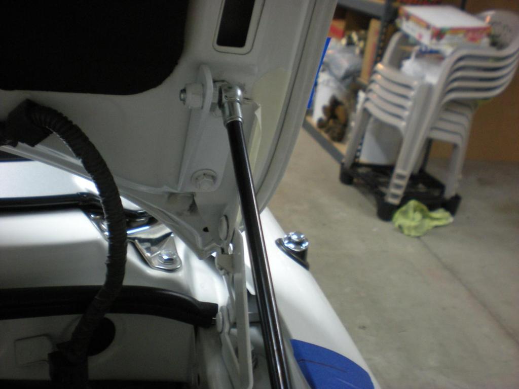
30 Did you put tape with alignment marks on the hinge and lid yet? I might have mentioned earlier that this is probably the most important step in making certain that you will be able to realign the lid the way it was before you started the install process. Using this method will help you keep the alignment of your frunk exactly where it is supposed to be after you loosen and retighten the brackets. (So you don t get confused by this picture, this is actually a picture from this same process that you will use when you install the engine hood brackets). Okay... I hope you get the idea. Now back to the frunk. Look for the two 12mm bolts that hold the frunk hood to the factory brackets. There are two of these bolts on each side. In the photo below we are looking at the passenger side and the black tube is for the window washing
 12mm bolt and use that same bolt to install the FD bracket, Use a drop of Blue Lock Tight just before inserting the bolt.")
31 fluid. Do not loosen these bolts yet. This photo was just for reference. The next photo is of the install of the bracket labeled FD. First remove the lower (closest to the driver s seat) 12mm bolt and use that same bolt to install the FD bracket, Use a drop of Blue Lock Tight just before inserting the bolt. Tighten it only until just about snug (so you have some room for adjustment. Then you will remove the upper bolt, swing the FD bracket into place and reinsert the 12mm bolt to tighten the new FD bracket to the existing factory bracket.

32 Here is a shot from the passenger side with the install of the the bracket lebeled FP. I removed the alignment tape for the sake of this photo. Do not remove any of the alignment tapes until you are certain that everything lines-up the way it is supposed to line-up.
 line up perfectly before your final tightening of bolts so that your frunk hood is positioned perfectly.")
33 This picture shows first installing the lower bolt. Once the lower bolt is reinstalled slide the bracket over, lign-up the holes and reinstall the upper 12mm bolt. Make sure the lines you drew on the masking tape (placed on the factory brackets) line up perfectly before your final tightening of bolts so that your frunk hood is positioned perfectly. Also remember to use lock tight on the 12mm bolts so they stay put. Here is what the bracket looks like installed on the driver s side:

34 Close the frunk hood and check your blue tape alignment lines to make sure everything is perfectly aligned. If the lines don t match-up on the tape, adjust the frunk lid/hood at the brackets until everything lines up perfectly. Do not move on to the next step until the frunk lid/hood is exactly where it is supposed to be. Tighten the 12mm bolts and then move on to the next step.

35 Next we ll install the gas struts. There is a little wire keeper located in the ball socket at the end of the gas strut. You remove that keeper by pushing the wire cage away from the ball end and once it is loose, you slide the wire keeper out of the hole. Do not lose that little keeper. Once lost, I have no idea where you will be able to buy a replacement.

36 Use brute force (if you have strong fingers) or use some pliers to hold onto the ball stud at the wide end of the gas strut and pull straight out. That will remove the ball stud. We won t need that ball stud for the install because we will use the metric one that we installed into the fender earlier. When installing the gas strut, install the fat end of the strut to the metric ball stud in the fender. I forgot to take a photo of this when doing the install, so here is a picture of what it would look like with the frunk surround plastic reinstalled:
37 Remove the ball stud from the skinny end of the strut ball socket and install it into the brackets -- one for the driver s side and one for the passenger s side. Use a 5/16-18 (half inch) nylon lock nut to secure the ball stud to each bracket. Note that the ball of each stud (driver side and passenger side) face inwards of the frunk and the SAE nut faces away from the frunk. This will make more sense when you look at the reference photos below. This is where you will need the two ½ (SAE) combination wrenches because the struts that you ordered have SAE not metric ball stud threads and that is why you are using the 5/16-18 nylon lock nuts. Once the ball studs are in place in the brackets, it is time to install the skinny end of the struts. Push in on the piston end of the strut (to collapse it a bit) and install the ball socket (located on the piston end) onto the ball stud in the bracket. Remember to reinstall the wire keepers into both ball sockets at the both ends of the gas struts. Here is a photo of the installed strut on the driver s side. Note that the ball stud and ball socket are on the inside of the bracket in the frunk installation. Here are several photos to show you positioning of ball studs and ball sockets.

38

39

40

41

42 Once everything is aligned and tightened, it s almost time to reinsert the modified frunk plastic surround. First you will want to remove the old prop rod that was used to hold the frunk lid up. It will come out fairly easy. You ll have to turn it and pull it a little. I wish I could explain it in words, but I can t figure-out how to write about it in a way that makes sense and it really is fairly easy to remove. I have confidence in you that you will be able to figure this out on your own. I mean, after all, even I figured it out. Okay. Once the old prop rod is out, reinstall the now modified frunk plastic surround and replace all those little push button fasteners. Before you close the frunk lid, check to make certain everything (like tools) are cleared out of the way and then slowly lower the frunk lid checking to make certain that everything clears easily before closing the lid completely. When I did this step I found that I needed to trim a little more plastic away from the passenger side frunk surround. My cut was too shallow by about a 16 th of an inch. I used my knife to slowly trim away a little plastic at a time, then reinstalled the surround and repeated the process for checking to make certain that everything was working properly and nothing was obstructing a clear path for the frunk lid to close. All clear and it worked perfectly. Take your time on this final step so if something is in the way, you can clear it out of the way to make certain that you don t damage your frunk lid. Here are photos of the completed frunk install.

43

44

45 The frunk install takes the longest and is probably the scariest because of having to cut the frunk plastic surround. I am not mechanically inclined. I took my time and it turned out great. If I can do this, anybody can do it. Next we ll move on to the install of the brackets and gas struts in the engine bay and lid. This will be much easier and a lot faster than the frunk. Installing the Engine Compartment/Hood Brackets The actual install process will be pretty much the same for the engine compartment/hood brackets as for the frunk. Put painter s tape on the hood and fenders, mark them with a straight line and cut the tape with your knife to give you reference marks for realigning the hood once the brackets are installed. Tape and mark the factory brackets on the hood for reference marks. Now you are set to begin the install process. BD and BP will be mounted in the engine compartment along the top of the fender lines. To refresh your memory, this is what BD and BP look like:

46 And this is what it looks like when they are installed first the Driver s Side:
47 And next the Passenger side:
48 Just like with the frunk installation, there is a bolt to remove that you then use to install the bracket. But there is also a hole already in place (thanks to Mr. T.) that you will need to use to install the second bolt to securely hold the bracket in place. This next photo shows you the place where the bolt and hole are located on the passenger s side. It will be the same on the driver s side

49 Mounting the bracket with the bolt you removed is no problem. Installing a second bolt through that hole... problem. But nothing that you can t easily address. This is where you will use one of the M6 1.0x20mm hex bolts to attach the bracket through that hole. I found it beneficial to unscrew the two Phillips head mounting screws on the tail light assembly so that you can gently swing the tail light assembly out a few inches to get your hand inside the fender-well and hold a M6 1.0 nylon lock nut in place. Then insert the bolt through the bracket and fender hole into the nut and tighten. Here is a photo of the tail light gently moved aside a few inches:

50 Once you have removed the two Phillips head screws that hold the tail light assembly in place, the only other thing to know is that there is a small plastic finger on the lower outside edge of the tail light assembly that will hold the tail light in place. You can remove the tail light completely by moving that little plastic finger out of its socket. If you do so, be very careful that you do not break that little plastic finger. That could get expensive. Anyway, by swinging the tail light assembly out just a few inches, you should have plenty of room to get a hand in there, to hold the nut so you can thread the new bolt. Tighten up bolts on the bracket, install the ball stud replace and screw-in the tail light assembly and that part of the install is done. Here are a couple of photos for reference. Note that the ball studs face in towards the engine and the gas strut s thick end is attached to the ball stud in the brackets on the fender.
51
52

53 Next, install the last two brackets, labeled ECD and ECP. These brackets will install on the engine compartment hood using the existing bolts that currently hold the hood to the hinges. Here is where these brackets need to be placed. Also, please note the position of the ball stud is facing away from the engine compartment. You will notice in these photos the use of regular masking tape that has lines drawn on it to be used for aligning the lid to the original position after the brackets are in place. If you are only installing brackets to the engine lid and you skipped reading the install instructions for the frunk, go back and read them now so you will know and understand the importance and process of using this tape process for alignment of your engine bay lid after installing the brackets. Do not skip this step as it is probably the most important step in the entire install process. Gee that statement sounds familiar. Okay... here are the pictures. First the Driver s side:

54

55 And then the passenger side:

56 Attach the gas struts and check your work. Here are some reference photos of the completed install.
57

58

59 Before you pull the tape off and test the hood to make sure everything works right, check to make certain that you also did these steps (identified in the write-up for the frunk). 1. Add a little extra grease to the ball sockets to make certain everything is lubed properly. 2. Make certain that you replace the little wire keepers after reconnecting ball studs to ball sockets. 3. Check alignment of the engine compartment hood using reference marks made earlier on hood hinges and around fender/hood enclosure. If the lines don t match-up perfectly, loosen the bolts and realign the hood, then tighten. 4. Fat end of the gas strut connects to the bracket on the fender and the skinny piston end of the gas struts attach to the bracket on the hood. 5. Remove the old engine hood prop rod. 6. Prepare yourself for lots of oooohs and aaaaahs when people see how cool your frunk and engine compartment hoods raise and lower so easily with your new gas struts.
INSTALLATION INSTRUCTIONS GRILLE GUARD RAM 1500 PART # 5058/5058-2
 INSTALLATION INSTRUCTIONS GRILLE GUARD PART # 5058/5058-2 PARTS LIST: Qty Description Qty Description 1 Grille Guard 8 12-1.75mm x 35mm Hex Bolts 2 Upper Frame Mounting s (for trucks without tow hooks
INSTALLATION INSTRUCTIONS DODGE RAM 2 & 4WD 1500 PART # P5058
 INSTALLATION INSTRUCTIONS 2009-13 DODGE RAM 2 & 4WD 1500 PART # P5058 PARTS LIST: Qty Description Qty Description 1 Grille Guard 12 12-1.75mm Hex Nuts 2 Upper Frame Mounting s (for trucks without tow hooks
THIS KIT INCLUDES: 8 M8-1.25X40MM BOLTS WITH WASHERS 8 M8-1.25X30MM BOLTS WITH WASHERS RIGHT AND LEFT HINGE
 Sal es@lambodoorscanada. com 2407A Kal adarave,ottawa,on K1V 8B9 THIS KIT INCLUDES: 8 M8-1.25X40MM BOLTS WITH WASHERS 8 M8-1.25X30MM BOLTS WITH WASHERS RIGHT AND LEFT HINGE 2 SHOCKS 565 PSI 2 SHOULDER
CORVETTE CORVETTE REV: Made in USA U.S. PATENT #6,808,223; #6,845,547; #7,140,075; #7,059,655 and other patents pending.
 CORVETTE 2005-2006 CORVETTE 2005-2007 REV: 7-2-07 Made in USA U.S. PATENT #6,808,223; #6,845,547; #7,140,075; #7,059,655 and other patents pending. Page 1 of 12 CORVETTE C6 2005-2007 THIS KIT INCLUDES:
TOOLS REQUIRED FOR INSTALLATION: AIR RACHET, GRINDER AND CUTTER.
 THIS KIT INCLUDES: 16 M8-1.25X30MM BOLTS WITH WASHERS 2 SHOCKS 565 PSI RIGHT AND LEFT HINGE ASSEMBLY 2 SHOULDER BOLTS 2 PINS TOOLS REQUIRED FOR INSTALLATION: AIR RACHET, GRINDER AND CUTTER. 7/23, 10MM,
INSTALLATION INSTRUCTIONS GRILLE GUARD 09-ON DODGE RAM PART #
 INSTALLATION INSTRUCTIONS GRILLE GUARD 09-ON DODGE RAM PART # PARTS LIST: Qty Description Qty Description 1 Grille Guard 8 12-1.75mm x 35mm Hex Bolts 2 Brackets (for trucks without 22 12mm x 30.1mm OD
Introduction. Rocky Mountain Westy Swing Away Carrier Kit Installation Instructions
 Rocky Mountain Westy Swing Away Carrier Kit Installation Instructions Introduction Thank you for purchasing the Rocky Mountain Westy Swing Away Carrier Kit. We pride ourselves in the products we develop
WARNING!! DO NOT LIFT DOORS UP WHEN THE HOOD IS OPEN. THE DOORS WILL HIT THE HOOD!
 WARNING!! DO NOT LIFT DOORS UP WHEN THE HOOD IS OPEN. THE DOORS WILL HIT THE HOOD! THIS KIT INCLUDES: 4 M8-1.25X30MM BOLTS WITH WASHERS 12 M8-1.25X40MM BOLTS WITH WASHERS 2 SHOULDER BOLTS WITH RIGHT AND
Installation for Full Size Polaris Ranger Crew Doors
 Installation for Full Size Polaris Ranger Crew Doors Order of Installation: Heater Doors Wiper on to Windshield Windshield Top & Back Panel Note: Most of the steps in these instructions need to be repeated
INSTALLATION MANUAL FRONT. See pages 2 and 3 of this manual for configuration options. Level of Difficulty. Product Photo (center section only)
") INSTALLATION MANUAL FRONT Level of Difficulty Moderate Product Photo (center section only) All hardware listed below will be provided with the bumpers center section. Additional hardware will be supplied
INSTALLATION MANUAL FRONT Level of Difficulty Moderate Product Photo (center section only) All hardware listed below will be provided with the bumpers center section. Additional hardware will be supplied
JK Rear Crusher Flares
 INSTALLATION INSTRUCTIONS INST-17-05-010_A JK Rear Crusher Flares IMPORTANT: Thank you for purchasing this Poison Spyder product. Please read through this entire document before proceeding with installation.
CORVETTE Page 1 of 12 CORVETTE C
 CORVETTE 2005-2006 Page 1 of 12 CORVETTE C5 1997-2004 THIS KIT INCLUDES: 8 M8-1.25X40MM BOLTS WITH WASHERS 8 M8-1.25X30MM BOLTS WITH WASHERS RIGHT AND LEFT HINGE ASSEMBLY WIRE LOOM 2 SHOCKS 565 PSI 2 SHOULDER
OTHER TOOLS MAY BE NEEDED DEPENDING ON YOUR VEHICLE.
 THIS KIT INCLUDES: 16 M8-1.25X40MM BOLTS WITH WASHERS 2 SHOCKS 720 PSI RIGHT AND LEFT HINGE ASSEMBLY 2 SHOULDER BOLTS 2 PINS TOOLS REQUIRED FOR INSTALLATION: AIR RACHET, GRINDER AND CUTTER. 10MM, 11MM,
RH-412 STEEL DOORS INSTALLATION INSTRUCTIONS
 RH-412 STEEL DOORS INSTALLATION INSTRUCTIONS By following the steps outlined below, the assembly, installation and adjustment of the steel doors, will be a simple process. Let s start with the Driver Side.
INSTALLATION INSTRUCTIONS RH 412 STEEL DOORS
 By following the steps outlined below, the assembly, installation and adjustment of the steel doors, will be a simple process. Let s start with the Driver Side. Note: Having the hood open makes the job
Hatchback Wing Riser Kit
 Hatchback Wing Riser Kit 2015-06-11 Thank you for purchasing this PERRIN product for your car! Installation of this product should only be performed by persons experienced with installation of aftermarket
8mm x 25mm "Z" Bolt Plates. (2) Tube Spacers. (2) 12mm Bolt Plates w/ Nut
 Tube Spacers. (2) 12mm Bolt Plates w/ Nut") PARTS LIST: 1 Grille Guard 10 12mm Lock Washers 1 Driver/Left Side Frame Mounting Bracket 8 12mm Hex Nuts 1 Passenger/Right Side Frame Mounting Bracket 2 10-1.50mm x 25mm Button Head Bolts 1 Driver/Left
PARTS LIST: 1 Grille Guard 10 12mm Lock Washers 1 Driver/Left Side Frame Mounting Bracket 8 12mm Hex Nuts 1 Passenger/Right Side Frame Mounting Bracket 2 10-1.50mm x 25mm Button Head Bolts 1 Driver/Left
Bushwacker Jeep Flat Style Fender Flares Front Pair
 Bushwacker Jeep Flat Style Fender Flares Front Pair Note: These instructions involve cutting parts of your vehicle. Please read all instructions prior to starting. Installation Time: 3-4 Hours Tools Required:
VIEWPOINT ALUMINUM RUNNING BOARD TOYOTA RAV4
 PARTS LIST: VIEWPOINT ALUMINUM RUNNING BOARD 1 Driver/Left Running Board 4 10-1.5mm x 50mm T-Bolt 1 Passenger/Right Running Board 12 10mm Plastic Retainers 1 Driver/Left Bracket 2 10-1.50mm x 40mm Hex
STEP 1 : DESTROYER FRONT BUMPER INSTALL GATHER YOUR TOOLS AND LAY OUT YOUR PARTS... *shorty bumper to show hardware* Tools Required:
 DESTROYER FRONT BUMPER INSTALL JL STEP 1 : GATHER YOUR TOOLS AND LAY OUT YOUR PARTS... Tools Required: - Utility knife - 11/16 Deep socket - Ratchet - 11/16 Crescent wrench - Ratchet Extension - 1/4 socket
Bushwacker Jeep Flat Style Fender Flares Rear Pair (JK Wrangler 2dr)
") Bushwacker Jeep Flat Style Fender Flares Rear Pair (JK Wrangler 2dr) Note: These instructions involve cutting parts of your vehicle. Please read all instructions prior to starting. Installation Time: 3-4
Bushwacker Jeep Flat Style Fender Flares Rear Pair (JK Wrangler 2dr) Note: These instructions involve cutting parts of your vehicle. Please read all instructions prior to starting. Installation Time: 3-4
STYLE BAR & TONNEAU COVER INSTALLATION
 STYLE BAR & TONNEAU COVER INSTALLATION INSTALLATION MANUAL: 2005 to '09 Mustang P/N: 10-8002-C12071B Saleen Performance, Inc. 1225 East Maple Rd., MI 48083 800-888-8945 www.saleen.com 1 IF YOU ARE NOT
======================================================================================== ( DR / DR) JK WRANGLER MOD RACK
 JK WRANGLER MOD RACK") (10984 4DR / 10982 2DR) JK WRANGLER MOD RACK INSTALLATION SHEET Important Notes: Some brands of windshield light brackets and snorkels may not be compatible with the 10984 MOD Rack System. Body lifts are
(10984 4DR / 10982 2DR) JK WRANGLER MOD RACK INSTALLATION SHEET Important Notes: Some brands of windshield light brackets and snorkels may not be compatible with the 10984 MOD Rack System. Body lifts are
JK Crusher Corners. *Includes ONE of the Hardware Kits (not both)
") INSTALLATION INSTRUCTIONS INST-18-05-020_A JK Crusher Corners IMPORTANT: Thank you for purchasing this Poison Spyder product. Please read through this entire document before proceeding with installation.
INSTALLATION INSTRUCTIONS INST-18-05-020_A JK Crusher Corners IMPORTANT: Thank you for purchasing this Poison Spyder product. Please read through this entire document before proceeding with installation.
Ford F150 Front Bumper
 2009-2011 Ford F150 Front Bumper Warning! Read the instructions completely before beginning the installation. Before tightening bolts, drilling or cutting where required, check to make sure that there
IMPORTANT: PLEASE RETAIN THIS INSTRUCTION MANUAL FOR FUTURE REFERENCE
 IMPORTANT: PLEASE RETAIN THIS INSTRUCTION MANUAL FOR FUTURE REFERENCE 005-07 Cadillac STS Classic 3D Z, Classic Dual Weave, Classic Mesh & Classic Black Mesh Grilles B 7 HR 3 STS Classic 3D Z Grille Part
Page 1 of 12 GENERAL INSTRUCTIONS KHJKK Installation
 Page 1 of 12 KHJKK PICTURE ABOVE IS THE UNIVERSAL KIT; YOUR KIT MAY BE DIFFERENT. THIS KIT INCLUDES: 8 M8-1.25X30MM BOLTS WITH WASHERS 8 M8-1.25X40MM BOLTS WITH WASHERS 2 PINS RIGHT AND LEFT HINGE ASSEMBLY
Hardware and Components:
 Hardware and Components: (A) 5/16 x 2 Hex Bolt (B) 5/16 x 2-1/4 Hex Bolt (C) 5/16 x 2-1/2 Hex Bolt (D) 4X 5/16 x 3/4 Hex Bolt (E) 4X 5/16 x 1-1/4 Hex Bolt (F) 11X 5/16 Flat Washer (G) 12X 5/16 Nylock Nut
AUDI A8 D3 REPLACING THE OUTSIDE DRIVER DOOR HANDLE
 AUDI A8 D3 REPLACING THE OUTSIDE DRIVER DOOR HANDLE The keyless entry system in the D3 is a great feature. If you have the car key fob in your pocket, putting your hand under the door handle will unlock
Thor Audi A4/S4 Skid Plate Installation Instructions
 Thor Audi A4/S4 Skid Plate Installation Instructions Parts List: 1 Aluminum Skid Plate 2 Aluminum Side Wings 10 10mm Flat Washers 3 8mm Flat Washers 3 8mm Speed Clips 2 10x40mm Bolts 3 8x35mm Bolts 2 Rivet-nuts
Driver/Left Top. Support Bracket
 PARTS LIST: 1 Grille Guard 8 10mm Lock Washers 1 Driver/Left Frame Bracket 8 10mm Hex Nuts 1 Passenger/Right Frame Bracket 2 8-1.25mm x 25mm Button Head Bolts 1 Driver/Left Bottom Support Bracket 2 8mm
GRILLE GUARD SPRINTER VAN (EXCLUDES X4) INCLUDES MERCEDES, FREIGHTLINER AND DODGE PARTS LIST:
 INCLUDES MERCEDES, FREIGHTLINER AND DODGE PARTS LIST:") PARTS LIST: 1 Grille Guard 8 12mm Hex Nuts 1 Driver/Left Side Frame Mounting Bracket 2 10-1.50mm x 25mm Button Head Bolts 1 Passenger/Right Side Frame Mounting Bracket 4 10mm x 20mm OD x 2mm Flat Washers
PARTS LIST: 1 Grille Guard 8 12mm Hex Nuts 1 Driver/Left Side Frame Mounting Bracket 2 10-1.50mm x 25mm Button Head Bolts 1 Passenger/Right Side Frame Mounting Bracket 4 10mm x 20mm OD x 2mm Flat Washers
INSTALLATION INSTRUCTIONS
 TEL -866-XANATOS INSTALLATION INSTRUCTIONS PART#: 7D5000SS\7D500A GRILL GUARD FOR DODGE SPRINTER 07-09 PARTS LIST: 8 6 Grille Guard Driver/Left Frame Mounting Passenger/Right Frame Mounting Driver/Left
Chevy Colorado. INSTALLATION GUIDE Front Bumper
 Chevy Colorado INSTALLATION GUIDE Front Bumper FIG 1A First, we ll start by removing the small allen bolts from the inside fender wells that hold the stock front bumper in place. FIG 1B You will also need
JK Brawler Rockers. *Includes ONE of the Hardware Kits (not both)
") INSTALLATION INSTRUCTIONS INST-17-08-200_A JK Brawler Rockers IMPORTANT: Thank you for purchasing this Poison Spyder product. Please read through this entire document before proceeding with installation.
INSTALLATION INSTRUCTIONS INST-17-08-200_A JK Brawler Rockers IMPORTANT: Thank you for purchasing this Poison Spyder product. Please read through this entire document before proceeding with installation.
ABM International, Inc.
 ABM International, Inc. Lightning Stitch required 1 1.0: Parts List head and motor assembly (Qty. 1) Reel stand (Qty. 1) Needle bar frame clamp (Qty. 1) Motor drive (Qty. 1) 2 Cable harness with bracket
2 SHOULDER BOLTS RIGHT AND LEFT HINGE USE 4 EXISITING DOOR BOLTS TOOLS REQUIRED FOR INSTALLATION: AIR RACHET, GRINDER AND CUTTER.
 Page 1 of 12 NISSAN 350Z 2003-2004 THIS KIT INCLUDES: 8 BOLTS WITH WASHERS 2 SHOCKS 780 PSI 2 PINS 2 SHOULDER BOLTS RIGHT AND LEFT HINGE USE 4 EXISITING DOOR ASSEMBLY BOLTS TOOLS REQUIRED FOR INSTALLATION:
Barricade Trail Force HD Rear Bumper w/ Tire Carrier installation (07-16 Wrangler JK)
") Barricade Trail Force HD Rear Bumper w/ Tire Carrier installation (07-16 Wrangler JK) Installation Time: 2-3 Hours Tools Required: Tire iron Ratcheting socket set (ratchet plus 13, 16, 19mm sockets) Open
Barricade Trail Force HD Rear Bumper w/ Tire Carrier installation (07-16 Wrangler JK) Installation Time: 2-3 Hours Tools Required: Tire iron Ratcheting socket set (ratchet plus 13, 16, 19mm sockets) Open
Please read BOTH these Installation Instructions and the General Instructions before attempting to install or operate this equipment.
 Please read BOTH these and the General Instructions before attempting to install or operate this equipment. 1. Blue Ox towing products and accessories are intended to be installed by Blue Ox Dealers who
Assembly and installation help
 Assembly and installation help A supplement to the directions The Purpose of this tutorial is to expand (not replace) upon the directions that come with the system and to help provide shortcuts, the first
JK TrailGate JK TrailGate
 INSTALLATION INSTRUCTIONS INST-17-66-010_A JK TrailGate IMPORTANT: Thank you for purchasing this Poison Spyder product. Please read through this entire document before proceeding with installation. If
Polaris General Doors #06016 Installation & Operations Manual Fits Polaris General
 Polaris General Doors #06016 Installation & Operations Manual Fits Polaris General Before You Start: Please familiarize yourself with all the steps before beginning assembly. Compatibility Info: This Door
YJ DeFenders. These installation instructions apply to the following Poison Spyder products:
 INSTALLATION INSTRUCTIONS INST-13-02-070_A YJ DeFenders IMPORTANT: Thank you for purchasing this Poison Spyder product. Please read through this entire document before proceeding with installation. If
HEAVY DUTY 11 STEEL CABINET
 HEAVY DUTY STEEL CABINET ASSEMBLY INSTRUCTIONS ONE DRAWER BASE CABINET 05-206 Parts List Part No Description Qty Image ONE DRAWER BASE CABINET Part No Description Qty Image SB- Cabinet Body EH-0 Euro Hinge
Please read BOTH these Installation Instructions and the General Instructions prior to installing or operating this equipment.
 Attachment Tab Height: 13 Attachment Tab Width: 24 Please read BOTH these and the General Instructions prior to installing or operating this equipment. Serial Number 1. Blue Ox towing products and accessories
MODULAR BUMPER INSTALLATION MANUAL
 MODULAR BUMPER INSTALLATION MANUAL Parts List* 1 Center section 1 Side extension, passenger / right 1 Side extension, driver / left 1 Side cap, passenger / right 1 Side cap, driver / left 1 Brush guard,
JK Rear Inner Fenders
 INSTALLATION INSTRUCTIONS INST-17-05-080_A JK Rear Inner Fenders IMPORTANT: Thank you for purchasing this Poison Spyder product. Please read through this entire document before proceeding with installation.
TYGER GUARD. Parts List BEFORE INSTALLATION WARNING TG-GD6D /7. Tyger Guard. Tube Brackets (Bull Bar) passenger or driver side
 passenger or driver side") TYGER GUARD TM BEFORE INSTALLATION TG-GD6D60068 READ INSTRUCTIONS CAREFULLY BEFORE STARTING INSTALLATION. REMOVE CONTENTS FROM BOX AND VERIFY ALL PARTS ARE PRESENT. ASSISTANCE IS RECOMMENDED. CUTTING IS
TYGER GUARD TM BEFORE INSTALLATION TG-GD6D60068 READ INSTRUCTIONS CAREFULLY BEFORE STARTING INSTALLATION. REMOVE CONTENTS FROM BOX AND VERIFY ALL PARTS ARE PRESENT. ASSISTANCE IS RECOMMENDED. CUTTING IS
TOOL LIST FOR TAILGATE HIDDEN LATCH & LINK ASSY FOR FORD FLARESIDE TRUCKS
 TOOL LIST FOR TAILGATE HIDDEN LATCH & LINK ASSY FOR 53-87 FORD FLARESIDE TRUCKS Vise Grip Clamps C-clamps Sharpie Marker Ball Peen Hammer Center Punch 3/8 or 1/2 Drill 5/32, 7/32, 9/32, and 3/8 Drill Bits
(2) 25mm x 20mm x 5mm Adhesive Backed Foam Pads. 100mm x 50mm x 1.0mm Adhesive Backed Foam. (2) Spacer Plates. Passenger/Right Side Frame Mounting
 25mm x 20mm x 5mm Adhesive Backed Foam Pads. 100mm x 50mm x 1.0mm Adhesive Backed Foam. (2) Spacer Plates. Passenger/Right Side Frame Mounting") PARTS LIST: 1 Grille Guard 10 12mm Lock Washers 1 Driver/Left Frame Mounting 16 12mm x 32mm OD x 3mm Flat Washers 1 Passenger/Right Frame Mounting 8 12mm Hex Nuts 1 Driver/Left Side Top Support 2 10-1.50mm
PARTS LIST: 1 Grille Guard 10 12mm Lock Washers 1 Driver/Left Frame Mounting 16 12mm x 32mm OD x 3mm Flat Washers 1 Passenger/Right Frame Mounting 8 12mm Hex Nuts 1 Driver/Left Side Top Support 2 10-1.50mm
Miata Air Radical Splitter/Protector
 Miata Air Radical Splitter/Protector Year: 2004-2005 MazdaSpeed Item: TDR-04M125 Thank you for purchasing the Track Dog Racing Radical. The Air Splitter is designed to help protect the factory MazdaSpeed
JK Front Crusher Flares
 INSTALLATION INSTRUCTIONS INST-17-03-030_A JK Front Crusher Flares IMPORTANT: Thank you for purchasing this Poison Spyder product. Please read through this entire document before proceeding with installation.
BX3615. Subaru Impreza WRX (Include STI) Subaru 2012 Impreza Premium 2010 Outback Sport Installation Instructions Attachment Tab Height: 15
 Subaru 2012 Impreza Premium 2010 Outback Sport Installation Instructions Attachment Tab Height: 15") 1. Blue Ox towing products and accessories are intended to be installed by Blue Ox Dealers who are familiar with our products and have the equipment and knowledge necessary to do fit work. If needed, Blue
1. Blue Ox towing products and accessories are intended to be installed by Blue Ox Dealers who are familiar with our products and have the equipment and knowledge necessary to do fit work. If needed, Blue
General Prisoner Transport Install Instructions PT-2-INST
 General Prisoner Transport Install Instructions PT-2-INST 50 or 60 high x 80, 100 & 120 inch long / Double Compartment Inserts Also refer to PT-A-3XX instructions for vehicle specific mounting measurements
FRONT BUMPER INSTALLATION INSTRUCTIONS Toyota 4Runner
 Aluminess Products Inc 9402 Wheatlands Ct. #A Santee, CA 92071 619-449-9930 FRONT BUMPER INSTALLATION INSTRUCTIONS 2003-2009 Toyota 4Runner Please read before beginning Stainless steel hardware may bind
INSTALLATION INSTRUCTIONS 3 ROUND & 4 OVAL SIDEBAR (90-DEG BENT END) DODGE RAM MEGA CAB PART NUMBER SB1214S SB1214B
 DODGE RAM MEGA CAB PART NUMBER SB1214S SB1214B") INSTALLATION INSTRUCTIONS PART NUMBER SB1214S SB1214B PARTS LIST: Qty Description Qty Description 1 Driver/Left Sidebar 4 12mm x 32mm OD x 3mm Flat Washers 1 Passenger/Right Sidebar 4 12mm Lock Washers
INSTALLATION INSTRUCTIONS PART NUMBER SB1214S SB1214B PARTS LIST: Qty Description Qty Description 1 Driver/Left Sidebar 4 12mm x 32mm OD x 3mm Flat Washers 1 Passenger/Right Sidebar 4 12mm Lock Washers
1104. Clean up the door striker plates with a hand grinder using a wire brush and WD-40.
 Chapter 31 - Misc. Putting VW Back Together (Video Clip 31) 1104. Clean up the door striker plates with a hand grinder using a wire brush and WD-40. 1105. Install both door striker plates on the VW body
Rugged Ridge Body Armor Guard Kit, 5 Pieces, Black (07-Current JK 4-door)
") Rugged Ridge Body Armor Guard Kit, 5 Pieces, Black (07-Current JK 4-door) Installation Time: 60 Minutes Tools Required: Notes: Phillips head screwdriver 3/8 socket or Flat head screwdriver 1/2 socket 7
Rugged Ridge Body Armor Guard Kit, 5 Pieces, Black (07-Current JK 4-door) Installation Time: 60 Minutes Tools Required: Notes: Phillips head screwdriver 3/8 socket or Flat head screwdriver 1/2 socket 7
16 STEEL CABINET HEAVY DUTY
 HEAVY DUTY 16 STEEL CABINET ASSEMBLY INSTRUCTIONS SIX DRAWER BASE CABINET 12-2013 Parts List Part No Description Qty Image SIX DRAWER BASE CABINET Part No Description Qty Image SB-1 Cabinet Body 1 SLD-01
INSTALLATION INSTRUCTIONS
 AUTOMOTIVE PRODUCTS, INSTALLATION INSTRUCTIONS PLATINUM 4 OVAL STEP BAR (90 BENT END) APPLICATION: 2010-2015 Dodge Ram 2500/3500 Mega Cab PART NUMBER: 21-3570, 21-3575, 23-3570, 23-3575, 25-3570, 25-3575,
Miata Radical Air Splitter/Protector
 Miata Radical Air Splitter/Protector Year: 1990-1997 with Factory R-Package Lip Item: TDR-90M125 Thank you for purchasing the Track Dog Racing Radical Air Splitter. The Air Splitter is designed to help
BABY WOLF LOOM. Assembly Instructions for Knocked-Down Looms
 BABY WOLF LOOM Assembly Instructions for Knocked-Down Looms BEFORE YOU BEGIN Please read through the directions before beginning to assemble your loom. Unpack the loom parts carefully. Do not throw away
INSTALLATION INSTRUCTIONS KK-K9-C12-K CHEVY IMPALA
 INSTALLATION INSTRUCTIONS KK-K9-C12-K 2000-2005 CHEVY IMPALA READ ALL INSTRUCTIONS PRIOR TO INSTALLATION TOOLS REQUIRED: Power Drill Drill bits1/4 and 5/32 7/l6 wrench and socket 15,18 and\or 19mm socket
WARNING. Bolt Torque Specifications Torque in Foot-Pounds for Inch Bolts Bolt Size Grade 5 Grade 8
 1. Blue Ox towing products and accessories are intended to be installed by Blue Ox Dealers who are familiar with our products and have the equipment and knowledge necessary to do fit work. If needed, Blue
INSTALLATION INSTRUCTIONS 3 BULL BAR 99-04, 04 "HERITAGE" F-150/250LD 2WD, 97-04, 04 "HERITAGE" 4WD WD EXPEDITION/ WD EXPEDITION PART
 INSTALLATION INSTRUCTIONS 3 BULL BAR PART #B-F1971;B-F2971 PARTS LIST: 1 Bull Bar 2 12-1.75mm x 130mm x 40mm Hex Bolts 1 Driver/Left Mounting Bracket 4 12-1.75mm x 35mm Hex Bolts 1 Passenger/Right Mounting
Installation Instructions for FC2 & FC15 Forward Controls for the Super Magna
 Installation Instructions for FC2 & FC15 Forward Controls for the Super Magna It is highly recommended that you use a thread lock compound such as Loctite brand on all threads to keep them from vibrating
Rugged Ridge Front Bumper Winch Plate JK
 Rugged Ridge Front Bumper Winch Plate 13-17 JK Note: These instructions involve cutting parts of your vehicle. Please read all instructions prior to starting. Installation Time: 2-3 Hours Tools Required:
JK FRONT FENDER FLARE INSTALLATION INSTRUCTIONS
 JK FRONT FENDER FLARE INSTALLATION INSTRUCTIONS TOOLS NEEDED 3/16 Allen Wrench 1/2 Socket or wrench 10mm Socket Flat head screwdriver HARDWARE 5/16 x 3/4 button heads (14) 5/16 x 1 button heads (8) 5/16
General Features. Low Profile. The SMART BOXX stands only 1.5 off of the bed of your truck so cargo space is maximized
 General Features Low Profile. The SMART BOXX stands only 1.5 off of the bed of your truck so cargo space is maximized Two Sizes Short Box :74 L X 47 W X 7 T and Long Box 92 L X 47 W X 7 T All Aluminium
Please read BOTH these Installation Instructions and the General Instructions prior to installing or operating this equipment.
 2012-14 Chevy Captiva Sport Attachment Tab Height: 21-1/2 Serial Number Attachment Tab Width: 18-1/2 Please read BOTH these and the General Instructions prior to installing or operating this equipment.
 INSTRUCTION BOOKLET #C0 Watch step by step installation instructions at: https://www.wallbedsbywilding.com/wallbed-installation-studio-series/ WARNING! ALL MURPHY/WALLBED SYSTEMS CONTAIN STORED ENERGY.
WARNING Mercedes Benz GL550 4Matic Installation Instructions BX1992. Serial Number
 Please read BOTH these and the General Instructions before attempting to install or operate this equipment. 1. Blue Ox towing products and accessories are intended to be installed by Blue Ox Dealers who
INSTALLATION INSTRUCTIONS
 TEL:1-866-XANATOS INSTALLATION INSTRUCTIONS FOR 07-13 CHEVY SILVERADO 1500 PART#RU-CHSI07-B PARTS LIST: 1 Main Body 28 12mm x 37mm OD x 3mm Large Flat Washers 1 Driver/Left Brush Guard 8 12-1.75mm x 40mm
The Bowflex Revolution XP Home Gym Assembly Instructions. P/N: Rev ( /0 )
") P/N: 001-7057 Rev ( /0 ) The Bowflex Revolution XP Home Gym Assembly Instructions 2 Table of Contents Before You Start... 2 Tools You Will Need / Hardware Contents... 3 Box Contents... 6 Assembling Your
P/N: 001-7057 Rev ( /0 ) The Bowflex Revolution XP Home Gym Assembly Instructions 2 Table of Contents Before You Start... 2 Tools You Will Need / Hardware Contents... 3 Box Contents... 6 Assembling Your
BMW X5 OEM RUNNING BOARD PART#SBBW
 INSTALLATION INSTRUCTIONS 2014-2016 BMW X5 OEM RUNNING BOARD PART#SBBW-146-74 QTY HARDWARE 1 Driver Side OEM Running Board 1 Passenger Side OEM Running Board 8 Rivet Pin 1 Page Step 1: Verify all parts
Hardware and Components:
 Hardware and Components: (A) 4X 5/16 x 1 Carriage Bolt (B) 2X 5/16 x 2-1/4 Carriage Bolt (C) 2X 5/16 x 3-1/4 Hex Bolt (D) 2X 5/16 x 3/4 Hex Bolt (E) 2X 5/16 x 1-1/4 Hex Bolt (F) 5/16 x 2-1/4 Hex Bolt (G)
GlideRite Retractable Cover System For Hot Spot Spas (SE & SLX only)
") List of Contents Quantity Description 12 #10 x 1 ½ Flat Head Phillips Screw (see pg. 2) 2 #10 x ½ Pan Head Phillips Screw (see pg. 2) 8 ¼ x 2 ½ Lag Bolt (see pg. 2) 7 ¼ 20 x 5 / 8 Hex Head Bolt (see pg.
List of Contents Quantity Description 12 #10 x 1 ½ Flat Head Phillips Screw (see pg. 2) 2 #10 x ½ Pan Head Phillips Screw (see pg. 2) 8 ¼ x 2 ½ Lag Bolt (see pg. 2) 7 ¼ 20 x 5 / 8 Hex Head Bolt (see pg.
Customer Notice: Congratulations again on your SawStop purchase, and thank you! -SawStop Tualatin, OR
 Customer Notice: Congratulations on the purchase of this Sliding Crosscut Attachment. As the owner of a SawStop saw, you are familiar with our high standards for quality, fit and finish. Different from
Technicians of Terror. This is the air valve we make to use with our air
 These are pictures of our scissor prop. Technicians of Terror http://www.halloweenfear.com/scissorprop.html props. This is the air valve we make to use with our air This pictures the duel door closer cylinders
Removing outter components
 Y Axis Motor Replacement Replacing the Y axis motor is a process that requires the individual to be somewhat mechanically inclined and can follow detailed instructions. If any of the following steps are
INSTALLATION INSTRUCTIONS
 Do not attempt to install this product on any vehicle other than the one it is designed for and listed above! Parts List 10 3/8 X 1 1/4 Hex Bolt 10 3/8 Lock Washer 4 3/8 Hex Nut 4 3/8 Flat Washer 2 3169)
INSTALLATION INSTRUCTIONS GRILLE GUARD CHEVY TAHOE / AVALANCHE 1500/ SUBURBAN 1500 PART # /502795
 (W) INSTALLATION INSTRUCTIONS GRILLE GUARD PART # 502794/502795 PARTS LIST: 1 Grille Guard 2 12-1.75mm x 140mm Hex Bolts 2 Frame Mounting Brackets 8 12-1.75mm x 30mm Hex Bolts 2 Lower Support Brackets
Tools Required: - Utility knife - 11/16 Deep socket - Ratchet - 11/16 Crescent wrench - Ratchet Extension - 1/4 socket - Electrical tape
 DESTROYER FRONT BUMPER INSTALL JL STEP 1 : GATHER YOUR TOOLS AND LAY OUT YOUR PARTS... Tools Required: - Utility knife - 11/16 Deep socket - Ratchet - 11/16 Crescent wrench - Ratchet Extension - 1/4 socket
INSTRUCTION BOOKLET #34. For Wallbed models: KING SIZE SIERRA WITH STORAGE HEADBOARD
 For Wallbed models: KING SIZE SIERRA WITH STORAGE HEADBOARD INSTRUCTION BOOKLET #34 WARNING! ALL MURPHY/WALLBED SYSTEMS CONTAIN STORED ENERGY. FAILURE TO USE AND FOLLOW THESE INSTRUCTIONS DURING THE INSTALLATION
WARNING. BX Ford Explorer With Adaptive Cruise Control & Eco Boost Installation Instructions
 Please read BOTH these and the General Instructions before attempting to install or operate this equipment. 1. Blue Ox towing products and accessories are intended to be installed by Blue Ox Dealers who
Please read BOTH these Installation Instructions and the General Instructions prior to installing or operating this equipment.
 (No Turbo) Attachment Tab Height: 14 Serial Number Attachment Tab Width: 18 Please read BOTH these and the General Instructions prior to installing or operating this equipment. 1. Blue Ox towing products
Be sure any accessory used will fit with the soft upper doors before installing. Not all accessories will be compatible.
 Company Name: Spike Power Sports Vehicle Name: Polaris General 2P Product Description: Soft Upper Doors Part Number: 58-1600 Revision: R01 09/19/2018 Contents: 655 Elm Ridge Ave, Canal Fulton OH, 44614
Please read BOTH these Installation Instructions and the General Instructions prior to installing or operating this equipment.
 Serial Number BX3620 Please read BOTH these and the General Instructions prior to installing or operating this equipment. 1. Blue Ox towing products and accessories are intended to be installed by Blue
The Useless Machine. DIY Soldering Edition. Instruction Guide v0004
 The Useless Machine DIY Soldering Edition Instruction Guide v0004 TM For the best outcome, follow each step in order. We recommend reading this guide entirely before you get started. Tools required: Soldering
Triplex Instructions for Packing and Unpacking
 2-8-8-2 Triplex Instructions for Packing and Unpacking It is recommended that you review all these instructions before removing the engine or tender from the poly foam container. www.mthtrains.com Table
Installing a genuine HoodLift on a Jeep TJ
 Installing a genuine HoodLift on a Jeep TJ 1997-2006 To print a full-color version of these instructions go to www.hoodlift.com/products.html. Scroll down to the TJ HoodLift and click on the TJ HoodLift
INSTALLATION INSTRUCTIONS
 INSTALLATION INSTRUCTIONS SPORTSMAN WINCH MOUNT GRILLE GUARD APPLICATION: 2016-2018 Toyota Tacoma PART NUMBER: 40-93885, 45-93880, 46-23885 ITEM QUANTITY DESCRIPTION TOOLS NEEDED 1 1 WINCH TRAY 15MM SOCKET
INSTALL INSTRUCTIONS KK & KK KWIK-KIT PRISONER TRANSPORT INSERT FORD and CHEVY VAN PRISONER TRANSPORT
 INSTALL INSTRUCTIONS KK-100-03 & KK-120-03 KWIK-KIT PRISONER TRANSPORT INSERT FORD and CHEVY VAN PRISONER TRANSPORT TOOLS REQUIRED: ¼ & 3/8 Ratcheting Wrenches ¼ & 3/8 Air Ratchets (recommended) 3/8 Impact
Paco Motorsports Strong Arms X
 Paco Motorsports Strong Arms 13-101X Thanks for purchasing our Strong Arms. These braces reinforce the frame horns that support the engine and transfer all of the cornering and road impact loads into the
model tsa-sa48 Sliding Crosscut Table installation guide
 model tsa-sa48 Sliding Crosscut Table installation guide A Note About Color Variations Among Anodized Aluminum Components Congratulations on the purchase of this SawStop Sliding Crosscut Table. We at SawStop
Chapter 32 - Hood, Deck, Fenders & Running Boards Installation (Video Clip 32)
") Chapter 32 - Hood, Deck, Fenders & Running Boards Installation (Video Clip 32) 1166. Polish the hood handle with chrome polish and then install the handle onto the hood. 1167. Use a 10mm socket and from
Chapter 32 - Hood, Deck, Fenders & Running Boards Installation (Video Clip 32) 1166. Polish the hood handle with chrome polish and then install the handle onto the hood. 1167. Use a 10mm socket and from
INSTALL INSTRUCTIONS
 Jeep JK Rear Corner Skins Product : JK200,JK201,JK202,JK203 Applica on : 2007+ Jeep Wrangler JK ( 2 Door and 4 Door ) Page ( 1 of 6 ) I WARNING Read the instruc ons completely before beginning installa
GlideRite Retractable Cover System For HotSpring & Tiger River Spas (except Classic & pre-2000 Landmark Spas)
") List of Contents Quantity Description 12 #10 x 1 ½ Flat Head Phillips Screw (see pg. 2) 2 #10 x ½ Pan Head Phillips Screw (see pg. 2) 8 ¼ x 2 ½ Lag Bolt (see pg. 2) 7 ¼ 20 x 5 / 8 Hex Head Bolt (see pg.
List of Contents Quantity Description 12 #10 x 1 ½ Flat Head Phillips Screw (see pg. 2) 2 #10 x ½ Pan Head Phillips Screw (see pg. 2) 8 ¼ x 2 ½ Lag Bolt (see pg. 2) 7 ¼ 20 x 5 / 8 Hex Head Bolt (see pg.
08+ KAWASAKI KLR PD NERF
 08+ KAWASAKI KLR PD NERF 0505-1299 Before you begin, place the bike on a hard level surface where you have room to work. Lay out the parts included in this kit and compare to the parts list on page 5 of
 INSTRUCTION BOOKLET #C10 Watch step by step installation instructions at: https://www.wallbedsbywilding.com/wallbed-installation-studio-series/ WARNING! ALL MURPHY/WALLBED SYSTEMS CONTAIN STORED ENERGY.