Lateral Load-Bearing Capacity of Nailed Joints Based on the Yield Theory Theoretical Development
|
|
|
- Laurence Bishop
- 6 years ago
- Views:
Transcription


1 United States Department of Agriculture Forest Service Forest Products Laboratory Research Paper FPL 469 Lateral Load-Bearing Capacity of Nailed Joints Based on the Yield Theory Theoretical Development Petter Aune Marcia Patton-Mallory
2 Abstract Contents A European-based yield theory using a material science approach predicts the ultimate lateral load of nailed joints with different joint configurations. The original theory is presented here and extended to include steel-to-wood joints and joints with a layer of insulation (or gap) between joint members. Formulas provide ultimate load for wood-to-wood and steel-to-wood joints and joints with unequal wood strength, A final formula represents the relationship between the wood s embedding stress and deformation not on the traditional assumption of plasticity, but as a fourth-root curve. Keywords: Nail, yield theory, nail joints, lateral load, ultimate load Page Background... 1 Nailed Joints... 1 Earlier Work on the Yield Theory... 2 Development of the Yield Model... 3 Wood Members with Similar Embedding Strengths... 3 Wood Members with Different Embedding Strengths 10 Sheathing and Insulation Members Embedding Stress-Deflection Relationship Discussion Member Thickness Nailhead Fixity Steel Side Plates Insulation Layer Different Embedding Strengths Fourth-Root Curve summary Literature Cited Additional Literature March 1986 Aune, Petter; Patton-Mallory, Marcia. Lateral load-bearing capacity of nailed joints based on the yield theory: Theoretical development. Res. Pap. FPL 469. Madison, WI. U.S. Department of Agriculture, Forest Service, Forest Products Laboratory; p. A limited number of free copies of this publication are available to the public from the Forest Products Laboratory. One Gifford Pinchot Drive. Madison. WI Laboratory publication\ are sent to over 1,000 libraries in the United States and elsewhere. The Laboratory is maintained in cooperation with the University of Wisconsin.
3 Lateral Load-Bearing Capacity of Nailed Joints Based on the Yield Theory Theoretical Development Petter Aune, 1 Associate Professor The University of Trondheim, The Norwegian Institute of Technology, Trodheim, Norway Marcia Patton-Mallory, Engineer Forest Products Laboratory, Madison, WI Background The ultimate lateral load of a nailed timber joint can be derived by use of a theory of yielding which assumes plasticity in both the wood and the fastener; this we refer to as the yield theory. The general yield theory has existed since the 1940 s. It is currently used in Europe where it provides a rational basis for setting design criteria for nailed joints. The validity of the method of derivation has been confirmed by experimental investigations (Aune 1966; Meyer 1957; Möller 1950; Siimes and others 1954). In several European countries (CIB 1983), the code values for lateral load-bearing capacity are based on the yield theory. Use of the yield theory by code writers and researchers in North America would promote international adoption of a consistent method and promote use of a uniform method of analysis for joints containing nails, bolts, or lag screws. The purpose of this report is to present the yield theory as a rational basis for predicting yield load of nailed joint configurations commonly found in the United States. We show how the yield theory applies to two- and three-member joints with either all-wood members or wood members combined with steel members or wood-based sheathing materials. Then, we extend application to wood members of unequal embedding strength. Here, for the first time, we present the formulas for joints having an interlayer gap (or layer of insulation) between surfaces, and for steel-to-wood joints. Finally, we substitute a fourth-root curve for the original plastic embedding relationship. Derivation of this last formula makes possible an extension of the yield theory to joint deformations. A companion report (Aune and Patton-Mallory 1986) provides experimental verification of the yield theory developed in this report. Nailed Joints Although the use of nails goes far back in history, it was after the industrial manufacture of nails began in the last century that nails became one of the most common fasteners in wooden houses, structural timber constructions, and wooden assemblies of all kinds. Improved methods of engineering design soon showed the need for research into joint behavior and joint design. Tests on nailed joints were among the early investigations performed at the Forest Products Laboratory (Wilson 1917). Since the mid-1950 s many countries have conducted extensive research in nail fasteners. Particular investigations were required in particular countries because of the differences in building practices, nail types and wood species in use. Until recently even the test methods used in these investigations were often unique to each country. Various theories have been used to derive nailed-joint behavior; the result is an even greater variation in design criteria than the differences in the test methods alone could justify. 1 Visiting scientist at FPL, October 1981-June 1982.
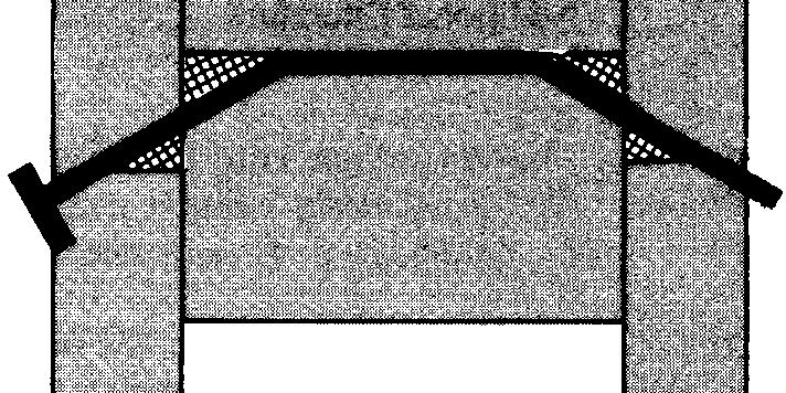
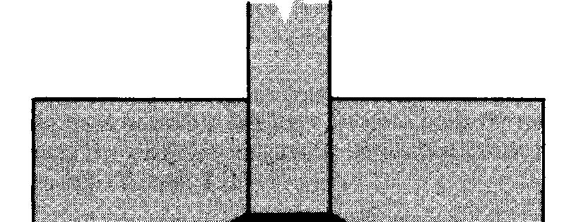
4 In 1979, Ehlbeck made a comprehensive survey of the status of nailed joint design in wood and in wood-based products. He summarized the research of the previous 20 to 30 years concerning different theories of joint performance, design criteria, national codes, and test methods. An extensive reference list and a list of additional relevant literature make his investigation complete and useful. Ehlbeck states that research should now be aimed at uniform conclusions instead of performing isolated research within the national boundaries. Uniform worldwide standards and codes based on international agreement in the light of the advanced thinking in materials and construction may result from this approach. Now that the need for standardization is appreciated, we believe the yield theory can contribute substantially to this goal. Earlier Work on the Yield Theory As early as 1941, the yield theory originated with the work of the Danish scientist, K. W. Johansen, who first applied the theory to timber fasteners (Johansen 1941). Eight years later he published a shortened version of his original paper in English (Johansen 1949). Some of his investigations on nailed joints were unfinished, and for years the results remained unpublished; eventually, Larsen (1977) completed and published this work. Referring to his studies of bolted joints, Johansen stated that load-bearing behavior is composed of two effects: 1. The dowel effect of the bolt which depends on the bolt s resistance to bending and the resistance of the wood to crushing. Subsequently, Siimes et al. (1954), Mack (1960), and Aune (1966) have verified the yield theory for nailed joints by experiments. Meyer (1957) discussed the effect of friction. The contribution of friction is not usually taken into account in joint design. Larsen and Reestrup (1969) investigated lag screw joints. They found conditions in a laterally loaded screw joint differed slightly from those in a bolted joint because of different embedding values along the screw. Furthermore, the yielding might occur in the shank as well as in the threads, so that different values of the yield moment M y had to be considered. Formulas for the load-bearing capacity were derived and verified by tests. Norén (1974) summarized the different formulas developed for different kinds of timber connectors. Larsen (1973) offered a rationale supporting the use of the yield theory in the codes of the Scandinavian countries. Later (1979), he reported the theoretical background and the approximations for bolted joints given in the proposal for the CIB Structural Timber Design Code (1983). Most recently, McLain and Thangjitham (1983) surveyed the yield theory as it applies to bolted joints typical of American construction practices. Their analysis includes a model modified to account for the lack of end fixity in bolted joint tests. The work of the scientists and engineers discussed above contributed to the yield theory presented in this paper. In addition to the list of actual citations, we include a supplementary list of additional literature on the subject of nailed joints. 2. The tensional effect of the bolt which depends on the bolt s resistance to tension and the presence of friction between abutting surfaces. Johansen analyzed the dowel joint (fig. 1) in detail. He assumed that no axial tension occurred in the fastener and, thus, no frictional contribution to the lateral load-bearing capacity. He also assumed the stress-deflection relationships of the dowel in bending and of the wood in embedding were ideally plastic, as shown in figure 2. Based on these assumptions, Johansen obtained the load-bearing capacity for single- and double-shear joints. The expressions are rather simple and each is related to a particular mode of failure. He verified both the assumptions and the formulas by tests. Möller (1950) applied the basic yield theory to nailed joints in single and double shear. His investigation included symmetrical and nonsymmetrical two-member joints and symmetrical three-member joints. He also considered the effect of having joint members of different embedment strengths. Although the principles had been introduced by Johansen 10 years earlier, the yield theory concerning nailed joints is quite often referred to as Möller s theory. Figure 1. The generalized dowel joint which forms the basis for the yield theory. (ML ) 2
5 Development of the Yield Model The yield model assumes a behavior in the yielded joint similar to one of the basic modes of joint failure depicted in tables 1 through 4. The model also assumes that both the nail subjected to bending and the wood under embedding stress yield by ideally plastic deformation. The curve of bending moment versus rotation (fig. 2a) approximates the behavior of a steel nail quite well and, although the load-embedment relationship assumed for the wood (fig. 2b) is less certain, research (Aune 1966) indicates the approximations are adequate to predict joint yield. In predicting joint yield the basic yield model assumes there is no limitation on joint deformation. The yield model assumes that the joint does not fail because of insufficient spacing or end distances at loads below fastener yield. Finally, the yield model ignores friction because it is difficult to estimate accurately and in many joints does not exist. Figure 2. (a) Nail yield and (b) wood embedment both are assumed ideally plastic in the generalized yield theory. (ML ) For all practical purposes, the yield load is considered to be a nailed joint s ultimate or failure load. Some joint configurations may eventually reach a higher load after experiencing large deformations. Wood Members with Similar Embedding Strengths Two-Member Joints Six basic failure modes exist for two-member joints (tables 1, 2, and 5): 1. Wood yield (slotting) in side member only (mode 1.1). 2. Wood yield (slotting) in main member only (mode 1.1A). 3. Wood yield (slotting) in both members (modes 1.2 and 1.2S). 4. Wood yield and one-point nail yield in main member only (modes 1.3 and 1.3S). 5. Wood yield and one-point nail yield in side member only (mode 1.3A). 6. Wood yield and two-point nail yield (modes 1.4 and 1.4S). The failure modes for joints having two wood members are shown in tables 1 and 5. Corresponding modes for joints having one steel plate member are shown in table 2.
6 Table 1. Formulas and failure modes for two-member joints with both members of the same wood embedding strength. Member thickness conditions determine the failure mode. Mode of failure number Failure geometry Number of nail yield points Yield load F u (lb) Thickness conditions F u = fe t
7 Table 2. Formulas and failure modes for two-member joints with one steel member. Member thickness conditions determine the failure mode Mode of. failure number Failure geometry Number of nail yield points Yield load F u (lb) Thickness conditions 1.2S 0 1.3S 1 1.4S 2 5
8 Table 3. Formulas and failure modes for three-member joints with all members of same wood embedding strength. Member thickness conditions determine the failure mode Mode of failure number Failure geometry Number of nail yield points Yield load F u (lb) Thickness conditions F u = 2f e t 1 α < F u = f e t 2 = f e αt
9 Table 4. Formulas and failure modes for three-member joints with a steel center member, or steel side members. Member thickness conditions determine the failure mode. All wood members have the same embedding strengths Mode of failure number Failure geometry Number of nail yield points Yield load F u (lb) Thickness conditions 2.2SA SB S 2 2.4S 4
10 Table 5. Formulas and failure modes for two-member wood joints. Wood members (t 1 and t 2 ) have unequal embedding strengths (f e and bf e lb/in respectively). Member thickness conditions determine the failure mode Mode of failure number Failure geometry of nail yield points Yield load F u (lb) Thickness conditions A
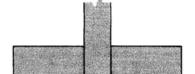
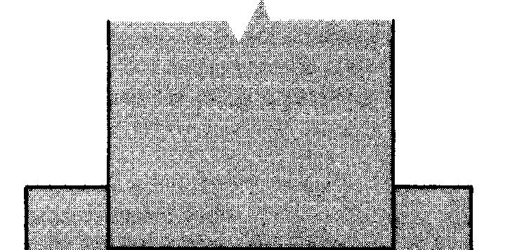
11 Nail yielding at one point. The yield load F u for mode 1.3 (table 1) can be derived using the virtual displacement method. Consider the deformed nail in figure 3. The yield load and failure mode for the nailed joint shown in figure 3 depends on the relative thicknesses and relative embedding strengths of the members. When both members have equal embedding strength f e the work done by nail embedding and nail yield is: where f e = embedding strength for both wood members (load per unit length) (lb/in)(see fig. 2) M y = yield moment of the nail (lb in) (see fig. 2) W = work done by joint (lb in) = integration variables for area of wood experiencing = angular rotation of yielded nail Using small angle approximation, and considering the one yield-point of mode 1.3 where =x 1 + (t 1 x) = thickness of side member (in) = lengths of nail embedment (in) defined by figure 3 = shaded area in figure 3 representing embedment of nail (in 2 ) Substituting Figure 3. Geometry of deformed nail in a two-member joint having one-point nail yield and wood crushing (mode 1.3, table 1). (ML ) and equating external work to internal work where F 1 = lateral force on the nail undergoing unit displacement. Setting the areas equal for the embedment stress yields Let 9
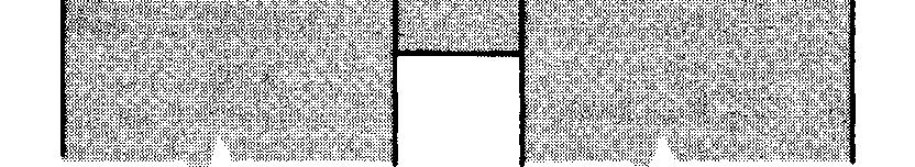
12 Substituting for γ and for results in a = x 1 + (t 1 x) = 2t 1 3x Three-Member Joints Four basic failure modes exist for three-member joints (tables 3, 4, and 6): 1. Wood yield (slotting) in both side members (mode 2.1). 2. Wood yield (slotting) in the main member (mode 2.2). which, for df/dx = 0 gives (It can be shown that 3x 2t 1 < 0, therefore + sign has no interest.) Since > 0 the formula gives a minimum value The thickness requirements can be derived that assure that failure mode 1.3 (table 1) shall occur. (1) No slotting (mode 1.1) in the t l member gives (2) No nail yielding in the t l member gives (3) Nail yielding in the t 2 member gives (2) 3. Wood yield and two-point nail yield (modes 2.3 and 2.3S). 4. Wood yield and four-point nail yield (modes 2.4 and 2.4S). When the wood main member of mode 2.2 is replaced with a steel plate, two additional failure modes are possible (table 4): 5. Wood yield and one-point nail yield (mode 2.2SA). 6. Wood yield and three-point nail yield (mode 2.2SB). The failure modes for wood joints having three wood members are shown in tables 3 and 6. Corresponding modes for joints having either steel side plates or a steel center member are shown in table 4. AU-wooden members. The modes of failure for three-member joints (table 3) ate identical to those for two-member joints with the one exception of failure mode 2.2. For this case the yield load is proportional to the central member thickness. The yield load formulas for three-member wood joints and corresponding thicknesses required to assure that a failure mode shall occur are shown in table 3. They are derived in a manner similar to that used for two-member joints. Steel side or center member. The yield load formulas and corresponding required thicknesses for three-member joints with either steel side or steel center member are shown in table 4. Wood Members With Different Embedding Strengths where α =t 2 /t 1 (fig. 3). Other failure modes. The yield loads for modes of failure 1.1, 1.2, and 1.4 were derived in a similar way. The yield loads and the corresponding thickness requirements assuring the particular failure shall occur are given in table 1. Steel side member. By substituting one wood member in the joint by a steel plate, the formulas given in table 2 can be derived for failure modes 1.2S, 1.3S, and 1.4S. In this case, the steel plate thickness is assumed negligible compared to the wood thickness and the nail length. The load-bearing capacity of a bolt, dowel, or screw joint depends on the angle between the load and the wood s grain. For nailed joints, the effect of grain angle is rather small and it is usually neglected. However, joints made from different species of wood might require different embedment strengths for the wood members similar to different embedment strengths for different angle-to-grain loads. For such cases, the introduction of different f e values for each wood member is useful. Two-Member Joints Two additional failure modes are necessary to describe joints having unequal embedment strength (table 5): 1. Wood yield (slotting) in main member only (mode 1.1A). 2. Wood yield and one-point nail yield in side member only (mode l.3a) 10
13 First we consider the general case of two wood members having embedment strength related by β (fig. 4): Substituting where f e = embedment strength of wood members (lb/in). The yield load for one-point nail yield (mode 1.3) can be derived using virtual displacements. results in (Symbols are defined under equation (l).) which, for df/dx = 0 gives Substituting (+ sign is of no interest) and and equating external work to internal work (3) where F = lateral force on the nail (1 b). Again, the thickness requirements that assure failure mode 1.3 shall occur can be derived. (1) No slotting in the t 1 member gives (2) No nail yielding in the t l member gives Member thickness 2 f e x < M y Embedding strength Figure 4. Two- and three-member joints with unequal embedding strengths. Embedding strength (β f e ) of the main member (t 2 ) is a function of the embedding strength (f e ) of the side member. (ML ) The yield loads for other possible failure modes are derived in a similar way. The ultimate load formulas and the corresponding thickness requirements are given in table 5. Three-Member Joints In the three-member joints, only the modes of failure 2.2, 2.3, and 2.4 (table 6) are of interest. Different relative wood embedding strengths do not change the conditions for failure mode 2.1. Modes 2.3 and 2.4 are identical to modes 1.3 and 1.4 (table 1) in the two-member joint. The yield load formulas and corresponding thicknesses are given in table 6. 11
 Thickness conditions 2.2 0 2.3 2 2.")
14 Table 6. Formulas and failure modes for three-member wood joints. Wood members (t l and t 2 ) have unequal embedding strengths (f e and βf e lb/in respectively). Thickness conditions determine the failure mode Mode of failure number Failure geometry Number of nail yield points Yield load F u (lb) Thickness conditions f e = wood embedding strength (lb/in) M y = nail yield moment (lb in) α = t 2 /t 1 γ = M y /f e 12
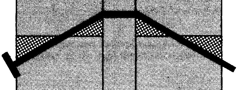
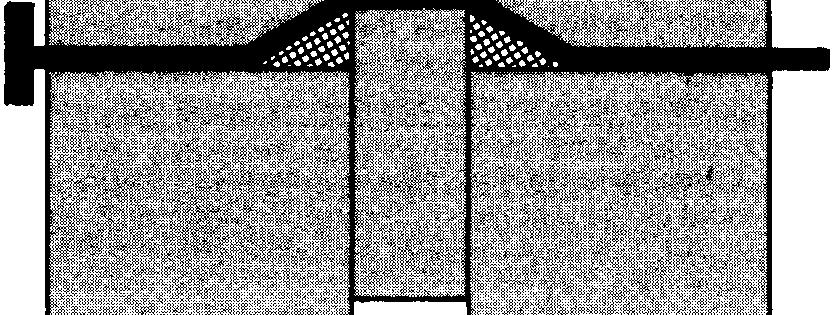
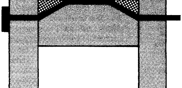
15 Sheathing and Insulation Members Insulation material used between sheathing and wood members has negligible resistance to nail slotting. Insulation does have significant stiffness, however, to keep the distance between sheathing and the other joint member constant, and acts as a gap between joint members. Four failure modes are theoretically possible for joints consisting of a wood main member, a layer of insulation, and an outer sheathing member (table 7): which, for df/dx = 0 gives According to figure 3, yielding of the nail in the main member (t 2 member) requires: (4) 1. Thin sheathing: Wood yield and one-point nail yield in main members only (mode 3.3A). 2. Thin sheathing: Wood yield and two-point nail yield (mode 3.4A). The minimum length of the nail should be approximately: 3. Thick sheathing: Wood yield and one-point nail yield in main members only (mode 3.3B). 4. Thick sheathing: Wood yield and two-point nail yield (mode 3.4B). The yield load, F u, for failure mode 3.3A (table 7) can be derived using the virtual displacement method. Consider the deformed nail in figure 5a: Failure mode 3.4A (table 7) may occur if a bushing or hardboard cleat (fig. 5b) is used under the nailhead, inducing a second yield-point in the nail. Thicker sheathing may also induce a second yield-point in the nail. Table 7 shows loads and corresponding requirements concerning nail length and sheathing thickness for failure modes 3.3A, 3.3B, 3.4A, and 3.4B. Although the sheathing may have an embedding strength different from the wood member, the major contributions to the yield load are nail bending and main member embedment. The error introduced by assuming equal embedment in the members is insignificant for this situation. where a = e + x and e = insulation thickness (in). (Other symbols are defined under equation (l).) Substituting a=e+x and equating external and internal work, where F = lateral force on the nail (1b) Substituting results in 13
16 Table 7. Formulas and failure modes for two-member sheathing to wood joints with an intermediate layer of insulation (e). Wood has embedding strength f e. Thickness conditions and theoretical nail length determine the failure mode Mode of failure number Failure geometry Number of nail yield points Yield load F u (lb) Failure mode determinants Theoretical length of nail: 3.3A 1 Theoretical length of nail: 3.4A 2 Thickness conditions: 3.3B 1 Theoretical length of nail: Thickness conditions: 3.4B 2 Theoretical length of nail: a e = thickness of cleat under nailhead (in) = thickness of intermediate layer of insulation (in) f e = wood embedding strength (lb/in) M y = nail yield moment (lb in) γ = M y /f e 14
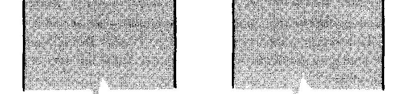
17 Embedding Stress-Deflection Relationship The assumption of plastic behavior of materials in the embedding stress-deformation relationship has proved adequate for the yield model even though the wood behavior does not fit the assumed straight line. However, the yield model is not limited to this assumption. By substituting a fourth-root curve for the assumed plastic embedment behavior we are able to expand the yield model to include joint deformation. Aune (1966) combined the general yield theory and the fourth-root curve relationship between embedding stress and deflection. We derive the ultimate load for a three.-member joint with a steel center member, failure mode 2.2SB (table 4), using the fourth-root curve and symbols defined in figure 6. Figure 5. (a) Geometry of deformed nail with an intermediate layer of insulation of thickness e. Yield load is a function of e. (b) Nailhead fixity results in an additional nail yield-point. (ML ) Using virtual work where f e = embedding stress = f 1, η 1 = corresponding embedding stress and deformation in fourth-root relationship (lb/in, in) M y = yield moment of nail (lb in) x = length of wood embedment (in) δ = joint deflection (in) ξ,η = integration variables for area of wood experiencing fastener embedment (in, in) a. Deformation Substituting b. Rearranging Figure 6. (a) The relationship between wood embedding stress and deformation assumed to be a fourth-root curve. (b) Geometry of deformation for a three-member joint with a steel center member (failure mode 2.2SB, table 4) which we use to exemplify the fourth-root embedment relationship in the yield theory. (ML ) 15
18 Discussion Now, substituting which, for df/dx = 0 gives Similar formulas can be derived for all modes of failure in which the nail forms plastic hinges. For other cases such as failure modes 1.2, 1.3, and 2.3 (tables 1 and 3) the ultimate load can be obtained by successive approximation (Aune 1966). The yield load formulas for two joint configurations are shown in table 8. For comparison the corresponding loads F u are shown for the general case (tables 3 and 4) with η λ = δ. It is not possible to derive formulas for required wood thickness with the fourth-root embedding stress assumption. Table 8. Formulas and failure modes for three-member joints with steel and wood members, comparing estimates of yield loads assuming a plastic relationship (F u ) or assuming a fourth-root curve (F uo ) between wood embedding stress and deformation Mode of failure number Number of nail yield points 2.2SB Estimates of yield load f 1 = wood embedding stress at deformation η 1 f e = wood embedding strength (lb/in) M y = nail yield moment (lb in) F u = yield load of joint assuming plastic wood embedment (lb) F uo = yield load of joint assuming fourth-root wood embedment (lb) δ η = joint deformation (in) = wood embedding deformation (in) (5) Ratio η 1 = wood embedding deformation corresponding to embedding stress f l (in) Comparing formulas for different failure modes leads us to the following observations on the influence of different joint variables. Member Thickness Formulas for required member thickness can provide joint geometries which produce the highest yield load. Yield loads are a function of member thicknesses (t 1 and t 2 ) and the ratio of nail yield moment to wood embedment strength (γ). From the two-member joint formulas in table 1 (wood-to-wood joints), the highest yield load value occurs from two-point nail yield (failure mode 1.4); i.e., t 1 (and t 2 ) has to have a value at least A further increase in the member thickness has no effect on yield load. An identical yield load value is obtained in a steel plate joint by one-point nail yield (mode of failure 1.3S, table 2). In this case the connection between the plate and the nail is regarded as a hinge. The required minimum wood member thickness is the same in both cases. Interestingly, joints of the 1.2S and 1.2 modes of failure (tables 1 and 2) have the same yield load when both members have the same thickness (α = 1) in mode 1.2. When a = 1, modes 1.3S and 1.4 have the same yield load which is times the yield load of mode 1.4S. Nailhead Fixity To show the effect of fixity in the nailhead we compare the yield loads of two-member joints with steel side plates (modes of failure 1.3S and 1.4S, table 2). The theoretical load increases 41 percent when a second yield point occurs in the nail at the steel side plate (mode 1.4S). This increase is attained with just 17 percent increase in wood thickness. This effect may occur in nailed connections where thick steel plates restrain rotation of the nailhead. Steel Side Plates By replacing the wooden side members by steel plates, two- and four-point nail yield in three-member joints (in failures modes 2.3S and 2.4S table 4) correspond to the previously mentioned one- and two-point nail yield in the two-member joints (in failure modes 1.3S and 1.4S, table 2). The yield loads in the three-member joints are double the yield loads in the two-member joints, but the required thicknesses are not doubled. Concerning the three-member joint with steel center member (failure mode 2.2SA, table 4), the yield load always exceeds the highest yield load value for any three-member joint with all-wooden members (i.e., failure mode 2.4). The yield load value derived for the three-member joint with a steel center member and three-point nail yield (failure mode 2.2SB) is identical with that for three-member joint with steel side plates and four-point nail yield (failure mode 2.4S). This yield load value turns out to be 41 percent higher than the corresponding value in an all-wooden three-member joint. This advantage is realized in a combined nail/steel plate joint where one or several plates are placed in slots within wooden truss members. The higher yield load is obtainable only with an adequate distance between the slots or the plates. 16
19 Insulation Layer From the formulas given in table 7, it is not possible to see the effect on the yield load either of the thickness of insulation, e, or of the mode of failure. These effects, however, can be analyzed by assuming certain ratios between insulation thickness, e, and the square root of the ratio of nail yield to wood embedment, The yield load is greatly decreased by having an intermediate layer of insulation instead of a plain connection. The trend is the same for all three modes of failure (fig. 7). Failure mode 3.4A gives the highest yield load, which is 40 to 90 percent higher than the corresponding load with failure mode 3.3A and 5 to 40 percent higher than the load with failure mode 3.4B (see fig. 7). This effect needs to be. taken into account in designing nailed joints that have a layer of insulation. Different Embedding Strengths To demonstrate the influence of different embedding strengths in a joint, we compare the formulas in table 5 with the corresponding formulas in the general case (tables 1-4). The complexity of some of the formulas makes it difficult to compare the whole range of failure modes. Table 9 shows the comparison between a two-member joint with two-point nail yield (failure mode 1.4, the maximum obtainable ultimate load) and a two-member joint with no nail yield, only crushing in both wood members (failure mode 1.2). The analysis assumes member thicknesses are equal. The formula for failure mode 1.4 shows that yield loads are not very sensitive to increases in embedding strength of one joint member. This may be seen by comparing yield loads of joints with different ratios of main-member to side-member embedding strengths (β). The yield load increases 9 percent for β = 1.5 and 15 percent for β = 2.0. Möller (1950) suggests using an average embedding strength value when calculating the yield load of joints with unequal embedding strengths. Doing so leads to a marked reduction in the required thickness of the member having the highest embedding strength (t 2 ). Required thickness is reduced to 78 percent for β = 1.5 and to 65 percent for β = 2.0. Failure mode 1.4 occurs in a thinner member that has a higher embedding strength. Assuming failure mode 1.2 occurs in a joint and that member thicknesses are equal, table 9 gives some indication of the effect of increasing the embedding strength of one member. In this case, in contrast to the case previously discussed, the yield load depends entirely on the embedding strength. For this reason, it is logical to expect a relatively larger increase in the ultimate load by the 1.2 mode of failure than by the 1.4 mode when different embedding strengths are considered. Changing member thickness would make little change in results. Figure 7. A dimensionless form of the Field load is used to compare the effect of increased insulation thickness Mode 3.4A (hardboard cleat under the nailhead) gives the highest yield load throughout the range on insulation thicknesses. (ML ) Table 9. Comparison between two-member joint with two-point nail yield (failure mode 1.4) and a two-member joint with no nail yield (failure mode 1.2) for wood members with unequal embedding strengths Mode of Increase in Change in required member thickness failure β maximum load number t 1 t
20 Summary Fourth-Root Curve Comparing the ratio of yield loads demonstrates the effect of using a fourth-root curve in place of the plastic embedding relationship (table 8). The fourth-root curve method gives a yield load 6 percent lower than that obtained in the general case assuming plasticity under embedding stress behavior. The reduction caused by changing the assumed distribution of embedding strength is less than expected. It is not possible to derive formulas for the required wood thickness using this fourth-root curve method. Comparisons with the general case discussed above, however, will give some indication of required wood thickness. The distance x between the abutting surfaces and the yield point in the nail appears to be approximately 6 percent higher using the general case than by the fourth-root curve method. A total increase of 6 percent in the required wood thickness seems therefore to be a reasonable prediction for the modes of failure given in table 8. Deviations of that order might well be ignored. By using the fourth-root curve method, it should be possible to predict a load-deflection curve for the entire joint. In addition to assumptions about the embedding stress distribution, we make a fundamental assumption about the nail s moment-rotation curve. The nail is generally assumed to be plastic, as shown in figure 2. This assumption is correct except for the initial part of the moment-rotation curve. In fact, the predicted curve should be corrected from the origin to a point where the bending moment of the nail approaches M,. Aune (1966) has shown how to correct the predicted curve by using a method of successive approximation. The moment-rotation curve for the nail bending should therefore be recorded during testing. The European-based yield theory provides yield load formulas for two- and three-member nailed wood joints. Additional yield theory formulas address joints with steel plate members, unequal wood embedding strength, and a gap made by an insulation layer. Final formulas include a fourth-root wood embedding stress-deformation relationship. If we control the relative member thicknesses, we can theoretically control the yield mode. Certain yield modes have more nail yield points which increase a joint s theoretical ultimate lateral load. In many cases steel plate members theoretically increase the ultimate lateral load over all-wood member joints. The increase in yield load is partially due to additional nail yield points. Additional nail yield points when steel side plates are used account for increased load caused by nailhead fixity. An intermediate layer of insulation theoretically reduces the yield load depending on the thickness of the insulation. In terms of the yield theory, we can account for increased embedding strength in one wood member of a two-member joint whenever wood crushing rather than nail yield is the predominant failure mode. Use of a fourth-root embedding curve has little effect on the theoretical ultimate lateral load. The fourth-root curve, however, might make it possible to predict load-deformation behavior of a nailed joint near the yield point. Experimental verification of the yield theory developed in this report has been provided by the authors in a companion research report (Aune and Patton-Mallory 1986).
21 Literature Cited American Society for Testing and Materials. Standard methods of testing mechanical fasteners in wood. ASTM D In: Annual book of standards, Part 22. Philadelphia, PA: ASTM; Aune, P. Tradstiftforbindelsers bäreevne. Beregning og forsök: The load carrying capacity of nailed joints. Calculations and experiments (in Norwegian with English summary). Trondheim, Norway: Norges Tekniske Högskole (The Norwegian Institute of Technology); Aune, P.; Patton-Mallory, M.Lateral load-bearing capacity of nailed joints based on the yield theory: Experimental verification. Res. Pap. FPL 470. Madison, WI: U.S. Department of Agriculture, Forest Service, Forest Products Laboratory; CIB. Structural timber design code. 6th ed. International Council for Building Research Studies and Documentation, Working Group W18 Timber Structures; Ehlbeck, J. Nailed joints in wood structures. No Blacksburg, VA: Virginia Polytechnic Institute and State University, Wood Research and Wood Construction Laboratory; Forest Products Laboratory. Wood handbook: Wood as an engineering material. Agric. Handb. 72. Washington, DC: U.S. Department of Agriculture, Forest Service; rev p. Johansen, K. W. Forsög med Träforbindelser. Danmarks Tekniske Höjskole Medd. No. 10 (in Danish). Copenhagen: Laboratoriet for bygningsteknik; Johansen, K. W. Theory of timber connections. Publ. 9. Bern: International Association of Bridge and Structural Engineering; Larsen, H. J. K. W. Johansen s nail tests. Bygningsstatiske Meddelelser. 48: 9-30; Larsen, H. J. The yield load of bolted and nailed joints. In: Proceedings, International Union of Forestry Research Organizations working group on structural utilization; 1973 September/October. Pretoria, Republic of South Africa; [n.d.]. Larsen, H. J. Design of bolted joints. Bordeaux, France: International Council for Building Research Studies and Documentation, Working Commission W 18 Timber Structures; October Larsen, H. J.; Reestrup, V. Tests on screws in wood. Bygningsstatiske Meddelelser. 1: 3-36; Mack, J. J. The strength of nailed timber joints. Tech. Pap. No. 9. Melbourne, Australia: CSIRO Division of Forest Products; McLain, T. E.; Thangjitham, S. Bolted wood-joint yield model. Journal of Structural Engineering, American Society of Civil Engineers. 109(8): ; Meyer, A. Die Tragfähigkeit von Nagelverbindungen bei Statischer Belastung: The bearing strength of nailed joints under load. Holz als Roh- und Werkstoff. 15(2): ; Möller, T. En ny metod för beräkning av spikförband: New method of estimating the bearing strength of nailed wood connections (in Swedish and English translation). Rep. No Gothenburg, Sweden: Chalmers Tekniska Högskolas Handlingar; Nordtest. Nails in wood. Bending strength. NT Build 136. Stockholm, Sweden: Nordtest, Box 5103, S ; Nordtest. Nails in wood. Embedding strength. NT Build 135. Stockholm, Sweden: Nordtest, Box 5103, S ; Nordtest. Nails in wood. Lateral strength. NT Build 133. Stockholm, Sweden: Nordtest, Box 5103, S ; Nordtest. Nails in wood. Withdrawal strength. NT Build 134. Stockholm, Sweden: Nordtest, Box 5103, S ; Norén, B. Formler för hallfasthet hos mekaniska träförband (in Swedish). Formulas indicating the strength of mechanical wood joints. Medd. Series B, No Stockholm: Svenska Träforskningsinstitutet; Siimes, F. E.; Johanson, P. E.; Niskanen, E. Investigations on the ultimate embedding stress and nail holding power of finish pine. Tiedoitus 122. Helsinki: The State Institute for Technical Research; Wilson, T.R.C. Tests made to determine lateral resistance of wire nails. Engineering Records. 75: ;
22 Additional Literature List of Symbols Antonides, C. E.; Vanderbilt, M. D.; Goodman, J. R. Interlayer gap effect on nailed joint stiffness. Wood Science. 13(1): 41-46; Ehlbeck, J. Load-carrying capacity and deformation characteristics of nailed joints. Bordeaux, France: International Council for Building Research Studies and Documentation, Working Commission W18 Timber Structures; October Ehlbeck, J.; Larsen, H. J. Load-slip relationship of nailed joints. Warsaw, Poland: International Council for Building Research Studies and Documentation, Working Commission W 18 Timber Structures; May Foschi, R. O. Load-slip characteristics of nails. Wood Science. 7(1): 69-74; Foschi, R. O.; Bonac, T. Load-slip characteristics for connections with common nails. Wood Science. 9(3): ; Jenkins, J. L.; Polensek, A.; Bastendorff, K. M. Stiffness of nailed wall joints under short and long term lateral loads. Wood Science. 11(3): ; Larsen, H. J.; Riberholt, H. Load-carrying capacity of laterally loaded nails and brads in particle boards and wood fibre boards. Rep. No Aalborg, Denmark: Aalborg University Center; Mack, J. J. The load-displacement curve for nailed joints. Journal of the Institute of Wood Science. 7(6): 34-36; McLain, T. E. Curvilinear load-slip relations in laterally loaded nailed joints. Proc. P Madison, WI: Forest Products Research Society; Mascarenhas, A.C.Q. Load transmission by nails in particleboard. Proc. P Madison, WI: Forest Products Research Society; Möhler, K.; Budianto, T.; Ehlbeck, J. Embedding resistance and load-displacement characteristics of particleboard loaded with cylindrical fasteners. Proc. P Madison, WI: Forest Products Research Society; Möhler, K.; Budianto, T.; Ehlbeck J. Testing methods for joints with mechanical fasteners in load-bearing timber structures. Final recommendations. Matériaux et Constructions, Paris: Joint Committee RILEM/CIB-3TT; 12(70). Norén, B. Nailed joints-their strength and rigidity under short-term and long-term loading. Rep. 22. Stockholm: The National Swedish Institute for Building Research, Box , ; Patterson, D. W. Nailed joints under lateral load need additional research. Proc. P Madison, WI: Forest Products Research Society; Scholten, J. A. Nail-holding properties of southern hardwoods. Tech. Article Madison, WI: US. Department of Agriculture, Forest Service, Forest Products Laboratory; Scholten, J. A. Strength of wood joints made with nails. Res. Note FPL Madison, WI: U.S. Department of Agriculture, Forest Service; Wilkinson, T. L. Theoretical lateral resistance of nailed joints. Proc. Pap Journal of the Structural Division, American Society of Civil Engineers. 97(ST5): ; Wilkinson, T. L. Analyses of nailed joints with dissimilar members. Proc. Pap Journal of the Structural Division, American Society of Civil Engineers. 98(ST9): ; a, x, x 1 = distance along the nail embedding the wood (in) e = insulation thickness, gap (in) f 1 = wood embedding stress at deformation η 1 (lb/in) f e = wood embedding strength (lb/in) f y = yield strength of the nail (lb/in*) F = lateral force on nail (lb) F u = computed ultimate load, yield load (lb) = nail length (in) M y = yielding moment of the nail (lb in) t l,t 2 = wood member thickness (in) W = work done by joint (lb in) α =t 2 /t l, ratio of main member thickness to side member thickness β = ratio of joint embedding strengths δ = joint deformation (in) η, η 1 = wood embedding deformation (in) θ = angle θ 1 = angular deflection ξ = coordinate for integration Acknowledgment The senior author was supported by the Norwegian Institute of Technology at the University of Trondheim and the Norwegian Council for Scientific and Industrial Research. The research was performed at the Forest Products Laboratory, Forest Service, U.S. Department of Agriculture /86 20 U.S. GOVERNMENT PRINTING OFFICE:1986/ /20028
Lateral Load-Bearing Capacity of Nailed Joints Based on the Yield Theory
 United States Department of Agriculture Forest Service Forest Products Laboratory Research Paper FPL 470 Lateral Load-Bearing Capacity of Nailed Joints Based on the Yield Theory Experimental Verification
Lawrence A. Soltis, M. and Robert J. Ross, M. 1
 REPAIR OF WHITE OAK GLUED-LAMINATED BEAMS Lawrence A. Soltis, M. and Robert J. Ross, M. 1 Abstract Connections between steel side plates and white oak glued-laminated beams subjected to tension perpendicular-to-grain
B.L. Wills D.A. Bender S.G. Winistorfer 1
 CONTEMPORARY ISSUES FACING NAIL FASTENERS B.L. Wills D.A. Bender S.G. Winistorfer 1 INTRODUCTION Nails have been used for hundreds of years for a variety of purposes, but it was not until the 19 th century
Lawrence A. Soltis. James K. Little
 ANGLE TO GRAIN STRENGTH OF DOWEL-TYPE FASTENERS Lawrence A. Soltis Supervisory Research Engineer Forest Products Laboratory,' Forest Service U.S. Department of Agriculture, Madison, WI 53705 Suparman Karnasudirdja
LOAD CARRYING CAPACITY OF METAL DOWEL TYPE CONNECTIONS OF TIMBER STRUCTURES
 Vol. 10, Issue /014, 51-60 DOI: 10.478/cee-014-0011 LOAD CARRYING CAPACITY OF METAL DOWEL TYPE CONNECTIONS OF TIMBER STRUCTURES Jozef GOCÁL 1,* 1 Department of Structures and Bridges, Faculty of Civil
WITHDRAWAL AND LATERAL STRENGTH OF THREADED NAILS
 238 WITHDRAWAL AND LATERAL STRENGTH OF THREADED NAILS Douglas R. Rammer, Donald A. Bender, and David G. Pollock An experimental study on the performance of threaded nails was conducted to understand and
Simplified analysis of timber rivet connections
 Simplified analysis of timber rivet connections Stahl, Douglas C., 1 Begel, Marshall, 2 and Wolfe, Ronald W. 3 ABSTRACT Timber rivets, fasteners for glulam and heavy timber construction, have been used
SIMPLIFIED DESIGN PROCEDURE FOR GLUED-LAMINATED BRIDGE DECKS
 ABSTRACT Procedures have recently been developed for the design of glued-laminated bridge decks and for steel dowel connectors. However, since most bridges are designed in accordance with the Specifications
DESIGN EQUATION FOR MULTIPLE- FASTENER WOOD CONNECTIONS
 DESIGN EQUATION FOR MULTIPLE- FASTENER WOOD CONNECTIONS By John J. Zahn, 1 Member, ASCE ABSTRACT: A compared design equation is presented for the design of multiple fastener connections of wood members.
SCREWS WITH CONTINUOUS THREADS IN TIMBER CONNECTIONS
 SCREWS WITH CONTINUOUS THREADS IN TIMBER CONNECTIONS Prof. Dr.-Ing. H. J. Blaß, Dipl.-Ing. I. Bejtka Universität Karlsruhe (TH), Germany Abstract Screws, bolts and dowels loaded perpendicular to the fastener
The predictive model for strength of inclined screws as shear connection in timber-concrete composite floor
 The predictive model for strength of inclined screws as shear connection in timber-concrete composite floor F. Moshiri, C. Gerber, H.R. Valipour, R. Shrestha & K.I. Crews Centre for built infrastructure,
Nails are among the most common fasteners used
 THREADED-NAIL FASTENERS RESEARCH AND STANDARDIZATION NEEDS B. L. Wills, S. G. Winistorfer, D. A. Bender, D. G. Pollock ABSTRACT. Threaded nail fasteners are commonly used in agricultural and commercial
TEST SERIES TO EVALUATE THE STRUCTURAL BEHAVIOUR OF ISOBOARD OVER RAFTER SYSTEM
 TEST SERIES TO EVALUATE THE STRUCTURAL BEHAVIOUR OF ISOBOARD OVER RAFTER SYSTEM J A Wium Institute of Structural Engineering 19 November 2007 ISI2007-3 TEST SERIES TO EVALUATE THE STRUCTURAL BEHAVIOUR
LRFD FOR ENGINEERED WOOD STRUCTURES- CONNECTION BEHAVIORAL EQUATIONS
 LRFD FOR ENGINEERED WOOD STRUCTURES- CONNECTION BEHAVIORAL EQUATIONS By Thomas E. McLain, 1 Lawrence A. Soltis. 2 David G. Pollock Jr., 3 Members, ASCE, and Thomas L. Wilkinson 4 ABSTRACT: A new design
PERFORMANCE OF FASTENERS IN WOOD
 COMPOSITES AND MANUFACTURED PRODUCTS PERFORMANCE OF FASTENERS IN WOOD FLOUR-THERMOPLASTIC COMPOSITE PANELS ROBERT H. FALK* DANIEL J. Vos STEVEN M. CRAMER* BRENT W. ENGLISH ABSTRACT In the building community,
Timber Bridge Hardwood Glulam Deck Connector Evaluations under Static and Repetitive Loads
 Timber Bridge Hardwood Glulam Deck Connector Evaluations under Static and Repetitive Loads John J. Janowiak, Harvey B. Manbeck, Daniel G. Thomforde, and Ray W. Witmer, Penn State University Abstract Timber
LRFD for Engineered Wood Structures - Connection Behavioral Equations
 Digital Commons @ George Fox University Faculty Publications - Department of Mechanical and Civil Engineering Department of Mechanical and Civil Engineering 1993 LRFD for Engineered Wood Structures - Connection
SCREW WITHDRAWAL RESISTANCE SHEET METAL SCREWS IN PARTICLEBOARD AND MEDIUM-DENSITY HARDBOARD
 SCREW WITHDRAWAL RESISTANCE OF TYPES A AND AB SHEET METAL SCREWS IN PARTICLEBOARD AND MEDIUM-DENSITY HARDBOARD U.S.D.A. FOREST SERVICE RESEARCH PAPER FPL 239 1974 U.S. DEPARTMENT OF AGRICULTURE FOREST
Connection Design Examples
 Connection Design Examples Using the 2015 NDS (DES345) Lori Koch, P.E. Manager, Educational Outreach American Wood Council Adam Robertson, M.A.Sc., P.Eng. Manager, Codes and Standards Canadian Wood Council
Development of Limit States Design Method for Joints with Dowel Type Fasteners Part 3: Basis of European Yield Model Design Procedure
 Manufacturing & Products Development of Limit States Design Method for Joints with Dowel Type Fasteners Part 3: Basis of European Yield Model Design Procedure Project No. PN2.198 (Part 3) 24 Forest & Wood
Bolts and Set Screws Are they interchangeable?
 1903191HA Bolts and Set Screws Are they interchangeable? Prof. Saman Fernando Centre for Sustainable Infrastructure SUT Introduction: This technical note discusses the definitions, standards and variations
Analysis and Testing of a Ready-to-Assemble Wood Framing System
 Analysis and Testing of a Ready-to-Assemble Wood Framing System by Vladimir G. Kochkin Thesis submitted to the Faculty of the Virginia Polytechnic Institute and State University in partial fulfillment
RlGIDITY AND STRENGTH OF WALL FRAMES BRACED WlTH METAL STRAPPING
 RlGIDITY AND STRENGTH OF WALL FRAMES BRACED WlTH METAL STRAPPING information Reviewed and Reaffirmed March 1955 No. R1603 UNITED STATES DEPARTMENT OF AGRICULTURE FOREST SERVICE FOREST PRODUCTS LABORATORY
STRUCTURAL TIMBER DESIGN
 STRUCTURAL TIMBER DESIGN to Eurocode 5 2nd Edition Jack Porteous BSc, MSc, DIC, PhD, CEng, MIStructE, FICE Director lack Porteous Consultancy and Abdy Kernlani BSc, MSc, PhD, CEng, FIStructE, FIWSc Professor
Changes in the 2001 NDS for Wood Construction
 Changes in the 2001 NDS for Wood Construction Philip Line, P.E.; Dr. Robert Taylor, P.Eng.; John Buddy Showalter, P.E.; Bradford K. Douglas, P.E. Introduction The 2001 Edition of the National Design Specification
Splitting strength of beams loaded perpendicular to grain by connections, a fracture mechanical approach
 Splitting strength of beams loaded perpendicular to grain by connections, a fracture mechanical approach Ad Leijten Civil Eng. PhD, Senior Researcr University of Techn. Delft Delft, T Netrlands A.Leijten@citg.tudelft.nl
CHARACTERISTICS OF LUMBER-TO-LUMBER FRAMING CONNECTIONS IN LIGHT-FRAME WOOD STRUCTURES
 CHARACTERISTICS OF LUMBER-TO-LUMBER FRAMING CONNECTIONS IN LIGHT-FRAME WOOD STRUCTURES Andi Asiz 1*, Lina Zhou 1, Ying Hei Chui 1 ABSTRACT: Connections are arguably the most important part of light-frame
Comparison of behaviour of laterally loaded round and squared timber bolted joints
 Focussed on Modelling in Mechanics Comparison of behaviour of laterally loaded round and squared timber bolted joints Antonín Lokaj, Kristýna Klajmonová VŠB echnical University of Ostrava, Faculty of Civil
Moment-Resisting Connections In Laminated Veneer Lumber (LVL) Frames
 Frames") Moment-Resisting Connections In Laminated Veneer Lumber (LVL) Frames Andy van Houtte Product Engineer-LVL Nelson Pine Industries Nelson, NZ Andy Buchanan Professor of Civil Engineering Peter Moss Associate
Moment-Resisting Connections In Laminated Veneer Lumber (LVL) Frames Andy van Houtte Product Engineer-LVL Nelson Pine Industries Nelson, NZ Andy Buchanan Professor of Civil Engineering Peter Moss Associate
Load carrying capacity of dowelled connections
 Load carrying capacity of dowelled connections H.J. Blass, Karlsruhe Institute of Technology F. Colling, Augsburg University of Applied Sciences Keywords: Dowel, yield moment, connection 1 Introduction
1/2/2016. Lecture Slides. Screws, Fasteners, and the Design of Nonpermanent Joints. Reasons for Non-permanent Fasteners
 Lecture Slides Screws, Fasteners, and the Design of Nonpermanent Joints Reasons for Non-permanent Fasteners Field assembly Disassembly Maintenance Adjustment 1 Introduction There are two distinct uses
2002 ADDENDUM to the 1997 NDS and PRIOR EDITIONS
 AMERICAN FOREST & PAPER ASSOCIATION American Wood Council Engineered and Traditional Wood Products March 2002 2002 ADDENDUM to the 1997 NDS and PRIOR EDITIONS The 2001 Edition of the National Design Specification
What happens to bolt tension in large joints?, Fasteners, Vol. 20, No. 3, 1965, Publication No. 286
 Lehigh University Lehigh Preserve Fritz Laboratory Reports Civil and Environmental Engineering 1965 What happens to bolt tension in large joints?, Fasteners, Vol. 20, No. 3, 1965, Publication No. 286 G.
Glued laminated timber beams repair.
 Glued laminated timber beams repair. Master s Degree Extended Abstract Ricardo Cardoso Henriques da Silva Keywords: glulam, delamination, self-tapping screw, plywood, repair November 2014 1. INTRODUCTION
Connection Solutions for Wood-frame Structures. Copyright Materials. Learning Objectives
 Connection Solutions for Wood-frame Structures Presented by: John Buddy Showalter, P.E. Vice President, Technology Transfer The Wood Products Council is a Registered Provider with. Credit(s) earned on
CCFSS Technical Bulletin
 CCFSS Technical Bulletin Vol. 12, No. 1 February 2003 FREQUENTLY ASKED QUESTIONS CONCERNING THE AISI BASE TEST METHOD AND THE USE OF THE AISI ANCHORAGE EQUATIONS Answers Provided by the AISI Task Committee
Comparative Evaluation of Resistance Made Simple Shear Connection with Bolts and With Welding
 International Journal of Engineering Inventions e-issn: 78-7461, p-issn: 319-6491 Volume 3, Issue 7 (February 014) PP: 1-5 Comparative Evaluation of Resistance Made Simple Shear Connection with Bolts and
Engineering Research into Traditional Timber Joints
 Engineering Research into Traditional Timber Joints Richard Harris, Wen- Shao Chang, Peter Walker (BRE CICM, The University of Bath) and Jon Shanks (CSAW Research Fellow, School of Architecture & Design,
ABSTRACT INTRODUCTION
 ISSN impresa 0717-3644 Maderas. Ciencia y tecnología 15(2): 127-140, 2013 ISSN online 0718-221X DOI 10.4067/S0718-221X2013005000011 INVESTIGATION ON LATERAL RESISTANCE OF JOINTS MADE WITH DRYWALL AND SHEET
Ductility of large-scale dowelled CLT connections under monotonic and cyclic loading
 Ductility of large-scale dowelled CLT connections under monotonic and cyclic loading Lisa-Mareike Ottenhaus 1, Minghao Li 2, Tobias Smith 3 1. PhD candidate, Department of Civil and Natural Resources Engineering,
Title. CitationJournal of Wood Science, 58(4): Issue Date Doc URL. Rights. Type. File Information.
: Issue Date Doc URL. Rights. Type. File Information.") Title Effective lateral resistance of timber-plywood-timbe Author(s)Wanyama, Okumu Gordon; Sawata, Kei; Hirai, Takuro; K CitationJournal of Wood Science, 58(4): 315-321 Issue Date 2012-08 Doc URL http://hdl.handle.net/2115/50078
Title Effective lateral resistance of timber-plywood-timbe Author(s)Wanyama, Okumu Gordon; Sawata, Kei; Hirai, Takuro; K CitationJournal of Wood Science, 58(4): 315-321 Issue Date 2012-08 Doc URL http://hdl.handle.net/2115/50078
THE EFFECT OF END DISTANCE AND NUMBER OF READY-TO- ASSEMBLE FURNITURE FASTENERS ON BENDING MOMENT RESISTANCE OF CORNER JOINTS.
 THE EFFECT OF END DISTANCE AND NUMBER OF READY-TO- ASSEMBLE FURNITURE FASTENERS ON BENDING MOMENT RESISTANCE OF CORNER JOINTS Milan Simek{ Research Assistant Department of Furniture, Design and Habitation
Withdrawal Strength of Staples
 Holding Strength of Staples Staples are widely used in the furniture industry, both for upholstering purposes and for frame construction. The staples used for upholstering are usually rather small and
Development of Limit States Design Method for Joints with Dowel Type Fasteners Part 2: Comparison of Experimental Results with European Yield Model
 Manufacturing & Products Project No. PN02.1908 (Part 2) Development of Limit States Design Method for Joints with Dowel Type Fasteners Part 2: Comparison of Experimental Results with European Yield Model
Glulam Connection Details
 T E C H N I C A L N O T E Glulam Connection Details Note: This version is superseded by a more current edition. Check the current edition for updated design and application recommendations. ENGINEERED
Load-carrying capacity of timber frame diaphragms with unidirectional support
 Load-carrying capacity of timber frame diaphragms with unidirectional support Jørgen Munch-Andersen, Danish Timber Information, 2012-06-26 Introduction The rules for determining the load-carrying capacity
STABILITY. SECURITY. INTEGRITY.
 MODEL 150 HELICAL ANCHOR SYSTEM PN #MBHAT STABILITY. SECURITY. INTEGRITY. 150 Helical Anchor System About Foundation Supportworks is a network of the most experienced and knowledgeable foundation repair
INFLUENCE OF PILES ON LOAD- SETTLEMENT BEHAVIOUR OF RAFT FOUNDATION
 INFLUENCE OF PILES ON LOAD- SETTLEMENT BEHAVIOUR OF RAFT FOUNDATION BALESHWAR SINGH Department of Civil Engineering Indian Institute of Technology Guwahati Guwahati 78139, India NINGOMBAM THOIBA SINGH
Dowel connections in laminated strand lumber
 Dowel connections in laminated strand lumber Cranswick, Chad J. 1, M c Gregor, Stuart I. 2 ABSTRACT Laminated strand lumber (LSL) is a relatively new structural composite lumber. As such, very limited
Hanger bolts and solar fasteners in sandwich panels
 Hanger bolts and solar fasteners in sandwich panels Helmut Krüger 1, Thomas Ummenhofer 2, Daniel C. Ruff 3 Abstract For the energetic use of sunlit roofs, photovoltaic and solar thermal elements are mounted
Rigid Connections. Between Wood posts and concrete
 Research + Technology Research + Technology Rigid Connections Between Wood posts and concrete By David R. Bohnhoff, PHD, PE Modeling Connections The primary goal of a structural engineer is to ensure that
THE EFFECT OF THREAD GEOMETRY ON SCREW WITHDRAWAL STRENGTH
 THE EFFECT OF THREAD GEOMETRY ON SCREW WITHDRAWAL STRENGTH Doug Gaunt New Zealand Forest Research Institute, Rotorua, New Zealand ABSTRACT Ultimate withdrawal values for a steel 16mm diameter screw type
Connection and Tension Member Design
 Connection and Tension Member Design Notation: A = area (net = with holes, bearing = in contact, etc...) Ae = effective net area found from the product of the net area An by the shear lag factor U Ab =
Screw Withdrawal A Means to Evaluate Densities of In-situ Wood Members
 Screw Withdrawal A Means to Evaluate Densities of In-situ Wood Members Zhiyong Cai Assistant Professor, Dept. of Forest Science, Texas A&M University, College Station, Texas, USA Michael O. Hunt Professor
The Wood Products Council is a Registered Provider with. . Credit(s) earned on completion of this program will be
 earned on completion of this program will be") Connection Solutions for Wood-frame Structures Presented by: John Buddy Showalter, P.E. Vice President, Technology Transfer The Wood Products Council is a Registered Provider with. Credit(s) earned on
Connection Solutions for Wood-frame Structures Presented by: John Buddy Showalter, P.E. Vice President, Technology Transfer The Wood Products Council is a Registered Provider with. Credit(s) earned on
Investigations on the Effectiveness of Self-tapping Screws in Reinforcing Bolted Timber Connections
 Investigations on the Effectiveness of Self-tapping Screws in Reinforcing Bolted Timber Connections Mohammad Mohammad Group Leader, Building Systems Forintek Canada Corp, Eastern Division Quebec, Canada
4-Bolt Wood-to-Steel Connections
 The Effects of Row Spacing and Bolt Spacing in 6-Bolt and 4-Bolt Wood-to-Steel Connections By Michael A. Dodson This thesis submitted in partial fulfillment of the requirements for the degree of MASTER
Fasteners as Damage Indicators in Timber Structures
 In: Gopu, Vijaya K.A., ed. Proceedings of the international wood engineering conference; 1996 October 28-31; New Orleans LA. Baton Rouge, LA: Louisiana State University: Vol. 4: 38-45 Fasteners as Damage
ASSESSMENT OF BASIC STEEL I-SECTION BEAM BRACING REQUIREMENTS BY TEST SIMULATION
 ASSESSMENT OF BASIC STEEL I-SECTION BEAM BRACING REQUIREMENTS BY TEST SIMULATION A Thesis By Evan P. Prado In Partial Fulfillment Of the Requirements for the Degree Master of Science in Civil Engineering
Structural Strength of Lapped Cold-Formed Steel Z-Shaped Purlin Connections with Vertical Slotted Holes
 Missouri University of Science and Technology Scholars' Mine International Specialty Conference on Cold- Formed Steel Structures (2014) - 22nd International Specialty Conference on Cold-Formed Steel Structures
Mechanical behavior of fiberglass reinforced timber joints
 Mechanical behavior of fiberglass reinforced timber joints Chen, Chi-Jen 1 ABSTRACT The objective of this research is to investigate the mechanical performance of dowel-type timber joints reinforced by
Bolt Material Types and Grades 1- Bolts made of carbon steel and alloy steel: 4.6, 4.8, 5.6, 5.8, 6.8, 8.8, 10.9 Nuts made of carbon steel and alloy
 Bolt Material Types and Grades 1- Bolts made of carbon steel and alloy steel: 4.6, 4.8, 5.6, 5.8, 6.8, 8.8, 10.9 Nuts made of carbon steel and alloy steel: 4, 5, 6, 8, 10, 12 2- Bolts made of stainless
AN INNOVATIVE FEA METHODOLOGY FOR MODELING FASTENERS
 AN INNOVATIVE FEA METHODOLOGY FOR MODELING FASTENERS MacArthur L. Stewart 1 1 Assistant Professor, Mechanical Engineering Technology Department, Eastern Michigan University, MI, USA Abstract Abstract Researchers
AN IMPROVED SHEAR TEST FIXTURE USING THE IOSIPESCU SPECIMEN
 AMD-VOl. 231/MD-VOl. 85 Mechanics of Cellulosic Materials 1999 ASME 1999 ABSTRACT AN IMPROVED SHEAR TEST FIXTURE USING THE IOSIPESCU SPECIMEN Jen Y. Liu, Dwight D. Flach, Robert J. Ross, and Gary J. Lichtenberg
Design of structural connections for precast concrete buildings
 BE2008 Encontro Nacional Betão Estrutural 2008 Guimarães 5, 6, 7 de Novembro de 2008 Design of structural connections for precast concrete buildings Björn Engström 1 ABSTRACT A proper design of structural
Rafter Purlins D7+ FRILO Software GmbH As of 16/01/2019
 Rafter Purlins D7+ FRILO Software GmbH www.frilo.com info@frilo.com As of 16/01/2019 Rafter Purlins - D7+ Contents Application options 3 Basis of calculation 5 Definition of the structural system 6 Basic
TECH SHEET PEM - REF / TESTING CLINCH PERFORMANCE. SUBJECT: Testing clinch performance of self-clinching fasteners.
 PEM - REF / TESTING CLINCH PERFORMANCE SUBJECT: Testing clinch performance of self-clinching fasteners. A self-clinching fastener s performance can be divided into two major types. The first is self-clinching
Dowel type joints Influence of moisture changes and dowel surface smoothness. Erik Serrano and Johan Sjödin, Växjö University, Sweden
 Dowel type joints Influence of moisture changes and dowel surface smoothness Erik Serrano and Johan Sjödin, Växjö University, Sweden Background and introduction With the increased use of glulam in large-span
PRO LIGNO Vol. 11 N pp
 FINITE ELEMENT SIMULATION OF NAILED GLULAM TIMBER JOINTS Mats EKEVAD Luleå University of Technology Division of Wood Science and Engineering SE-931 87 Skellefteå, Sweden Tel: +46 910 585377; E-mail: mats.ekevad@ltu.se
Effect of shoulders on bending moment capacity of round mortise and tenon joints
 Effect of s on bending moment capacity of round mortise and tenon joints Carl Eckelman Yusuf Erdil Eva Haviarova Abstract Tests were conducted to determine the effect of close-fitting s on the bending
ICC-ES Evaluation Report Reissued June 1, 2010 This report is subject to re-examination in one year.
 ICC-ES Evaluation Report ESR-2648 Reissued June 1, 2010 This report is subject to re-examination in one year. www.icc-es.org (800) 423-6587 (562) 699-0543 A Subsidiary of the International Code Council
Prediction of Reinforcement Effect by Screw on Triangular Embedment Perpendicular to the Grain with Variation of Screw Locations
 Open Journal of Civil Engineering,,, 67-73 http://dx.doi.org/.436/ojce..3 Published Online September (http://www.scirp.org/journal/ojce) of Reinforcement Effect by Screw on Triangular Embedment Perpendicular
ENGINEERING FUNDAMENTALS
 SENSORS FOR RESEARCH & DEVELOPMENT WHITE PAPER #20 ENGINEERING FUNDAMENTALS OF THREADED FASTENER DESIGN AND ANALYSIS Written By Ralph S. Shoberg www.pcb.com info@pcb.com 800.828.8840 MTS SYSTEMS CORPORATION
Cyclic Response of Dowel Connections in Precast Structures
 Cyclic Response of Dowel Connections in Precast Structures M. Fischinger, B. Zoubek, M. Kramar, T. Isaković University of Ljubljana, Faculty of Civil and Geodetic Engineering, Slovenia SUMMARY: Precast
Strength of bolted timber joints subjected to lateral force
 J Sci (2015) 61:221 229 DOI 10.1007/s10086-015-1469-8 REVIEW ARTICLE Strength of bolted timber joints subjected to lateral force Kei Sawata Received: 16 December 2014 / Accepted: 9 February 2015 / Published
Rafter Purlins D7+ FRILO Software GmbH As of 24/11/2017
 Rafter Purlins D7+ FRILO Software GmbH www.frilo.com info@frilo.com As of 24/11/2017 D7+ Rafter Purlins - D7+ Contents Application options 4 Basis of calculation 6 Definition of the structural system
Comparison of Eurocodes EN310 and EN789 in Determining the Bending Strength and Modulus of Elasticity of Red Seraya Plywood Panel
 Comparison of Eurocodes EN1 and EN789 in Determining the Bending Strength and Modulus of Elasticity of Red Seraya Plywood Panel S.F. Tsen and M. Zamin Jumaat Abstract The characteristic bending strength
Instruction Manual for installing
 Instruction Manual for installing Preloaded (HSFG) Bolting with TurnaSure DIRECT TENSION INDICATORS CE Marked EN 14399-9 TurnaSure LLC TABLE OF CONTENTS Introduction... 1 Theory of Preloaded Bolting Assemblies...
NAILED MORTISED-PLATE CONNECTIONS FOR SMALL-DIAMETER ROUND TIMBER 1. Kug-Bo Shim* Ronald W. Wolfe. Marshall Begel
 NAILED MORTISED-PLATE CONNECTIONS FOR SMALL-DIAMETER ROUND TIMBER 1 Kug-Bo Shim* Research Scientist Department of Forest Products Korea Forest Research Institute Seoul, 130-712, Korea Ronald W. Wolfe General
Failure of Engineering Materials & Structures. Code 34. Bolted Joint s Relaxation Behavior: A FEA Study. Muhammad Abid and Saad Hussain
 Failure of Engineering Materials & Structures Code 3 UET TAXILA MECHNICAL ENGINEERING DEPARTMENT Bolted Joint s Relaxation Behavior: A FEA Study Muhammad Abid and Saad Hussain Faculty of Mechanical Engineering,
EVALUATION OF BOLTED CONNECTIONS IN WOOD PLASTIC COMPOSITES DAVID ALAN BALMA
 EVALUATION OF BOLTED CONNECTIONS IN WOOD PLASTIC COMPOSITES By DAVID ALAN BALMA A Thesis submitted in partial fulfillment of the requirements for the degree of MASTER OF SCIENCE IN CIVIL ENGINEERING WASHINGTON
PRACTICAL ENGINEERING. Strong Rail-Post Connections for Wooden Decks
 PRACTICAL ENGINEERING Strong Rail-Post Connections for Wooden Decks by Joseph Loferski and Frank Woeste, P.E., with Dustin Albright and Ricky Caudill Researchers at Virginia Tech applied measured loads
Dowel-type fasteners. Timber Connections. Academic resources. Introduction. Deferent types of dowel-type fasteners. Version 1
 Academic resources Timber Connections Dowel-type fasteners Version 1 This unit covers the following topics: Deferent types of dowel-type fasteners Introduction There are four criteria designers should
Design of Bolted Connections per the 2015 NDS
 Design of Bolted Connections per the 2015 NDS EARN 0.1 ICC Continuing Education Unit (CEU) DES335-A Design of Bolted Connections per the 2015 NDS Description: This article provides an overview of a bolt
Finite Element Modeling of Early Stage Self-loosening of Bolted Joints Haoliang Xu 1, a, Lihua Yang 1, b,, Lie Yu 1,2, c
 International Conference on Information Sciences, Machinery, Materials and Energy (ICISMME 2015) Finite Element Modeling of Early Stage Self-loosening of Bolted Joints Haoliang Xu 1, a, Lihua Yang 1, b,,
Bolt Spacing and End Distance of Bolted Connection of Laminated Veneer Lumber (LVL) Sengon
 Sengon") Civil Engineering Dimension, Vol. 19, No. 1, March 2017, 1-6 ISSN 1410-9530 print / ISSN 1979-570X online DOI: 10.9744/CED.19.1.1-6 Bolt Spacing and End Distance of Bolted Connection of Laminated Veneer
Civil Engineering Dimension, Vol. 19, No. 1, March 2017, 1-6 ISSN 1410-9530 print / ISSN 1979-570X online DOI: 10.9744/CED.19.1.1-6 Bolt Spacing and End Distance of Bolted Connection of Laminated Veneer
Design Nailed and Wood Screwed Connections with Spreadsheet. Course Content
 Design Nailed and Wood Screwed Connections with Spreadsheet Course Content INTRODUCTION The complete design of a wood structure includes the design of connections between the various structural members.
Investigation of Shear Capacity for Light-Frame Wood Walls Constructed with Insulated Oriented Strand Board Panels
 Clemson University TigerPrints All Theses Theses 5-2015 Investigation of Shear Capacity for Light-Frame Wood Walls Constructed with Insulated Oriented Strand Board Panels Ross Johnson Phillips Clemson
ADDENDUM (February 2014) 2012 NDS Changes John Buddy Showalter, P.E., Bradford K. Douglas, P.E., Philip Line, P.E., and Peter Mazikins, P.Eng.
 2012 NDS Changes John Buddy Showalter, P.E., Bradford K. Douglas, P.E., Philip Line, P.E., and Peter Mazikins, P.Eng.") ADDENDUM (February 2014) 2012 NDS Changes John Buddy Showalter, P.E., Bradford K. Douglas, P.E., Philip Line, P.E., and Peter Mazikins, P.Eng. 1) Add to section on Dowel-type Fasteners as follows: Section
ADDENDUM (February 2014) 2012 NDS Changes John Buddy Showalter, P.E., Bradford K. Douglas, P.E., Philip Line, P.E., and Peter Mazikins, P.Eng. 1) Add to section on Dowel-type Fasteners as follows: Section
TECHNISCHE HOGESCHOOL DELFT
 TECHNISCHE HOGESCHOOL DELFT AFDELING DER CIVIELE TECHNIEK Rapport 4-8-2-N-6 Proposal for a RILEM-Recommendation for: Testing methods for joints with mechanical fasteners in load-bearing timber structures,
Connection Philosophy. p NDS Chapter-by-chapter description Changes from previous editions Examples. Part 1: Member Design Webinar.
 Outline ASD and LRFD with the 2005 NDS Part 2 Connection Design Presented by: John Buddy Showalter, P.E. Vice President, Technology Transfer Connection philosophy p NDS Chapter-by-chapter description Changes
An Alternative Formulation for Determining Stiffness of Members with Bolted Connections
 An Alternative Formulation for Determining Stiffness of Members with Bolted Connections Mr. B. Routh Post Graduate Student Department of Civil Engineering National Institute of Technology Agartala Agartala,
EVALUATING ROLLING SHEAR STRENGTH PROPERTIES OF CROSS LAMINATED TIMBER BY TORSIONAL SHEAR TESTS AND BENDING TESTS
 EVALUATING ROLLING SHEAR STRENGTH PROPERTIES OF CROSS LAMINATED TIMBER BY TORSIONAL SHEAR TESTS AND BENDING TESTS Minghao Li 1, Frank Lam 2, and Yuan Li 3 ABSTRACT: This paper presents a study on evaluating
A Study on Effect of Sizing Bolt Hole in Single-Lap Connection Using FEA
 Journal of Scientific Research & Reports 19(1): 1-14, 2018; Article no.jsrr.40498 ISSN: 2320-0227 A Study on Effect of Sizing Bolt Hole in Single-Lap Connection Using FEA Anil Zafer 1, Orkun Yilmaz 1*
Experimental Study on Pile Groups Settlement and Efficiency in Cohesionless Soil
 Experimental Study on Pile Groups Settlement and Efficiency in Cohesionless Soil Elsamny, M.K. 1, Ibrahim, M.A. 2, Gad S.A. 3 and Abd-Mageed, M.F. 4 1, 2, 3 & 4- Civil Engineering Department Faculty of
4) Verify that the size of the supporting member can accommodate the connector s specified fasteners.
 Verify that the size of the supporting member can accommodate the connector s specified fasteners.") DESIGN NOTES 1) Allowable loads for more than one direction for a single connection cannot be added together. A design load which can be divided into components in the directions given must be evaluated
DESIGN NOTES 1) Allowable loads for more than one direction for a single connection cannot be added together. A design load which can be divided into components in the directions given must be evaluated
An Investigation of Optimal Pitch Selection to Reduce Self-Loosening of Threaded Fastener under Transverse Loading
 IJSTE - International Journal of Science Technology & Engineering Volume 3 Issue 01 July 2016 ISSN (online): 2349-784X An Investigation of Optimal Pitch Selection to Reduce Self-Loosening of Threaded Fastener
ESR-2648 Reissued May 1, 2012 This report is subject to renewal June 1, 2013.
 ICC-ES Evaluation Report ESR-2648 Reissued May 1, 2012 This report is subject to renewal June 1, 2013. www.icc-es.org (800) 423-6587 (562) 699-0543 A Subsidiary of the International Code Council DIVISION:
Fastener Modeling for Joining Parts Modeled by Shell and Solid Elements
 2007-08 Fastener Modeling for Joining Parts Modeled by Shell and Solid Elements Aleander Rutman, Chris Boshers Spirit AeroSystems Larry Pearce, John Parady MSC.Software Corporation 2007 Americas Virtual
Instruction Manual for installing
 Instruction Manual for installing Preloaded (HSFG) Bolting with TurnaSure DIRECT TENSION INDICATORS TurnaSure LLC TABLE OF CONTENTS Introduction... 1 Theory of Preloaded Bolting Assemblies... 2 Tightening