PLEASE READ THIS NOTICE BEFORE BEGINNING ANY PHASE OF INSTALLATION!!!!
|
|
|
- Garry Morton
- 5 years ago
- Views:
Transcription
1 PLEASE READ THIS NOTICE BEFORE BEGINNING ANY PHASE OF INSTALLATION!!!! This kit is designed to be installed by someone with a fair amount of mechanical aptitude. However, if you are not comfortable making a cut in your door or altering the items mentioned in these instructions it is advised to seek the help of a professional. This kit requires a minimum door gap 5/32 Any smaller gap may cause rubbing of screw heads in the door jam resulting in damage to paint and or body. This can be helped by sanding down and polishing the bolt heads, to allow more clearance. Please check door gap before beginning. This kit will NOT fix door alignment problems. Please adjust your door and get it fitting properly before beginning installation. This is done best with no latches in the door at all. Make the door fits nicely in the hole. If you have gaskets on your door or door jam that make it hard to close the door or hold the door out this kit will NOT help this issue. The best thing to do is get gaskets that allow your door to close flush with the other panels when properly aligned. Lastly, if you are not using your original door handles please make sure there is a liberal amount of side to side movement of the square shaft on the door handle. The original handles have plenty of side to side play in this shaft, we have found that some reproduction handles have very little to none. This could cause a problem when installing your handles with our kit. No Altman Easy Latch Kit will allow you to lock your door by pushing forward on the interior handle. It is advised to use electric lock actuators or fabricate your own lock rods. 1. Begin by making sure your window is in the up position. Remove your exterior handles, lock cylinder, door latch, door latch regulator, interior door handles, and trim panel (if equipped). 2. Measure and cut the square shaft on your exterior door handle using the provided measurements. Pay close attention as there are different lengths depending on the model of car you have. (fig. 1) Use a file or sander to reduce the overall size of the shaft to fit into the shaft receiver on the latch kit. (fig. 2) While doing this make sure to check the fit so as not to over do it. Once you have the size right, slightly bevel the edge of the shaft to help it fit smoothly into the shaft receiver on the latch kit. (fig. 2a) 3. Take your time and study the latch assembly and understand how it works. This will only help you in the long run. Using your exterior handle, latch and trip the latch several times in your hand making sure that everything is working smoothly. 4. If you are using exterior lock cylinders make sure the lock assembly on the end of the latch is working smoothly. Take your time here and familiarize yourself with the way this lock works and how it clocks itself from the lock to unlock position. This will aid you in installing your lock cylinders. The lock cylinder on your vehicle needs to make a 360 degree rotation before you can remove your key. Half of this rotation is a slip in the lock cylinder, The other half of a rotation is actually turning the shaft. The lock on your new latch kit needs little movement to lock and unlock. Your new kit was designed to slip the necessary amount to work with your stock lock cylinders. That is why it is important to
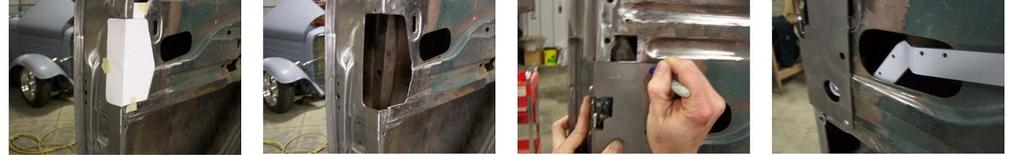
2 familiarize yourself with the lock and how it slips. Before installing your new latch kit make sure the lock is in the fully unlocked position. 5. Place provided template in position on the door by aligning the template tab along the bottom of the square hole (fig. 3) Take your time to align this template properly and then tape it in to place. (fig. 3a) Your template has 2 lines on the alignment tab. The top line is for use with the Tudor Sedan. All other doors will use the next line down as the alignment line. Trace around the template. Do not trace around the template tab. This is for alignment purposes. Use a ¼ drill to drill a hole in each of the four corners. This will assist you in making the cut with a saw. Proceed to cut out this section of the door. (fig. 4) When cutting the hole, tread lightly around the upper outside corner. The size of the plate and latch in this area does not allow for an over cut. It would be best to cut close to the line and file the opening to fit. 6. With the latch mounted to the plate, put the latch plate in place to make sure the opening you have cut will accept the assembly. Take your time and do not over cut this opening. This latch kit will fit in the hole it just requires a little finesse and patience. Once you get the latch assembly in place, mark the holes for attaching the plate to your door. (fig. 5) Remove the latch assembly and drill the holes using a ¼ drill bit. PLEASE READ BEFORE CONTINUING Before moving to the next step, this is a good time to lubricate your handles liberally at their pivot point. Work your handles several times and get them moving freely and smooth. While we did put a return spring on this kit it is not strong enough to fight against years of rust and grime. As stated our kit uses a return spring to assist the exterior handle in returning to a straight position. Some original handles have twisted shafts caused by years of stiff latches. This can usually be seen when holding the handle in ones hand. If this is the case with your handles you can put the handles shaft in a vise and use a little heat and muscle to twist the shaft back to a straight position. If you should happen to over grind your handle shaft causing your handle to drop, this can remedy that problem as well. If your exterior door handle has exposed mounting screws you can install the door handle after installing your new latch kit. However, if your door handle mounting screws are not exposed until you rotate the handle, you must install your exterior door handle before installing the latch plate. The rest of the instructions will assume you are using a handle without exposed mounting screws. 7. Securely install your exterior door handle back in your door. Note: This is a good time to liberally lubricate all moving latch and lock parts before its final placement in your door. We recommend using a marine quality grease.
3 8. Carefully place your new latch kit in place making sure to align your exterior handle shaft to the shaft receiver of the latch kit. Once the latch kit is in place attach it to your door using the ¼-20 button head bolts, lock washers, and nuts provided with your kit. 9. If you have not done so, detach your inside door handle strap from your factory door latch by pushing down on and rotating the strap. Locate the rivet connecting the strap to your interior door handle regulator. Grind this rivet and separate the strap from the regulator. 10. This latch kit includes a new strap to attach your interior door handle regulator to your new bear claw latch system. You will notice the strap has multiple holes, this is to give you some flexibility and adjustment when installing the strap. Attach the offset end of the strap to your latch using the screw and lock nut provided in your kit. (fig. 6) Do not over tighten, as this is a pivot point and must remain free to move. 11. Locate the hole on the other end of the strap that best aligns with your interior door regulator and using the provided screw and lock nut provided in your kit, attach the strap to your regulator. Just like the other end of the strap, do not over tighten, as this is a pivot point and must remain free to move. You will notice along the edge of the strap there are little notches. These notches represent the best hole placement we found through our testing. This is a good starting point and you can adjust from there. Once you have found the best hole to use for your application you can mark and cut off the excess length of the strap. Strap Notches: Coupe, Four door front doors, and Sedan Delivery - First notch Tudor Sedan - Third Notch You may find that your interior handle does not return to its normal position after releasing the latch. To remedy this you can attach a spring to the strap in one of any of the provided holes. The spring will assist the interior lever in returning to its correct position. 12. Install the supplied striker block. Place it where you feel the striker bolt will be centered with your latch assembly. Gently close your door paying close attention to clearance and how the door feels. If it climbs or drops while opening and closing adjust your striker block accordingly. Passenger Side Lock Cylinder Installation Please make sure all moving parts on latch assembly and lock assembly are well lubricated. 1. Measure and cut your lock cylinder shaft using the provided measurements. Pay close attention as there are different lengths depending on the model you have. (Fig. 7)
4 2. Make sure your latch kit is in the fully unlocked position, as well as your lock cylinder. 3. Reinstall your lock cylinder.


5
6
PLEASE READ THIS NOTICE BEFORE BEGINNING ANY PHASE OF INSTALLATION!!!!
 PLEASE READ THIS NOTICE BEFORE BEGINNING ANY PHASE OF INSTALLATION!!!! This kit is designed to be installed by someone with a fair amount of mechanical aptitude. However, if you are not comfortable making
1. Begin by rolling your window up all the way 2. Remove your door and window handles by unscrewing the flat head set screws behind each handle.
 1. Begin by rolling your window up all the way 2. Remove your door and window handles by unscrewing the flat head set screws behind each handle. 3. Remove the 12 screws that attach the steel interior door
RH-412 STEEL DOORS INSTALLATION INSTRUCTIONS
 RH-412 STEEL DOORS INSTALLATION INSTRUCTIONS By following the steps outlined below, the assembly, installation and adjustment of the steel doors, will be a simple process. Let s start with the Driver Side.
INSTALLATION INSTRUCTIONS RH 412 STEEL DOORS
 By following the steps outlined below, the assembly, installation and adjustment of the steel doors, will be a simple process. Let s start with the Driver Side. Note: Having the hood open makes the job
START HERE BEFORE YOU BEGIN FIG 1 STEP 2
 PROFESSIONAL INSTALL RECOMMENDED REAR MODULAR / MULTI LED ROOF MOUNTS PART#: Z350040 / Z350050 REAR ROOF LED LIGHT MOUNTS Parts included (1) - Driver Side Roof Mount Upright (1) - Passenger Side Roof Mount
Installation for Full Size Polaris Ranger Crew Doors
 Installation for Full Size Polaris Ranger Crew Doors Order of Installation: Heater Doors Wiper on to Windshield Windshield Top & Back Panel Note: Most of the steps in these instructions need to be repeated
Installing Your Electronic Deadbolt
 Ultra Security Plus Electronic Deadbolt Installation Instructions http://www.hberger.com/video-gallery/electronic-deadbolt New Installation Lock Location Preparation (Skip this section if you door has
RangerWare Fiberglass Door System Installation Instructions P/N
 Page 1 of 9 RangerWare Fiberglass Door System Installation Instructions P/N 2878016 ORDER OF INSTALLATION Note: To assure proper order, read all Accessory Installation Instructions before beginning. 1.
MORTISE LOCK INSTALLATION INSTRUCTIONS
 MORTISE LOCK INSTALLATION INSTRUCTIONS INSPIRE TM ROSELESS DESIGNER TRIM FM 340 Rev. 10/18 TABLE OF CONTENTS: DOOR PREPARATION 1 ML2000 LOCK HANDING 2 FULL WORKING TRIM (STD) 3 HALF WORKING TRIM (M30)
IMPORTANT: PLEASE RETAIN THIS INSTRUCTION MANUAL FOR FUTURE REFERENCE
 IMPORTANT: PLEASE RETAIN THIS INSTRUCTION MANUAL FOR FUTURE REFERENCE 005-07 Cadillac STS Classic 3D Z, Classic Dual Weave, Classic Mesh & Classic Black Mesh Grilles B 7 HR 3 STS Classic 3D Z Grille Part
Viewing the Ryca Motors CS-1 Build Video series at youtube.com/rycamotors is highly recommended before beginning the following assembly process.
 RYCA CS-1 ASSEMBLY GUIDE [The CS-1 installation guides should be used as supplements to the videos found on our Youtube Channel. There is no strict order to the build process, but it is highly recommended
1. Turn off or disconnect power to unit (machine). 2. Push IN the release bar on the quick change base plate. Locking latch will pivot downward.
. 2. Push IN the release bar on the quick change base plate. Locking latch will pivot downward.") Figure 1 Miniature Quick Change Applicators, of the end feed type, are designed to crimp end feed strip terminals to prestripped wires. Each applicator is set up to accept the strip form of certain specific
Figure 1 Miniature Quick Change Applicators, of the end feed type, are designed to crimp end feed strip terminals to prestripped wires. Each applicator is set up to accept the strip form of certain specific
INSTALLATION INSTRUCTIONS 3"/4 BENT END SIDEBARS FORD F-150 SUPERCREW PART # DZ /DZ
 INSTALLATION INSTRUCTIONS 09-12 FORD F-150 SUPERCREW PART # DZ 372697/DZ 372699 PARTS LIST: 1 Driver/Left Sidebar 4 1/2 Lock Washers 1 Sidebar 4 12mm x 32mm OD x 3mm Flat Washers 1 Driver/Left Mounting
INSTALLATION GUIDE Rear Bumper. Jeep JL Wrangler
 INSTALLATION GUIDE Rear Bumper Jeep JL Wrangler Dual Swing System 1A From the stock bumper you removed from vehicle, you ll need to take the parking sensor wiring from it and feed it into the new bumper.
STENCIL MACHINE OPERATION uline.com H-259, H-347 H-408 CUTTING THE OIL BOARD INSERTING THE OIL BOARD
 H-259, H-347 H-408 π STENCIL MACHINE 1-800-295-5510 uline.com OPERATION NOTE: No assembly is necessary after you unpack your machine. INSERTING THE OIL BOARD 1. Move the release lever to the right. This
INSTALLATION GUIDE 2009-CURRENT HUMMER H3T PRODUCT CODE:
 INSTALLATION GUIDE 2009-CURRENT HUMMER H3T PRODUCT CODE: 268 June 22, 2010 TOOLS NEEDED COMPONENTS INCLUDED P2 Tip 3/8" Drill Rubber Gasket(s) x 2 Bracket(s) x 2 1/2" Drill Bit Bulkhead Flange #2 Phillips
INSTALLATION INSTRUCTIONS
 TEL -866-XANATOS INSTALLATION INSTRUCTIONS PART#: 7D5000SS\7D500A GRILL GUARD FOR DODGE SPRINTER 07-09 PARTS LIST: 8 6 Grille Guard Driver/Left Frame Mounting Passenger/Right Frame Mounting Driver/Left
After the canopy hinge is square with the firewall and the nut plates are installed you can set up the hinge mounts. Start by clamping a 1/16 tongue
 Written by: Sean Cole September 19, 2008 When fitting the stiffener use 3/32 clecos to hold it in place, it makes a smaller hole and is easier to work with. Only use the amount needed to hold the stiffener
Please read BOTH these Installation Instructions and the General Instructions before attempting to install or operate this equipment.
 Please read BOTH these and the General Instructions before attempting to install or operate this equipment. 1. Blue Ox towing products and accessories are intended to be installed by Blue Ox Dealers who
8mm x 25mm "Z" Bolt Plates. (2) Tube Spacers. (2) 12mm Bolt Plates w/ Nut
 Tube Spacers. (2) 12mm Bolt Plates w/ Nut") PARTS LIST: 1 Grille Guard 10 12mm Lock Washers 1 Driver/Left Side Frame Mounting Bracket 8 12mm Hex Nuts 1 Passenger/Right Side Frame Mounting Bracket 2 10-1.50mm x 25mm Button Head Bolts 1 Driver/Left
PARTS LIST: 1 Grille Guard 10 12mm Lock Washers 1 Driver/Left Side Frame Mounting Bracket 8 12mm Hex Nuts 1 Passenger/Right Side Frame Mounting Bracket 2 10-1.50mm x 25mm Button Head Bolts 1 Driver/Left
Jeep Wrangler JK & 4-Door Front Pair Part # Revision H
 Jeep Wrangler JK 2007 2 & 4-Door Front Pair Part # 10045 Revision H 03-25-09 Step 1: Prior to Installation: A) Bushwacker only approves installing the flares according to these written instructions with
ED1300/1300F SERIES CONCEALED VERTICAL ROD DEVICE INSTALLATION INSTRUCTIONS
 ED1300/1300F SERIES CONCEALED VERTICAL ROD DEVICE INSTALLATION INSTRUCTIONS Ver.2 1300 SERIES CONCEALED VERTICAL ROD DEVICE Top Strike Latch Screws Strike Screws Release Plunger Top Latch Plunger Screws
JK Crusher Corners. *Includes ONE of the Hardware Kits (not both)
") INSTALLATION INSTRUCTIONS INST-18-05-020_A JK Crusher Corners IMPORTANT: Thank you for purchasing this Poison Spyder product. Please read through this entire document before proceeding with installation.
INSTALLATION INSTRUCTIONS INST-18-05-020_A JK Crusher Corners IMPORTANT: Thank you for purchasing this Poison Spyder product. Please read through this entire document before proceeding with installation.
TOOLS REQUIRED FOR INSTALLATION: AIR RACHET, GRINDER AND CUTTER.
 THIS KIT INCLUDES: 16 M8-1.25X30MM BOLTS WITH WASHERS 2 SHOCKS 565 PSI RIGHT AND LEFT HINGE ASSEMBLY 2 SHOULDER BOLTS 2 PINS TOOLS REQUIRED FOR INSTALLATION: AIR RACHET, GRINDER AND CUTTER. 7/23, 10MM,
WPS crew Doors Installation instructions
 WPS-132-133 crew Doors Installation instructions ORDER OF INSTALLATION FOR A COMPLETE ENCLOSURE OF A CREW WPS (Weather Protection System) IS AS FOLLOWS: 1. Heater 2. Rear Thresholds - Right Hand & Left
Page 1 of 12 GENERAL INSTRUCTIONS KHJKK Installation
 Page 1 of 12 KHJKK PICTURE ABOVE IS THE UNIVERSAL KIT; YOUR KIT MAY BE DIFFERENT. THIS KIT INCLUDES: 8 M8-1.25X30MM BOLTS WITH WASHERS 8 M8-1.25X40MM BOLTS WITH WASHERS 2 PINS RIGHT AND LEFT HINGE ASSEMBLY
Precision Steel Car s 100 T Steel Coil Car
 Precision Steel Car s 100 T Steel Coil Car Precision Steel Car www.precisionsteelcar.com info@precisionsteelcar.com Paul Vernon: (513) 571-5739 Revised 4/30/2009 Contents of Kit Main Tube Side Frame 2
4600 Series Rim Narrow Stile Exit Device Installation Instructions I-ED01162
 DEVICES COVERED IN THIS DOCUMENT: 4600 Series Rim Panic Narrow Stile Exit Device 4600 Series Rim Fire Narrow Stile Exit Device OVERVIEW Outside of Door RHR LHR Inside of Door APPLICATIONS 4950 BLADE STOP
Congratulations! You are now on your way to enriching your life with! Figure #5. Step 5 Install the Dummy Deadbolt. Step 3 Drill the Door
 C) Using the base point as your reference, measure up 8-1/32 and mark a horizontal line. Measure in from the edge of the door the distance of your backset and mark where the two lines cross. This will
OTHER TOOLS MAY BE NEEDED DEPENDING ON YOUR VEHICLE.
 THIS KIT INCLUDES: 16 M8-1.25X40MM BOLTS WITH WASHERS 2 SHOCKS 720 PSI RIGHT AND LEFT HINGE ASSEMBLY 2 SHOULDER BOLTS 2 PINS TOOLS REQUIRED FOR INSTALLATION: AIR RACHET, GRINDER AND CUTTER. 10MM, 11MM,
INSTALLATION INSTRUCTIONS
 AUTOMOTIVE PRODUCTS, INSTALLATION INSTRUCTIONS PLATINUM 4 OVAL STEP BAR (90 BENT END) APPLICATION: 2010-2015 Dodge Ram 2500/3500 Mega Cab PART NUMBER: 21-3570, 21-3575, 23-3570, 23-3575, 25-3570, 25-3575,
INSTALLATION INSTRUCTIONS REPLACING EXISTING DEADBOLT ASSEMBLY
 INSTALLATION INSTRUCTIONS REPLACING EXISTING DEADBOLT ASSEMBLY A B C L M N D E F G O P Q H I J Tools provided in Amesbury installation kit: (A) door router fixture, (B) doorframe router fixture, (C) ½
Technicians of Terror. This is the air valve we make to use with our air
 These are pictures of our scissor prop. Technicians of Terror http://www.halloweenfear.com/scissorprop.html props. This is the air valve we make to use with our air This pictures the duel door closer cylinders
Assembly Instructions 10 X 10 Aluminum Frame Building
 Assembly Instructions 10 X 10 Aluminum Frame Building 27 97 9 8 47 36 74 52 10 10 X 10 Square Building W/ Dome Includes: The Steel Entry Door with a Dead Bolt Lock assembly and Aluminum Door Frame. Metal
ASSEMBLY INSTRUCTIONS FOR MAR-K BEDSIDES AND GM FLUSH TAILGATE WITH HANDLE
 ASSEMBLY INSTRUCTIONS FOR MAR-K BEDSIDES AND 41-53 GM FLUSH TAILGATE WITH HANDLE Build the box assembly according to the MAR-K assembly instructions. When installing the tailgate and latching mechanisms
Replacing the Reciprocator on the SWF Compact Series Machine (601C and 1201C)
") Follow the instructions below to replace the reciprocator in the SWF Compact series machines. The tools required can be found in the tool kit that came with the machine. Preparation 1. First, place the
Follow the instructions below to replace the reciprocator in the SWF Compact series machines. The tools required can be found in the tool kit that came with the machine. Preparation 1. First, place the
INOVO 4-LITE SLIDING PATIO DOOR ASSEMBLY AND INSTALLATION INSTRUCTIONS
 INOVO 4-LITE SLIDING PATIO DOOR ASSEMBLY AND INSTALLATION INSTRUCTIONS IMPORTANT: READ THE INSTRUCTIONS AND FAMILIARIZE YOURSELF WITH THE DOOR PARTS AND PIECES BEFORE BEGINNING ASSEMBLY AND INSTALLATION.
C70 Window Roller Repair Taken from: Heres the problem:
 C70 Window Roller Repair Taken from: http://www.volvospeed.com/vs_forum/topic/115086-how-to-c70-window-rollers-permanent-fix/ Heres the problem: This happened to two separate window assemblys on my c70
Please read BOTH these Installation Instructions and the General Instructions prior to installing or operating this equipment.
 Attachment Tab Height: 16-1/4 Attachment Tab Width: 21-3/4 Please read BOTH these and the General Instructions prior to installing or operating this equipment. Serial Number 1. Blue Ox towing products
Pet Door Panel Installation Manual
 Pet Door Panel Installation Manual 400-558-1 1 4/3/03, 3:26 PM Components: Pet Door Panel Panel Latch Assembly Foam Weather-stripping Glass Sweep (4) Binding Posts (6) #6 x 1/2 Sheet Metal Screws (4) 8-32
WARNING BX1514. Serial Number Buick LaCrosse Installation Instructions
 Serial Number Please read BOTH these and the General Towing Instructions before attempting to install or operate this equipment. 1. Blue Ox towing products and accessories are intended to be installed
INSTALLATION INSTRUCTIONS 3 ROUND & 4 OVAL SIDEBAR (90-DEG BENT END) DODGE RAM MEGA CAB PART NUMBER SB1214S SB1214B
 DODGE RAM MEGA CAB PART NUMBER SB1214S SB1214B") INSTALLATION INSTRUCTIONS PART NUMBER SB1214S SB1214B PARTS LIST: Qty Description Qty Description 1 Driver/Left Sidebar 4 12mm x 32mm OD x 3mm Flat Washers 1 Passenger/Right Sidebar 4 12mm Lock Washers
INSTALLATION INSTRUCTIONS PART NUMBER SB1214S SB1214B PARTS LIST: Qty Description Qty Description 1 Driver/Left Sidebar 4 12mm x 32mm OD x 3mm Flat Washers 1 Passenger/Right Sidebar 4 12mm Lock Washers
Hardware Installation. Do this first:
 1 Do this first: Hardware Installation Need some help? Here s what you ll need: 4 AA Batteries Phillips screwdriver Visit us online. support.remotelock.com We re here to help. 1 (877) 254 5625 support@remotelock.com
OVERVIEW. Mounting Post (2 places) Cylinder Cam. Handing Pin
 Cylinder Cam. Handing Pin") DEVICES COVERED IN THIS DOCUMENT: 46CE Cylinder Escutcheon Key locks and 46DT Dummy Trim Pull when dogged unlocks lever 46BE Blank Escutcheon Always operable 46NL Night Latch Key retracts latchbolt 46NK
DEVICES COVERED IN THIS DOCUMENT: 46CE Cylinder Escutcheon Key locks and 46DT Dummy Trim Pull when dogged unlocks lever 46BE Blank Escutcheon Always operable 46NL Night Latch Key retracts latchbolt 46NK
Quick-Release Sliding Tail Vise 05G30.01
 Quick-Release Sliding Tail Vise 05G30.01 U.S. Des. Pat. No. D671,812 U.S. Pat. No. 9,050,710 Introduction The Veritas Quick-Release Sliding Tail Vise is a reworked version of the well-known tail vise that
Replacement PVCu Door Lock
 Replacement PVCu Door Lock Universal replacement lock designed to fit most PVCu doors Pack contents Lock Fixing tab Keep Before you begin Please read these instructions carefully Following the steps in
D3976 RECESSED EXIT INSTALLATION INSTRUCTIONS
 PACKAGE CONTENTS PRODUCT MUST BE INSTALLED ACCORDING TO ALL APPLICABLE BUILDING AND LIFE SAFETY CODES TEMPLATE INSTALLATION INSTRUCTIONS STRIKE HAND TOOL 5/32 HEX KEY ROD END CAPS EXIT DEVICE CRANK ARM
GRILLE GUARD SPRINTER VAN (EXCLUDES X4) INCLUDES MERCEDES, FREIGHTLINER AND DODGE PARTS LIST:
 INCLUDES MERCEDES, FREIGHTLINER AND DODGE PARTS LIST:") PARTS LIST: 1 Grille Guard 8 12mm Hex Nuts 1 Driver/Left Side Frame Mounting Bracket 2 10-1.50mm x 25mm Button Head Bolts 1 Passenger/Right Side Frame Mounting Bracket 4 10mm x 20mm OD x 2mm Flat Washers
PARTS LIST: 1 Grille Guard 8 12mm Hex Nuts 1 Driver/Left Side Frame Mounting Bracket 2 10-1.50mm x 25mm Button Head Bolts 1 Passenger/Right Side Frame Mounting Bracket 4 10mm x 20mm OD x 2mm Flat Washers
YJ DeFenders. These installation instructions apply to the following Poison Spyder products:
 INSTALLATION INSTRUCTIONS INST-13-02-070_A YJ DeFenders IMPORTANT: Thank you for purchasing this Poison Spyder product. Please read through this entire document before proceeding with installation. If
Clayton Off Road COR COR COR
 Clayton Off Road COR-4806011 COR-4806021 COR-4806031 JEEP GRAND CHEROKEE WJ LONG ARM UPGRADE KITS (1999-2004 WJ) NOTES: This product requires general welding, fabrication and automotive mechanic skills.
WARNING!! DO NOT LIFT DOORS UP WHEN THE HOOD IS OPEN. THE DOORS WILL HIT THE HOOD!
 WARNING!! DO NOT LIFT DOORS UP WHEN THE HOOD IS OPEN. THE DOORS WILL HIT THE HOOD! THIS KIT INCLUDES: 4 M8-1.25X30MM BOLTS WITH WASHERS 12 M8-1.25X40MM BOLTS WITH WASHERS 2 SHOULDER BOLTS WITH RIGHT AND
Please read BOTH these Installation Instructions and the General Instructions prior to installing or operating this equipment.
 2012-14 Chevy Captiva Sport Attachment Tab Height: 21-1/2 Serial Number Attachment Tab Width: 18-1/2 Please read BOTH these and the General Instructions prior to installing or operating this equipment.
TOOLS REQUIRED Metal Wood Wood and Metal Screws. #16 Drill #12-24 Tap. 1/8 Drill
 DEVICES COVERED IN THIS DOCUMENT: 4700S Surface Vertical Rod Device 4700SF Fire Exit Surface Vertical Rod Device TOOLS REQUIRED Metal Wood Wood and Metal Screws Sex Bolts #7 Drill ¼ -20 Tap #16 Drill #12-24
BX Toyota Tacoma (Includes Prerunner) Installation Instructions
 Installation Instructions") Attachment Tab Height: 11.5 Attachment Tab Width: 30.5" Serial Number Please read BOTH these and the General Instructions prior to installing or operating this equipment. 1. Blue Ox towing products and
Attachment Tab Height: 11.5 Attachment Tab Width: 30.5" Serial Number Please read BOTH these and the General Instructions prior to installing or operating this equipment. 1. Blue Ox towing products and
Please read these Installation Instructions in their entirety prior to installing or operating this equipment.
 2014-2017 Ram 2500 (All beds) Please read these in their entirety prior to installing or operating this equipment. This hitch is rated to 30,000 lbs. Gross Towing Weight and 7,500 lbs. Tongue Weight Bolt
TOOL LIST FOR TAILGATE HIDDEN LATCH & LINK ASSY FOR FORD FLARESIDE TRUCKS
 TOOL LIST FOR TAILGATE HIDDEN LATCH & LINK ASSY FOR 53-87 FORD FLARESIDE TRUCKS Vise Grip Clamps C-clamps Sharpie Marker Ball Peen Hammer Center Punch 3/8 or 1/2 Drill 5/32, 7/32, 9/32, and 3/8 Drill Bits
Rudder Pedal Kit. Assembly Manual. V1.0 July 2010.
 Rudder Pedal Kit Assembly Manual V1.0 July 2010. Introduction: Thank you for your purchase of our Boeing 737 Rudder Pedal Kit. many years of faithful service from our product. We hope you will have Our
CORVETTE Page 1 of 12 CORVETTE C
 CORVETTE 2005-2006 Page 1 of 12 CORVETTE C5 1997-2004 THIS KIT INCLUDES: 8 M8-1.25X40MM BOLTS WITH WASHERS 8 M8-1.25X30MM BOLTS WITH WASHERS RIGHT AND LEFT HINGE ASSEMBLY WIRE LOOM 2 SHOCKS 565 PSI 2 SHOULDER
INSTALLATION INSTRUCTIONS PART#:17GT23MSS\17GT23MA MODULAR GRILL GUARD FOR CHEVY SILVERADO 1/2 TON 99-02
 INSTALLATION INSTRUCTIONS PART#:17GT23MSS\17GT23MA MODULAR GRILL GUARD FOR CHEVY SILVERADO 1/2 TON 99-02 1 guard, center section 1 brush guard, left side 1 brush guard, right side 1 wire guard insert,
Double Screen Door Installation Instructions
 Double Screen Door Installation Instructions (36) #8x1 tek screws (20) #8x1/2 tek screws Package Includes: (2) PCA Screen Doors (1) Astragal (1) Left Hand Z-bar (1) Right Hand Z-bar (1) Header Z-bar (2)
BILLET SUICIDE HINGE INSTALL INSTRUCTIONS
 BILLET SUICIDE HINGE INSTALL INSTRUCTIONS Note Before Installing Installing suicide hinges is a very involved project. These instructions are general in nature because every car and every install will
INSTALL/REMOVAL INSTRUCTIONS: WINDOW REGULATOR
 REMOVAL/INSTALL OF WINDOW REGULATOR (740-666) Lincoln Town Car 1990 94 General Tech Tips: Use painter s tape rather than duct tape to secure window. It will not damage paint or leave sticky residue. A
CHEVY/GMC SuperRail Mounting Kit #3117
 CHEVY/GMC SuperRail Mounting Kit #3117 #3100 SuperGlide (12K) Gross Trailer Weight (Maximum) Vertical Load Weight (Max. Pin Weight) 12,000 lbs. 3,000 lbs. Installation Instructions SPECIFICATIONS Fits
INSTALLATION INSTRUCTIONS
 TEL:1-866-XANATOS INSTALLATION INSTRUCTIONS PART#: 17A110200MSS\17A110200MA MODULAR GRILL GUARD FOR NISSAN FRONTIER 05-10//PATHFINDER 05-07 1 guard, center section 1 brush guard, left side 1 brush guard,
CL4500 Installation Instructions
 CL4500 Installation Instructions Box Contents Check the contents of the box are correct according to the model 4510 4520 1 Front Plate 2 Back Plate 3 Lever Handles 4 Gaskets 5 Sprung Spindle (x1) 6 Spring
RAMPAGE P R O D U C T S. INSTALLATION INSTRUCTIONS BRONCO ZIPPER FASTRACK TOP PART #984xx BRONCO TOOLS REQUIRED
 RAMPAGE P R O D U C T S 84 (+/- 1/4 ) INSTALLATION INSTRUCTIONS BRONCO ZIPPER FASTRACK TOP PART #984xx BRONCO 1966-1977 TOOLS REQUIRED 3/8 WRENCH 7/16 WRENCH ½ WRENCH #2 PHILLIPS SCREWDRIVER 1/8 DRILL
WARNING Mercedes Smart for two CDI Installation Instructions BX1990. Serial Number
 Please read BOTH these and the General Instructions before attempting to install or operate this equipment. 1. Blue Ox towing products and accessories are intended to be installed by Blue Ox Dealers who
THIS KIT INCLUDES: 8 M8-1.25X40MM BOLTS WITH WASHERS 8 M8-1.25X30MM BOLTS WITH WASHERS RIGHT AND LEFT HINGE
 Sal es@lambodoorscanada. com 2407A Kal adarave,ottawa,on K1V 8B9 THIS KIT INCLUDES: 8 M8-1.25X40MM BOLTS WITH WASHERS 8 M8-1.25X30MM BOLTS WITH WASHERS RIGHT AND LEFT HINGE 2 SHOCKS 565 PSI 2 SHOULDER
STYLE BAR & TONNEAU COVER INSTALLATION
 STYLE BAR & TONNEAU COVER INSTALLATION INSTALLATION MANUAL: 2005 to '09 Mustang P/N: 10-8002-C12071B Saleen Performance, Inc. 1225 East Maple Rd., MI 48083 800-888-8945 www.saleen.com 1 IF YOU ARE NOT
J D SQUARED INC. NOTCH MASTER Tube and Pipe Notcher Operating Instructions
 Copyright (c) 2006 J D SQUARED INC. www.jd2.com NOTCH MASTER Tube and Pipe Notcher Operating Instructions Angled Notches PATENT PENDING Straight Notches Offset Notches Tube Clamp Slider Tube Clamp Exploded
Tools Required. * When installing on a fire door, please see instructions below. *
 CL615 Tubular Mortice Latch with Code Free option CL615 Tubular Mortice Latch with Code Free option Number relating to picture Item 1 Front Plate and handle * 2 Back Plate and handle * 3 Neoprene seals
ABM International, Inc.
 ABM International, Inc. Lightning Stitch required 1 1.0: Parts List head and motor assembly (Qty. 1) Reel stand (Qty. 1) Needle bar frame clamp (Qty. 1) Motor drive (Qty. 1) 2 Cable harness with bracket
CORVETTE CORVETTE REV: Made in USA U.S. PATENT #6,808,223; #6,845,547; #7,140,075; #7,059,655 and other patents pending.
 CORVETTE 2005-2006 CORVETTE 2005-2007 REV: 7-2-07 Made in USA U.S. PATENT #6,808,223; #6,845,547; #7,140,075; #7,059,655 and other patents pending. Page 1 of 12 CORVETTE C6 2005-2007 THIS KIT INCLUDES:
Please read BOTH these Installation Instructions and the General Instructions prior to installing or operating this equipment.
 1997-2006 Jeep Wrangler (Includes Rugged Ridge Double Tube Bumper) Attachment Tab Height: 17-3/4 Serial Number Attachment Tab Width: 24 Please read BOTH these and the General Instructions prior to installing
Installation Instructions II-2/4/5K-0608
 Installation Instructions II-2/4/5K-0608 Box Contents Check the contents of the box are correct according to the model 2010 4010 4020 5010 5020 1 Front Plate 2/4000 - - 2 Front Plate 5000 - - - 3 Back
VIT SB-16SS Pedestal. Conversion Guide
 Converting a to Baseline This guide describes the steps for removing another manufacturer s irrigation controller from a VIT SB-16SS pedestal and installing a Baseline controller. Remove All Parts of the
Feed Drawer Rebuild, for Models, 22HF, 16HF, 1600 machines
 Knowledge Base Article Type: Instructions Feed Drawer Rebuild, for Models, 22HF, 16HF, 1600 machines Description: Instructions on How to properly remove and rebuild a Feed Drawer. WARNING Never work on,
For installation assistance, contact SARGENT at DOORS SHOWN HERE SWING IN FOR ILLUSTRATION PURPOSES ONLY.
 SARGENT Installation Instructions for LP8600 x LR8600 & 12-LP8600 x 12-LR8600 Series Low Profile Panic and Fire Exit Devices on Double Egress & Double Doors or LS8600 & 12-LS8600 Low Profile Exit Device
Please read BOTH these Installation Instructions and the General Instructions prior to installing or operating this equipment.
 Attachment Tab Height: 13 Attachment Tab Width: 24 Please read BOTH these and the General Instructions prior to installing or operating this equipment. Serial Number 1. Blue Ox towing products and accessories
Introduction. Rocky Mountain Westy Swing Away Carrier Kit Installation Instructions
 Rocky Mountain Westy Swing Away Carrier Kit Installation Instructions Introduction Thank you for purchasing the Rocky Mountain Westy Swing Away Carrier Kit. We pride ourselves in the products we develop
INSTALLATION INSTRUCTIONS FOR INSTALLING T-SERIES EXTRA HEAVY DUTY LEVER LOCKSET
 HIGH EDGE 2 1/4"(57mm) 03079400070 INSTALLATION INSTRUCTIONS FOR INSTALLING T-SERIES EXTRA HEAVY DUTY LEVER LOCKSET IMPORTANT: THIS LOCK IS NON-HANDED. LOCK IS FACTORY PACKED PREADJUSTED FOR 1³ ₄" (45mm)
Installation Instructions
 DODGE RAM 2500 20K Industry Standard SuperRail Custom Mounting Kit #2336 Gross Trailer Weight (Maximum)...20,000 lbs. Vertical Load Weight (Max. Pin Weight)...5,000 lbs. SYSTEM TOW CAPACITY Please note,
98/9927. Devices covered by these instructions: Surface Vertical Rod Exit Device
 911375-00 Surface Vertical Rod Exit Device 98/9927 Installation Instructions Devices covered by these instructions: 98/9927 Surface Vertical Rod Exit Device 98/9927-F (Fire) Surface Vertical Rod Exit Device
INSTALLING YOUR NEW SPRING LIFT ARM KIT
 INSTALLING YOUR NEW SPRING LIFT ARM KIT 1. Measure the distance that the roof is to be raised. [If your lift system is completely non-functional, you will need to calculate or estimate this distance as
SPIDA SAW OPERATIONS MANUAL
 SPIDA SAW OPERATIONS MANUAL CM SERIAL NUMBER. OCTOBER 2000 CONTENTS Page description 1.) Contents 2.) Safety First 3.) CM Overview 4.) CM Specifications 5.) CM Installation 6.) CM Operation Setting the
INSTALLATION INSTRUCTIONS GRILLE GUARD RAM 1500 PART # 5058/5058-2
 INSTALLATION INSTRUCTIONS GRILLE GUARD PART # 5058/5058-2 PARTS LIST: Qty Description Qty Description 1 Grille Guard 8 12-1.75mm x 35mm Hex Bolts 2 Upper Frame Mounting s (for trucks without tow hooks
Entry Mortise Lock Set Lever to Lever
 Entry Mortise Lock Set Lever to Lever 1 Lever 2 Escutcheon 3 Turn Piece 4 Mortise Lock 5 Scalp 6 Mortise Lock Strike 7 Mortise Lock Dust Box 8 Mortise Cylinder 9 Cylinder Swing Cover 10 Spindle 11 Spindle
INSTALLATION MANUAL FORTRESS SERIES
 Guardian Security Structures TEL 1-406-212-2334 EMAIL rg@gssdoors.com WEB www.gssdoors.com FORTRESS SERIES GENERAL INSTALLATION GUIDELINES 1. The door frame is installed using 16 bolt screws 7,5 mm in
Mallet Painting equipment Pop rivet gun
 RotorWay International Page A Body Check, Paint, and Interior Liners Procedures covered in this section: Assemble body apart from airframe and check overall fit; remove tail boom; fit and install eyebrow
Front Vise 70G G08.02
 Front Vise 70G08.01 70G08.02 The following instructions guide you through the installation of either the Regular Front Vise (70G08.01) or the Large Front Vise (70G08.02). The first step is to determine
INSTALLATION INSTRUCTIONS DODGE RAM 2 & 4WD 1500 PART # P5058
 INSTALLATION INSTRUCTIONS 2009-13 DODGE RAM 2 & 4WD 1500 PART # P5058 PARTS LIST: Qty Description Qty Description 1 Grille Guard 12 12-1.75mm Hex Nuts 2 Upper Frame Mounting s (for trucks without tow hooks
CHEVY/GMC SuperRail Mounting Kit #4423
 CHEVY/GMC SuperRail Mounting Kit #4423 #4100 SuperGlide (16K) #4400 SuperGlide (20K) Gross Trailer Weight (Maximum) Vertical Load Weight (Max. Pin Weight) 16,000 lbs. 4,000 lbs. Gross Trailer Weight (Maximum)
Instructions for the installation of Ellison Bronze balanced door models #137 & 138
 1. A packing list will be found in crate No. 1 of each shipment. The parts in the crates should be checked with this list. If there is any discrepancy, notify Ellison Bronze at once. 2. All parts are numbered.
INSTALLATION INSTRUCTIONS 3 BULL BAR 99-04, 04 "HERITAGE" F-150/250LD 2WD, 97-04, 04 "HERITAGE" 4WD WD EXPEDITION/ WD EXPEDITION PART
 INSTALLATION INSTRUCTIONS 3 BULL BAR PART #B-F1971;B-F2971 PARTS LIST: 1 Bull Bar 2 12-1.75mm x 130mm x 40mm Hex Bolts 1 Driver/Left Mounting Bracket 4 12-1.75mm x 35mm Hex Bolts 1 Passenger/Right Mounting
WARNING. BX Dodge Durango. Serial Number
 Please read BOTH these Installation Instructions and the General Towing Instructions before attempting to install or operate this equipment. 1. Blue Ox towing products and accessories are intended to be
Rim-Lock Door Set Installation Instructions
 Rim-Lock Door Set Installation Instructions Let s get started Check Your Parts List Two Doorknobs with Set Screws B. Doorknob Spindle C. Rim Lock with Mounting Screws D. Keeper with Mounting Screws E.
Hardware and Components:
 Hardware and Components: (A) 4X 5/16 x 1 Carriage Bolt (B) 2X 5/16 x 2-1/4 Carriage Bolt (C) 2X 5/16 x 3-1/4 Hex Bolt (D) 2X 5/16 x 3/4 Hex Bolt (E) 2X 5/16 x 1-1/4 Hex Bolt (F) 5/16 x 2-1/4 Hex Bolt (G)
Tech Sheet. T4 Interior conversion kit how to - fitting instructions. 1. Rear seat belts. 2.
 Page 1 of 8 T4 Interior conversion kit how to - fitting instructions Thank you for purchasing our T4 interior conversion kit. This kit will enable you to convert any SWB left hand loading door T4 into
Shepherd 210A Fingerprint Door Lock Installation Manual V1.1
 Shepherd 210A Fingerprint Door Lock Installation Manual V1.1 Hongda USA Inc. 2505 Technology Dr. #2-6A, Hayward, CA 94545, USA Phone: (510) 887-5682 Fax: (510) 372-0487 Email: info@hongdausa.com Website:
BX Honda Accord Ex-L 2012 Honda Accord SE Installation Instructions
 Please read BOTH these and the General Instructions before attempting to install or operate this equipment. Serial Number 1. Blue Ox towing products and accessories are intended to be installed by Blue