windoware designer collection AUSTRALIA hospitaltracks
|
|
|
- Barnaby Boyd
- 5 years ago
- Views:
Transcription

1 designer collection AUSTRALIA hospitaltracks M O N O T R A C K S Y S T E M S

2
3 designer collection C o n t a c t s f o r O r d e r s a n d E n q u i r i e s A U S T R A L I A SOUTH AUSTRALIA 21A Nelson Street, Stepney 5069 Phone (08) Fa (08) sasales@.net.au QUEENSLAND 40 Parramatta Road, Underwood 4119 Phone (07) Fa (07) qldsales@.net.au TASMANIA 2/14 Lamb Place, Cambridge 7170 Phone (03) Fa (03) tassales@.net.au NEW SOUTH WALES 7 Tait Street, Smithfield 2164 Phone (02) Fa (02) nswsales@.net.au CANBERRA 3 Sleigh Place, Hume ACT 2620 Phone (02) Fa (02) actsales@.net.au VICTORIA 9 Lambeck Drive, Tullamarine 3043 Phone (03) Fa (03) vicsales@.net.au Australia: Phone M C P A U S T R A L I A & N E W Z E A L A N D MCP NEW ZEALAND C/- MCP New Zealand Ltd. 45 Disraeli Street, Addington Christchurch New Zealand Telephone: Facsimile: mcpnz@.co.nz MCP AUSTRALIA C/- MCP Australia Pty. Ltd. 9 Suttor Street, Silverwater Sydney, NSW 2128 Australia Telephone: Facsimile: Customer Service: customerservice@.com.au A s s o c i a t e d C o m p a n i e s UNITED STATES OF AMERICA Sullivans (USA) Inc Middaugh Avenue Downers Grove, IL USA Telephone Facsimile Orders sulnotions@sbcglobal.net NEW ZEALAND Sullivans Enterprises (NZ) Ltd. 28 Sir William Avenue East Tamaki Auckland Telephone: Facsimile: orders.service@sullivans.co.nz AUSTRALIA 40 Parramatta Road, Underwood Brisbane Qld Telephone (07) Facsimile (07) Orders orders@sullivans.net


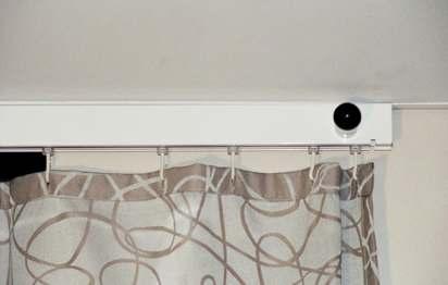
4 Series 9000 Monotrack rigid rail, moving rail, shower track, IV equipment and curtain cassettes Ideal for use in hospital casualty, intensive care, retirement homes, dental and doctor surgeries for fleibility of bed space. The Monotrack moving rail system enables fleibility and use of IV equipment. MONOTRACK FEATURES include fied rail system, curtain cassette available for ease of curtain removal and replacement when laundering. Installation hardware readily available for all types of applications. This manual covers the architectural specifications, complete component reference, component applications, installation instructions and suggested layouts. Also features IV equipment and cassette loaders for curtains. PLEASE NOTE: DUE TO THE VARIATION IN REQUIREMENTS, ALL PRICING FOR MADE TO MEASURE HOSPITAL TRACK WILL BE BY QUOTATION ONLY. 1
 E Q U I P M E N T C U R T A I N C A S S E T T E S Y S T E M 2")
5 architecturalspecifications S E R I E S M O N O T R A C K R I G I D R A I L B E D S C R E E N T R A C K S L O T T E D T R A C K F O R M O V I N G R A I L S Y S T E M S M I N I M O N O T R A C K F O R S H O W E R C U B I C L E S I V ( I N T R A V E N O U S ) E Q U I P M E N T C U R T A I N C A S S E T T E S Y S T E M 2


6 3


7 architecturalspecifications SERIES 9000 MONOTRACK (BEDSCREEN RAIL) ALUMINIUM RIGID RAIL SYSTEM The Series 9000 Monotrack is manufactured from aluminium and available in clear anodised and white epoy finish (refer components page for track colour and lengths available). Track section is 38mm height and 20mm width overall. This is suspended on aluminium tubular hangers supported from the structural ceiling and fied at the height shown on drawings. Refer installation page. TRACK DETAILS TRACK SECTION 38mm 20mm RAIL SPAN Windoware s solid Monotrack can span to a length of 3 metres from wall to wall without having any supports - saving you time and money. The solid Monotrack can be ceiling mounted or suspended. Can be suspended or ceiling mounted FOR A QUOTE PLEASE PHONE
 is 38mm in height and 20mm in width overall.")
8 architecturalspecifications SLOTTED MONOTRACK PATENTED MOVING RAIL SYSTEM Slotted Monotrack is used to operate a moving rail system allowing you to change cubicle sizes. TRACK DETAILS TRACK SECTION 38mm 20mm Track section 10369/Silver 10370/ (6m lengths only) is 38mm in height and 20mm in width overall. Main front rails and head rails are slotted to allow for movement of the trolley, which allows you to connect the rigid rail Monotrack Series PLEASE NOTE: When ordering tracks, don t forget the track sockets and curtain hooks 5


9 architecturalspecifications MINI MONOTRACK FOR SHOWER CUBICLES Mini Monotrack manufactured from aluminium, available in silver or white epoy finish, this Mini Monotrack is suited for shower tracking or lightweight screens. TRACK DETAILS TRACK SECTION 25mm 20mm Track section 10371/Silver 10372/ (6m lengths only to be 25mm height and 20mm width overall. Manufactured from aluminium in clear anodised or white epoy finish, can be suspended or ceiling fi. PLEASE NOTE: Standard sizes are available at 1m 1m or 2m 2m 6


10 architecturalspecifications IV (INTRAVENOUS) EQUIPMENT IV COMPONENTS The oval installation is good for operating rooms and intensive care giving complete freedom of movement around beds wherever it is installed for intravenous feeding. The IV Carrier is fitted with 2 nylon wheels and is constructed to create a 5 point suspension system with a stainless steel safety hook attached to the carrier body. MONOTRACK WITH IV CARRIER MONOTRACK SOLID MONOTRACK SLOTTED The intravenous track and carrier are normally supplied and installed as a U shape track in half the width of the bed. This then allows up to 5 intravenous drip systems to drop to the patient without interference. IV CARRIERS IV Tree Carrier Silver IV Tree Carrier Self Locking IV Trolley Silver IV TREE Five Point IV Tree Adjustable, mm Etension and mm Etension. 7


11 architecturalspecifications CURTAIN CASSETTE SYSTEM CASSETTE INFORMATION The curtain cassette is designed to allow a quick and easy change of the curtain. The cassette sits 70cm from the end of the track. An interchange of curtains can occur in one easy motion. INSTALLING CURTAIN CASSETTE SYSTEM These Curtain Cassette Loaders make bedscreen cubicle curtain changing quick and easy. Sturdy aluminium bo section matching the track system. 1. Insert curtain swivel hooks into Cassette insert 2. Place Cassette into the bridge at angle locating against post inside bridge 3. Withdraw release knob to assist final locking of insert 4. Draw the curtain along the track. To remove the curtain, reverse the procedure. 8


12 9

13 technicalspecifications C O M P O N E N T A P P L I C A T I O N A N D I N F O R M A T I O N 10


14 technicalspecifications COMPONENT APPLICATION AND INFORMATION COMPONENT APPLICATION SOLID TRACK Series 9000 Solid Monotrack for rigid rail tracking systems. This solid Monotrack is etruded from aluminium, suitable for high strength spanning. Standard finish is clear anodised and white epoy finish is also available. Can be bent or supplied pre-bent to specifications. Available in 4.0m, 6.0m and 7.4m lengths. SLOTTED TRACK Series 9000 Slotted Monotrack for moving rail tracking systems. Is etruded from aluminium, standard finish is clear anodised and white epoy finish is also available. Available in 6.0m lengths. Slotted track is made to accommodate the trolley, the heart of the moving rail system. This track cannot be bent, to achieve a bend you ll need to join a section of solid monotrack to the slotted track. (A) Dig A INTERNAL TRACK JOINER A two piece joiner complete with four screws, manufactured from aluminium which gives a rigid joint. The internal track joiner once in position, does not interfere with the runners in the track. Refer to Diagram A for accurate marking of holes to be drilled for clearance for screws. Note: This joiner is to be used for the Solid Monotrack only. Item No Silver JOINING SPLICE A right angle 40cm track joining splice is used for joining slotted track and Series 9000 Monotrack. Constructed from aluminium for a firm, rigid join. Can also be fitted with a single point hanger for suspension. Also used for butting up a straight track to a curved track (A). The joining splice is screwed to the top of both tracks to give the appearance of the tracks being one piece. Note: When butting up of straight track, don t forget the end stop. Item Silver Item A 11

15 technicalspecifications COMPONENT APPLICATION AND INFORMATION SINGLE POINT HANGER ASSEMBLY The single point hanger fies to the top of the track using a 12mm No. 6 countersunk selftapping screw. The suspension tube is locked in with a grub screw. COMPONENT APPLICATION Item No Silver Item No TWO POINT HANGER ASSEMBLY The two point hanger assembly fies to the top of the Monotrack using a 4.5mm No. 6 self-tapping screw. The suspension tube is locked in with a grub screw. Item No Silver Item No VEE HANGER ASSEMBLY The vee hanger assembly is used where a standard vertical drop is required and additional support to prevent sideways movement of the track. Note: Always ensure the maimum angle is 30deg between vertical and angled suspension tube. A swivel mount bracket (Item No 10407) is best used on the other end if fiing direct to ceiling. 30 Item No Silver Item No SUSPENSION TUBE CEILING COVER The suspension tube ceiling cover is supplied complete with rubber grommets. It grips onto the suspension tube and holds the cover in place. The function is decorative, used to cover the suspension collar and give a neat finish to the finished installation. Item No Silver Item No


 This end cap is fied to the side of the track.")

16 technicalspecifications COMPONENT APPLICATION AND INFORMATION COMPONENT APPLICATION TROLLEY ASSEMBLY The trolley is the key to the unique function of the moving rail system. Precision manufactured for ease of operation. The nylon wheels are complete with bearings and neoprene tyres. When fitting the trolley to solid track, it must be secured top and bottom of the track. Use a 12mm No. 6 self tapping screw. Item No A TRACK END STOP The track end stops are manufactured from PVC and are available in grey and white. The end stops are used to seal off the end of the Monotrack and to keep runners in and eliminate dust entering the track. Always fi to the track with a self tapping screw used as a right angle track joiner. Note: (A) This end cap is fied to the side of the track. Front Side Item No Grey Item No CEILING MOUNT CLIP These clips are used for flush mounting of the track to a ceiling. Manufactured from aluminium. Screw directly into the ceiling Then the track clips directly into the bracket. As an added safety precaution, a bolt can be passed through the track and the bracket to secure installation. WALL BRACKET (SIDE FIX) The wall bracket is constructed from steel. Fies to the top of the track with a 75mm projection Silver Side Swivel Mount Bracket SWIVEL MOUNT BRACKET This bracket is used where the suspension tube is fied to a stopped fiing point or you are using Vee Hangers this avoids the need to bend the tube Silver 13

17 installationinstructions S E R I E S M O N O T R A C K S L O T T E D T R A C K M I N I M O N O T R A C K 14
18 installationinstructions SERIES 9000 MONOTRACK 1. METHOD OF SECURING CEILING HANGER As in the case of all hanging methods, solid fiing must be available at the ceiling in the required positions which should be ascertained prior to the finished ceiling installation. In almost every case, some preparation is necessary, and it is advisable to discuss with the builder prior to installation 2. PLASTER ON TIMBER BATTENS Timber at batten level directly above the screen rail for the vertical rod and at a point adjacent to the vertical rod penetration for the angle rod if required (angle must not eceed 30º). 3. DIRECT TO EXPOSED CONCRETE SLAB Preparation is seldom required but light fittings and ceiling fans should be taken into consideration at the planning stage. Air conditioning ducts, pipes etc, in the area above the ceiling sometimes makes it necessary to fabricate special brackets for the support hangers. Ceilings in eisting buildings usually provide for the man holes to gain access. If is not possible to secure solid fiing, surface battens may be necessary. 4. SUSPENDED GRID CEILINGS It is not recommended that hangers be supported from suspended grids, ecept where additional strength has been provided for in the Architect s specifications. INSTALLATION For T joins use either a track socket or a track end stop FIGURE 1: T-Joins FIGURE 2: FIGURE 3: The recommended track height is 2100mm from floor to bottom of track unless otherwise indicated. Walls and ceilings should be inspected at contact positions to ensure that fiing is available at the shown height. KEY Straight Track Bend in Track Suspension Points 15 FIGURE 4:
 Then screw the hanger assembly into the ceiling ensure those are securely fastened. Use ceiling anchors or if it is preferable to screw directly to timber or something solid.")
19 installationinstructions SERIES 9000 MONOTRACK INSTALLATION WITH SUSPENSION TUBE HANGERS i) Put rail into position required and support it from the ground. ii) Then screw the hanger assembly into the ceiling ensure those are securely fastened. Use ceiling anchors or if it is preferable to screw directly to timber or something solid. iii) Then calculate the height required of the hanger tube to ensure the is at the correct height. iv) Hold the track up to where the tubes are hanging down and mark on the rail where the hanger assembly to the track must be places. v) Then screw the hanger assembly to the top of the track. Loosen alan key screws. vi) Now lift the track to the height required and place the hanger tubes into the hanger assembly and tighten the alan key screws. vii) If a dome is required to cover the hanger assembly in the ceiling this must be placed on the tube prior to connecting the track to the hanger tube. 16


20 installationinstructions SLOTTED TRACK MOVING CURTAIN RAIL SYSTEM 1 Track Height The recommended track height is 2100mm from floor to the bottom of the track, unless otherwise indicated. The main front rail and the head rail on the wall must be parallel and it may be found, particularly in the case of long runs in eisting buildings, that the head rail may have to be packed out to maintain a true line. 2 Consult the layout plan Consult the layout plan to determine positions of wall shoes and/or side fi brackets for support of main front rail. When the main front rail is assembled, remembering to insert trolleys prior to locking up, it may be laid out on the floor directly below its ultimate fied position. Determine hanger positions on the ceiling, and plumb onto rail for fiing positions of hanger connections. Fi ceiling anchors in pre-determined positions and attach hanger connections to rail. Attach hanger tubes to ceiling anchors and lift rail to required position, support on stilts if necessary. Cut tubes to length and tighten up in hanger collars with 3mm alan screws. 3 Connection of Moving Rail to Trolley Shoes During the installation of supporting rails, that is main front rail and parallel bed rail, place trolleys in appropriate rails and locate them in position opposite to one another. When installation of rails is complete, measure the distance between the centre lines of each rail. This measurement is the cutting length of the monorail to be inserted into trolley shoes. One end of the monorail is slid up into the end of the trolley shoe to its limit and care must be taken to hold rail at same angle of shoe and not to eert any downward pressure. Net, lift free end rail to the opening in bottom of opposite trolley shoe. 17

 be used in the centre of the main rail to offset possible side movement.")

21 installationinstructions SLOTTED TRACK CONTINUED 4 Where moving rails traverse Item No Where Moving rails traverse past a ceiling hanger attachment, two point hanger plate (Item No 10405) should be used. Where necessary to join main front rail a right angled joiner should be used. This serves as a joiner and hanger combination support. Item No Recommended traverse of the moving rail is restricted to area between pairs of beds. If moving rails are required to be moved to ends of wards, it is recommended that a V Hanger (Item No 10401) be used in the centre of the main rail to offset possible side movement. Then the vertical leg of the V Hanger should not be tightened in position until the moving rail is travelling freely, directly at that point. HANGER SUPPORT SHOULD NEVER BE FURTHER THAN 600mm FROM A BEND 5 When the installation is complete Moving rail traverse should be carefully checked and traverse stops tightened in corresponding positions on both head and front rails to ensure traverse distance is the same on both rails to ensure traverse distance is the same on both rails. All ends should be cut square, preferably with a circular power saw and carefully de-burred prior to joining. Inaccurate joins must be rectified to allow free travel of trolley and curtain runners. Monotrack Slotted track Slotted track 18


22 installationinstructions MINI MONOTRACK INSTALLING SHOWER TRACK SYSTEM 1. Attach track socket onto wall with counter sunk screws. Track socket Shower wall 2. Cut track with hacksaw to suit eact size. NB For etra support you can use a ceiling bracket or suspended tube. 3. Insert curtain hooks into track. 4. Drop rail into socket into each end, then fasten with counter sunk screws. Track Shower wall 19

23 suggestedlayouts T Y P I C A L W A R D L A Y O U T B E N D S A N D S E T S T Y P I C A L T W O B E D L A Y O U T 20


24 suggestedlayouts TYPICAL WARD LAYOUT TYPICAL WARD LAYOUT corridor Figure 1 - Single Room with corridor window and door screened with one track. Figure 2 - Two or Four bed mobile Figure 3 - Two rails parked at end can be used for economy screening of two end beds or one continuous centre bed. Head rail must be continuous. Corridor rail requires stablising with V hanger and horizontal brace. TYPICAL BENDS AND SETS All bends 250mm radius 1000mm minimum 0º to 90º bends 135º 135º 21
25 suggestedlayouts TYPICAL TWO BED LAYOUT USING MONOTRACK Install all Monotrack to a detail drawing selecting correct parts to be added. Eamine walls and ceilings to determine adequate supports available. Where false ceilings are used above ceiling pre-work may have to be done. Track is supplied in 4, 6 and 7.4 metre lengths, straight or with bends to your specifications. Form configurations on ground then attach to pre-fied wall shoes or brackets and ceiling hangers (use plumb line). Fi hangers near joins on the long length of the track side. All bends should be supported by a support. Solid Monotrack can stand up to 3 metres in straight height while fied wall to wall, no supports are required. RIGID FIGURE 1 FIGURE 2 FIGURE 3 KEY Straight Track Bend in Track Support Bracket Suspension Points FIGURE 4 FIGURE 5 MOBILE FIGURE 6 FIGURE 7 FIGURE 8 FIGURE 9 22

26 23


 E Q U I P M E N")
27 componentsreference S E R I E S M O N O T R A C K C O M P O N E N T S M I N I T R A C K A N D C O M P O N E N T S I V ( I N T R A V E N O U S ) E Q U I P M E N T 24
28 monotrackcomponents QUICK REFERENCE GUIDE IMAGE ITEM No DESCRIPTION SIZE COLOUR/FINISH PACK MONOTRACK HOSPITAL SERIES Series 9000 Monotrack Rigid Rail (Bedscreen Rail) 4.0m Length 6.0m Length 7.4m Length 4.0m Length 6.0m Length 7.4m Length Silver m Length Silver 6 Slotted Track Moving Rail m Length m Length Silver Mini Monotrack Shower and Cubicle Track 6.0m Length m Length Silver 10 Suspension Tube m Length Internal Track Joiner Silver cm Silver 10 Joining Splice cm Grey 10 Track End Stop Silver Monotrack Track Socket Silver Mini Monotrack Track Socket 20
29 monotrackcomponents QUICK REFERENCE GUIDE IMAGE ITEM No DESCRIPTION SIZE COLOUR/FINISH PACK MONOTRACK HOSPITAL SERIES Cassette Loader Cassette Loader Top Left Hand Right Hand Top Left Hand Right Hand Silver Silver 20 Wall Mount Bracket Silver 20 Monotrack Ceiling Mount Clip Silver 20 Mini Monotrack Ceiling Mount Clip mm Projection Silver 20 Steel Wall Bracket mm Projection Swivel Curtain Hooks Silver Vee Hanger Assembly Single Point Hanger Assembly Silver Two Point Hanger Assembly Silver
30 monotrackcomponents QUICK REFERENCE GUIDE IMAGE ITEM No DESCRIPTION SIZE COLOUR/FINISH PACK MONOTRACK HOSPITAL SERIES Suspension Tube Swivel Mount Silver Silver 10 Suspension Tube Ceiling Cover Trolley Silver 1 Assembly IV EQUIPMENT Silver 1 IV Tree Carrier Self Locking Silver 1 IV Trolley mm Etension 1 5 Point IV Tree mm Etension 1 27
31 A c k n o w l e d g e me n t s Thank you to the staff a n d p a t i e n t s a t Redlands Hospital for allowing our team to take photographs for use in this manual, also as advertising and promotion material. All tracking systems shown throughout this manual are supplied by Windoware Pty Ltd. The tracks shown in the manual for Redlands H o s p i t a l w e r e m a n u f a c t u r e d a n d i n s t a l l e d b y K WA Blinds.
32 AUSTRALIA QUEENSLAND 40 Parramatta Road, Underwood 4119 Phone (07 ) Fa (07 ) qldsales@. net.au
A6 internal sliding system with exposed hardware
 A6 internal sliding system with exposed hardware contents Aesthetic Appeal... 1 Considered Design... 2 Creating With Centor... 4 Architectural Detail... 6 Component Selection... 8 Installation... 10 internal
Installation Instructions
 Supafold Slide Aside System Three Fold Room Divider Installation Instructions Distinctive Doors Ltd Supafold Slide Aside Internal Folding System IMPORTANT: Before proceeding with the installation, and
Track Rack. * Track Racks are not lockable
 The Track Rack s unique staggered, sliding hook design creates the greatest parking efficiency while still providing easy access to any particular bike. When adding or removing a bike to the rack, simply
FABA. Installation Instructions. Conductor Bar System. Publication #FABA-03 3/1/04 Part Number: Copyright 2004 Electromotive Systems
 FABA Conductor Bar System Installation Instructions Publication #FABA-03 3/1/04 Part Number: 005-1062 Copyright 2004 Electromotive Systems 1S 100 Z Installation Instructions Contents: Basic Diagram - -
ARMSTRONG METALWORKS BAFFLES Installation Guide
 ARMSTRONG METALWORKS S Installation Guide ARMSTRONG METALWORKS S Installation Guide Product Description The Armstrong METALWORKS Baffles ceiling system consists of a range of extruded aluminium Baffle
PRE-ENGINEERED HORSE STALL SYSTEMS SDFD SLIDING DOOR c/w FOLD-DOWN GRILL. & Assembly. Installation Instructions
 PRE-ENGINEERED HORSE STALL SYSTEMS 4800 SDFD SLIDING DOOR c/w FOLD-DOWN GRILL & Assembly Installation Instructions 4800 SDFD Sliding Door c/w Fold-Down Grill Components - 1 3 /4" x 2" x 88" channels (2)
Method of Build 1. General
 Method of Build 1 General GLAZED ELEVATIONS Viso Double Glazed in glazed form differs from many other systems as the vertical joints can have Viso dry joints or the unique HIDDEN mullion post between glazed
aluminium profile system
 aluminium profile system 63 AME System aluminium profiles overview series profiles introduction 80x80 x80 x80/180 x Aluminium profiles are provided with longitudinal grooves which can be used in conjunction
Oxford Stalls Installation Instructions
 Oxford Stalls Installation Instructions RAMM Horse Fencing and Stalls 13150 Airport Hwy. Swanton, OH 43558-9615 1-800-434-8456 Rev. 8/15/17 Before You Start Typical stall sizes are 10 x 10, 12 x 12 or
Horizontal Cable Systems
 ALUMINUM RAILING INSTALLATION INSTRUCTIONS v2012 orizontal Cable Systems 1) Check Contents Of Packages: Verify that all parts have arrived and that they match the packing list. 1A) Coastal applications:
INSTALLATION INSTRUCTIONS
 Tools required for the installation. A. Core Drill 87mm Drill bit B. Tape measure C. Spirit Level D. Marking pen E. Caulking gun F. Cutting Pliers G. Cordless Drill and Philips head bit, 5mm Drill bit.
Qwik-Fence Installation Instructions
 Qwik-Fence Installation Instructions 1 Tools Required The following installation instructions should be used as a guide for installing Folding Guard Qwik-Fence Partitions. Good common sense and appropriate
ALLORA SWING PANEL INSTALLATION INSTRUCTIONS
 ALLORA SWING PANEL INSTALLATION INSTRUCTIONS Before Installation Please check that your Allora Swing Panel is undamaged SEQUENCE OF INSTALLATION These instructions are also available from the Athena website:
Method of Build 1. Fire. Sound
 Method of Build 1 General Viso Fire & Acoustic in the solid form differs from most other systems as it can be erected using 12.5mm & 15.0mm boards within the same Aluminium framework. Also hidden fix board
BIKE FILE (301)
") B IK E F I L E High Efficiency The Bike File is our most space efficient u-lock compatible product. Sturdy sliding hangers allow nine bikes to be securely stored in an eight-foot section while allowing
B IK E F I L E High Efficiency The Bike File is our most space efficient u-lock compatible product. Sturdy sliding hangers allow nine bikes to be securely stored in an eight-foot section while allowing
Vanity Installation Instructions
 Vanity Installation Instructions Segments of these instructions will relate to your vanity. Please read these instructions thoroughly and ensure the appropriate instructions are used during the installation
INSTALLATION GUIDE. 1. Overview. 2. Measuring. 3. Tools & fixings you will need B C. Opening Width. Opening Height
 INSTALLATION GUIDE Please take a few minutes to read through this guide before getting started. 1. Overview A Typical Sliding Wardrobe Door Layout A Frame - Top Liner (optional) B Top Track C Frame - Strike
Taurean Sectional Garage Door INSTALLATION INSTRUCTIONS
 BEFORE YOU BEGIN MAKE SURE THESE INSTRUCTIONS ARE READ AND UNDERSTOOD COMPLETELY. THESE INSTRUCTIONS ARE INTENDED FOR PROFESSIONAL GARAGE DOOR INSTALLERS. ALL REFERENCES ARE TAKEN FROM THE INSIDE LOOKING
INSTALLATION INSTRUCTIONS
 Tools required for the installation. A. Core Drill 87mm Drill bit B. Tape measure C. Spirit Level D. Marking pen E. Caulking gun F. Cutting Pliers G. Cordless Drill and Philips head bit, 5mm Drill bit.
INSTALLATION INSTRUCTIONS FOR HAND OPERATED MODELS: 170, 171-R, 171-N, 172, 260
 INSTALLATION INSTRUCTIONS FOR HAND OPERATED MODELS: 170, 171-R, 171-N, 172, 260 I. SUSPENDED INSTALLATIONS NOTE: MODEL 260 FENSTEEL TRACK IS ASSEMBLED IN THE SAME MANNER AS DESCRIBED BELOW WITH THE EXCEPTION
ROLL-A-GLIDE INSULATED ROLLER DOOR
 ROLL-A-GLIDE INSULATED ROLLER DOOR Installation Instructions 1. Motor 13. Brush / Wear Strips 2. Axle Assembly 14. Curtain Assembly 3. Rigid Link Collars 15. Door Laths 4. Octagonal Plug End 16. Locking
Windsor Doors Wellington 95 Nelson Street, Petone Wellington Ph: Fax:
 INSTALLATION INSTRUCTIONS SECTIONAL S1 - ROLLER GARAGE DOOR DOOR for residential application INSTALLATION INSTRUCTIONS BEFORE YOU BEGIN MAKE SURE THESE INSTRUCTIONS ARE READ AND UNDERSTOOD COMPLETELY.
On the Right Track. Installation Guide
 On the Right Track Installation Guide Table of Contents General Introduction Introduction...1 Local Building Codes...1 Tools Required...1 Additional Assistance...1 Parts Glossary Components...2 Track...5
PORTA-FAB Cleanroom Wall Systems
 PORTA-FAB Cleanroom Wall Systems FABLINE BATTEN 2000 INSTALLATION INSTRUCTIONS IMPORTANT Porta-Fab Advises A Thorough Reading of These Instructions Before Beginning Installation. INTRODUCTION Porta-Fab
Steel Frame Assembly
 Steel Frame Assembly The Alpha Steel Frame is adaptable as vertical or horizontal bed. Note: A leg connector rod extension bar is required for a horizontal bed. Hardware Card #3 is used for Steel Frame
SLIDING MECHANISM TROLLEY CATCH TROLLEY ASSEMBLY FLOOR GUIDE
 Set A Set B PFD30 SG Fire Door Kit FITTING INSTRUCTIONS For use with 44mm thick doors only For Single and Double doors SUGGESTED TOOLS DRILL G-CLAMP TAPE MEASURE (Image for reference only) HACKSAW POCKET
A9S. side-fixed internal sliding system. 60kg max door panel weight. side-fixing allows for easy installation. jump-proof enclosed box-section track
 A9S side-fixed internal sliding system 60kg max door panel weight side-fixing allows for easy installation jump-proof enclosed box-section track stainless steel bearings optional A9S SLIDING HARDWARE SYSTEM
gabriel ash essential range
 gabriel ash essential range Dear Customer, Please read ALL these instructions before assembly. The assembly of your new Essential greenhouse requires no technical knowledge. However it is important that
INSTALLATION INSTRUCTIONS
 INSTALLATION INSTRUCTIONS SOLID PHENOLIC TOILET PARTITIONS 1080 DuraLine Series 1180 DuraLine Series Class-A Fire Rated IMPORTANT: Review these instructions thoroughly prior to installation. FLOOR ANCHORED
PRE-ENGINEERED HORSE STALL SYSTEMS 4884 HSD STANDARD SLIDING DOOR. & Assembly. Installation Instructions
 PRE-ENGINEERED HORSE STALL SYSTEMS 4884 HSD STANDARD SLIDING DOOR & Assembly Installation Instructions 4884 HSD Standard Sliding Door Components Some Considerations When Choosing Your Stall System - 1
Installation Instructions - Model V4JSD 1
 Installation Instructions - Model V4JSD 1 Support Assemblies: Parts list: (Note see enclosed cut sheet for quantities and dimensional information) A vertical structural member (1 ½ x 1 ½ modular frame)
The New Unrivalled SRB Titan Magnet Clamps & Spartan Composite Adjustable Sideforms
 SRB PRECAST FORMWORK The New Unrivalled SRB Titan Magnet Clamps & Spartan Composite Adjustable Sideforms Australian Designed and Manufactured to suite Robust and Demanding requirements of the Precast Industry.
AIR MASTER SYSTEMS INSTALLATION GUIDE TABLE OF CONTENTS
 AIR MASTER SYSTEMS INSTALLATION GUIDE TABLE OF CONTENTS GENERAL INFORMATION...1 Freight Damage... 1 Repairing Paint Scratches...1 BASE CABINETS... 2 Drawer Removal and Reinstallation...2 Replacing Drawer
Installation Introduction
 Installation Guide Installation Introduction The On The Right Track system is a very versatile system, it can being installed several different ways and on various ceiling types. Here are the installation
CONSTRUCTION GUIDE 27ft Wide and 30ft Wide SHEEP HOUSE
 The Outside, Inside CONSTRUCTION GUIDE 27ft Wide and 30ft Wide SHEEP HOUSE Thank you for purchasing a Premier Sheep House. Please take the time to carefully read through this Construction Guide before
SLIDING MECHANISM TROLLEY CATCH TROLLEY ASSEMBLY FLOOR GUIDE
 Set A Set B P7001 Standard Kit Glass Door FITTING INSTRUCTIONS SUGGESTED TOOLS DRILL MITRE/CHOP SAW TAPE MEASURE (Image for reference only) HACKSAW POCKER DOOR KIT SHORT / LONG Z SECTION LONG Z SECTION
Installation Instructions
 Installation Instructions Alcove Enclosure Before Installation please check that your shower enclosure system is undamaged Please read these instructions carefully March 2015 TOOLS REQUIRED Electric or
INSTALLATION INSTRUCTIONS FOR PLASCORE F5075 FRAME WALL
 INSTALLATION INSTRUCTIONS FOR PLASCORE F5075 FRAME WALL The following information is provided by Plascore, Inc., as a general guideline for the installation of the F5075 Frame Wall System. This information
 SUPREME WALL GARDEN ASSEMBLY INSTRUCTIONS 24/08/16 www.hallsgreenhouses.com Please refer to website for the most up to date instructions. SAFETY WARNING 1. Always wear protective glasses, shoes, gloves
XL JOINERY LTD LA PORTE VISTA MODULAR 3 ASSEMBLY INSTRUCTIONS
 XL JOINERY LTD LA PORTE VISTA MODULAR 3 2090mm High x 4687mm Wide ASSEMBLY INSTRUCTIONS READ AND UNDERSTAND THESE INSTRUCTIONS FULLY PRIOR TO STARTING INSTALLATION. IT IS STRONGLY RECOMMENDED THAT A COMPETENT
FEET, WHEELS, FLOOR FASTENINGS, SUPPORTS
 SYSTEM COMPONENTS FEET, WHEELS, FLOOR FASTENINGS, SUPPORTS s t r oppu S, s gn i n e t s af r oo l F, s l eehw, t e ef FEET, WHEELS, FLOOR FASTENINGS, SUPPORTS 136 MINITEC PROFILE SYSTEM BASE AND TRANSPORT
GROWING BETTER THROUGH DESIGN. 6ft Lean-To LEAN-TO. Assembly Instructions 04/02
 GROWING BETTER THROUGH DESIGN 6ft Lean-To LEAN-TO Assembly Instructions 04/02 6ft Lean-To Greenhouse Base Plan Introduction/Tools/Contents / / Contents This is a copy of our Lean-To greenhouse base plan.
Line volt rail & fixtures. Low volt quick connect fixtures with transformers
 INSTRUCTIONS: Line Volt Flexrail2 Safety Instructions: A qualified electrician must install system only. System is intended for installation in accordance with National Electric Code, local and Federal
Smooth Operators. CS TrackSystems range offers a track system for every surface sliding doorway situation.
 Smooth Operators CS Systems is a range of high quality tracks. They are based on the one-piece heavy duty aluminium extrusions used in CS Cavity Sliders, and can be used for a multitude of applications.
METALWORKS Linear (Interior & Exterior Applications)
") METALWORKS Linear (Interior & Exterior Applications) Assembly and Installation Instructions 1. GENERAL 1.1 Product Description MetalWorks Linear is a linear metal ceiling system with either a Connections
METALWORKS Linear (Interior & Exterior Applications) Assembly and Installation Instructions 1. GENERAL 1.1 Product Description MetalWorks Linear is a linear metal ceiling system with either a Connections
INSIDE PANEL NOT SHOWN TO DETAIL ANCHORING SYSTEM
 SIX INCH ALPHA MODULE INSTALLATION KEWAUNEE SCIENTIFIC CORPORATION SIX INCH ALPHA MODULE ANCHORING SYSTEM After Alpha module has been set in desired location. Adjust the four adjustment bolts until the
SLIDING MECHANISM TROLLEY CATCH TROLLEY ASSEMBLY FLOOR GUIDE
 Set A Set B PFD30 Fire Door Kit FITTING INSTRUCTIONS For use with 44mm thick doors only For Single and Double doors IF INSTALLING A TOUCH LATCH, PLEASE READ THE CORRESPONDING FITTING INSTRUCTIONS FIRST
Not including the type of fabric used (clear pvc or shade mesh), there are three main types of side screen.
, there are three main types of side screen.") installation Outrigger side screens are installed as a single stage job when the screens are fitted to a existing structure. However, two stages may be necessary if, for whatever reason, reliable measurements
installation Outrigger side screens are installed as a single stage job when the screens are fitted to a existing structure. However, two stages may be necessary if, for whatever reason, reliable measurements
SLIDING MECHANISM TROLLEY CATCH TROLLEY ASSEMBLY FLOOR GUIDE
 Set A Set B P7001 Standard Kit FITTING INSTRUCTIONS For use with 44mm thick doors only For Single and Double doors IF INSTALLING A TOUCH LATCH, PLEASE READ THE CORRESPONDING FITTING INSTRUCTIONS FIRST
Horizontal Cable Systems
 ALUMINUM RAILING INSTALLATION INSTRUCTIONS Horizontal Cable Systems 1) Check Contents Of Packages: Verify that all parts have arrived and that they match the packing list. 1A) Coastal applications: Confirm
Installation Guide. Evolve bi-fold. 8. Door restrictor- optional p9. 1. Before you start p2. 9. Adjustment. 2. Measuring and surveying p2
 Evolve bi-fold Installation Guide 1. Before you start p2 8. Door restrictor- optional p9 2. Measuring and surveying p2 3. Configuration details p4 4. Installation p5 5. Glazing p5 6. Glazing packer details
INSTALLATION GUIDE. Outback. Flat Attached BEFORE YOU START ADDITIONAL MATERIALS TOOLS REQUIRED. VERAnDAHS PATIOS CARPORTS
 INSTALLATION GUIDE Outback VERAnDAHS PATIOS CARPORTS Flat Attached BEFORE YOU START It is important to check your Local Government Authority requirements before the installation of your new Stratco Outback
System 3000 specifications
 System 3000 specifications Scope: Materials: Type of Bookstack: This specification covers delivery and installation of steel library shelving of the bracket type. Height, depth and accessories shall be
Thank you for your order
 Installation Guide Thank you for your order Ph: 09-9133110 Fax: 09-9133113 5 Smales Road. East Tamaki, Manukau PO Box 58031 Greenmount, Manukau 2013 AUCKLAND // WELLINGTON // CHRISTCHURCH www.bathroomdirect.co.nz
IF INSTALLING ANY OF THE PORTMAN SELF CLOSING SYSTEMS, PLEASE READ THE CORRESPONDING FITTING INSTRUCTIONS SUPPLIED WITH THE CLOSING SYSTEM FIRST
 Set A Set B PFD60 Fire Door Kit FITTING INSTRUCTIONS IF INSTALLING ANY OF THE PORTMAN SELF CLOSING SYSTEMS, PLEASE READ THE CORRESPONDING FITTING INSTRUCTIONS SUPPLIED WITH THE CLOSING SYSTEM FIRST SUGGESTED
SteelChief Installation Instructions for pre-assembled panel form sheds GABLE ROOF
 SteelChief Installation Instructions for pre-assembled panel form sheds GABLE ROOF Please read fully before commencing work...any queries will be promptly answered, contact theboss@steelchief.com.aui MPORTANT
CONSERVATORY ROOF INSTALLATION GUIDE Issue
 CONSERVATORY ROOF INSTALLATION GUIDE Issue 3 CONTENTS 1. Statements 2. General assemblies 3. Victorian / Edwardian roof installation 4. Jack rafter installation 5. P-shaped roof installation 6. Lean-to
16ft Polytunnel Assembly Instructions
 CONTENTS Section Page 1. FOUNDATION TUBES: Option A Ground Anchor Plates 3 2. FOUNDATION TUBES: Option B Concreted Foundation Tubes 5 3. STEEL FRAME ASSEMBLY & INSTALLATION 6 4. CROP BARS 8 5. TIMBER END
Platinum Swing Panel Installation Instructions
 Platinum Swing Panel Installation Instructions The Standard Platinum Swing Panel is designed to fit baths with a perimeter lip no taller than 20mm. If installing onto baths without a perimeter lip an optional
Mounting a BalanceBox 400 to a brick wall
 Unpack the BalanceBox 400 and remove the Wall frame cover and its bag of screws. Slide the cover out at the top. NOTE: the cover is NOT included with the BalanceBox 400H LOCK SCREW HOLE MOBILE STAND MOUNTING
Pocket Door Kit PD1 / PD2 Installation Instructions. Kit Contents.
 Pocket Door Kit PD1 / PD2 Installation Instructions Kit Contents. 1, Create Rough Opening In Stud Wall Construct rough opening ensuring all sides are square and level. Rough opening should be; Height =
Table and Furniture Base Fittings Plinth Adjusting Fittings
 Adjusting screw with M8 or M thread Rigid, for glide inserts, steel thread Finish/Colour: Black, thread galvanized Version: With acceptance Ø30 mm Thread M8 650.22.381 M 650.22.382 Packing: 1 or 0 pcs.
Timber to Timber - Timber to Concrete - Timber to Steel
 01/2017 TIMBER CONNECTORS NOT TO BE USED IN EXTERIOR SITUATIONS Stainless Steel alternatives are available where stated Timber to Timber - Timber to Concrete - Timber to Steel MiTek manufactures and markets
DIY GLASS BALUSTRADE AND POOL FENCING THE CHOICE IS SIMPLE
 DIY GLASS BALUSTRADE AND POOL FENCING THE CHOICE IS SIMPLE SAFE STYLISH AND AFFORDABLE FOR DIY GLASS FENCE SOLUTIONS THE CHOICE IS SIMPLE Bring your outdoor areas to life with clear views and clean lines.
SINGLE TRACK BYPASS (patent pending) barn door hardware
 barn door hardware") SINGLE TRACK BYPASS (patent pending) barn door hardware Installation Manual What is included in your kit: Part number Part name Quantity 1 Inner door hanger 2 2 Outer door hanger 2 3 5/16 x 1.5 lag bolts
SINGLE TRACK BYPASS (patent pending) barn door hardware Installation Manual What is included in your kit: Part number Part name Quantity 1 Inner door hanger 2 2 Outer door hanger 2 3 5/16 x 1.5 lag bolts
Diva Acoustical Ceiling
 Installation Instructions Diva Acoustical Ceiling CONTENTS Important User Information...........................2 Safety Precautions.................................3 Required Tools....................................3
AWNING / PATIO COVER INSTALLATION INSTRUCTIONS
 AWNING / PATIO COVER INSTALLATION INSTRUCTIONS Before You Begin Read the installation instructions thoroughly before beginning the installation procedure. Perspective In the Awning Instructions, Back means
Gardman Lean-to Greenhouse Assembly Instructions
 Page 1 Gardman Lean-to Greenhouse Assembly Instructions Our Help Line provides support and advice to customers of Summer Garden Buildings after ordering. For advice before you buy you can phone us free
Spring Loaded All Season Roll-Up Doors
 Spring Loaded All Season Roll-Up Doors STAND-OFF MOUNTING METHOD INSTALLATION INSTRUCTIONS READ THIS FIRST Carefully examine the crate(s) for damage before opening. If the carton is damaged, immediately
77 cm. 5243/3-GA (3 pcs.) 5243/3-BO (3 pcs.)
 5243/3-BO (3 pcs.)") ARCHIMEDE ST.102-4ENG SPECIFICATION Range: ARCHIMEDE Design: Caimi Lab 5203-GA, 5203-BO, 5213-GA, 5213-BO, 5223-GA, 5223-BO, 5233/3-GA, 5233/3-BO, 5241/3-GA, 5241/3-BO, 5243/3-GA, 5243/3-BO, 5245/3-GA,
ARCHIMEDE ST.102-4ENG SPECIFICATION Range: ARCHIMEDE Design: Caimi Lab 5203-GA, 5203-BO, 5213-GA, 5213-BO, 5223-GA, 5223-BO, 5233/3-GA, 5233/3-BO, 5241/3-GA, 5241/3-BO, 5243/3-GA, 5243/3-BO, 5245/3-GA,
GROWING BETTER THROUGH DESIGN. Regent Royale Rosette Regal GREENHOUSE. Assembly Instructions 04/02
 GROWING BETTER THROUGH DESIGN Regent Royale Rosette Regal GREENHOUSE Assembly Instructions 04/02 Greenhouse Base Plan We cannot emphasis how important it is to have a proper base for your Robinsons Greenhouse
Leveling Feet, Base Plates and Casters
 Leveling Feet, Base Plates and Casters 77 Leveling Foot 1 1 Fastening to profile end Fastening in T-slot of profile For leveling tables and light equipment. Ratchet-type height adjustment requires no tools.
BEAST THE. Tube and Pipe Notcher Operating Instructions. Notches In Bends Straight Notches. Angled Notches. Offset Notches
 Copyright (c) 2007 J D SQUARED INC. www.jd2.com THE BEAST Tube and Pipe Notcher Operating Instructions Notches In Bends Straight Notches Angled Notches PATENT PENDING Offset Notches Assembly After unpacking
Alexandra Secondary College Refurbishment Project No: 1507 SECTION MANUFACTURED CASEWORK - SHOP BUILT 12300/1
 SECTION 12300 MANUFACTURED CASEWORK - SHOP BUILT 12300/1 PART I GENERAL 101 Scope The work of this Section covers the supply and installation of manufactured casework items. It includes but is not limited
HD installation guide
 JANUS INTERNATIONAL 1 866 562 2580 www.janusintl.c o m 1950 1950HD installation guide RIGHT DRIVE END SHOWN LH OPPOSITE LEFT TENSION END SHOWN RH OPPOSITE PUSH-UP OPERATION 1950 1950HD SHOWN A rolling
METALWORKS Linear (Interior & Exterior Applications)
") CEILING&WALL SYSTEMS Between us, ideas become reality METALWORKS Linear (Interior & Exterior Applications) Assembly and Installation Instructions 1. GENERAL 1.1 Product Description MetalWorks Linear is
CEILING&WALL SYSTEMS Between us, ideas become reality METALWORKS Linear (Interior & Exterior Applications) Assembly and Installation Instructions 1. GENERAL 1.1 Product Description MetalWorks Linear is
IOM 004 Effective 3/29/04 Rev A. MULTI-VENT Laminar Flow Panels Installation Operation and Maintenance
 IOM 004 Effective 3/29/04 Rev A MULTI-VENT Laminar Flow Panels Installation Operation and Maintenance Contents Batten Arrangements...3 Slip-On Battens...4 Ceiling Opening...5 Installation...5 Hanger Bracket
OUTBACK FLAT ATTACHED VERANDAH PATIO CARPORT - INSTALLATION GUIDE BEFORE YOU START TOOLS REQUIRED ADDITIONAL MATERIALS
 BEFORE YOU START It is important to check your Local Government Authority requirements before the installation of your new Stratco Outback Flat Verandah. It is the builder s responsibility to ensure any
AMPCO PRODUCTS, INC. TECHNICAL SPECIFICATIONS SOLID PHENOLIC CORE TOILET COMPARTMENTS
 PART 1 - GENERAL 1.1 RELATED DOCUMENTS TECHNICAL SPECIFICATIONS SOLID PHENOLIC CORE TOILET COMPARTMENTS A. Drawings and General Provisions of Contract, including General and Supplementary Conditions and
GROWING BETTER THROUGH DESIGN LEAN-TO. Lean-To. Assembly Instructions 04/02
 GROWING BETTER THROUGH DESIGN Lean-To LEAN-TO Assembly Instructions 04/02 2 Lean-To Greenhouse Base Plan Introduction / Tools / Contents This is a copy of our Lean-To greenhouse base plan. Dimensions shown
Bathroom Installation Guide
 Bathroom Installation Guide Please read instructions carefully and check products before starting. Products should be fitted/installed by an experienced and competent fitter, failure to do so may invalidate
Assembly Instructions 10 X 10 Aluminum Roof Support
 Assembly Instructions 10 X 10 Aluminum Roof Support Aluminum Roof Support Bolt Package 16-5/16 X 2 ¼ SS Bolt 24-5/16 X 1 SS Bolt 40-5/16 SS Nylon Lock Nuts 16-5/16 SS Flat Washers 28-4 ½ Wood Screws 36-1
INSTALLATION INSTRUCTIONS
 INSTALLATION INSTRUCTIONS SOLID PHENOLIC TOILET PARTITIONS 1080 DuraLineSeries Class-A Fire Rated Includes Institutional Hardware Option.67 IMPORTANT: Storage and Handling Information on last page. Review
BY ALIEN TECHNOLOGIES CORP
 BY ALIEN TECHNOLOGIES CORP Assembly Instructions TopLift Pros YOU MAY ALSO REVIEW OUR ASSEMBLY VIDEO, PLAY AND PAUSE AT YOUR CONVENIENCE. JUST VISIT US AT WWW.TOPLIFTPROS.COM AND GO TO Customer Support
SAVE THESE INSTALLATION INSTRUCTIONS
 Light Without Boundaries LUMATO RESERVES THE RIGHT TO CHANGE PRODUCT 7500003 8/4 Light Without Boundaries LUMATO RESERVES THE RIGHT TO CHANGE PRODUCT GENERAL INSTALLATION WARNING To Reduce Risk Of Death,
INS T A L L A TIO N INS T R U C TIO N S. Ceiling Mount Track System
 Ceiling Mount Track System 10.26.2016 Specifications Ceiling Post: Unassembled 2-7/8 Assembled 1-11/16 7/8 7-9/16 5-7/8 3/8 2 Tubes 1/2 2-3/8 5 Parts and Tools Tools Needed Tape Measure Pencil Drill with
Installation Instructions
 Installation Instructions Walk-in Shower Screen with 180 o Return Panel (700 + 350mm & 900 + 350mm) Installation Instructions Parts supplied A B C D Wall Channel (x1) Wall fixing screw (x6) Return Straight
Laser Safety Curtains Page 1 of 5
 Laser Safety Curtains Page 1 of 5 Overview For any laser curtain intallation and or hardware questions please do not hesitate to contact Laservision USA at 1-800-393-5565 or chat with our Certified Laser
installation guide
 JANUS INTERNATIONAL 1 866 562 2580 w w w. j a n u s i n t l. c o m 2000 2500 3000 installation guide RIGHT DRIVE END SHOWN LH OPPOSITE LEFT TENSION END SHOWN RH OPPOSITE PUSH-UP OPERATION 2000 2500 3000
96 (Standard Length)
") Setbacks 96 (Standard Length) Bike Files may be lined up end to end to fill the available space. A 36 aisle should be left between the ends of bikes in racks facing one another. 36 aisle 50 Installation
Setbacks 96 (Standard Length) Bike Files may be lined up end to end to fill the available space. A 36 aisle should be left between the ends of bikes in racks facing one another. 36 aisle 50 Installation
INTRODUCTION Tools Required Laminate Washroom Products... 4 DUCT PANELS Fixing the Frame: Fixing the Shadow Panels...
 Contents INTRODUCTION... 2 Tools Required... 3 Laminate Washroom Products... 4 DUCT PANELS... 4 Fixing the Frame:... 5 Fixing the Shadow Panels... 9 Fitting the Duct Panels:... 10 WASHSTATIONS... 15 Fixing
Heavy Duty I-Beam Trolley
 Heavy Duty I-Beam Trolley ASSEMBLY INSTRUCTIONS I-BEAM TROLLEY Recommended Tools Level Tape Measure Pencil Drill with 1/8, 1/4, and 3/8, Drill Bits and Phillips Bit Socket Wrench with 9/16 Socket I-BEAM
Installation Instructions
 AMPCO Stainless Steel and Baked Enamel Toilet Partitions AMPCO Florida 11400 NW 36 th Avenue Miami, FL 33167 T. 305.821.5700 florida@ampco.com AMPCO Texas 201 Railroad Avenue Sanger, TX 76266 T. 940.458.7401
Installation and Assembly: Ceiling mount for LCD screens up to 29"
 Installation and Assembly: Ceiling mount for LC screens up to 29" Models: LCC 18, LCC 18-S, LCC 36, LCC 36-S Patent Pending Features: Comes in two adjustable height ranges (in 1" increments): 18"-30" and
Original Gallery System
 GAllery System Art Displays Original Gallery System a Gallery System product Here s everything you need to know to get started with your Gallery System Art Hanging System GS getting started To install
HOUSE PARTS PACKED IN HOUSE BOX PARTS IN PLASTIC BAG (HARDWARE) PARTS IN SMALL PLASTIC BAG (FLOOR CLIPS) PARTS PACKED IN BUNDLE
 PARTS IN SMALL PLASTIC BAG (FLOOR CLIPS) PARTS PACKED IN BUNDLE") Check parts against this list before starting assembly. Refer to illustrations on pages 6 and 7 to view house parts. If any shortages are found, refer to Packing Slip for claim instructions. Item 3 5 6
Check parts against this list before starting assembly. Refer to illustrations on pages 6 and 7 to view house parts. If any shortages are found, refer to Packing Slip for claim instructions. Item 3 5 6
spaceline cable system
 spaceline system spaceline system spaceline is a a discreet + sophisticated merchandising system with an infinite range of uses. spaceline has a complete range of components which make it suitable for
Closet Carousel Installation Instructions. Models TKA 5 Through TKA 14 Equipped with Footswitch Controls
 Tools Required: Phillips Screwdriver (#2) Adjustable Wrench Level Tape Measure Utility Knife Electric Drill Drill Bits for Anchors Ladder (4 foot) Models TKA 5 Through TKA 14 Equipped with Footswitch Controls
A14F. centre-folding internal door hardware system. 40kg max panel weight. space-saving alternative bifolds. stainless steel bearings optional
 A14F centre-folding internal door hardware system 40kg max panel weight space-saving alternative bifolds stainless steel bearings optional A14F BIFOLDING HARDWARE SYSTEM A14F: BIFOLDING SYSTEM INTERNAL
Versatrac Bypass Door Units, Conventional and Top Track, 300 and 400 Series
 Versatrac Bypass Door Units, Conventional and Top Track, 300 and 400 Series TM Rough opening width (finished opening width plus 9/16") Notch for top track units (used as frame header) Rough opening height