Microscopic Observations of. Weathered Softwood Surfaces and Clear Coatings
|
|
|
- Rudolph Fowler
- 5 years ago
- Views:
Transcription


1 U. S. FOREST SERVICE RESEARCH PAPER FPL 74 MAY U. S. DEPARTMENT OF AGRICULTURE FOREST SERVICE FOREST PRODUCTS LABORATORY MADISON, WISCONSIN Microscopic Observations of Ultraviolet and Weathered Softwood Surfaces and Clear Coatings
2 Abstract Reflected-light and fluorescence microscopy were used to observe changes in unfinished or clearcoated wood surfaces, and in the coatings during ultraviolet irradiation in the laboratory and during weathering. New findings relate laboratory irradiation to weathering and reveal some effects of wood structure and properties of wood and coatings on the exterior performance of clear-coated wood. The results demonstrate the need for treatments that will dimensionally stabilize exterior wood surfaces and minimize their photodegradation. They also indicate changes needed in the properties of commonly used exterior varnishes to obtain greater durability for them on wood surfaces. Contents Page INTRODUCTION LABORATORY PROCEDURES DEFINITIONS COMPARISON OF SPECIES EFFECTS OF LONGWAVE ULTRAVIOLET EFFECTS OF SHORTWAVE ULTRAVIOLET SHORTWAVE VERSUS LONGWAVE ULTRAVIOLET LONGWAVE ULTRAVIOLET WITH WETTING WEATHERING MODIFICATION OF WOOD SURFACES AND CLEAR COATINGS SUMMARY OF RESULTS CITED
3 Microscopic Observations of Ultraviolet Irradiated and Weathered Softwood Surfaces and Clear Coatings by Victor P. Miniutti, Research Technologist U. S. DEPARTMENT OF AGRICULTURE FOREST SERVICE FOREST PRODUCTS LABORATORY 1 Introduction Many homeowners would like to preserve the attractive appearance of their new wood siding. The most logical approach is to a varnish (clear coating). Unfortunately, varnishes have a relatively short service life--usually between 1 and 2 years on siding fully exposed to the weather-and their maintenance is expensive and impractical. Contrasted to the use of varnishes, the first application of a paint coating) of good quality may last 10 or more years on exterior woodwork. The transmittance of ultraviolet irradiation is greater for varnishes than for paints. This suggests that photodegradation of the wood at the wood-varnish interface is an important factor in the relatively short life of varnishes. The literature contains many references to research that are directly or indirectly related to photodegradation of wood and wood components. Kalnins included a review of this literature in reporting on the chemical mechanisms in the photodegradation of wood (15). 2 Although it is generally assumed that photodegradation of wood is involved in the early failure of clear coatings, the effect of ultraviolet irradiation on the structure of wood has not been well defined. In preliminary investigations, however, effects of shortwave ultraviolet irradiation on redwood surfaces were reported (8). This report summarizes the visible changes observed by reflected-light 3 and fluorescence microscopy that occurred in unfinished or clearcoated wood surfaces and in the coating during shortwave and longwave ultraviolet irradiation in the laboratory. Changes of a similar nature that occurred during weathering are included. The primary objective of this study was to gain information on these microscopically visible 1 Maintained at Madison, Wis., in cooperation with the University of Wisconsin. 2 Underlined numbers in parentheses refer to Literature Cited at the end of this report. 3 The word light used without qualification in this report refers to the visible portion of the electromagnetic spectrum.
4 changes and their influence on the weatherability of unfinished and clear-coated wood. information resulting from this microscopic investigation should be very helpful in developing treatments for wood surfaces and in modifying the properties of clear coatings for improved exterior performance. Improved performance is needed to increase the usefulness of and the demand for clear-coated wood for surfaces. Laboratory Procedure Wood Specimens The specimens to be irradiated were about 3/8 inch thick with test faces 1/2 inch wide and 1 inch along the grain. They were prepared from heartwood of redwood (Sequoia sempervirens (D. Don) Endl.) and Douglas-fir (Pseudotsuga menziesii (Mirb.) Franco). Some of the redwood specimens were of pronounced compression wood (11), and some were of normal wood with no spiral checks or other characteristics of compression wood. Hereafter, referral to redwood without qualification implies normal redwood. Each of the three lots of specimens was taken from two strips of wood about 3/8 by 1/2 inch in cross section and no more than 12 inches long. Each lot included both radial and tangential faces for testing. Average growth rates and densities given in table The specimens were soaked distilled water at room for 24 hours, and then the test faces were carefully surfaced in a tome. The next step was to dry blocks slowly to about 6 percent moisture content. The conditioned specimens were glued, test faces up, to glass microscope slides with an epoxy-resin glue that set at room temperature. Clear Coatings Five clear coatings were used. Three of these coatings were applied wet: a phenolic varnish, a polyurethane varnish, and a solvent-free silicone resin. The other two coatings were dry-film overlays of a vinylidene fluoride resin, 3 mile thick, and a polyvinyl fluoride resin, 2 mils thick composition of the phenolic varnish by weight was 17 percent phenolic resin, 17 percent tung oil, 17 percent linseed oil, and 49 percent dryer and thinner. The polyurethane varnish consisted of 82.3 percent weight of a commercial polyurethane resin (60 percent solids), 16.4 percent mineral spirits, and 1.3 percent dryers and anti skinning agent. The silicone resin was recommended by its manufacturer for encapsulating the components of electronic circuits. When cured at 25 C., the resin was reported to be sufficiently strong to allow handling after 24 hours and to be fully cured after 7 days. The varnishes were applied in three coats with an artist s brush. The first coats were dried for 4 days in a conditioning chamber in which the air was kept at about 75 F. and 32 percent relative humidity. Drying of second and third coats began with 1-1/4 hours under the carbon arc of a Weather-Ometer. This was followed by 24 hours in the conditioning chamber for second coats and a minimum of 3 days for third coats before the specimens were irradiated with ultraviolet. moisture content of the wood was about 6 percent at the start of the tests. The silicone resin was applied in one coat by spreading with the edge of a spatula. It dried in the conditioning chamber for 7 before irradiation. Strips of the two overlays, slightly narrower than the length of the specimens, were pulled tight in the transverse (across grain) direction Over the test faces of the wood specimens, and the ends were attached to the bottom surface of slides. Kalnins (15) found that tion of wood was greatly retarded when oxygen was excluded during longwave ultraviolet irradiation. For this reason, the edges of the films were sealed to the end grain of the wood with cellophane tape. This simulated more closely the oxygen supply at the wood surface when overlays are glued to wood. The assignment of coatings to wood test faces fox irradiation and also the wood test faces irradiated without coatings are Listed in table 1. Ultraviolet Irradiation Two 15-watt tubular ultraviolet radiators were used. One, a General Electric 15T8 germicidal lamp, radiated most of its energy in a very FPL 74 2
5 Table I.--Wood specimens and coatings for irradiation tests narrow band of wavelengths with a at 2,537 angstroms (shortwave ultraviolet). original tube was not changed during the tests. The other radiator, a Gates Raymaster TF15 technical black light lamp, radiated between about 3,000 and 4,000 angstroms with a peak close to 3,650 angstroms (longwave ultraviolet). Practically no visible radiation was emitted. The tube was replaced after 12, 27, and 40 weeks from the start of the irradiation tests. Solar radiation reaching the earth starts at about 2,900 angstroms and does not include the shortwave ultraviolet used in this study. Because a preliminary test showed that the shortwave ultraviolet would produce visible changes in wood surfaces at a much faster rate than the longwave, the shortwave irradiation was included to determine if it was a suitable accelerated method for predicting the effects of longwave irradiation. Eighteen specimens were irradiated with longwave ultraviolet and eight specimens were irradiated with shortwave ultraviolet (table 1), During irradiation, specimens were located along the two top edges and the bottom of each of two U-shaped, open-end wood troughs. A radiation tube was supported partly submerged in each trough. Along the longitudinal of each test face, the distance to the tube was 3/8 inch and the radiation angle of incident was 90. The shortwave radiator with specimen holder and specimens was placed on a laboratory bench and covered loosely with aluminum left open at both ends to permit natural circulation of air. During irradiation, a temperature of about 130 F. was recorded at the longitudinal centerline of a specimen surface. The sensor, a bare hot junction of a 10-mil-diameter copper-con 3

6 stantan thermocouple, was in a shallow groove in the surface. The longwave radiator was provided with an inverted V-shape reflector of sheet aluminum open at both ends. It was also operated on a laboratory bench for 4 weeks and then moved to a small chamber where the air surrounding the radiation was at about 85 and 75 percent relative humidity. The temperature at a test surface was about 132 F. If the air in the chamber also reached 132 F. as it moved through the specimen trough, its relative humidity would be reduced to about 16 percent. It is estimated that the moisture content of the blocks was reduced from the initial 6 percent to between 1 and 2 percent during the first 4 weeks when the longwave radiator was surrounded by air in the laboratory, and then increased to about 3 percent in the high-humidity irradiation chamber. The shift to the high relative humidity chamber was made because Launer and Wilson (5) reported that water vapor accelerated the degradation of cellulose during longwave irradiation. Because visible changes occurred so slowly during longwave irradiation in both the initial 4-week period on the laboratory bench and the following weeks in the high relative humidity chamber, it could not be determined if the shift to the higher relative humidity increased the rate of deterioration. Inspections A Leitz Ortholux microscope with a xenon lamp that supplied high-intensity incident illumination on the test faces of the opaque wood specimens was used for the visual inspections (fig. 1). The available eyepieces and dry objectives permitted direct examination with reflected light at magnifications up to diameters. With this system, the specimens could be examined whenever desired and returned unaltered to the radiation chambers. In contrast, microscopic examination with transmitted light would have required time-consuming procedures for removing and mounting thin sections of the fragile faces that could not be returned unaltered for additional irradiation. During examination of the specimens with reflected light, glare interfered with good visibility of microscopic irregularities in the surfaces. It was found that the ultraviolet Figure 1.--Microscope and accessories used for nondestructive examination of wood and coating surfaces radiation from the xenon lamp produced glarefree visible fluorescence of the wood surfaces that was sufficiently intense for good microscopic examination. Unfortunately, the filters required to utilize this feature were not obtained until late in the tests with longwave irradiation. Thirty-two microareas of typical wood structure were selected during the examination of the specimens before irradiation The areas were located approximately by reading their coordinates from the graduated microscope stage and then photomicrographed polaroid film to locate them more precisely. In subsequent examinations during irradiation, a few areas could not be positively identified and a few other areas were not suitable for clear photomicrographs. However, more areas were selected as visible changes occurred during irradiation. Periodic photomicrographs were taken of the selected areas using 35-millimeter film, Panatomic-X (ASA 32) for black and white, and Ektachrome high-speed daylight film (ASA 160) for color. Notes were also taken to record general changes in appearance of the wood and the clear coatings. In addition, changes in dimensions of a few microareas were obtained by direct measure- FPL 74 4

7 ment with a micrometer eyepiece at a magnification of 480 diameters or from projected color slides. Because redwood is used more frequently than Douglas-fir for house siding to be clear coated weathered without a finish, the inspections were concentrated on the redwood specimens exposed to the longwave ultraviolet. The other specimens were examined in sufficient detail to compare general trends in surface changes. Definitions Tracheid Anatomy Most softwood cells, known technically as tracheids, are long, slender, and hollow, and usually rectangular in cross section with variations in wall thicknesses (6). A tracheid wall consists of several laminas. From the outside of a tracheid to the hollow center, the lumen, the laminas are called primary wall, layers S 1, S 2, and S 3, and warty layer (not present in all Although the laminas vary in thickness, the S 2 layer is relatively thick compared to the others. Tracheids are held together by a thin lamina of cementing material, the middle lamella. The middle lamella and the flanking primary walls are referred to collectively as the compound middle lamella. (See (13, 17).) Longitudinal Voids During this research, longitudinal voids developed along the approximate zone of the compound middle lamella between adjacent summerwood tracheids in irradiated wood surfaces. These voids, microscopic in cross section, sometimes were several millimeters long. The names given to these voids and their apparent causes are: Longitudinal radiation microditch-caused largely by photodegradation in the compound middle lamella. Longitudinal microcheck--caused largely by transverse stress. Longitudinal microditch--caused largely by the combined effects of photodegradation in the compound middle lamella and transverse stress. Figure 2.--Concept of transverse sections of summerwood tracheids showing longitudinal voids that developed in two types of radial surfaces during ultraviolet irradiation. 5
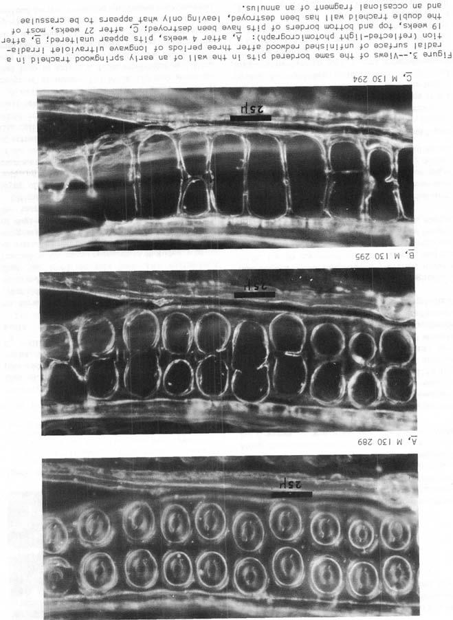
8 A longitudinal microditch consists of a longitudinal microcheck below a longitudinal radiation microditch. In specimens irradiated without in the laboratory, longitudinal radiation microditches occurred alone and in combination with longitudinal microchecks, but the longitudinal microchecks were always seen in combination with a longitudinal radiation microditch. These longitudinal voids are diagramed in figure 2. Diagonal Microchecks A diagonal microcheck is a check that is microscopic in bath length and cross section and appears to follow the angle in the S layer of a tracheid wall. 2 Comparison of Species In this research the redwood specimens were observed in more detail than those of Douglas-fir. Generally, the visible changes in the two species were similar, but they occurred at a faster rate in redwood. This comparative rate agrees with Kalnins studies of the volatile degradation products from these two species during longwave ultraviolet irradiation in air (15). These results are further supported by some earlier work by L. Browne the Forest Products Laboratory. In Browne s determinations, as reported by Kalnins (15), the combined total reduction of cellulose and lignin in the gray layer of naturally weathered wood was greater for redwood than for Douglas-fir. laboratory observations and photomicrographs in the sections will be largely for redwood, However, the few conspicuous differences observed in the behavior of redwood and Douglas-fir will be included. Effect of Longwave Unfinished Radial Surfaces of Springwood Ultraviolet The first apparent changes in the anatomy of radial surfaces of redwood, and eventually the most conspicuous, occurred at the bordered pits in the radial walls of early springwood tracheids. After 4 weeks of longwave irradiation, short, hairline, diagonal microchecks were seen occasionally in the top border (dome-shaped wall over the pit chamber) of pits. The angle of the microchecks suggested that they followed the microfibrils of the S 2 layer of the wall. Otherwise, the pits appeared unaltered (fig, 3A). The microchecks were not much larger after 9 weeks of irradiation. although they were seen in both top and bottom borders of pits in early springwood. After about 10 weeks, apertures (round holes) in the top borders of the pits began a gradual and smooth-edged enlargement, followed enlargement of the apertures in the bottom borders of the pits. The apertures in of pits (fig. 3A) were enlarged to the approximate limits of the pit chambers after 19 weeks of irradiation (fig, 3B). The springwood tracheid walls containing closely spaced bordered pits varied greatly in appearance after 27 weeks, and the area of figure 3B was reduced to narrow transverse strands of wood substance (fig. 3C). These strands, believed to be the crassulae (thickenings in the middle lamella the edges of the pit fields), appeared to be extremely resistant to photodegradation. In the areas of most severe changes, even the crassulae were destroyed at this time with no remains visible when viewed at 625 diameters. In the next layer of radial tracheid walls beneath the crassulae of figure 3C, not visible in the figure, the apertures of the pits were opened to about three-fourths of the size of the pit chambers. In contrast to redwood, crassulae were not seen in Douglas-fir during irradiation. They may have been absent, but if present, they were no more resistant to photodegradation than the surrounding wall areas. The resistance of the spiral thickenings in Douglas-fir did not appear to be much different from the resistance of the walls on they occurred. Narrow rings, consisting of that portion of a border most distant from the aperture of bordered pits and probably including the pit annulus, appeared to be the most resistant portion of radial walls in early springwood tracheids of Douglas-fir. In general, no holes similar to enlargement of pit apertures developed in areas without pits in FPL 6
9

10 in the shielded surface after 26 weeks in the test, Clearly, the longwave ultraviolet radiation caused severe photodegradation of the unshielded wood surfaces. Unfinished Radial Surfaces of Summerwood Figure 4.--Two early springwood tracheids in a radial surface of unfinished redwood after 27 weeks of longwave ultraviolet irradiation. The borders of all pits have been destroyed, but no holes have developed where there are no pits. (Reflected-light photomicrograph.) M redwood springwood tracheid walls by 27 weeks (fig. 4). A few springwood tracheid walls without pits had split longitudinally, however, and these splits, which did not follow the fibril angle of the S wall layer, embrittlement of 2 walls. The simple pits between ray cells and the halfbordered pits between ray cells and springwood tracheids in the radial surfaces of redwood also enlarged, but apparently at a little slower rate than the bordered pits between springwood tracheids. Chemical research on photodegradation of extracted and unextracted wood by Kalnins (15) suggests that this visible difference in the rate of degradation was due to offered by the extractives in the lumens ray cells. Ultimately, all radial walls in the surface layer of early springwood cells were destroyed with no visible remains when viewed at 625 diameters. At this stage, the only visible evidence of the original springwood surfaces were globules of extractives and the vertically oriented tangential cell walls. Some of the tangential walls were tilted or had failed in tension and deflected from their original position. A radial-surface specimen of redwood, with a cover of aluminum foil about 1/8 inch above its test face to shield it from ultraviolet radiation, was placed in the test chamber for comparison with the irradiated surfaces. Its surface temperature was about 10 F. lower than the unshielded specimens. None of the anatomical changes described for the irradiated specimens was observed Longitudinal voids.--the most obvious evidence of change in the summerwood in radial surfaces of redwood during longwave irradiation occurred along the zones of the compound middle lamellas of adjacent tracheids. Slight change in appearance along these zones was first recorded at 4 weeks. By 6 weeks, it was clear that longitudinal voids were developing. The first was that photodegradation was occurring in the compound middle lamellas- zones high in lignin content (13)--andproducing shallow longitudinal radiation microditches (fig, 2). Frequently there were diagonal strands of wood substance In the longitudinal voids, less pronounced, but similar to the diagonal strands observed earlier between summerwood tracheids in weathered surfaces (7). This indicated transverse tensile stresses had caused longitudinal microchecks. These longitudinal microditches (longitudinal microcheck below longitudinal radiation microditch, fig. 2) continued to widen slowly, and the diagonal strands of wood substance became thinner and less conspicuous. After 29 weeks of irradiation, only occasional strands were still visible with reflected light (fig. 5A). Wardrop and Addo-Ashong (17) reported that, when softwoods are subjected to transverse compression, longitudinal compression, or longitudinal tension, strain to failure usually occurs between the S and S layers of tracheid walls. 1 2 There fa a major change in fibril angle and lignin content in this zone, indicating it to be a logical place for stress concentration and strain to failure. Thus, it appears likely that some of the shreds of wood substance observed in the longitudinal microditches included the compound middle lamellas and the S layers of the secondary 1 tracheid walls. To gain a better understanding of longitudinal microditches, the natural. fluorescence of the area of figure 5A was also examined and photographed after 29 weeks (fig. 5B). Color slides of 5A and FPL 74 8

11 Figure 5.--Longitudinal microditches between summerwood tracheids in a radial surface of unfinished redwood after 29 weeks of longwave ultraviolet irradiation: A, reflected-light photomicrograph showing the microditches in the plane of the microtome-cut where they are widest; and B, fluorescence photomicrograph of the same area with deeper focus into the microditches showing the microchecks. 5B were projected separately on a the widths of the five longitudinal microditches were measured in the transverse direction along the same path at about midheight on both slides where the wood surface is continuous except for the microditches. The average width of the microditches was microns on the slide of fluorescence (fig. 5B) and 5.7 microns on the slide with reflected light (fig. 5A). With reflected light, only the radial surface of the wood in the plane of the microtome cut and the maximum width of the microditches at the same level could be observed in good focus. It was possible, however, to focus deeper into microditches when observing fluorescence. After observing many microditches by both reflectedlight fluorescence microscopy, it was concluded that in transverse profile their sides had relatively shallow slopes near the surface that changed abruptly to nearly vertical slopes at the maximum depth of focus with fluorescence (diagramed in fig. 2). This accounted for the differences in width obtained with the two methods of illumination. It was hypothesized that the upper zone of shallow sloping sides due to relatively deep photodegradation wood substance in the highlignin zone of the compound middle lamella. It 9
12 was further hypothesized that the diagonal strands of wood substance and the steep sides of the microchecks in the lower zone were caused by shrinkage stresses in the transverse direction The shrinkage was probably due largely to loss of wood substance by photodegradation over the full width of the radial walls that flanked the microditches in the plane of the microtomed surface. Because it was estimated that moisture content was reduced by only about 3 percent during longwave irradiation, it was reasoned that shrinkage due to loss of moisture had only a minor effect in producing the longitudinal microchecks. The mechanism by which loss of wood substance could produce the required shrinkage stresses was not However, it was speculated that, during photochemical change from solid wood substance to gaseous products, intermediate products are formed that are sufficiently plastic to permit reorientation and drawing together of the residual wood substance by hydrogen bonding or some other attracting forces. The of the two components of the longitudinal microditches in figure 5, and the hypothesis regarding their formation, indicate that a theoretical coating offering no resistance to deformation and remaining bonded to bath top edges of the microditches would have been elongated about percent in the transverse direction at the time figure 5 was taken. In this equation, the numbers in the fraction are dimensions in microns: 3.0 microns is the width of the microcheck in the lower portion of microditch (elongation of the theoretical coating); 5.7 microns is the width between the top edges of the microditch (span of the theoretical coating after elongation); 5.7 minus 3.0, or 2.7 microns, would be the width between the top edges of the microditch if the microcheck was closed (span of the theoretical coating before elongation). The microns is that portion of the width of the longitudinal microditch to be caused largely by photodegradation inthe compound middle lamella (longitudinal radiation microditch). It can be seen that the microchecks between tracheids are narrowest near the bottom of figure where there are no radial walls. Microscopic examination of the specimen at the time the photomicrograph was taken revealed that the microchecks ended a few microns below the bottom edge of figure 5B, but that the radiation microditches did not. supporting the hypothesis their formation. Measurements taken from early photomicrographs showed that the transverse edges of the radial tracheid walls were about even with the bottom edge of figure before visible loss of wood substance occurred; thus the radial walls could easily impose stresses on the middle lamella zones near the bottom of the figure. In this condition, the microchecks should logically extend a little beyond the bottom edge of the photomicrograph. Measuring cell walls and radiation microditches.--during longwave irradiation, measurements were made at a magnification of 480 diameters with a micrometer eyepiece and reflected visible light along a transverse line on a radial summerwood surface of redwood. The line was about 75 microns below and parallel to the bottom edge of figure 5A. The microtome knife had opened the tracheid lumens along the line of measurement, and adjacent pairs of gential walls projected upward. The transverse profile of the surface before irradiation was similar to that of the cutting edge of a saw with evenly spaced teeth worn flat at their cutting surfaces. measurements included the total radial span of six adjacent summerwood tracheids with two flanking tangential walls the radial thickness of each of the seven pairs of adjacent tangential walls in the span. These measurements were recorded at 0, 2.7, 6, 19, 29, and weeks of irradiation. In addition, the surface widths of the longitudinal radiation microditches between adjacent tangential walls were measured after 36 weeks. measurements are recorded in table 2. Figure 6 shows the appearance of five of the seven pairs of adjacent tangential tracheid walls after 36 weeks of longwave ultraviolet irradiation. Table 2 shows that the reduction in the initial total span of microns was 1.5 percent after 2.7 weeks of irradiation and 2.9 percent after 36 weeks. It was reported that the initial moisture content of the wood blocks (about 6 percent) was expected to decrease to between 1 and 2 percent in the early stages of irradiation, and then increase Eo about 3 percent after 4 weeks because FPL 74 10

13 Table 2.--Measurements on a radial surface of unfinished redwood across seven double tangential walls of early summerwood tracheids during longwave irradiation 1 the radiator was placed in air at a higher relative humidity. Based on Browne s data for radial swelling of bands of summerwood attached to springwood in redwood surfaces (2), it appears that the reduction in total surface span during the first 2.7 weeks was probably due primarily to shrinkage caused by loss of moisture from the block, The appearance of the double walls (fig. 6) and Figure 6.--LongitudinaI radiation microditches between five pairs of adjacent tangential tracheid walls in a radial surface of unfinished redwood summerwood after 36 weeks of longwave ultraviolet irradiation. (Reflected-light photomicrograph.) M the data on reduction in their thickness in table 2 indicate that the reduction in total span from 203 to microns between and weeks was due largely to loss of woad substance by photodegradation at the two edges between which total span was measured. Regardless of the cause, the reduction of 2.9 percent in the total span, which occurred at a slow rate, is too small to be the most serious threat to the integrity of a coating on a wood surface. Data in table 2 show that during 36 weeks longwave irradiation, the average radial thickness of seven consecutive of adjacent tangential summerwood walls changed from 12.4 microns to 9.2 microns, a reduction of about 25 percent. These measurements were made from lumen to lumen across double walls without subtracting the width of the radiation microditches that formed the intervening span. The final average width of the radiation microditches was 3.0 microns--another loss of about 25 percent of wood surface from the original span of 12.4 microns. Thus, the total loss of wood Surface was about 50 percent the remaining portion of each original double wall surface was in two strips of about equal width. 11
14 With reflected light, it appeared that the strips of wood surface in figure 6 had rounded rather than square edges after irradiation. This appearance and the measurements of wall thickness indicated that photodegradation occurred at about equal rates on the lumen and middle lamella edges the tangential walls, Sachs (12, 13) reported that lignin was more concentrated in the compound middle lamella, S layer, and warty layer than in the intervening 3 thick S 2 layer of the cell wall. The same distribution of lignin has also been reported in studies of wood heavily attacked by brown-rot fungi that destroy the cellulose (4). This suggests that the apparent rounding and loss of wood substance at both edges of the tangential walls during longwave irradiation caused by the lignin degrading faster than cellulose. The natural fluorescence of the area of figure 6 was observed at a magnification of diameters after 36 weeks of irradiation to obtain additional information on the formation of longitudinal voids in the zones of the compound middle lamellas. Longitudinal microchecks could not be Seen clearly in these longitudinal voids that were not flanked by radial walls. This indicated that the 3.0-micron average width of the voids (table 2) was due largely to photodegradation in the voids (longitudinal radiation microditches) rather than to microchecking. This width of 3.0 microns was similar to the 2.7 microns of width reported due to photodegradation in longitudinal microditches after 29 weeks when radial walls flanked the ditches (fig. 5). The similar widths believed due to photodegradation in the longitudinal voids in the areas (figs. 5 and 6) and the absence of clearly visible microchecks when radial walls did not flank the longitudinal voids (fig. 6) are additional evidence to support Me hypothesis for the formation of the longitudinal voids. Adhesion Regardless of the validity of the hypothesis for formation of longitudinal voids, the reduction in tracheid wall thickness in table 2 leaves little doubt that considerable summerwood substance was destroyed by the longwave irradiation, Similar changes in summerwood surfaces under a clear coating would seriously weaken or destroy the specific adhesion and place a greater burden on the mechanical grip of the coating. Nearn (10) reported that, under certain conditions, alkaline phenol-formaldehyde glues penetrate wood cell walls to form an interface in depth, He also reported there was evidence that one does not obtain consistently good results under severe service conditions, unless this type of interface is formed. He stated, however, that as far as is known, the general run of coating materials do not penetrate the cell wall to form interfaces in depth with wood. Dr. van Loon, in a report on microscopic studies of the penetration of coatings containing fluorescent dyes (16), stated that paint materials do not sink into the wood cell walls where the bound water is found. It thus appears that the mechanical grip of a coating on wood depends on penetration into pits, microchecks, and open lumens, and envelopment of cell-wall fragments at the surface. Unfinished Surfaces Tangential Bordered pits occur in the tangential walls of longitudinal tracheids of coniferous woods except for a few of the pines. The southern pines (Pinus sp.) and ponderosa pine (Pinus ponderosa Laws), commonly used for exterior surfaces, are without such pitting. When present, the bordered pits are confined to last few rows of summerwood tracheids and the inner tangential wall of the first-formed springwoad tracheids of the succeeding year. The only other pits in tangential walls of coniferous tracheids are half-bordered pits between tracheids and the infrequently occurring longitudinal parenchyma cells (1). The most obvious and consistent anatomical changes produced by longwave ultraviolet irradiation in tangential surfaces of redwood were diagonal microchecking through bordered pits in walls of tracheids and loss of ray cell walls. The checks appeared to follow the fibril angle of the S wall layers. 2 Springwood-over-summerwood and summerwood surfaces.--after 7 weeks of longwave irradiation, microchecks at bordered pits in tracheid walls were numerous. They were hairline checks where the surface layer of wood consisted FPL 74 12


15 of two tangential walls, one above the other and joined by a common middle lamella. When a springwood wall was over a summerwood wall, the checks were usually present only in the summerwood. When the surface layer consisted of two summerwood walls, the checks were quently seen in both walls. Occasionally, the microtome knife cut along the approximate plane of the compound middle lamella between tangential cell walls, leading a single summerwood wall at surface, The of these single walls was greatly influenced by pits. When pits were not present, diagonal microchecks were not common at 7 weeks. When they were present, wide diagonal microchecks extending through the pit apertures were common (fig. 7). After 13 weeks of irradiation, the microchecks in the double-wall surfaces consisting of springwood over summerwood were still closed (fig. 8), whereas those in the single summerwood wall of figure 7 averaged 9.7 microns at their widest This was about percent greater than their average maximum width of 6.4 microns at 7 weeks. When the area of figure was examined after 37 weeks, the single summerwood wall was almost completely destroyed and the double wall in Me next layer of wood beneath it was fully exposed to the radiation. The condition of other single- and double-wall surfaces similar to figures 7 and 8 varied considerably at this time, indicating variability in influence of factors such as amount of extractives, frequency of pits, thickness of tangential walls (natural variation or variation due to depth of cut within the tangential walls), and partial shielding from radiation by the radial walls projecting vertically above the tangential walls. Figure 7.--Diagonal microchecks through bordered pits in a single summerwood tracheid wall in a tangential surface of unfinished redwood after 7 weeks of longwave ultraviolet irradiation. (Reflected-light photomicrograph.) M Figure 9.--Typical appearance of two types of tangential surfaces with bordered pits in unfinished redwood after 37 weeks of longwave ultraviolet irradiation. Upper: Single summerwood tracheid wall. Lower: Double wall of springwood over summerwood. (Fluorescence photomicrograph.) M Figure 8.--Diagonal microchecks through bordered pits in double tracheid walls (springwood over summerwood) in a tangential surface of unfinished redwood after 13 weeks of Iongwave uitraviolet irradiation. The microchecks are in the summerwood walls. (Reflected-light photomicrograph.) M Figure 9 shows the typical appearance, after 37 weeks of longwave ultraviolet irradiation, the types of wood surfaces containing pits-- a single summerwood tracheid wall and a double wall consisting of springwood over summerwood. Hairline microchecks developed early in the general direction of the fibril angle of the S 2 layer in the summerwood walls of both types of surfaces. The microchecks the single summerwood wall enlarged gradually and produced more void 13

16 space than the remaining area of wood substance in the wall by 37 weeks. In contrast, widening of the microchecks in the summerwood tracheid wall under the springwood wall was delayed many weeks. Ultimately, the thin springwood wall failed along lines of the microchecks in the summerwood wall, and the checks had widened a moderate amount by 37 weeks. Double-wall surfaces at summerwood.--when the surface layer consisted of two summerwood walls containing pits, the hairline microchecks through the pits opened with great reluctance. The top-wall microchecks eventually opened moderately, and the two walls appeared to separate in the plane of the middle lamella, permitting the checks in bottom wall to open. This microchecking was not as general or as advanced as the checking at pits in springwood over summerwood walls after 37 weeks of longwave irradiation. At this time, when pits were absent, microchecks were rare in double tangential walls of summerwood. The pits were obvious points of stress (stress raisers). The observations on checking at bordered pits in tangential surfaces indicate that, for species with tangential pitting, coatings on flat-grained lapproximately tangential) boards will not weather as well the edges of the broad summerwood bands where pits in tracheids are concentrated as over the remaining summerwood where the tangential walls have no pits. Compression wood surfaces.--the restraining action of one summerwood wall on another was demonstrated best by the redwood specimens of compression wood. In this abnormal wood, numerous spiral (diagonal) microchecks that follow the fibril angle of the S layers of 2 summerwood tracheids are present in the living tree. Many of these checks are so fine that they cannot be seen with a light microscope (3, 18). They were stress raisers and opened readily during irradiation. Figure reveals a compression wood surface of summerwood having single and double tangential tracheid walls without pits, after 27 weeks of longwave irradiation. The microchecks in the single walls have opened wide in contrast to single walls of normal redwood without pits after 27 weeks. Each wall checking of the other in the double-wall surface because the alternated fibril angle of their S layers, 2 Figure 10.--Tangential summerwood surface of unfinished redwood compression wood after 27 weeks of longwave ultraviolet Double tracheid walls with diagonal microchecks in both walis are shown at upper left and lower right, and single tracheid walls in the other two quadrants. Ray cells have been destroyed in The ray at left center. (Fluorescence photomicrograph.) M As a result, the microchecks in the bottom wall are still relatively tight and those in the top wall are narrower than in the single walls. The microchecks in the bottom walls did not. open widely until the top walls were severely degraded or the bond between the two walls failed. In contrast to normal wood, the many cones of weakness in tracheids of compression wood indicate that distribution of pits in the bands of summerwood on flat-grained siding surfaces is of little consequence in determining performance of coatings on these dense bands of the abnormal wood, Degradation of ray cells.--a tangential surface of wood exposes the cross section of the thinwalled cells in the rays. That such cells were readily degraded by longwave irradiation is illustrated by their absence from the ray in the tangential surface in figure 10. Some ray cells were partially destroyed to a depth of 45 microns. The layer of extractives lining the lumen of some of the ray cells in redwood was more resistant to photodegradation than the cell wall. Occasionally, the thicker layers of extractives remained intact and careful examination was required to reveal that the cell walls were destroyed at surface, leaving hollow columns of extractives that resembled ray cells. Springwood tracheid walls versus cell walls.--the tangential surfaces of redwood consisting of double walls of springwood tracheids had no pits; these surfaces were very resistant to the formation of round holes or splits. In this they were similar to the areas with no pits in springwood tracheids on radial walls. After FPL 74 14

17 11 weeks of irradiation, families of short, hairline diagonal microchecks were occasionally seen in the tangential walls of springwood tracheids. They were a little more plentiful by 30 weeks, they were rarely more than slightly opened. Pits are present in double tangential wall surfaces of springwood consisting of a tracheid and a longitudinal parenchyma cell. Surfaces of this type, occurring infrequently, were considerably less durable than those consisting of two walls of the unpitted springwood tracheids. These results indicate again that pits play a role in the deterioration of springwood walls. The condition of these two types of tangential springwood surfaces after 30 weeks of irradiation is illustrated in figure 11. Figure 11.--Relative deterioration of two types of double springwood cell walls in the tangential surface of unfinished redwood after 30 weeks of longwave ultraviolet irradiation. Upper: over tracheid showing almost complete loss of cell walls. Lower: Tracheid over tracheid with no visible deterioration. (Fluorescence photomicrograph.) M The first conspicuous evidence that the tangential walls of springwood tracheids were being destroyed was an occasional microcheck in the longitudinal direction with no conspicuous Influence of the fibril angles in the S 2 layers. This suggested that the walls were embrittled during irradiation. Usually such checks started at transverse edges formed where the microtome knife intersected cut through tangential walls to expose a new lumen. These edges in the thin sheets of wood substance were logical stress raisers. Effect of Beat Without Ultraviolet Irradiation A redwood specimen with its tangential test surface shielded from radiation by a ventilated cover of aluminum foil was placed the test chamber for comparison with the irradiated tangential surfaces. The temperature of the shielded surface was about equal to that of the irradiated surfaces (132 F.). After 24 weeks of heating in the irradiation chamber, mild anatomical changes resembling the early stages of deterioration of the irradiated surfaces were seen the shielded surfaces, The changes were numerous hairline diagonal microchecks through pits in double walls and an occasional diagonal microcheck, moderately opened, through pits in single summerwood walls. The edges of these open microchecks appeared sharp rather than rounded. The cross sections of the ray cells appeared unaltered. The most conspicuous change in the shielded surface was the occurrence of numerous tiny fragments of wood, usually strips but sheets, that appeased slightly shrunken and curled away from the summerwood mass. A similar change was not observed in the unshielded specimens. If the fragments occurred, they were destroyed by photodegradation before they were large enough to be seen when magnified 400 diameters. The quality of the microtome cut may also have been a factor; poor quality cuts loosen more fragments than do cuts of good quality. Nearn (10) showed that the surface of commercially cut Douglas-fir veneer has many tiny wood fragments that appear only partially attached. They are similar to the fragments observed in the heated but unirradiated specimen. In earlier research on slow pyrolysis of wood at the Forest Products Laboratory, small samples of ponderosa pine. surfaced with a fine-tooth saw were heated in an oven for about weeks at 212 and 302 Examination of the relatively rough surfaces revealed that the specimen heated at 302 F. had a few shrunken or curled fragments of wood similar to those on the specimen shielded from irradiation, In addition, there were many hairline diagonal microchecks. The final weight loss was 4.5 percent of the original ovendry weight of the woo4 No abnormalities could be seen in the surface of a specimen heated at 212 F. that had a final weight loss of 1.6 percent. 15

18 It was concluded that the changes seen in the tangential surfaces of wood irradiated with ultraviolet were due largely to loss of wood substance by photodegradation rather than by thermal degradation. Varnished Wood The varnished wood surfaces exposed to the longwave irradiation were polyurethane varnish on a radial surface of redwood and phenolic varnish an four wood surfaces: a radial and a tangential surface of redwood, a radial surface of compression wood of redwood, and a tangential surface of Douglas-fir (table 1). The unfinished redwood and Douglas-fir fluoresced brightly when irradiated with ultraviolet under the microscope, and details of the surface anatomy could be seen clearly, even at the highest magnifications used. In contrast, fluorescence of the wood under both varnishes was weak, although it was a little brighter under the phenolic varnish, Useful microscopic observations of wood under both varnishes could be made at the higher only with reflected light. The weak fluorescence indicated that the varnishes were preventing a large proportion of the ultraviolet radiation from reaching the wood. If the changes reported for unfinished wood were due primarily to ultraviolet radiation, then there should be considerably less change in the wood under the varnishes during the same exposure period. Microchecks in wood surface.--after 10 weeks of irradiation, tight diagonal microchecks were seen occasionally in springwood tracheids in radial surfaces of redwood under the phenolic varnish. During the last detailed inspection of the wood surface at 36 weeks, these checks were very numerous but still closed, and the summerwood appeased unaltered. At this time, the diagonal microchecks of the redwood compression wood also appeared closed under the phenolic varnish. Figure 12 shows typical checking in redwood springwood at the wood-phenolic varnish interface after 30 weeks of longwave irradiation. Similar checks occurred less frequently in redwood under the polyurethane varnish, suggesting that it gave slightly better protection because it absorbed more ultraviolet than did the phenolic varnish. Figure 12.--Microchecks in a radial springwood surface of redwood at interface of wood and phenolic varnish after 30 weeks of longwave ultraviolet irradiation. (Reflected-light photomicrograph.) M 130 contrast to unfinished springwood, the microchecks in the varnished springwood did not often pass through bordered pits. The microchecks occurred most frequently in the wall of a surface tracheid straddling the line formed by the intersection of the underside of that wall with the top corners of two adjacent tracheids below. This location, similar to the intersection of the bottom side of a metal canoe and its keel, is illustrated by the family of diagonal microchecks in figure 12. It is a logical place far stress concentration because of differential stresses in the coating and in the three walls of adjacent tracheids involved. Minor diagonal microchecks at bordered pits in summerwood were the only changes seen in tangential surfaces of redwood and Douglas-fir under phenolic varnish during 36 weeks of longwave ultraviolet irradiation. Degradation of varnish surface.--although both varnishes gave the wood excellent protection from longwave ultraviolet radiation, the varnishes deteriorated slowly. The polyurethane varnish appeared to give slightly better protection to the wood, although it suffered most during the tests. By 32 weeks, this varnish had lost gloss and become slightly milky in appearance over about 25 percent of its area. Microscopic examination of the flat area revealed that the change was due to intricate patterns of closely spaced microchecks in the varnish (fig. 13) or to an eroded appearance that suggested preferential photodegradation of some of the ingredients in the varnish. No loss of gloss was apparent in the phenolic varnish after 36 weeks FPL 74 16
 Figure 14.--Transverse section of Douglasfir.")
 M 130 931 M 130 305 in the test, and its surface was not in the way described for the polyurethane.")


19 Figure 13.--Microchecks (crazing) in the surface of a polyurethane varnish over redwood after 32 weeks of longwave ultraviolet irradiation. The microchecks reduced the gloss of the varnish. (RefIected-light photomicrograph.) Figure 14.--Transverse section of Douglasfir. The top edge shows the profile of a radial surface with lumens open and double tangential walls of springwood and summerwood tracheids projecting vertically above the radial walls. (Fluorescence photomicrograph.) M M in the test, and its surface was not in the way described for the polyurethane. A few widely spaced, straight or curved surface checks developed in the phenolic varnish over Douglas-fir but not over redwood or compression wood of redwood. The checks could be seen easily with a 14-power hand lens. Although average thicknesses of the varnishes were not obtained in this study, it was obvious that the phenolic varnish considerably thicker on the Douglas-fir, suggesting that the coarse checks were related to thickness of coating. Vertically projecting cell walls in wood surface.--double tangential walls of springwood and summerwood tracheids frequently project vertically above the radial walls in microtomed, hand-planed, or carefully machine-planed radial wood surfaces. This type of projecting in microtomed surfaces is illustrated in transverse profile in figure 14 and in radial view in figure 15. Such vertically projecting walls produce parallel lines of thinness (stress raisers) in a coating. Although the reduction in varnish thickness over these projecting walls was not measured, the maximum reduction would be equal to the diameter of tracheid lumens. Thus, the maximum reduction over springwood, between 2 and 3 mils (50 and 75 microns) on redwood surfaces, would be greater than over summerwood. On radial surfaces redwood, both varnishes checked along their lines of thinness over vertically projecting walls of springwood but of summerwood. This microchecking was first ob- Figure 15.--Microtomed radial surface of redwood looking into open lumens between vertically projecting double tangential tracheid walls. Open lumens dip below the surface under a ray at the left. (Fluorescence photomicrograph.) M Figure 16.--Phenolic varnish on a radial springwood surface of redwood similar to the upper half of figure 15 after 1 year of longwave ultraviolet irradiation. The varnish has checked on its lines of thinness over the vertically tangential walls. (Fluorescence photomicrograph.) M
 were seen frequently in both varnishes Over radial surfaces of redwood springwood. Only the phenolic varnish was tested over tangential surfaces of redwood and Douglas-fir.")
20 served after 32 weeks of irradiation of the phenolic varnish on a radial surface of redwood. After 1 year of longwave ultraviolet irradiation, microchecks of this type (fig. 16) were seen frequently in both varnishes Over radial surfaces of redwood springwood. Only the phenolic varnish was tested over tangential surfaces of redwood and Douglas-fir. On these surfaces, the varnish appeared thicker, and microchecking of the varnish over the vertically projecting springwood walls was rare, indicating the importance of an adequate film thickness. During examination after 1 year of longwave irradiation, the microchecks in the thin varnish usually appeared to extend into the pairs of vertical walls rather than along the wood-varnish interface on the lumen side of a vertical wall. This indicated that the varnish was still well bonded to the vertical wood surfaces. Because longitudinal microchecks did not occur between vertically projecting pairs of springwood walls of unfinished wood during irradiation, it was concluded that transverse s h r ink age stresses in the varnish caused the microchecks of this type in the varnished springwood. Reduction in varnish thickness.--all varnishes appeared to be thinner after 1 year of irradiation. On radial surfaces of redwood, the upper edges of the vertically oriented springwood tracheid walls were occasionally in the plane of the varnish surface. These exposed wood surfaces usually did not appear to be degraded, indicating that they had been protected by varnish during a considerable of the irradiation period. In addition, numerous microsized hills, ridges, and plateaus of my sizes and shapes were seen in the originally smooth surfaces of both varnishes (fig, 17). These projections, more numerous in the polyurethane varnish surface than in the phenolic, appeared to be minor ingredients of the varnishes that were highly resistant to photodegradation. The range in thickness of the more conspicuous projections was 4 to 6 microns in the phenolic surface and 6 to 11 microns in the polyurethane. It was concluded that the varnishes were being reduced in thickness by photodegradation while they were protecting wood from irradiation, and that the reduction was at least equal to and probably greater than the maximum thickness of the surface projections. Figure 17.--PoIyurethane varnish surface after 1 year of longwave ultraviolet irradiation showing particles of varnish resistant to photodegradation. The surface of the large plateau is 10 microns above the surrounding surface. (Fluorescence photomicrograph.) M Clear Overlays on Wood Overlaid specimens exposed to longwave irradiation were those with vinylidene-fluoride film over radial and tangential surfaces of redwood and a radial surface of Douglas-fir and one with polyvinyl-fluoride film over a radial surface of redwood (table 1). These overlays were not to the wood surface but were held in place with cellophane tape. The wood surfaces under both film fluoresced brightly when irradiated with ultraviolet from the xenon lamp during microscopic examination. This indicated both film were transparent to ultraviolet, and major changes should occur in the wood under the films in the irradiation tests if the changes reported fox unfinished wood were due primarily to ultraviolet radiation. Major changes in the wood surface anatomy did occur under both films the irradiation teats. The changes were similar to those reported for unfinished wood, but were not as marked after equal periods of irradiation. This indicated that the films offered only moderate protection to the wood. Possible reasons for protection are the ability the films to absorb or reflect some ultraviolet and to limit the supply of oxygen at the wood surface. Kalnins (15) reported on the effects of oxygen on the rate of photodegradation of wood. Figure 18 shows the appearance of bordered FPL 74 18

21 Figure 18.--Bordered pits in a double wall of early springwood tracheids in a radial surface of redwood under an unbonded of clear vinylidene-fluoride resin after 32 weeks of longwave ultraviolet irradiation. (Reflected-light photomicrograph.) M pits in a radial springwood surface of redwood under the vinylidene-fluoride film after 32 weeks of irradiation. The degradation in this area was worse than average for the springwood, but still occurred commonly. An approximation of the protection offered by the films can be obtained by comparing figure 18 with the unfinished surfaces in 3C and 4 taken after 27 weeks of irradiation. It was concluded that there was little difference in protection offered by the two films. No obvious visible changes occurred in the two films during longwave irradiation. Both film were folded and creased with no evidence of embrittlement after 43 weeks in the test chamber. Embrittlement of Wood Surface Slight pressure was applied unintentionally on the test face with a scalpel when overlay was removed from a radial surface of redwood at 32 weeks. Microscopic examination revealed that the springwood tracheid walls had failed in a brittle manner under the load. Similar failure was also observed in springwood at the edges of both radial and tangential redwood surfaces under the overlays. The failure was presumed due to forces applied in pulling the overlay over the test face during a previous replacement. To gain more information on the embrittlement, three unfinished redwood specimens-- one unirradiated, one heavily irradiated, exposed in the radiation chamber but from radiation--were scratched with a and then examined microscopically. The irradiated springwood tracheid walls and one shielded needle heavily broke readily into irregularly shaped platelets with only a moderate amount of diagonal microchecking near the scratch. Springwood surfaces of the other specimens also failed under the needle, irregular platelets of the cell wall were considerably fewer and there were many diagonal microchecks near the scratches. The springwood of the shielded specimen appeared to be in a midposition; was obviously more brittle than the unirradiated springwood but not nearly so brittle as after irradiation No decision was reached on the brittleness of the summerwood with this simple test. Earlier research (6) showed that severe crushing of springwood tracheids occured when the tangential surface of dry southern pine lumber was surfaced in a dull planer. Much of the distortion was retained until the wood was wetted. Then the springwood cells approximated their original shape, indicating that unirradiated and unheated springwood is not brittle. Silicone Resin on Wood One radial redwood surface coated with the silicone resin was irradiated in the longwave ultraviolet chamber. wood under the coating fluoresced brightly when irradiated with ultraviolet in the microscope, and major changes occurred in its surface during irradiation in the teat chamber. Diagonal microchecks and enlarged apertures.--short, hairline diagonal microchecks were first seen in springwood at about 5 weeks, the same time as they were seen under the vinylidene-fluoride film, and 3 to 7 weeks earlier than in the varnished surfaces. These microchecks under the silicone resin were more numerous and more conspicuous although still closed after 10 weeks. More than half of them avoided the bordered pits. More than of the diagonal microchecks in springwood tracheid walls also avoided the bordered pits under the varnishes but not under the two unbonded overlays or in unfinished wood 19

22 surfaces. The tendency for diagonal microchecks to avoid the bordered pits was more pronounced under the two varnishes than under the Silicone resin. This illustrates that the three wet-applied coatings, particularly the varnishes, altered the stress patterns in the wood surfaces. About 500 bordered pits in springwood tracheids under the silicone resin were examined after 23 weeks of irradiation. Most of them showed enlargement of their apertures; this ranged from slight in late springwood to the full limits of the space between the crassulae in early springwood. This full enlargement is illustrated in figure It was possible to focus the microscope below irradiated surfaces similar to figure 19 and see diagonal microchecks and moderate enlargement of pit apertures in the next layer of radial springwood walls. When compared with unfinished springwood, it appeared that the silicone resin offered little if any protection to the wood (compare fig. 19 with fig. 3B and C). Figure 19.--Bordered pits in a double wall of early springwood tracheids in a radial surface of redwood under a coating of siiicone resin after 23 weeks of longwave ultraviolet irradiation. Top and bottom borders of the double row of pits have been destroyed leaving little more than the crassulae. (Fluorescence photomicrograph.) M After 23 weeks, it was observed that the diagonal microchecks in the springwood were more numerous than at 10 weeks and were often moderately opened. More of them appeared in walls in which bordered pits were scattered or absent than in walls in which pits were closely spaced. Longitudinal voids in wood.--after 23 weeks of longwave irradiation, there were longitudinal microditches along most junctions between adjacent pairs of tracheids in summerwood. Longitudinal microditches under the silicone resin can be seen in figure 20. Figure 20A, a fluorescence photomicrograph, has the microchecks at the lower levels of five microditches in good focus. Figure 20B, a reflected-light photomicrograph of the same area, has only three conspicuous microditches--the same ones in which shreds of wood substance can be seen in figure 20A. It appeared that fragments of wood are important for recognizing the microditches under reflected light and that fluorescence is a useful to reflected light for the microscopic observation of clear-coated wood surfaces. When measured on the projected images of colored slides, the widest microditch (second from bottom in fig. 20B) was 3.8 microns wide at its surface, and the microcheck at its lower level was 2.2 microns wide. These measurements indicate that, if the coating was securely bonded to both edges of the microditch, the elongation of the coating was about percent ( x 100) Although this exceeded considerably the 100 percent maximum elongation reported for the silicone resin, it did not over the microditch. This indicates either the coating had little if any specific adhesion initially, or that photodegradation of a microthin layer of wood surface destroyed specific adhesion of the coating. Thus, the transverse deformation indicated by the microcheck width (2.2 microns) could not cause excessive elongation of the coating over the microditch. Advanced deterioration and embrittlement of wood.--during examination of this specimen at 29 weeks, the longitudinal microditches in summerwood appeared wider, and more of them could be seen through the coating with reflected light. Early springwood tracheids with the degree of degradation illustrated by figure 19 were numerous, and tracheids that had resembled those in figure 19 at 23 weeks were difficult to identify with certainty because the crassulae were reduced in width or completely destroyed. Short, diagonal microchecks were numerous and conspicuous at 29 weeks, particularly in late springwood in which there were also occasional long microchecks that extended generally in the longitudinal direction in the radial walls. These long microchecks, illustrated in figure 21, indicated that the walls had become brittle. Adhesion of coating to wood.--the silicone FPL 74 20

23 Figure 20.--Fluorescence, A, and reflected-light, B, photomicrographs of the same summerwood area in a radial surface of redwood under a coating of siiicone resin after 23 weeks of longwave ultraviolet irradiation. Longitudinal microditches can be seen in the compound middle lamellas between tracheids. A, Only the microcheck portion of each microditch is in good focus. Wood fragments are conspicuous in the second, fourth, and fifth microditches from the top. B, Longitudinal microditches can be seen only in the second, fourth, and fifth compound middle lamellas from the top that have the conspicuous fragments seen with fluorescence in A. resin had its full and maintained its original tangential walls that projected vertically from position over most of the wood surface after the surface. 29 weeks of irradiation The spreader used to At unknown time between 23 and 29 weeks, apply the resin scraped along the wood surface some of the fingers of resin pulled free from near one end, packing the resin into the open the surface lumens in this area where the coatlumens of the surface springwood tracheids ing was thinnest, indicating stresses in the 15); left little if any coating above coating, The fingers of resin were straight or 21
 M 130 288 curled to various degrees, and some were twisted together.")
24 Figure 21.--Late springwood surface of redwood under a coating of silicone resin after 29 weeks of longwave ultraviolet irradiation. Brittle microchecking has occurred in radial tracheid walls with and without bordered pits. (Fluorescence photomicrograph.) M curled to various degrees, and some were twisted together. There were a few fragments of cell wall, attached to the fingers and scattered on the adjacent surface, that indicated brittle failure of the walls and possibly violent action when the resin pulled free from the open lumens. The general appearance of the wood surface after 29 weeks indicated that there could be little if any specific adhesion between the coating and the wood surface; apparently the coating was relying on mechanical adhesion obtained largely from fingers resin that dipped below the surface into open lumens. For any coating applied wet on a wood surface, the maximum number of fingers of the coating material dipping into a given area of surface depends largely on the width and length of the tracheids and the angle of intersection of their long axis with the surface. The number increases with decreasing width and and increasing angle if the method of surfacing the wood does not close the lumens by crushing packing with wood fragments. A cleanly cut radial wood surface will provide more narrower open-lumen anchor points per unit area in summerwood than in springwood (fig. 15). Examination of machine-planed compression wood of redwood that, when a summerwood tracheid presented a wall rather than an open lumen in the plane of the cut, tiny segments flanked by the spiral checks were frequently torn from the wall. Thus, several openings could occur through the surface wall of one tracheid when its long axis was parallel to the plane of the cut. This behavior was not often observed in machine-planed surfaces of normal redwood. It is probable that local deviations of the long axis of surface tracheids could also produce more than one anchor point in a tracheid lumen. After 44 weeks of irradiation, the silicone resin had full gloss, no checks, and was still adhering to the wood except at one end where the coating was very thin. To investigate the nature of this adhesion, the point of a needle was pushed by hand through the coating at a shallow angle and moved along the coating- springwood interface in the transverse direction. When viewed through the microscope, the resin trembled with the needle and deformed readily under the point. As the point pierced the coating and moved forward, coating first rode up on the needle and then split reluctantly. The split preceded the needle across wood. One edge of the coating was peeled back with tweezers, and it appeared that the only adhesion to both springwood and summerwood growth was by means of the fingers of resin that dipped below the surface. Some of the larger fingers that broke at the wood surface during the peeling operation were pulled with tweezers in direction of their long axes. First they elongated with reduction in cross section, and then they slid out of the cell lumens. An unirradiated coating of the silicone resin on wood was probed and pulled in the same way, and it also appeared to have little if any specific adhesion. Its behavior was similar to the irradiated coating in other respects, although it appeared a little more elastic and a little more resistant to splitting in front of the needle. These of the irradiated and unirradiated coatings of silicone resin confirmed the earlier opinion that the irradiated coating was held in place largely by mechanical adhesion. The types of microchecks and loss of wood substance observed under the silicone coating during longwave irradiation also occurred under it during 1 year of weathering. In spite of the changes that occurred in the wood, the silicone coating was still adhering to it after 1 year in both exposures. It thus appears that the more elastic or more plastic clear coatings with lower moduli and higher strain to failure than conventional varnishes should adhere longer to exterior wood FPL 74 22

25 surfaces, A method of preparing wood surfaces for finishing that does not close surface lumens by crushing or filling with wood fragments should favor good mechanical adhesion of such coatings. Effects of Shortwave Ultraviolet Unfinished Wood Surfaces Radial and tangential surfaces of both redwood and redwood compression wood and a radial surface of Douglas-fir were exposed to shortwave ultraviolet radiation (table 1). The visible effects of this shortwave were generally similar to those of the longwave, but they occurred at much faster rates. For example, when bordered pits were abundant in a radial wall of an early springwood tracheid of redwood, 2 weeks in the shortwave test usually reduced the wall to not much more than the craasulae. The appearance at that time was similar to the tracheids in figure 3C, showing longwave irradiation effects after 27 weeks. Although diagonal microchecks in the pit borders in springwood walls were rare during shortwave irradiation, the apertures an oval shape during enlargement to suggest an influence of the fibril angle, By the time the apertures were enlarged to the limits of the pit chambers, the edges of the holes had changed from smooth to scalloped (fig. 22). This was in contrast to the effects of longwave irradiation, after which the edges remained relatively smooth Figure 22.--Radial wall of a springwood tracheid in an unfinished redwood surface after 17 days of shortwave ultraviolet irradiation. Holes have formed in two pit fields without pits (left edge and right center) in the double row of deterioriated bordered pits. (Fluorescence photomicrograph.) M (fig, 4). The last springwood walls degradedwere those without pits just as with longwave irradiation. The first evidence of deterioration from shortwave ultraviolet in the springwood walls without pits was many tiny, irregularly shaped holes in the walls. These holes then enlarged to consume the walls without conspicuous checking. This type of deterioration can be seen at the pit fields without pits in figure 22. This behavior in the absence of pits was not observed during longwave irradiation (fig;. 4) in which long microchecks in the longitudinal direction were the first conspicuous evidence of deterioration of such springwood walls (fig. 21). This and other comparisons of the effects of two wavelengths suggest that photodegradation occurred more preferentially in some constituents of the wood during shortwave irradiation and caused less embrittlement and less transverse shrinkage in springwood walls. Longitudinal microditches and longitudinal radiation microditches occurred in the compound middle lamellas in radial redwood surfaces during shortwave irradiation. However, the diagonal strands of wood substance in the longitudinal microditches were considerably less numerous and less conspicuous than after longwave exposure. Possible reasons for the difference are less transverse shrinkage to form the diagonal strands, thinner strands because of fewer layers of wall attached to the middle lamella, or the more rapid deterioration of the strands during the shortwave tests. On the tangential surface of redwood, open diagonal microchecks bordered pits were common by 9 days of shortwave irradiation, The influence of single and double summerwood walls and a springwood over a summerwood wall was similar to that described fer longwave tests. In shortwave irradiation, however, the edges of the wider microchecks were usually scalloped rather than smooth. This suggested that compared to longwave irradiation, the of diagonal microchecks during the shortwave tests was due more to degradation at the edges of the checks and less to shrinkage caused by degradation in the wall between checks. Clear-Coated Wood Phenolic varnish and vinylidene-fluoride film on radial surfaces of redwood and phenolic 23

26 varnish on a tangential surface of redwood compression wood were exposed to the shortwave irradiation (table 1). The phenolic varnish gave the wood excellent protection until the varnish was severely deteriorated. The varnish had lost all gloss after 2 weeks of irradiation and it was difficult to see the wood structure under it, even at low magnifications, However, the wood appeared unaltered. The varnish surface had a marked pebbled appearance after 3 weeks, but the springwood surface could still be seen with difficulty in a few isolated and it appeared normal. The varnish surface became progressively rougher and eroded in appearance; after 9 weeks the coating almost completely destroyed and was no longer protecting the wood surface. Figure 23, illustrating this condition, reveals resistant particles of the varnish crassulae that flank void spaces formerly occupied by bordered pita in surface springwood tracheids. chamber for 4 weeks. At the end of the test period, the vinylidene-fluoride film appeared slightly milky, and the polyvinyl-fluoride film had yellowed moderately. No deterioration visible microscope occurred in the surface of either film The vinylidene-fluoride film could be folded over on itself and creased with no failure, the polyvinyl-fluoride film broke in a brittle manner when bent moderately. Shortwave versus Longwave Ultraviolet It appears from the comparisons in this research that shortwave ultraviolet irradiation is a useful, accelerated method for predicting the microscopically visible effects of longwave ultraviolet irradiation unfinished wood. Unfortunately, when clear-coated wood was irradiated, shortwave irradiation was unreliable for predicting the effects of longwave irradiation on the coating and the wood. Longwave Ultraviolet with Wetting Figure 23.--Phenolic varnish on a radial surface of redwood after 9 weeks of shortwave ultraviolet irradiation. Varnish and wood are severely degraded. Voids previously occupied by bordered pits can be seen between crassulae in springwood tracheids, (Reflected-Iight photomicrograph.) M In contrast to the severe effects of 9 weeks of shortwave irradiation, 9 weeks of longwave irradiation caused no microscopically visible changes in the phenolic varnish or the wood under it except for a few hairline diagonal microchecks that occurred in walls of springwood tracheids. The degradation of wood under the vinylidenefluoride film during shortwave irradiation was similar to that of the unfinished wood although the rate was slower. In a separate experiment, a strip of each of the two film was irradiated in the shortwave In a side experiment, an unfinished radial surface of redwood was exposed to longwave ultraviolet. Between the 5th and 19th days of irradiation, the specimen was wetted with water times (once on each weekday), allowed to in the laboratory until the surface looked dry, and then returned to the irradiation chamber. The first three wettings were 5-minute immersions, and the subsequent wettings consisted of spraying the test face for about 15 seconds. The specimen was examined before each wetting. It appeared normal before the first wetting. Twenty-four hours later, hairline diagonal microchecks were observed in the radial walls of springwood tracheids. The microchecks straddled the line formed by the intersection of the lower surface of each checked wall with the top corners of two adjacent tracheids beneath. By the 19th day, diagonal microchecks were present in this same location in moat early springwood tracheids, and many of them were open. During longwave FPL GPO
27 irradiation without wetting, diagonal microchecks developed in this same location invarnished wood surfaces (fig. 12) but not in unfinished wood. There were alae open diagonal microchecks through bordered pits in springwood and conspicuous longitudinal microditches along the compound middle lamellas in summerwood after 19 days of irradiation. Many of the microditches had frequent, conspicuous diagonal shreds of wood substance in them that indicated transverse strain to failure was the principal cause of the microditches rather than photodegadation of the compound middle lamellas. In this respect they resembled more closely the longitudinal weathering microchecks reported earlier (7) than did the microditches that eventually developed in the corresponding specimen irradiated without wetting. The unwetted specimen was not visibly altered by 19 days of irradiation. Deep, continuous checks that could be seen easily with a 14-power hand lens ultimately occurred in springwood along all of abrupt transition from summerwood to springwood in the wetted, irradiated surface. Similar checks were shorter and less conspicuous in the zones of slow transition from springwood to summerwood. Checks in the intervening springwood surface were too small to be seen with the hand lens, indicating that the highest stresses occurred at the transitional Decidedly less marked evidence of stress concentration at the zones of abrupt transition was also seen in the unfinished and clear-coated specimens that were irradiated without wetting, but not in the specimen shielded from irradiation. Enlargement of springwood pit apertures and other risible effects of photodegradation were just as evident in the wetted as in the corresponding unwetted specimen as longwave irradiation progressed. The surface was consistently more seriously disrupted, however, because of the more numerous and larger diagonal and longitudinal microchecks. This indicated that wetting by dew and rain followed by drying during natural weathering adds considerably to the general degradation of wood surface, Weathering To avoid possible long delays, no new specimens were exposed to the weather. Instead, specimens with machine-planed surfaces from other studies already in progress were examined microscopically when removed from the test fence for scheduled macroscopic inspections. The weathered specimens were of redwood, Douglas-fir, western redcedar (Thuja plicata Donn), and southern pine. These weathered specimens varied in such properties as density, growth rate, angle at which growth rings intersected the surface, quality of machining, the type and amount of clear finish. However, some of the changes observed in these weathered surfaces were similar to changes observed in the surfaces irradiated with ultraviolet in the laboratory and will be reported here to relate the two exposures. Microscale Changes in wood Surfaces At times, weathered surfaces were very similar to laboratory-irradiated surfaces at bordered pits in radial tracheid walls of springwood. Moderate enlargement of the apertures of bordered pits during weathering, apparently due to loss of wood substance and to microchecking of the borders, was common in surfaces of unfinished redwood and Douglas-fir and in surfaces of varnished redwood in areas where varnish had flaked from the wood. This appearance of the pits was similar to that of the wetted, irradiated laboratory specimen. Occasionally, in a tracheid wall not seriously checked, the apertures were enlarged to the approximate limits of the pit chambers. This condition was seen most frequently in the surface of redwood brushed with water-repellent preservative before weathering (fig. 24). looked very much like the laboratory-irradiated surfaces seen In figures 3B, 4, and 18. The most striking similarity in the effects of weathering and laboratory irradiation on coated wood was seen in redwood coated with the silicone resin. Fourteen months of weathering facing south seriously degraded the radial walls of a few early springwood tracheids under this coating and left only the crasaulae (fig. 25). The appearance of these tracheid walls was nearly identical to the appearance of the laboratory-irradiated wall in figure 19. These and other comparisons of the similar appearance of the weathered and laboratory 25
 redwood surface brushed with water-repel lent preservative and weathered for 18 months facing south")

 redwood compression wood surface brushed with water-repellent preservative and two coats of varnish after 2 years' weathering facing south in Madison, Wis.")
28 Figure 24.--Double row of bordered pits of a springwood tracheid in a verticalgrained (approximately radial) redwood surface brushed with water-repel lent preservative and weathered for 18 months facing south in Madison, Wis. (Reflected-light micrograph.) M Figure 25.--Two rows of bordered pits in a double wall of early springwood tracheids in a radial surface of redwood coated with silicone resin and weathered for 14 months facing south in Madison, Wis. (Fluorescence photomicrograph). M Figure 26.--Flat-grained (approximately tangential) redwood compression wood surface brushed with water-repellent preservative and two coats of varnish after 2 years' weathering facing south in Madison, Wis. Flaking of the varnish reveals a crosshatched appearance believed due to bundles of microfibriis in two adjacent tangential tracheid walls in summerwood. (Reflected- Iight photomicrograph.) M irradiated surfaces demonstrate that photochemical reactions destroy wood substance during weathering. A surface of redwood compression wood from which the varnish flaked during weathering is shown in figure 26. The surface appears to consist primarily of two layers of diagonal strands of wood substance with relatively wide void spaces between strands. The diagonal strands, oriented in the characteristic fibril angle of S layers, are believed 2 to be bundles of cellulosic microfibrils, The reversed fibril angles of the S layers in the 2 double wall surface account for the crosshatched appearance. The diagonal strands probably separated along the spiral checks that developed in the S layers of the compression 2 wood in the living tree. A third layer of transverse strands, apparently between the diagonal layers. is believed to be the remains of primary walls and S layers I of the two adjacent cell walls. Wardrop and Davies (18) reported that the S 3 layer found in the walls of normal tracheids is present in compression wood; this supports the observation that the transverse strands in figure 25 are between the two diagonal layers. Many double summerwood walls in the compression wood surface appeared similar to figure 26, In a few double walls, however, only the two diagonal layers could be seen, and some of the bundles of microfibrils had failed in tension, indicating more advanced deterioration. This loss of several layers between the S 2 layers of the two walls in the zone of the compound middle lamella and the relatively wide spacing between diagonal strands in the S layers cannot 2 be logically explained by shrinkage of cell walls from loss of water (2) and leaching of soluble extractives (9, 14). Clearly, some other mechanism must be involved. Based on the observations of laboratory-irradiated specimens in this research and on the investigations by Kalnins (15), it is believed that loss of wood substance by photodegradation is the major factor. The appearance of the weathered surface in figure 26 and the laboratory-irradiated surface in figure 6 indicates that cellulose is more FPL 74 26

29 resistant to photodegradation than lignin. This observation is supported by Browne s analytical data on the composition of weathered wood reported by Kalnins (15). The cross-hatched appearance of the strands of wood substance in figure 26 also observed, but in a less uniform pattern, in the surface of both normal and compression wood of redwood weathered without treatment or finish, The difference in appearance was probably due to the ability of the water-repellent preservative to minimize shrinkage and swelling and to inhibit the growth of micro-organisms on the surface shown in figure 26. In contrast to redwood, southern pine and Douglas-fir showed little tendency for this crosshatched pattern of degradation in summerwood tracheids that were heavily weathered without treatment or finish. This difference in the behavior of summerwood tracheid walls explains why weathered summerwood surfaces appear fuzzy or fibrous in southern pine and Douglas-fir but not in redwood. The summerwood tracheids of redwood break up into microfragments, usually rodlike, whereas those of southern pine and Douglas-fir become separated from their bors and protrude from the wood surface. It also has been observed that tracheid walls in unfinished springwood surfaces break into small fragments, usually platelike, during weathering. We do not know, however, if these differences in the physical deterioration of tracheid walls have a significant bearing on the performance of exterior clear coatings on wood. Wood surfaces that vaguely resembled figures 24 and 26 were seen through weathered varnish close to areas where varnish had flaked from the wood. However, the wood surface could not be seen clearly, probably because of the combined efforts of the increased opacity of the weathered varnish. the imprint of normal wood structure on the back of the varnish, the dirt and micro-organisms on its weathered surface, and the roughening of the varnish surface due to photodegradation. Vertically Projecting Cell Walls It was reported that during longwave irradiation varnishes occasionally cracked along their lines of thinness over the springwood walls that pro- Figure 27.--Varnish on a machine-planed surface of vertical-grained redwood after 14 months of weathering facing South in Madison, Wis. The varnish has cracked along its line of thinness above a double tangential tracheid wall that projects vertically from the springwood surface. (Fluorescence photomicrograph.) M jected vertically above the horizontal walls (figs. 14, 15, and 16). This behavior also was observed during natural weathering (fig. 27). However, cracks in varnish over vertically projecting walls of summerwood tracheids were not seen during either laboratory irradiation or weathering. A method of surfacing lumber that would or reduce the height of vertically projecting springwood tracheid walls without closing surface lumens by crushing or filling with wood fragments may improve the performance of exterior varnishes. Embrittlement of Wood and Varnish For the combination of varnish over verticalgrained redwood western redcedar weathered facing south in Madison, Wis., the first visible evidence of failure was usually an increased opacity (milky appearance) of the varnish over early springwood before macrochecks occurred in the film A few such areas were observed at low magnification while they were probed with a needle. The inspections revealed that the film and the wood surface beneath had been seriously embrittled during weathering, presumably because of polymerization and photodegradation. The behavior of the two materials under 27
30 the needle indicated they could continue for only a short time to withstand the deteriorating effects of the weather. Modification of Wood Surfaces and Clear Coatings The observations of this research indicate some of the changes needed in wood surfaces and in the commonly used clear coatings (varnishes) to obtain major improvement in their exterior durability. The wood surface should be made more dimensionally stable in conditions of fluctuating moisture and more resistant to photodegradation. Other research at the Forest Products Laboratory is now being conducted in these directions. When these changes have been accomplished, the ideal clear coating for exterior wood will probably be completely transparent to ultraviolet radiation. The observations of this research indicate for the present, however, it is desirable to use clear coatings that dissipate the energy of the ultraviolet of solar radiation without harmful effects to the coating and the wood. The commonly used exterior varnishes do not do this. Other indicated desirable changes the properties of the commonly used exterior varnishes are more elasticity or more plasticity, lower moduli, and higher elongation to failure. The degree of the change needed in each property was indicated. However, it was indicated that the silicone resin used in these irradiation tests was decidedly better in these properties than the phenolic and the polyurethane varnish and apparently satisfactory, except that none of these coatings dissipated ultraviolet radiation harmlessly. Summary of Results Microscopic observations of unfinished and clear-coated Douglas-fir and redwood irradiated with longwave ( angstroms) and shortwave (2537 angstroms) ultraviolet in the laboratory and weathered in Madison, Wis., revealed much useful information concerning wood structure and the of unfinished and clear-coated wood. The findings can be summarized as follows: 1. Both longwave and shortwave ultraviolet irradiation degraded wood substance. Although anatomical changes were generally similar, they occurred much more during shortwave irradiation. 2. The observations indicate that shortwave ultraviolet irradiation is a useful, accelerated method for predicting the microscopically visible effects of longwave ultraviolet irradiation on unfinished wood. Unfortunately, shortwave irradiation appeared to be unreliable for predicting the effects of longwave irradiation on coating and wood when clear-coated wood was irradiated. Although visible changes in surfaces of redwood and Douglas-fir during ultraviolet irradiation were similar, the changes occurred more rapidly in redwood surfaces. The first conspicuous evidence of deterioration by both wavelengths was enlargement of the apertures of bordered pits in radial walls of early springwood tracheids. The pit borders and the surrounding walls were progressively destroyed. The crassulae were the most resistant portions of the springwood walls in redwood. 5. The most resistant portion of radial walls in early springwood tracheids of Douglas-fir were narrow rings, consisting of the portion of a border most distant from the aperture of bordered pits and probably including the pit annulus. If crassulae (not always present in Douglas-fir) were present in the teat specimens, they were no more resistant to degradation than the surrounding wall, The spiral thickenings in Douglas-fir were not noticeably more resistant than the adjacent tracheid wall. Springwood tracheid walls without pits were much more resistant to photodegradation than springwood tracheid walls with pits except where a feathered edge was produced when the microtome knife cut through a wall and opened a new lumen. 7. Springwood tracheid walls were seriously embrittled by prolonged irradiation with longwave ultraviolet. This and the faster degradation of the thin springwood walls probably explain in part why varnishes usually flake earlier over springwood than over summerwood during weathering on vertical-grained (approx- FPL 74 28
31 imately radial) surfaces. 8. Longwave irradiation caused stress concentrations and microchecks at (a) bordered pits, (b) the approximate zone of the compound middle lamellas between summerwood tracheids, (c) feathered edges where the microtome knife cut through tracheid walls to open new lumens, (d) the lines formed in radial springwood surfaces where the adjacent corners of two tracheids contacted radial wall of a tracheid above, and (e) the junction of the last-formed of summerwood tracheids with the first-formed row of springwood tracheids in radial surfaces. Double tracheid walls (one wall above another) in a tangential summerwood surface were resistant So diagonal microchecking because of the alternating fibril angle in the S layers 2 of the adjacent walls. Thus, diagonal microchecking was most severe when the knife-cut left a single summerwood wall at the surface, followed by a double wall consisting of springwood over summerwood, and least: severe when the surface was a double wall of summewood. This indicates a method of surfacing that will leave single summerwood tracheid walls is desirable for exterior woodwork that is to receive a film-forming finish. Diagonal microchecking was more severe when bordered pits (stress raisers) were present than when they were absent. Bordered pits are concentrated at the edges of broad bands of summerwood in flat-grained (approximately tangential) surfaces of siding of most softwood species. Therefore, it appears that the stressraising ability of pits is partly responsible for the failure of coatings over the edges of summerwood bands before they fail Over the intervening summerwood during weathering. 11. When wood surfaces were covered with the three wet-applied clear coatings, the diagonal microchecks that developed in radial springwood tracheid walls during longwave ultraviolet irradiation commonly avoided the borders of pits where microchecks commonly occurred in unfinished surfaces. This illustrated that the wetapplied coatings altered the stress patterns in the wood surface during irradiation. 12. Surfaces of the phenolic and polyurethane varnishes were degraded and their thickness was reduced slowly by longwave ultraviolet. Transverse (across the wood grain) shrinkage of the varnishes caused them to crack occasionally over springwood tracheid walls that projected vertically from the wood surface and produced linea of thinness (stress raisers) in the coatings. These occurrences indicate that the minimum thickness of a varnish film is important. They suggest that a method of surfacing wood to remove the vertically projecting springwood walls would improve the performance of exterior varnish. Vertically projecting summerwood walls did not appear troublesome, indicating another reason for the flaking of exterior varnishes over springwood before over summerwood (item 7). 13. Phenolic varnish gave good protection to wood from shortwave ultraviolet until irradiation destroyed the varnish. This destruction occurred rapidly. Moderate protection from longwave ultraviolet was given by clear-film overlays of polyvinyl-fluoride and vinylidene-fluoride resins sealed to the wood at edges but not bonded to the wood surface. The film were not visibly altered seriously embrittled by prolonged irradiation. Shortwave irradiation made both film translucent and severely embrittled the polyvinyl-fluoride film but not the film of vinylidene fluoride. 14, After prolonged irradiation with longwave ultraviolet, the silicone resin had full gloss and was still quite flexible. It still adhered of resin that had entered open lumens of surface cells, many of them dipping below the badly degraded wood surface. This indicated that a method of surfacing exterior woodwork that does not close surface lumens by crushing or by filling with wood fragments is desirable. 15. Longwave ultraviolet produced longitudinal microditches in the compound middle lamellas between adjacent summerwood tracheids in wood surfaces. They consisted of a longitudinal radiation microditch above a longitudinal microcheck. They occurred in unfinished wood and in wood under coatings that were transparent to ultraviolet. The microditch portion appeared to be caused by more rapid loss of wood substance in these zones of high lignin content than in the adjacent surfaces of lower lignin content. This indicated that the rate of photodegradation is faster for lignin than for cellulose. The apparent cause of the microcheck portion was loss of wood substance by photodegradation in the adjacent tracheid walls with accompanying shrinkage in the transverse direction and relief of stresses between tracheids. 29
32 16. After 23 weeks of longwave irradiation of a radial redwood surface coated with the silicone resin, measurements were made of the width of the longitudinal microditch ob served. The measurements indicated that, if the coating was adhering to the wood at the top edges of the microditch, the microcheck in it would have caused transverse elongation of about 140 percent the coating--considerably in excess of its reported 100 percent elongation to failure. The coating did not fail, however, indicating that the stresses were distributed over a span longer than the width of the microditch. The span is believed to be between mechanical anchor points where fingers of resin dipped into open lumens. 17. Strains similar to but less severe than that reported in item 16 were observed in wood surfaces under clear coatings during weathering, These and other observations of clear-coated wood after weathering indicate that any initial specific adhesion of a coating transparent to longwave ultraviolet would eventually be destroyed because of photodegradation of the wood surface during solar irradiation, The coating must then rely mechanical adhesion to maintain its position on the wood surface. 18. A specimen of redwood wetted repeatedly during the early stages of longwave irradiation showed the same types of changes but developed more numerous and more severe microchecks than its unwetted companion, and the wetted surface was always more seriously disrupted The general appearance of the wetted specimen resembled more closely that of wood the early stages of weathering than the unwetted specimen did. This indicated that wetting by rain and dew, followed by drying during weathering, adds considerably to the general degradation of wood surfaces. This research demonstrated a need for treatments that will dimensionally stabilize exterior wood surfaces and minimize photodegradation. When these objectives have been accomplished, the clear coating will probably be completely transparent to ultraviolet radiation. For present, however, this research revealed that clear coating that dissipate the energy of the ultraviolet wavelengths of solar radiation without harmful effects on the coatings and the wood surfaces are desirable. Other indicated desirable changes in the of commonly used exterior varnishes are mare elasticity or plasticity, lower moduli, and higher strain to failure. Although the degree of the changes needed was not determined, these properties of the silicone resin appeared to be satisfactory except that the resin did not dissipate ultraviolet radiation harmlessly. FPL 74 30
33 Literature Cited (1) Brown, H. P., and Panshin, A. J Commercial timbers of the United States. McGraw-Hill Book Co., Inc., N.Y. (2) Browne. F. L, Swelling of springwood and summerwood in softwood. Forest Prod. J. 7(11): (3) Core, H. A., Cote, W. A., Jr., and Day, A. C Characteristics of compression wood in some native conifers. Forest Prod. J. 11(8): (4) Jurasek, L. Changes in microscopic structure of lignified cell walls during attack by wood-decaying fungi. Biologia 10(5): , H. F., and Wilson, W. K. The photochemistry of cellulose. Effects of water vapor and oxygen the far and near ultraviolet region. J. Amer. Chem. Soc, 71: (6) Miniutti, V. P Properties of softwoods that affect the performance exterior paints. Offic. Dig., J. Paint Technol. Eng. 35: (7) (8) Preliminary observations of microscale changes in cell structure at softwood surfaces during weathering. Forest Prod. J. 14(12): changes in cell structure of softwood surfaces during weathering. Offic. Dig., J. Paint Technol. Eng. 37: (9) Nearn, W. T Effect of water soluble extractives on the volumetric shrinkage and equilibrium moisture content of eleven tropical and domestic woods. Penn. State Univ., Coll. of Agr. Bull. May. University Park, Penn. (10) Wood-adhesive interface relations. Dig., J. Paint Technol. Eng. 37: (11) Pillow, Y., and Luxford, R. F Structure. occurrence, and properties compression wood. US. Dep. Agr., Tech. Bull (12) Sachs, I. B Evidence of lignin in the tertiary wall of certain wood cells. IN Cellulose ultrastructure of woody plants, Edited by W. A. Cote, Jr. Syracuse Univ. Press, Syracuse, N.Y. (13), Clark, I. T., and Pew, J Investigation of lignin distribution in the cell wall of certain J. Polymer Sci. C2: (14) Tarkow, H., and Krueger, J Distribution of hot water soluble material in cell walls and cavities of redwood. Forest Prod. J. 11(5): (15) U.S. Forest Products Laboratory Surface characteristics of wood as they affect durability of finishes: Part I, Surface stabilization Tarkow, Carole F. Southerland, and Raymond M. Seborg). Part II, Photochemical degradation of wood (Martin A. Kalnins). U.S. Forest Serv. Res. Pap. FPL 57, Madison, 31
34 (16) van Loon, J. Interaction between paint and wood. Deut. Farb.-Z. 17: (Feb.) (17) Wardrop, A. B., and Addo-Ashong, F. W. The anatomy and fine structure of wood in relation to its mechanical failure. Tewksbury Symp. of Fracture, pp (18), and Davies, G. W The nature of reaction wood. VIII, The structure and differentiation of compression wood. Australian J. 12: FPL GPO

35 UNITED STATES DEPARTMENT OF AGRICULTURE FOREST SERVICE FOREST PRODUCTS LABORATORY MADISON. WISCONSIN In Cooperation with the University of Wisconsin
IMPROVING PAINT PERFORMANCE ON SOUTHERN PINE BY RELIEF OF MACHINING STRESSES AND CHROMIC ACID TREATMENT
 IMPROVING PAINT PERFORMANCE ON SOUTHERN PINE BY RELIEF OF MACHINING STRESSES AND CHROMIC ACID TREATMENT USDA Forest Service U.S. Department of Agriculture Research Paper Forest Service FPL 271 Forest Products
Recommended Resources: The following resources may be useful in teaching this
 Unit D: Forest Products Lesson 2: Understanding the Characteristics of Wood Student Learning Objectives: Instruction in this lesson should result in students achieving the following objectives: 1. Describe
Wettability of weathered wood
 J. Adhension Sci. Technol. Vol. 6, No. 12, pp. 1325-1330 (1992) VSP 1992. Wettability of weathered wood MARTINS A. KALNINS* AND MARK T. KNAEBE USDA Forest Service, Forest Products Laboratory, One Gifford
!DETECTION OF COMPRESSION FAILURES IN WOOD
 AGRICULTURE ROOM!DETECTION OF COMPRESSION FAILURES IN WOOD Information Reviewed and Reaffirmed May 1961 No. 1388 FOREST PRODUCTS LABORATORY MADISON 5, WISCONSIN UNITED STATES DEPARTMENT OF AGRICULTURE
HOW GROWTH Of WHITE PINE AFFECTS ITS!PROPERTIES FOR MATCHES
 HOW GROWTH Of WHITE PINE AFFECTS ITS!PROPERTIES FOR MATCHES August 1953 \SRA 0 OCT 12 1953 UNITED STATES (DEPARTMENT OF AGRICULTURE FOREST SERVICE F ORESTPRODUCTS LABORATORY Madison P Wisconsin In Cooperation
U. S. FOREST SERVICE RESEARCH NOTE FPL-0136 May 1966
 U. S. DEPARTMENT OF AGRICULTURE FOREST SERVICE FOREST PRODUCTS LABORATORY MADISON, WIS In Cooperation with the University of Wisconsin U. S. FOREST SERVICE RESEARCH NOTE FPL-0136 May 1966 SOME CAUSES OF
Wood anatomy. 600 Wood anatomy
 600 Wood anatomy Wood anatomy Wood is composed mostly of hollow, elongated, Spindle-shaped cells that are arranged parallel to each other along the trunk of a tree. The characteristics of these fibrous
Wood Properties Important to Exterior Coating Performance
 Wood Properties Important to Exterior Coating Performance American Coatings Association Mar 18, 2010 Christopher G. Hunt US Forest Service, Forest Products Laboratory 2 Good Wood LASTS! 3 How To Get Great
Accumulation of Sulfur Compounds. Following Exposure to Sulfurous Acid
 Accumulation of Sulfur Compounds At the Interface of Paint and Wood Following Exposure to Sulfurous Acid R. Sam Williams and Thomas A. Kuster U.S. Department of Agriculture* John Spence U.S. Environmental
INSTRUMENTS FOR RAPIDLY MEASURING SLOPE OF GRAIN IN LUMBER
 INSTRUMENTS FOR RAPIDLY MEASURING SLOPE OF GRAIN IN LUMBER Information Reviewed and Reaffirmed April 1955 INFORMATION REVIEWED AND REAFFIRMED 1960 No. 1592 UNITED STATES DEPARTMENT OF AGRICULTURE FOREST
Wood. Wood construction
 CEEN 3144 Construction Materials Wood Francisco Aguíñiga Assistant Professor Civil Engineering Program Texas A&M University Kingsville Page 1 Wood construction Page 2 1 Wood construction Page 3 Advantages
U.S. General Services Administration Historic Preservation Technical Procedures
 1 of 6 8/20/2010 8:22 AM U.S. General Services Administration Historic Preservation Technical Procedures 06400-02 SUPPLEMENTAL GUIDELINES FOR REMOVING PAINT FROM INTERIOR AND EXTERIOR WOOD SURFACES This
UNITED STATES DEPARTMENT OF AGRICULTURE - FOREST SERVICE - FOREST PRODUCTS LABORATORY - MADISON, WIS RESEARCH NOTE
 UNITED STATES DEPARTMENT OF AGRICULTURE - FOREST SERVICE - FOREST PRODUCTS LABORATORY - MADISON, WIS U. S. FOREST SERVICE RESEARCH NOTE May 1964 IMPROVING THE GLUING CHARACTERISTICS OF PLYWOOD SURFACES
NREM 1213, INTRODUCTION TO WOOD PROPERTIES AND WOOD PRODUCTS
 1 NREM 1213, INTRODUCTION TO WOOD PROPERTIES AND WOOD PRODUCTS Spring 2015 INSTRUCTOR : CLASS : DR. S. HIZIROGLU Department of Natural Resource Ecology & Management 303-G Agricultural Hall Oklahoma State
(elpe-* EFFECTS Of TENSION WOOD IN HARDWOOD ILUMI3ER AND VENEER iliri II n mi1 iriinuirliir [Riau
 W) o EFFECTS Of TENSION WOOD IN HARDWOOD ILUMI3ER AND VENEER Original report dated April 1953 Information Reviewed and Reaffirmed r)-) July 1962 (elpe-* No. 1943 111 1 111111111111iliri II n mi1 iriinuirliir
Understanding the Characteristics of Wood
 Lesson B4 2 Understanding the Characteristics of Wood Unit B. Plant Wildlife Management Problem Area 4. Forest Products Lesson 2. Understanding the Characteristics of Wood New Mexico Content Standard:
APPENDIX A. WOOD CHARACTERISTICS. Structure of Wood
 APPENDIX A. WOOD CHARACTERISTICS Structure of Wood Wood Cells The cells which make up the structural elements of wood are generally tubular and quite firmly grown together. Dry wood cells may be empty,
Exam Sheet, Part 1. hardwood softwood. pith, heartwood, sapwood, vascular cambium, phloem, outer bark. sapwood, phloem, vascular cambium, outer bark.
 Exam Sheet, Part 1 name A) Anatomy and Biology of Wood Formation; Wood Identification 1. The average length of longitudinally oriented cells is greater in hardwoods than in softwoods. 2. Is the following
GLUING OF PLYWOOD TO CONCEALED FRAMING MEMBERS WITH HIGH-FREQUENCY STRAY HUD HEATING
 GLUING OF PLYWOOD TO CONCEALED FRAMING MEMBERS WITH HIGH-FREQUENCY STRAY HUD HEATING = 1 lebruary luaa INFORMATION RENEWED ANLI..1960 No. 1694 UNITED STATES DEPARTMENT OF AGRICULTURE FOREST SERVICE FOREST
2007 Final Summary of the bed wood finishes testing
 2007 Final Summary of the bed wood finishes testing In the Summer of 2005 we began a test of 10 different wood finishes. The purpose was to get comparative test results of how well the finishes would last
Wood & Timber. Wood & Timber
 Introduction Important points concerning wood: 1. Many kinds (>30,000 species of trees) 2. Wood is a composite material 3. Natural material (many flaws, imperfections) 4. Anisotropic (mechanical properties
RlGIDITY AND STRENGTH OF WALL FRAMES BRACED WlTH METAL STRAPPING
 RlGIDITY AND STRENGTH OF WALL FRAMES BRACED WlTH METAL STRAPPING information Reviewed and Reaffirmed March 1955 No. R1603 UNITED STATES DEPARTMENT OF AGRICULTURE FOREST SERVICE FOREST PRODUCTS LABORATORY
Wood structure I: Basic features, structure and cell types
 CHEM-E0120: An Introduction to Wood Properties and Wood Products Wood structure I: Basic features, structure and cell types Mark Hughes 18 th September 2017 Today Making trees: photosynthesis Tree types
Building Bigger Things
 Learning More About Wood Itself Now that you know a little about how the wood was manufactured for your woodworking projects, you may want to learn more about the wood itself the structures and properties
Improve your productivity fast
 Improve your productivity fast Executive summary: Up until the recent downturn in the oil and gas industry the previous decade saw unprecedented levels of new construction projects across many industry
DIEBOARDS & PLYWOOD. Flat Dieboards. Rotary Dieboards. Plywood. Other Sheet Materials
 DIEBOARDS & PLYWOOD In addition to supplying the highest quality pattern grade lumbers for over 100 years, Freeman offers flat and rotary dieboards, a variety of high-grade, economical plywoods, and specialty
Technical Notes. Introduction. Optical Properties. Issue 6 July Figure 1. Specular Reflection:
 Technical Notes This Technical Note introduces basic concepts in optical design for low power off-grid lighting products and suggests ways to improve optical efficiency. It is intended for manufacturers,
FAURICATION OF SMALL MAR. SPECIMENS Of -MEER MR STRENGTH TESTS. -Y1) No February In Cooperation with the University of Wisconsin
 No February In Cooperation with the University of Wisconsin") FAURICATION OF SMALL MAR SPECIMENS Of -MEER MR STRENGTH TESTS -Y1) No. 2074 February 1957 UNITED STATES DEPARTMENT OF AGRICULTURE FOREST PRODUCTS LABORATORY FOREST SERVICE MADISON 5. WISCONSIN In Cooperation
FAURICATION OF SMALL MAR SPECIMENS Of -MEER MR STRENGTH TESTS -Y1) No. 2074 February 1957 UNITED STATES DEPARTMENT OF AGRICULTURE FOREST PRODUCTS LABORATORY FOREST SERVICE MADISON 5. WISCONSIN In Cooperation
R. Sam Williams. Mark T. Knaebe. Peter G. Sotos. William C. Feist
 EROSION RATES OF WOOD DURING NATURAL WEATHERING. PART I. EFFECTS OF GRAIN ANGLE AND SURFACE TEXTURE R. Sam Williams Supervisory Research Chemist Mark T. Knaebe Chemist Peter G. Sotos Physical Science Technician
PATTERN OF VARIATION OF FIBRIL ANGLE WITHIN ANNUAL RINGS OF PINUS ATTENURADIATA
 UNITED STATES DEPARTMENT OF AGRICULTURE. FOREST SERVICE. FOREST PRODUCTS LABORATORY. MADISON, WIS PATTERN OF VARIATION OF FIBRIL ANGLE WITHIN ANNUAL RINGS OF PINUS ATTENURADIATA FPL-034 April 1964 PATTERN
Observing Microorganisms through a Microscope LIGHT MICROSCOPY: This type of microscope uses visible light to observe specimens. Compound Light Micros
 PHARMACEUTICAL MICROBIOLOGY JIGAR SHAH INSTITUTE OF PHARMACY NIRMA UNIVERSITY Observing Microorganisms through a Microscope LIGHT MICROSCOPY: This type of microscope uses visible light to observe specimens.
ALONA YANSHINA EXERCISE 1.1
 material makeup: log ALONA YANSHINA EXERCISE 1.1 timeline + development log cabin - interlocked corners by cutting notches in the ends of the logs. using log joinery technique, structures grew higher logs
EVALUATION OF METHODS OF ASSEMBLING PALLETS RESEARCH PAPER FPL U. S. DEPARTMENT OF AGRICULTURE FOREST SERVICE FOREST PRODUCTS LABORATORY
 EVALUATION OF METHODS OF ASSEMBLING PALLETS U. S. D. A. FOREST SERVICE RESEARCH PAPER FPL 213 1973 U. S. DEPARTMENT OF AGRICULTURE FOREST SERVICE FOREST PRODUCTS LABORATORY MADISON,WIS. ABSTRACT The performance
AMTS STANDARD WORKSHOP PRACTICE. Bond Design
 AMTS STANDARD WORKSHOP PRACTICE Reference Number: AMTS_SWP_0027_2008 Date: December 2008 Version: A 1 Contents 1 Technical Terms...3 2 Scope...3 3 Primary References...3 4 Basic...3 4.1 Typical joint types...4
STUDIES OF COMPRESSION FAILURES AND THEIR DETECTION IN
 STUDIES OF COMPRESSION FAILURES AND THEIR DETECTION IN LADDER RAILS Original report dated February 1949 Reprinted 1962 No. 1733 STUDIES OF COMPRESSION FAILURES AND THEIR DETECTION IN LADDER RAILS 1 By
EFFECT Of THICKNESS Of GLUE LINE ON STRENGTH AND DURABILITY. Of GLUED WOOD JOINTS. Information Reviewed and Reaffirmed. June No.
 EFFECT Of THICKNESS Of GLUE LINE ON STRENGTH AND DURABILITY Of GLUED WOOD JOINTS Information Reviewed and Reaffirmed June 1960 No. 1616 FOREST PRODUCTS LABORATORY UNITED STATES DEPARTMENT OF AGRICULTURE
Applications of Optics
 Nicholas J. Giordano www.cengage.com/physics/giordano Chapter 26 Applications of Optics Marilyn Akins, PhD Broome Community College Applications of Optics Many devices are based on the principles of optics
Life Science Chapter 2 Study Guide
 Key concepts and definitions Waves and the Electromagnetic Spectrum Wave Energy Medium Mechanical waves Amplitude Wavelength Frequency Speed Properties of Waves (pages 40-41) Trough Crest Hertz Electromagnetic
What materials are available?
 Traditional materials: Timber, stone and Brick What materials are available? Technological advancements have introduced a larger selection of materials such as: Concrete blocks Structurally engineered
Korean standards of visual grading and establishing allowable properties of softwood structural lumber
 Korean standards of visual grading and establishing allowable properties of softwood structural lumber Park, Moon-Jae 1, Shim, Kug-Bo 1 ABSTRACT Korean standards related to wood products such as "Sizes
U.S. and European finishes for weatherexposed wood a comparison
 U.S. and European finishes for weatherexposed wood a comparison Jürgen Sell William C. Feist Abstract This paper describes different types of wood finishes and compares their use on wood used outdoors
American Institute of Timber Construction 7012 South Revere Parkway Suite 140 Centennial, CO Phone: 303/ Fax: 303/
 American Institute of Timber Construction 7012 South Revere Parkway Suite 140 Centennial, CO 80112 Phone: 303/792-9559 Fax: 303/792-0669 404.1. SCOPE STANDARD FOR RADIALLY REINFORCING CURVED GLUED LAMINATED
STRENGTH OF GLUED LAMINATED SITKA SPRUCE MADE UP OF ROTARY-CUT VENEERS. R. F. LUXFORD, Senior Engineer
 STRENGTH OF GLUED LAMINATED SITKA SPRUCE MADE UP OF ROTARY-CUT VENEERS By R. F. LUXFORD, Senior Engineer Summary Wing spars and other wood airplane parts are now either made of solid wood or laminated
REFERAT REFERAT WOOD FOR GOOD. A study on the service life of external wood claddings. Anu Soikkeli
 Anu Soikkeli REFERAT REFERAT WOOD FOR GOOD A study on the service life of external wood claddings In 1998 99 the University of Oulu s Department of Architecture conducted a broad study on the long-term
Tech Notes. GEL COAT FLEXIBILITY The Flex Strip Test. INTERPLASTIC CORPORATION Thermoset Resins Divison ISSUE 1
 INTERPLASTIC CORPORATION Thermoset Resins Divison ISSUE Tech Notes GEL COAT FLEXIBILITY The Flex Strip Test Issue Date: /4/00 Document ID: TN-TS-0A 00 Interplastic Corporation Gel Coat Flexibility: The
FIBER BONDING AND TENSILE STRESS-STRAIN PROPERTIES OF EARLYWOOD AND LATEWOOD HANDSHEETS
 FIBER BONDING AND TENSILE STRESS-STRAIN PROPERTIES OF EARLYWOOD AND LATEWOOD HANDSHEETS USDA, FOREST SERVICE RESEARCH PAPER FPL 193 1972 U.S. Department of Agriculture, Madison, Wisconsin 53705 Forest
Section Downloads. Lumber Design Values. Lumber Standard. Western Lumber Product Use Manual. Section 05: Truss Materials.
 Section Downloads Download & Print TTT I Sec 05 Slides TTT I Sec 05 Problem Handout TTT I Sec 05 Design Values Section 05: Truss Materials 1 PS 20-2010 Non-Printable Downloads Version 2.1 2 Lumber Design
Instruction Manual T Binocular Acromat Research Scope T Trinocular Acromat Research Scope
 Research Scope Instruction Manual T-29031 Binocular Acromat Research Scope T-29041 Trinocular Acromat Research Scope T-29032 Binocular Semi-Plan Research Scope T-29042 Trinocular Semi-Plan Research Scope
4.0 MECHANICAL TESTS. 4.2 Structural tests of cedar shingles
 4.0 MECHANICAL TESTS 4.1 Basis for the test methodology The essence of deterioration is that while it may be caused by insects, weather, fungi or bacteria, the decay is not identical. Further, no two physical
Wooden façade damage and the design of new wooden façades - Long-term durability of timber Façades in Finland
 Wooden façade damage and the design of new wooden façades - Long-term durability of timber Façades in Finland Soikkeli, Anu 1 ABSTRACT Wooden facings on façades are durable if the boarding and its details
Finishes and Finishing Techniques
 Finishes and Finishing Techniques TED 126 Spring 2007 Review pages 147-150, 284-294 Finishes and finishing techniques The finishing process to choose depends partly on the type of wood and the appearance
SEM methods in surface research on wood
 SEM methods in surface research on wood Hrvoje Turkulin - Faculty of Forestry, Zagreb University: Svetosimunska 25, 10000 Zagreb, Croatia 1. Introduction Wood weathering phenomena have been previously
the sale of higher grade veneer for use in engineered wood products are all factors
 AN ABSTRACT OF THE THESIS OF David B. DeVallance for the degree of Master of Science in Wood Science presented on June 12, 2003. Title: Influence of Veneer Roughness, Lathe Check, and Annual Ring Characteristics
Post Selection Post Selection
 Fencing Systems for Rotational Grazing Post Selection Post Selection Tom Cadwallader and Dennis Cosgrove University of Wisconsin-Extension 1 Post Selection It has been said the first thing to plant in
Marine Invertebrate Zoology Microscope Introduction
 Marine Invertebrate Zoology Microscope Introduction Introduction A laboratory tool that has become almost synonymous with biology is the microscope. As an extension of your eyes, the microscope is one
Regarding the code-compliance of CCA treated laminated veneer lumber
 Determination 2015/079 Regarding the code-compliance of CCA treated laminated veneer lumber Summary This determination discusses the pathway to establishing compliance with Clause B2.3.1 for laminated
Read and understand the requirements of this procedure Assist students with installation as needed
 1. PROCEDURE OVERVIEW This procedure is to be used for installation of bonded strain gages on reinforcing bars. It includes necessary materials and a recommended practice for surface preparation, installation,
GENERAL INFORMATION. Types of wood surface protection. Recommendations for the care of garden architecture products
 GENERAL INFORMATION Types of wood surface protection In order to protect wood, we apply vacuum-pressure treatment in an autoclave, during which the wood preservative is pressed into its structure. The
MICROSCOPE LAB. Resolving Power How well specimen detail is preserved during the magnifying process.
 AP BIOLOGY Cells ACTIVITY #2 MICROSCOPE LAB OBJECTIVES 1. Demonstrate proper care and use of a compound microscope. 2. Identify the parts of the microscope and describe the function of each part. 3. Compare
Drawing. Fig. 1 Drawing
 Drawing Drawing is a metalworking process which uses tensile forces to stretch metal. It is broken up into two types: sheet metal drawing and wire, bar, and tube drawing. The specific definition for sheet
CAUSES OF BRASHNESS IN WOOD
 TECHNICAL BULLETIN No. 342 UNITED STATES DEPARTMENT OF AGRICULTURE WASHINGTON, D. C. CAUSES OF BRASHNESS IN WOOD By ARTHUR KOEHLER 1 Principal Xyolotomist, Forest Products Laboratory, 2 Forest Service
VENEER CUTTING AND DRYING PROPERTIES
 FOREST PRODUCTS LABORATORY t ZOREST SERVICE U. S. \DZARTMENT OF AGRICULTURE 1...41111111111ft VENEER CUTTING AND DRYING PROPERTIES NSB NOV / 3 1953 TUPELO,Ssr A TE There are three commercially important
SFR 406 Spring 2015 Lecture 7 Notes Film Types and Filters
 SFR 406 Spring 2015 Lecture 7 Notes Film Types and Filters 1. Film Resolution Introduction Resolution relates to the smallest size features that can be detected on the film. The resolving power is a related
Application Note (A11)
") Application Note (A11) Slit and Aperture Selection in Spectroradiometry REVISION: C August 2013 Gooch & Housego 4632 36 th Street, Orlando, FL 32811 Tel: 1 407 422 3171 Fax: 1 407 648 5412 Email: sales@goochandhousego.com
Application Note (A11) Slit and Aperture Selection in Spectroradiometry REVISION: C August 2013 Gooch & Housego 4632 36 th Street, Orlando, FL 32811 Tel: 1 407 422 3171 Fax: 1 407 648 5412 Email: sales@goochandhousego.com
on Paint and Coatings Sam Williams Madison, Wisconsin WoodWorks Webinar 23 August 2010 Learning Objectives
 Wood Properties and Their Effects on Paint and Coatings Sam Williams Forest Products Laboratory (Retired) Madison, Wisconsin WoodWorks Webinar 23 August 2010 Wood Products Council is a Registered Provider
Oxford Tree-Ring Laboratory Wood Recording Sheet OTR sample no: 075
 Oxford Tree-Ring Laboratory Wood Recording Sheet OTR sample no: 075 Catalog #: 86-36/7-915 Feature type: Wood-lined cistern/trash pit Artifact type: Possible chopstick Species ID: Bambuseae tribe Incomplete.
VISUAL PHYSICS ONLINE DEPTH STUDY: ELECTRON MICROSCOPES
 VISUAL PHYSICS ONLINE DEPTH STUDY: ELECTRON MICROSCOPES Shortly after the experimental confirmation of the wave properties of the electron, it was suggested that the electron could be used to examine objects
Plywood & Paste. Inspecting layered wood and discussing glues
 RESTORING ANTIQUE OR CLASSIC airplanes involves a lot of woodwork because this material composes much of their construction. Both types generally have wooden wings, and many, especially antiques, have
Radiology. Radiograph: Is the image of an object made with use of X- ray instead of light.
 Radiology د. اريج Lec. 3 X Ray Films Radiograph: Is the image of an object made with use of X- ray instead of light. Dental x- ray film: Is a recording media on which image of the object was made by exposing
HOW WOOD MB. p 3,zoo /00. Information Reviewed and Reaffirmed. September No Ay'
 p 3,zoo /00 HOW WOOD MB Ay' Information Reviewed and Reaffirmed September 1956 No. 1642 1 1111111r111111 11111 1 11111H int HIN FOREST PRODUCTS LABORATORY UNITED STATES DEPARTMENT OF AGRICULTURE FOREST
INTRODUCTION THIN LENSES. Introduction. given by the paraxial refraction equation derived last lecture: Thin lenses (19.1) = 1. Double-lens systems
 = 1. Double-lens systems") Chapter 9 OPTICAL INSTRUMENTS Introduction Thin lenses Double-lens systems Aberrations Camera Human eye Compound microscope Summary INTRODUCTION Knowledge of geometrical optics, diffraction and interference,
Chapter 9 OPTICAL INSTRUMENTS Introduction Thin lenses Double-lens systems Aberrations Camera Human eye Compound microscope Summary INTRODUCTION Knowledge of geometrical optics, diffraction and interference,
CTIOA REPORT (R-87)
") CERAMIC TILE INSTITUTE OF AMERICA, INC. 12061 Jefferson Blvd., Culver City, CA 90230-6219 CTIOA REPORT 82-1-9(R-87) SUBJECT: Ceramic Tile and Wood Frame Construction Plywood, Particle Board, and Other
CERAMIC TILE INSTITUTE OF AMERICA, INC. 12061 Jefferson Blvd., Culver City, CA 90230-6219 CTIOA REPORT 82-1-9(R-87) SUBJECT: Ceramic Tile and Wood Frame Construction Plywood, Particle Board, and Other
Chapter 2 The Study of Microbial Structure: Microscopy and Specimen Preparation
 Chapter 2 The Study of Microbial Structure: Microscopy and Specimen Preparation 1 Lenses and the Bending of Light light is refracted (bent) when passing from one medium to another refractive index a measure
The microscope is useful in making observations and collecting data in scientific experiments. Microscopy involves three basic concepts:
 AP BIOLOGY Chapter 6 NAME DATE Block MICROSCOPE LAB PART I: COMPOUND MICROSCOPE OBJECTIVES: After completing this exercise you should be able to: Demonstrate proper care and use of a compound microscope.
Module - 2 Lecture - 13 Lithography I
 Nano Structured Materials-Synthesis, Properties, Self Assembly and Applications Prof. Ashok. K.Ganguli Department of Chemistry Indian Institute of Technology, Delhi Module - 2 Lecture - 13 Lithography
Figure 1 Photograph of a strain gage on a helical wire
 1. PROCEDURE OVERVIEW This procedure is to be used for installation of bonded strain gages on prestressing strand. It includes necessary materials and a recommend practice for surface preparation, installation,
TEMPERATURE DISTRIBUTION WHITE CAE LAMINATED TIMBERS HEATED IN A HIGH-FREQUENCY ELECTRIC FIELD
 TEMPERATURE DISTRIBUTION WHITE CAE LAMINATED TIMBERS HEATED IN A HIGH-FREQUENCY ELECTRIC FIELD January 1947 (No)121638 UNITED STATES DEPARTMENT OF AGRICULTURE 010 EST SERVICE ORES PRODUCTS LABORATORY Madison,
TYPE SE and TSE, SILICON CARBIDE SPIRAL HEATING ELEMENTS
 TYPE SE and TSE, SILICON CARBIDE SPIRAL HEATING ELEMENTS GENERAL DESCRIPTION The spiral Starbars are made of special high-density reaction-bonded silicon carbide. A spiral slot in the hot zone reduces
RESTORATION OF ROTTED WOOD WITH A FLEXIBLE PENETRATING RESIN
 RESTORATION OF ROTTED WOOD WITH A FLEXIBLE PENETRATING RESIN Establishment of a Restoration Standard for Measuring the Performance Characteristics of Products Used to Effect Restoration of Deteriorated
SECTION 2. VISUAL INSPECTION
 SECTION 2. VISUAL INSPECTION 5-15. GENERAL. Visual inspection is the oldest and most common form of NDI for aircraft. Approximately 80 percent of all NDI procedures are accomplished by the direct visual
MASTERSPEC TECHNICAL SPECIFICATIONS DIVISION 08 - OPENINGS
 SECTION 081433 - STILE AND RAIL WOOD DOORS PART 1 - GENERAL 1.1 SUMMARY A. Section Includes: 1. Exterior stile and rail wood doors and sidelites. 2. Interior stile and rail wood doors. 3. Interior fire-rated,
Longitudinal No, Mechanical wave ~340 m/s (in air) 1,100 feet per second More elastic/denser medium = Greater speed of sound
 1,100 feet per second More elastic/denser medium = Greater speed of sound") Type of wave Travel in Vacuum? Speed Speed vs. Medium Light Sound vs. Sound Longitudinal No, Mechanical wave ~340 m/s (in air) 1,100 feet per second More elastic/denser medium = Greater speed of sound
Type of wave Travel in Vacuum? Speed Speed vs. Medium Light Sound vs. Sound Longitudinal No, Mechanical wave ~340 m/s (in air) 1,100 feet per second More elastic/denser medium = Greater speed of sound
A. All trim that has been damages, broken, or missing shall be repaired or replaced with material of the same size, shape, and type.
 SECTION 062000 - FINISH CARPENTRY PART 1 - GENERAL 1.1 SECTION REQUIREMENTS A. All trim that has been damages, broken, or missing shall be repaired or replaced with material of the same size, shape, and
SECTION INTERIOR FINISH CARPENTRY PART 1 - GENERAL 1.1 RELATED DOCUMENTS
 SECTION 062023 - INTERIOR FINISH CARPENTRY PART 1 - GENERAL 1.1 RELATED DOCUMENTS A. Drawings and general provisions of the Contract, including General and Supplementary Conditions and Division 01 Specification
contents An introduction to varnishes & varnishing 3 The correct equipment for the job 10 The varnishing process 19
 varnishes contents An introduction to varnishes & varnishing 3 The correct equipment for the job 10 The varnishing process 19 A brief introduction to wood types 35 Introduction to high quality varnishes
Notes for Making Wood Rings With Stainless Steel Insert Centers
 Notes for Making Wood Rings With Stainless Steel Insert Centers Background These notes describe how to make a ring with a stainless steel (SS) insert and a wood exterior band. They also include information
DIMENSIONAL STABILIZATION OF WOOD WITH CHEMICALS. By Ben S. Bryant
 DIMENSIONAL STABILIZATION OF WOOD WITH CHEMICALS By Ben S. Bryant In recent months there have been several news releases calling attention to a new process for chemically modifying wood that involves the
Selective Soldering for Interconnection Technology Used in Enterprise Communication Apparatuses
 Selective Soldering for Interconnection Technology Used in Enterprise Communication Apparatuses Mark Woolley, Wesley Brown, and Dr. Jae Choi Avaya Inc. 1300 W 120 th Avenue Westminster, CO 80234 Abstract:
MANDREL PENDING TESTS FOR AMMAR VENEER
 MANDREL PENDING TESTS FOR AMMAR VENEER December 1950 4NFORMA-ftePtSlia AND-REAff-RMEa- Mafeli-4954riNFOFIMATION REVIEWED AND REAFFIRMED 1962 SI4 1217SS UNITED STATES DEPARTMENT OF AGRICULTURE FOREST SERVICE
Recommended Resources: The following resources may be useful in teaching this
 Unit D: Forest Products Lesson 4: Protecting and Preserving Wood Student Learning Objectives: Instruction in this lesson should result in students achieving the following objectives: 1. Explain the principal
Experimental Evaluation of Metal Composite Multi Bolt Radial Joint on Laminate Level, under uni Axial Tensile Loading
 RESEARCH ARTICLE OPEN ACCESS Experimental Evaluation of Metal Composite Multi Bolt Radial Joint on Laminate Level, under uni Axial Tensile Loading C Sharada Prabhakar *, P Rameshbabu** *Scientist, Advanced
N. R. DAVIDSON. borne in mind that they only simplify exposure. correct setting up of the microscope and calibration
 Annotation Journal of Medical Genetics (1973). 10, 122. Photographic Techniques for Recording Chromosome Banding Patterns N. R. DAVIDSON Medical Research Council, Clinical and Population Cytogenetics Unit,
WITH HEAT - NATURALLY
 WITH HEAT - NATURALLY Clock House, Station Approach, Shepperton, Middlesex TW17 8AN T +44 (0)1932 256590 F +44 (0)1932 229989 E info@mbmspeciality.co.uk W www.mbmspeciality.co.uk Continue About the company
Eaves Lining Installation Guide
 Eaves Lining Installation Guide feb 13 Design Pine Eaves Lining - Installation Like most building products, Design Pine eaves lining has both advantages and limitations therefore a clear understanding
Repairing Sheet-Molded Compound (SMC) With Epoxy
 With Epoxy") Repairing Sheet-Molded Compound (SMC) With Epoxy 1. Properties: A. It does not dent. B. It does not rust C. Panels are formed using a flat sheet or compound that is heat molded in a press. 2. Preparation
Repairing Sheet-Molded Compound (SMC) With Epoxy 1. Properties: A. It does not dent. B. It does not rust C. Panels are formed using a flat sheet or compound that is heat molded in a press. 2. Preparation
nineteen Wood Construction 1 and design APPLIED ARCHITECTURAL STRUCTURES: DR. ANNE NICHOLS FALL 2016 lecture STRUCTURAL ANALYSIS AND SYSTEMS ARCH 631
 APPLIED ARCHITECTURAL STRUCTURES: STRUCTURAL ANALYSIS AND SYSTEMS DR. ANNE NICHOLS FALL 2016 lecture nineteen wood construction and design Wood Construction 1 Timber Construction all-wood framing systems
Crackle Paste is a water-based product formulated with styrene-acrylic copolymer emulsions, and may have a tendency to yellow.
 PRODUCT DESCRIPTION Crackle Paste is a water-based product formulated with styrene-acrylic copolymer emulsions, and may have a tendency to yellow. This product has white, low-density solids that replace
ADHESIVES FOR ASSEMBLY OF LIGHTWEIGHT WOOD CONTAINERS
 U.S. DEPARTMENT OF AGRICULTURE FOREST SERVICE FOREST PRODUCTS LABORATORY MADISON, WIS. U.S. FOREST SERVICE RESEARCH NOTE JULY 1964 ADHESIVES FOR ASSEMBLY OF LIGHTWEIGHT WOOD CONTAINERS ADHESIVES FOR ASSEMBLY
Installation Instructions
 www.marlite.com Effective Date 03/01/2018 ARTIZAN FRP, SYMMETRIX FRP, ENVUE FRP, STANDARD FRP Installation Instructions Statements expressed in this technical bulletin are recommendations for the application
ABSTRACT MEASURING RETENTION OF CHROMATED COPPER ARSENATE IN CONIFER SAPWOOD BY DIRECT-SCAN X-RAY TECHNIQUES
 JOURNAL OF WOOD CHEMISTRY AND TECHNOLOGY, 10(1), 21-38 (1990) MEASURING RETENTION OF CHROMATED COPPER ARSENATE IN CONIFER SAPWOOD BY DIRECT-SCAN X-RAY TECHNIQUES Susan M. Smith and Jeffrey J. Morrell Department