QUANTUM SPINAL. Presenter: John Perala, Product Manager. August 14, 2006
|
|
|
- Dale Page
- 5 years ago
- Views:
Transcription


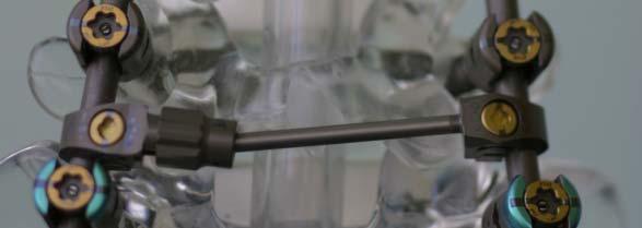

1 QUANTUM SPINAL ROD SYSTEM Key Features Presenter: John Perala, Product Manager August 14, 2006


2 Fixed Screw Sizes , 25-40mm 7.75, 30-50mm 5.75, 25-40mm , 30-40mm 6.75, 30-50mm


3 Polyaxial Screw Sizes 4.75, 25-50mm 6.75, 30-55mm 5.75, 30-50mm 7.75, 30-55mm

")
")
")
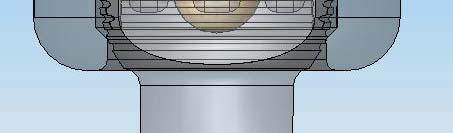
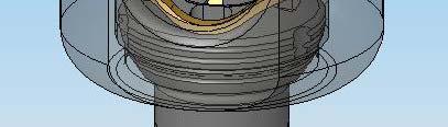
4 Polyaxial Screw Design 1) Screw Head 2) Gimbal Clip 3) Rotating Anvil 4) Screw Shaft


5 Polyaxial Screw Pivoting rod contact - Anvil Gimbal Retaining Clip 20 degrees of angulation rotating 360 degrees


6 Key Instrumentation Screw Inserter Knurled Knob used to tighten screw to instrument. Controls Bosses/Posts. Bosses/Posts Removable Handle


7 Key Instrumentation Screw Inserter Drive Points (4) Must be fully engaged Screw Inserter Bosses/Posts Screw Inserter Bosses/Posts will engage screw head holes
; Minor Dia. (.158in/4.00mm) 6.75mm - Major Dia. (.262in/6.")
; Minor Dia. (.246in/6.")
8 Screw Size - Major & Minor Diameters 4.75mm - Major Dia. (.188in/4.75mm); Minor Dia. (.120in/3.00mm) 5.75mm - Major Dia. (.226in/5.75mm); Minor Dia. (.158in/4.00mm) 6.75mm - Major Dia. (.262in/6.65mm); 65 Minor Dia. (.178in/4.50mm) 7.75mm - Major Dia. (.305in/7.75mm); Minor Dia. (.218in/5.50mm) 8.75mm - Major Dia. (.346in/8.75mm); Minor Dia. (.246in/6.25mm) Major = outside thread dimension Minor = inside thread dimension


9 Polyaxial Screw Summary Top Loading Pivoting rod contact - Anvil Low Profile Rod Reduction Instrumentation Rotates 360 degrees Polyaxial Angulation 20 degrees


10 QUANTUM U SPINAL ROD SYSTEM S Locking Cap Design & Sequence of Stages Blocking 10 degree Allows free movement Stopping 45 degree Allows & holds compression & distraction, and rod rotation Locking 100 degree Marks aligned and anvil compressed. Screw/rod fixed CENTRALIZED CAMMING 98 in-lb average locking torque


11 Value Proposition for Cap (Centralized Camming) Consistent Torque Repeatable feel Three distinct stages Visual, tactile, hard stop No variation in torque No tool calibration No cross threading


12 Key Instrumentation Initial Inserter, Final Locker & Stabilizing Tube Final Locker for final locking Stabilizing Tube allowing for counter-torque torque Initial Cap Inserter - has a tapered tip for loading cap and only used for initial iti insertion and provisional i positioning i

 with")
13 Key Instrumentation Locking Tube Used for Locking Cap into final locking position (100 degrees) with counter-torque.


14 Key Instrumentation Locking Sequence Locking 100 degree Marks aligned and anvil compressed. Screw/rod fixed Stopping 45 degree pp g g Allows & holds compression & distraction, and rod rotation
 Flexible,")


15 Locking Cap Summary ¼ Turn Final Locking (100 degree) Flexible, Intermediate Locking Compression & Distraction & Rod Rotation Visual & Tactile confirmation Mechanical Stop 98 in-lb average locking torque


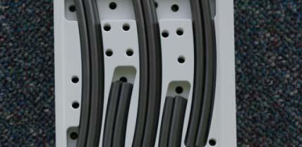
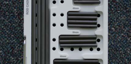
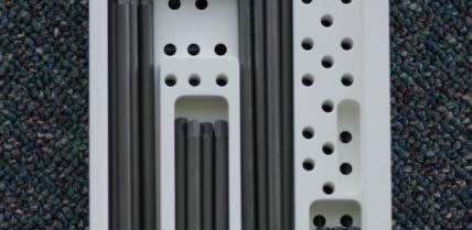
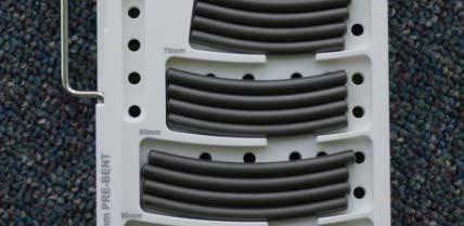
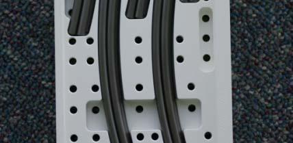
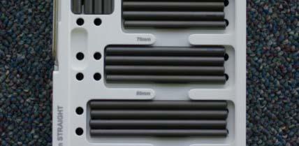
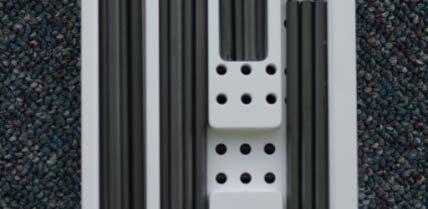


16 Pre-Bent & Straight Rod Sizes 35mm 150mm 35mm 110mm & 120, 150, 200, 400mm
17 Pre-Bent Rod Angulation 5.5 mm diameter


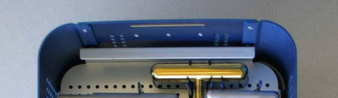
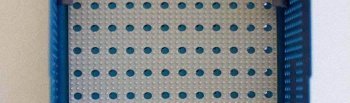
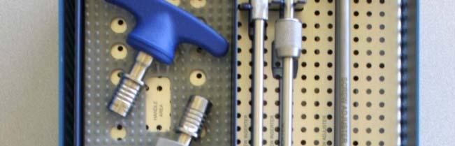
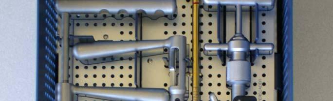
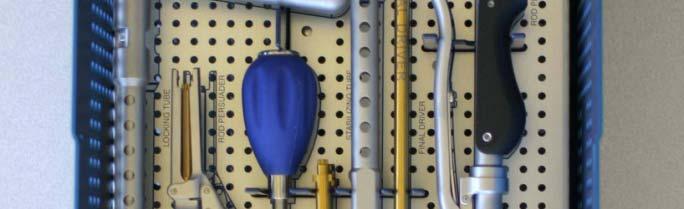
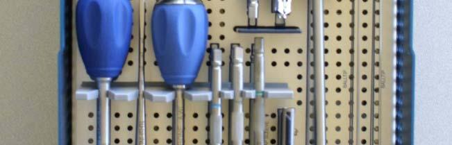
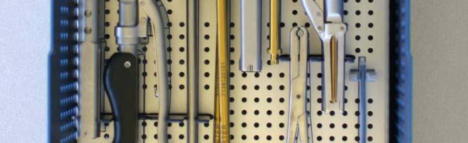

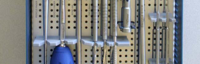
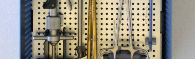
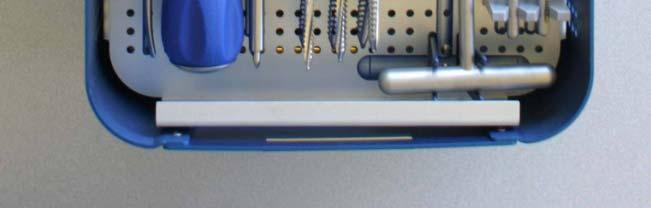
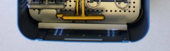
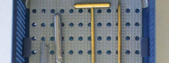
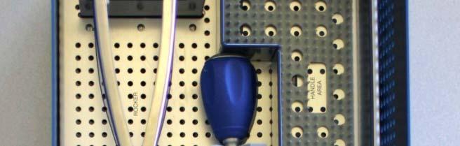
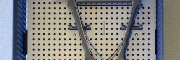
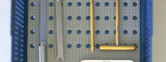
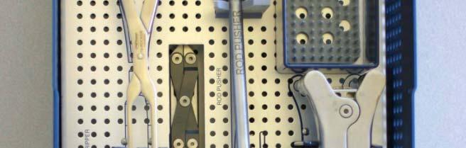
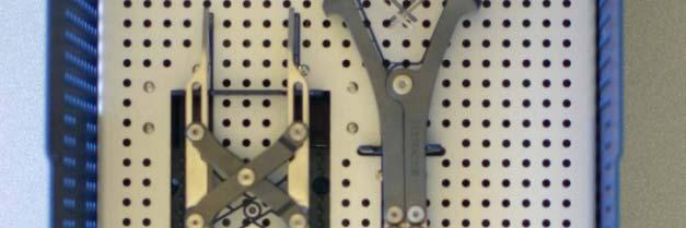
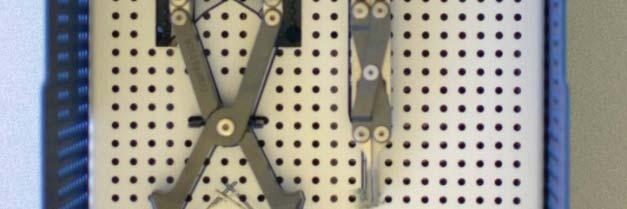
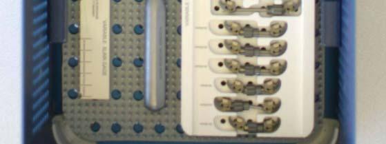
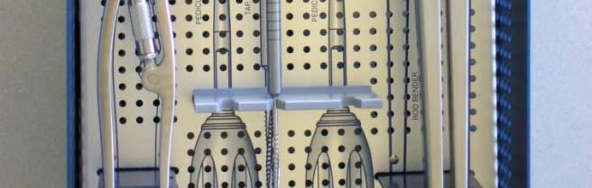
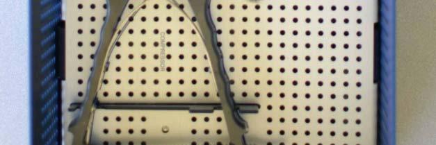
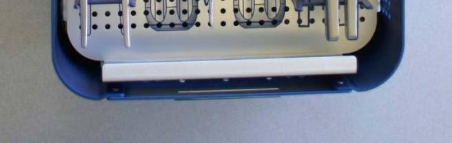
18 QUANTUM - Primary Case Bottom Tray Upper Tray Lower Tray


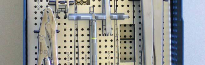
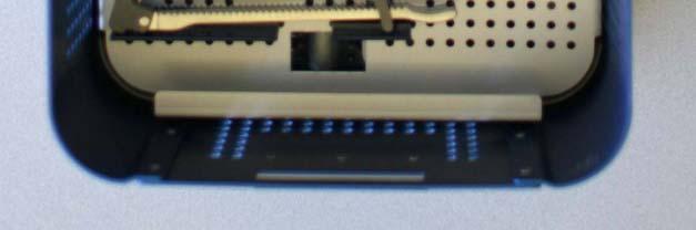
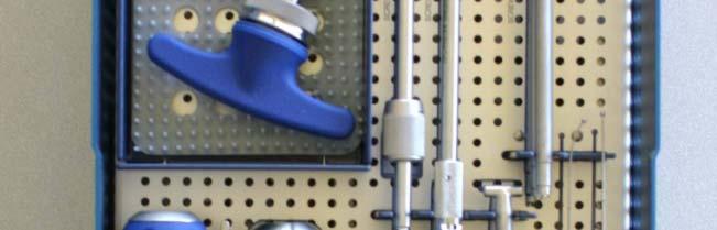
19 QSRS - Secondary Case Bottom Tray Upper Tray Lower Tray
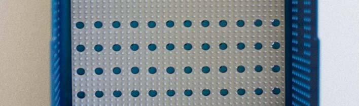
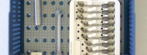
20 QUANTUM - Implant Case Space Available for either Fixed Screw or Auxiliary Caddies
 T-Handle 2)")
 Shaft 5)")
21 Key Instrumentation Rod Persuader 1) T-Handle 2) Torque Bar 3) Squeeze Handle 4) Shaft 5) Persuader Jaws


22 Key Instrumentation Rod Persuader Sequence Cap engaging Screw Head awaiting provisional locking C h i t l iti Cap shown in a neutral position traveling down Persuader jaws

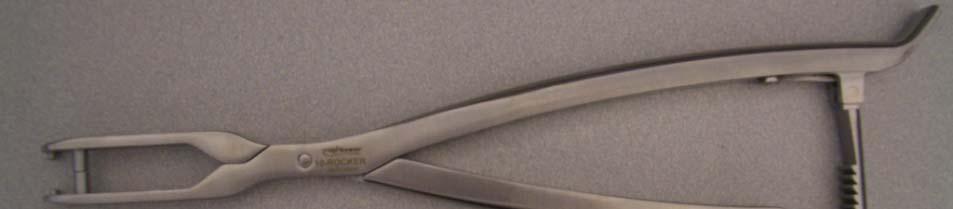

23 Key Instrumentation Other Rod Reduction Options Rocker Yoke Fork


24 Key Instrumentation Tap & Tap Sleeve


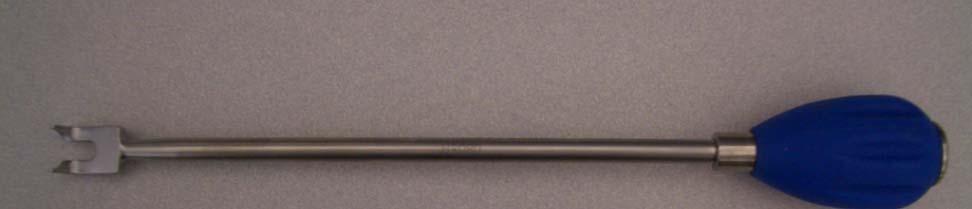
25 Key Instrumentation Swizzle Stick & Screw Adjuster Used for rotating and positioning Screw Head Used for fine adjustment of screw
26 Any Questions?
Pangea Degenerative Spine System. Top Loading Preassembled Pedicle Screw System for Posterior Stabilization of the Thoracolumbar Spine.
 Technique Guide Pangea Degenerative Spine System. Top Loading Preassembled Pedicle Screw System for Posterior Stabilization of the Thoracolumbar Spine. Contents Introduction AO ASIF Principles 4 Indications
REXIOUS SPINAL SYSTEM
 REXIOUS SPINAL SYSTEM SURGICAL TECHNIQUE www.diomedical.com. Site Preparation. Screw Insertion 3. Rod Preparation and Insertion 4. Rod Instruction 5. Set screw Insertion 6. Compression, Distraction & Rotation
Optima ZS Spinal Fixation System
 Surgical Technique Optima ZS Spinal Fixation System The low-profile, in-line, polyaxial pedicle screw system. Optima ZS Surgical Technique 1 Optima ZS Spinal Fixation System The Optima ZS Spinal Fixation
Surgical Technique ANAX TM OCT. Spinal System
 Surgical Technique ANAX TM OCT Spinal System Product Overview Occipital plate Medial occipital plate (Small, Medium, Large) Lateral occipital plate (Small, Medium, Large) Cortical screw (D4.5mm), Rescue
Aesculap Spine S 4 Spinal System. Instrumentation Guide
 Aesculap Spine S 4 Spinal System Instrumentation Guide S 4 Spinal System S 4 From initial conception, the S 4 Spinal System was developed to meet the spine surgeon s need for an extremely low profile and
BLACKBIRD Spinal System
 BLACKBIRD Spinal System Cervical-Thoracic Spinal Fixation System The ChoiceSpine BLACKBIRD Cervical-Thoracic Spinal Fixation System is a comprehensive system for posterior fixation of the cervical and upper
URS Degen. Top loading pedicle screw system for posterior stabilization.
 URS Degen. Top loading pedicle screw system for posterior stabilization. Technique Guide This publication is not intended for distribution in the USA. Table of Contents Introduction URS Degen 2 AO Principles
PRODUCT SUMMARY. 80 Total Angulation
 PRODUCT SUMMARY 80 Screw Angulation 40 40 80 Total Angulation 3 Directions of Freedom in Cross Link Low Profile Screws Sizes Available in 3.5mm and 4.0 mm diameters Accomodates 3.5 mm rod Self Drilling,
The Percutaneous Reduction Forceps Technique Guide
 The Percutaneous Reduction Forceps Technique Guide Indications + Product Overview Introduction The Percutaneous Reduction Forceps The Percutaneous Reduction Forceps facilitate standard technique for fixation
Anterior Cervical Plate SURGICAL TECHNIQUE GUIDE. Surgeon Driven Innovation
 Anterior Cervical Plate SURGICAL TECHNIQUE GUIDE Surgeon Driven Innovation 1 The Snowmass Anterior Cervical Plate System is intended for the surgical treatment and correction of traumatic and pathologic
Top Loading Pedicle Screw and Hook System for Posterior Stabilization. URS System. Surgical Technique
 Top Loading Pedicle Screw and Hook System for Posterior Stabilization URS System Surgical Technique Image intensifier control This description alone does not provide sufficient background for direct use
Surgical Technique. Deformity - Degenerative. Interbody Fusion. Tumour - Trauma. Cervical. Emerging Technology
 Surgical Technique Deformity - Degenerative Interbody Fusion Tumour - Trauma Cervical Emerging Technology MONARCH SPINE SYSTEM Contents Introduction & Philosophy 2 Surgical Technique Monarch Bolts with
S 4. Aesculap. Spinal System. Percutaneous Approach Surgical Technique. Aesculap Spine
 Aesculap Percutaneous Approach Surgical Technique S 4 Spinal System Aesculap Spine S 4 Spinal System Small The S 4 Spinal System features a revolutionary pressure vessel design capable of delivering unmatched
CD HORIZON REDUCTION MULTI AXIAL SCREW. Spinal System Technical Guide
 CD HORIZON REDUCTION MULTI AXIAL SCREW Spinal System Technical Guide T E C H N I C A L G U I D E CD HORIZON REDUCTION MULTI AXIAL SCREW Spinal System The following describes reduction of a spondylolisthesis
Synapse System. An enhanced set of instruments and implants for posterior stabilization of the upper spine.
 Synapse System. An enhanced set of instruments and implants for posterior stabilization of the upper spine. Technique Guide 100º Instruments and implants approved by the AO Foundation Table of Contents
Xia 3 Reference Guide. Version 3-August 2015
 Xia 3 Reference Guide Xia 3 Reference Guide Version 3-August 2015 Table of Contents Implants 03 Blocker 03 Monoaxial Screws 04 Polyaxial Screws 05 Uniplanar Screws 06 Iliac Bolts 07 Rod-to-Rod Connectors
Technique Guide. Synapse System. An enhanced set of instruments and implants for posterior stabilization of the cervical and upper thoracic spine.
 Technique Guide Synapse System. An enhanced set of instruments and implants for posterior stabilization of the cervical and upper thoracic spine. Table of Contents Introduction Synapse System 2 AO Principles
SYnaPSe oct SYSteM. An enhanced set of instruments and implants for posterior stabilization of the upper spine
 SYnaPSe oct SYSteM An enhanced set of instruments and implants for posterior stabilization of the upper spine SurgIcal technique Table of Contents Introduction SYNAPSE OCT System 2 AO Principles 5 Indications
Part Name Part Number Quantity
 Part Name Part Number Quantity Flex Arm Adapter Triangular 03.612.013 2 3mm Drill Bit with Stop 16mm 324.16 1 2.5mm Drill Bit with Stop 13mm 324.152 1 2.5mm Drill Bit with Stop 16mm 324.155 2 2.5mm Drill
Aviator Anterior Cervical Plating System System Overview. Visual and tactile confirmation Increased Angulation Simplified instrumentation
 Aviator Anterior Cervical Plating System System Overview Visual and tactile confirmation Increased Angulation Simplified instrumentation The Aviator anterior cervical plating system offers a unique double
ACCS Anterior Cervical Compression System TECHNIQUE GUIDE
 ACCS Anterior Cervical Compression System TECHNIQUE GUIDE Original Instruments and Implants of the Association for the Study of Internal Fixation AO ASIF ACCS Anterior Cervical Compression System The Anterior
SURGICAL TECHNIQUE. SpineTune THORACO-LUMBAR POSTERIOR OSTEOSYNTHESIS SYSTEM
 SURGICAL TECHNIQUE SpineTune TM TL THORACO-LUMBAR POSTERIOR OSTEOSYNTHESIS SYSTEM SURGICAL TECHNIQUE SpineTune TM TL Table of Contents page Step 1 - Site preparation.......................................................................................
Vortex TRAUMATOLOGY. Vortex Distal Femur
 Vortex TRAUMATOLOGY Vortex Distal Femur 1 Content 1. Introduction 4 4. Implant list 16-17 The following surgical description contains general outlines for Vortex Distal Femur plating. However, the operating
3-SPEED TRANSMISSION TEARDOWN GUIDE
 3-SPEED TRANSMISSION TEARDOWN GUIDE Toro Service Training Material 3-Speed Transmission Teardown This is an exercise to take apart a 3-Speed transmission just as you would if one fails on a customer s
Technique Guide. Occipito-Cervical Fusion System. Implants and instruments designed to optimize fixation to the occiput.
 Technique Guide Occipito-Cervical Fusion System. Implants and instruments designed to optimize fixation to the occiput. Table of Contents Introduction Overview 2 AO ASIF Principles 4 Indications and Contraindications
VLP FOOT Variable Angle Locked Plating System
 Surgical Technique VLP FOOT Variable Angle Locked Plating System Surgical Technique Table of Contents Product overview Implant selection...2 Introduction...3 System overview...4 Indications...4 Design
Vertebral Body Derotation System Guide and Ordering Information
 Vertebral Body Derotation System Guide and Ordering Information Introduction DePuy Spine continues to support the goal of providing solutions to surgeon challenges when treating spinal disorders. Collaborating
Cervical Solutions. Lineum OCT. Spine System. Surgical Technique Guide
 Cervical Solutions Lineum OCT Spine System Surgical Technique Guide 2 Lineum OCT Spine System Surgical Technique Guide Designed to encourage optimal screw placement and procedural efficiency Lineum OCT
400GTO Lubrication Guide
 400GTO Lubrication Guide Lubrication Guidelines for the following equatorial mounting: 400GTO Servo with GTOCP2 or CP3 Controller For other 400 models please review other postings as they become available.
Thoracolumbar Solutions. Vitality Spinal Fixation System. Surgical Technique Guide
 Thoracolumbar Solutions Vitality Spinal Fixation System Surgical Technique Guide Vitality Spinal System Surgical Technique Vitality Spinal System Surgical Technique Description, Indications and Contraindications...
1.5 MM LCP SYSTEM. For treatment of fractures and arthrodeses of canines and felines SURGICAL TECHNIQUE
 1.5 MM LCP SYSTEM For treatment of fractures and arthrodeses of canines and felines SURGICAL TECHNIQUE TABLE OF CONTENTS INTRODUCTION 1.5 mm LCP System 2 AO Principles 4 SURGICAL TECHNIQUE Reduce Fracture
OPERATIVE TECHNIQUE COVER IMAGE OPTIONAL (DETAIL) IMAGE FIREBIRD NXG. spinal fixation system
 IMAGE FIREBIRD NXG. spinal fixation system") OPERATIVE TECHNIQUE COVER IMAGE OPTIONAL (DETAIL) IMAGE FIREBIRD NXG spinal fixation system TABLE OF CONTENTS Introduction 1 Operative Technique 2 Reduction Body Technique 18 Implants and Instruments 24
OPERATIVE TECHNIQUE COVER IMAGE OPTIONAL (DETAIL) IMAGE FIREBIRD NXG spinal fixation system TABLE OF CONTENTS Introduction 1 Operative Technique 2 Reduction Body Technique 18 Implants and Instruments 24
MODEL T10050 RIGHT ANGLE IRON BENDER INSTRUCTIONS
 MODEL T10050 RIGHT ANGLE IRON BENDER INSTRUCTIONS Damage to your eyes, face, and hands could result from using this item without proper protective gear, such as safety glasses or a face shield, and gloves.
OPERATION AND MAINTENANCE HANDBOOK D407270XA
 OPERATION AND MAINTENANCE HANDBOOK D407270XA vers. 1.0 Thank you for choosing one of Silca s high quality key cutting machines. This machine has been designed, tested and produced in our factory using
Maintenance Information
 16601023 Edition 2 January 2014 Air Impact Wrench 2705P1 Maintenance Information Save These Instructions Product Safety Information WARNING Failure to observe the following warnings, and to avoid these
Quill Stop V2 Installation Guide 11/16/2014
 Thank you for purchasing the Quill Stop for the Sieg X3 (Grizzly G0463) and SX3 (Grizzly G0619) mills. Your feedback is always appreciated. Please email questions and comments to gregpriest@cox.net. What
DRILL GRINDING ATTACHMENT
 DRILL GRINDING ATTACHMENT To suit TM6025Q TOOL AND CUTTER GRINDER OPERATION S MANUAL 1 0º 270º 90º 180º INTRODUCTION Before grinding any cutters, you must set up the attachment to suit the type of cutter
VBOSS. Surgical Technique. Vertebral Body Support System
 VBOSS Surgical Technique Vertebral Body Support System 1. System Description 1.1 Implants...3 1.2 Instruments...4 2. Indications...8 3. Patient Position...8 4. Surgical Approach 4.1 Choice of adequate
DLS Dynamic Locking Screw. Combined with LCP Locking Compression Plate.
 DLS Dynamic Locking Screw. Combined with LCP Locking Compression Plate. Instructions for Use Discontinued June 2016 DSEM/TRM/0517/0844(1) Table of Contents Introduction DLS Dynamic Locking Screw 2 Indications
POLYAXIAL SPINE SYSTEM
 S U R G I C A L T E C H N I Q U E En POLYAXIAL SPINE SYSTEM S C O L I O S I S INSTRUMENTATION A02240010 Pedicle hook starter A02240020 Laminar and transverse process hook starter A02240030 Compressor forceps
6.5 mm and 7.3 mm Cannulated Screws Technique Guide
 6.5 mm and 7.3 mm Cannulated Screws Technique Guide An Integral Part of the SYNTHES Cannulated Screw System Original Instruments and Implants of the Association for the Study of Internal Fixation AO ASIF
LCP Pilon Plate 2.7/3.5
 Surgical Technique LCP Locking Compression Plate Original Instruments and Implants of the Association for the Study of Internal Fixation AO/ASIF Table of contents Indications 3 Implants 4 Instruments 5
KIT. Assembly Instructions. HayDay, LLC
 KIT Assembly Instructions HayDay, LLC 1-800-732-1654 www.stablegrazer.com Read completely through the assembly instructions before starting assembly. The Stable Grazer Kit comes in two boxes. Remove all
VBOSS Surgical Technique
 VBOSS Surgical Technique 1 2 CONTENT 1. System Description 4 1.1 Implants 4 1.2 Instruments 6 2. Indications 11 3. Patient Position 11 4. Surgical Approach 12 4.1 Choice of adequate Parallel Distractor
Ankle Fracture System. Surgical Technique STRENGTH FROM WITHIN
 Ankle Fracture System Surgical Technique STRENGTH FROM WITHIN Ankle Fracture System The Sonoma FibuLock nail is the first intramedullary device that has the same indications as plates and delivers anatomic
Passage 4 Bike Hitch Rack
 Thank you for purchasing the XPORT Passage 4 Bike Hitch rack. This rack will securely carry up to 4 bicycles. The trigger and lift assist mechanisms allow the rack to tilt up or down allowing easy access
Interlagos Retractor System Surgical Technique
 Interlagos Retractor System Surgical Technique TABLE OF CONTENTS Instructions for Use Design Rationale Surgical Technique 1. Pre-Operative Preparation 2. Pedicle Preparation 3. Primary Retraction 4. Secondary
E4-WM5-Y525A00 MOUNTING INSTRUCTION
 RAM 2500/3500 4WD B8 5100 (Dual Steering Damper Kit) The installation of these steering dampers must be performed only by experienced and qualified personnel. Read and follow the installation instructions
Technique Guide. Variable Angle LCP Opening Wedge Plates 2.4/2.7. Part of the Variable Angle LCP Forefoot / Midfoot System 2.4 / 2.7.
 Technique Guide Variable Angle LCP Opening Wedge Plates 2.4/2.7. Part of the Variable Angle LCP Forefoot / Midfoot System 2.4 / 2.7. Table of Contents Introduction Variable Angle LCP Opening Wedge Plates
REPAIR INSTRUCTIONS. Cat. No Cat. No MILWAUKEE ELECTRIC TOOL CORPORATION. SDS Max Demolition Hammer. SDS Max Rotary Hammer
 Cat. No. 9-0 SDS Max Demolition Hammer Cat. No. -0 SDS Max Rotary Hammer MILWAUKEE ELECTRIC TOOL CORPORATION W. LISBON ROAD BROOKFIELD, WISCONSIN 00-0 8-9-0 d 000 8-9-0 d Special Tools Require Forcing
Technique Guide. LCP Pilon Plate 2.7/3.5
 Technique Guide LCP Pilon Plate 2.7/3.5 LCP Pilon Plate 2.7/3.5 Table of contents Indications 3 Implants 4 Instruments 5 Surgical technique 6 Implant removal 12 Image intensifier control Warning This
Thoracolumbar Solutions. Polaris. Deformity System. Trivium. Derotation System. Surgical Technique Guide
 Polaris Deformity System Thoracolumbar Solutions Trivium Derotation System Surgical Technique Guide 2 Polaris Deformity System and Trivium Derotation System Surgical Technique Guide Polaris Deformity System
Instructions for Use. LCP Locking Compression Plate. Combine without Compromise.
 Instructions for Use LCP Locking Compression Plate. Combine without Compromise. Table of Contents LCP: Combine without Compromise 2 AO ASIF Principles of Osteosynthesis 4 Indications and Contraindications
TRULY POLYAXIAL, SOLID AND POWERFUL
 S U R G I C A L T E C H N I Q U E V2 TRULY POLYAXIAL, SOLID AND POWERFUL P O L Y A X I A L S P I N E S Y S T E M a decade of results P O L Y A X I A L S P I N E S Y S T E M TRULY POLYAXIAL, SOLID AND POWERFUL
Page 1. SureMotion Quick-Start Guide: LARSACC_QS 1st Edition - Revision A 03/15/16. Standard Steel Bolt/Screw Torque Specifications
 R K C T I Repair Kit Product Compatibility Repair Kit # Linear Actuator Assembly # LARSACC-013 LARSACC-014 LARSD2-08T12BP2C (12-in travel) LARSD2-08T24BP2C (24-in travel) C P I R K 1 ea Ball Screw with
ACLP Anterior Cervical Locking Plate System TECHNIQUE GUIDE
 ACLP Anterior Cervical Locking Plate System TECHNIQUE GUIDE Instruments and implants approved by the AO Foundation ACLP Anterior Cervical Locking Plate System The ACLP System is designed to reduce the
SERVICE PARTS LIST PAGE 1 OF 6 BASE ASSEMBLY SPECIFY CATALOG NO. AND SERIAL NO. WHEN ORDERING PARTS 12" SLIDING COMPOUND MITER SAW
 PAGE 1 OF 6 BASE ASSEMBLY 00 0 CATALOG NO. EXAMPLE: SPECIFY CATALOG NO. AND NO. WHEN ORDERING PARTS 6955-20 1 02-80-0050 Thrust Bearing (1) 2 05-80-0510 M5 x 12mm Flat Head T-20 Screw (5) 3 05-81-0135
SECTION 9: PARTS. Electrical Box. (0000 Series Parts) 0000 Series Parts List
 0000 Series Parts List") SECTION 9: PARTS Electrical Box (0000 Series Parts) 0000 Series Parts List 1 P04920001 CONTACTOR 6 P04920006 FUSE 2A (LC1-D0910, B5, 24V, 50HZ) 7 P04920007 FUSE HOUSING 2 P04920002 CONTACTOR 8 P04920008
SECTION 9: PARTS Electrical Box (0000 Series Parts) 0000 Series Parts List 1 P04920001 CONTACTOR 6 P04920006 FUSE 2A (LC1-D0910, B5, 24V, 50HZ) 7 P04920007 FUSE HOUSING 2 P04920002 CONTACTOR 8 P04920008
AR-15 Armorer s Essentials Kit. Product # Instructions # Revision: B
 AR-15 Armorer s Essentials Kit Product #156111 Instructions #1025769 Revision: B 1 INDEX 3 AR-15 Adjustable Receiver Link 3 Pivot Pin and Roll Pin Installation Tool 4 Mag well Vise Block 7 Upper Vise Block
Lag Screw Device TECHNIQUE GUIDE. Indicated for symphyseal fracture fixation of the mandible. Instruments and implants approved by the AO Foundation
 Lag Screw Device TECHNIQUE GUIDE Indicated for symphyseal fracture fixation of the mandible Instruments and implants approved by the AO Foundation Lag Screw Device Indicated for symphyseal fracture fixation
Interactive Monitor Arm
 Interactive Monitor Arm Tools Required -5mm Allen wrench -Phillips screwdriver -Plastic mallet There are two ways to attach a Monitor Arm to a Full Frame; with a Beam, or with a Post Mount. Both methods
TITAN2-EDGE Public Access Computer Station Dual Track
 TITAN2-EDGE Public Access Computer Station Dual Track TITAN2-EDGE Rev A 6/17 Model TITAN2-EDGE ASSEMBLY AND ADJUSTMENT TITAN2-EDGE PARTS AND TOOLS PLEASE REVIEW these instructions before beginning the
NELSON STUD WELDING ACCESSORY SPECIFICATION: Stud Weld Gun Imperial Dimension Chucks
 Type 1 4 #2 Morse Taper Mounting NELSON STUD WELDING ACCESSORY SPECIFICATION: Stud Weld Gun s Below is a list of standard imperial chucks for use in welding Nelson studs. The chucks are listed with both
MODEL T21973 METAL BLADE GUIDE SET INSTRUCTIONS
 MODEL T21973 METAL BLADE GUIDE SET INSTRUCTIONS Introduction (Figure 1) These Euro-style blade guides replace the blade guides on the G0531, G0531B, G0566, G0568, and G0569 bandsaw. Tools Needed Wrench
Reflex TM Surgical Technique. Anterior Cervical Plate
 Reflex TM Surgical Technique Anterior Cervical Plate Surgical Technique Acknowledgement: Stryker Spine extends their thanks to the following surgeons for their participation in the development of the Reflex
BOW-A-CONSTRICTOR BUCKEYE ARCHERY SOLUTIONS
 BOW-A-CONSTRICTOR BUCKEYE ARCHERY SOLUTIONS User Guide: Bow-A-Constrictor Tuning Station Note: The following instructions begin with the power bar tongue set at approximately the 6th hole from the crank.
Travis Bishop. Submitted to: Dr. John Davis. Date: 3 December Course: ETME 310 Section: 004. Lab Topic: Milling Project (Vise)
") Travis Bishop Submitted to: Dr. John Davis Date: 3 December 2012 Course: ETME 310 Section: 004 Lab Topic: Milling Project (Vise) Introduction: Purpose of Experiment: This experiment was conducted to teach
Travis Bishop Submitted to: Dr. John Davis Date: 3 December 2012 Course: ETME 310 Section: 004 Lab Topic: Milling Project (Vise) Introduction: Purpose of Experiment: This experiment was conducted to teach
Technique Guide. Synapse System. An enhanced set of implants and instruments for posterior stabilization of the cervical and upper thoracic spine.
 Technique Guide Synapse System. An enhanced set of implants and instruments for posterior stabilization of the cervical and upper thoracic spine. Image intensifier control Warning This description alone
SERVICE PARTS LIST PAGE 1 OF 6 BASE ASSEMBLY SPECIFY CATALOG NO. AND SERIAL NO. WHEN ORDERING PARTS 12" DUAL BEVEL COMPOUND MITER SAW B27B
 PAGE 1 OF 6 BASE ASSEMBLY 00 0 EXAMPLE: Component Parts (Small #) Are Included When Ordering The Assembly (Large #). SPECIFY CATALOG NO. AND NO. WHEN ORDERING PARTS = Part number change from previous service
Click Here to Go Back
 Click Here to Go Back Fig. -94 Fig. -97 CC42D 10. Remove the cap screw securing the gear shift stopper plate pin retainer; then remove the retainer. Fig. -95 CC45D 12. Remove the link arm and account for
Line volt rail & fixtures. Low volt quick connect fixtures with transformers
 INSTRUCTIONS: Line Volt Flexrail2 Safety Instructions: A qualified electrician must install system only. System is intended for installation in accordance with National Electric Code, local and Federal
Tools: Sharpie, Square, Vise, Hack saw, Ruler, Punch, Hammer, File. 2. Cut the stock Place stock in vise and cut with hack saw
 Purpose: MAKE CATAPULT ARM Step 1 Tools: Sharpie, Square, Vise, Hack saw, Ruler, Punch, Hammer, File Materials: Flat aluminum ½ inch stock (see picture below) Gloves required 1. Pick up the aluminum ½
Installation Instructions. Installation Type
 Installation Instructions 800 & 8050 Slide Track Door Closers Non Hold Open & Hold Open Models Note: Hold open models are not permitted to be installed in Listed fire door assemblies. PULL SIDE MOUNTED
vw-wi://rl/a.en-gb.a00.5a60.27.wi:: xml?xsl=3
 Page 1 of 7 Removing and installing balance shaft assembly Special tools and workshop equipment required Locking pin -T10115- Locking tool -T10255- Removing Remove sump Chapter. Rotate crankshaft to TDC
END FEED INSTALLATION
 STARLINE PLUG-IN RACEWAY END FEED INSTALLATION The Universal End Feed (product numbers beginning with URPF, URDF, or MRPF, MRDF) provides the installer a provision to connect supply power to the Plug-In
SECTION 7. SAFETYING
 9/8/98 AC 43.13-1B SECTION 7. SAFETYING 7-122. GENERAL. The word safetying is a term universally used in the aircraft industry. Briefly, safetying is defined as: Securing by various means any nut, bolt,
SAFETY INSTRUCTIONS. Wear protective clothing, including safety glasses and steel toe boots.
 SAFETY INSTRUCTIONS Wear protective clothing, including safety glasses and steel toe boots. DO NOT allow loose clothing or long hair near machine operations. Keep work site and machine clean. Use brush
INSTRUCTIONS 360 CHAINROLL
 INSTRUCTIONS 360 CHAINROLL 360 CHAINROLL REGISTRATION Please visit productregistration.360yieldcenter.com to complete the product registration for your 360 CHAINROLL so we can better support our products
Installation Instructions. Installation Type
 Installation Instructions 300 & 3050 Slide Track Door Closers Non Hold Open & Hold Open Models Note: Hold open models are not permitted to be installed in Listed fire door assemblies. PULL SIDE MOUNTED
DO35 MAINTENANCE INSTRUCTIONS
 CUSTOMER INFORMATION SHEET NO. 038 DO35 MAINTENANCE INSTRUCTIONS (DO35 V3 LAUNCHED PRODUCTION JUNE 2017) Table of Contents 1.0 Replacing Spindle Bushes V3... 22 2.0 Replacing Locking Mechanism V3... 6
Technique Guide Supplement. Standard DHS Lag Screw with LCP DHHS Sideplate.
 Technique Guide Supplement Standard DHS Lag Screw with LCP DHHS Sideplate. Table of Contents Surgical Technique Standard DHS Lag Screw with LCP DHHS 2 Sideplate Technique DHS One-step Lag Screw with DHHS
MERRIDALE STREET WEST WOLVERHAMPTON
 Instructions Boring "Wandess" Cylinder Boring Bar Whatton & Sons, Ltd MERRIDALE STREET WEST WOLVERHAMPTON The "Wandess" Cylinder Boring Bar GENERAL : Introduction of the Wandess Cylinder Boring Bar marks
Service Manual. Chipper/Shredder - CS4210 and CS4265 IMPORTANT: READ SAFETY RULES AND INSTRUCTIONS CAREFULLY
 Service Manual Chipper/Shredder - CS4210 and CS4265 IMPORTANT: READ SAFETY RULES AND INSTRUCTIONS CAREFULLY This Service Manual is not a substitute for the Operator s Manual. You must read, understand
MAG-CONV Basic, 48, 48R & Midline Front Mount
 Parts Required: Tools Used: Mag Wheels Brakes Brake Rods Mounting Bracket Anti Tippers 7/16" Wrench Screw Driver Rubber Mallet 5/8 Wrench 5mm Allen Wrench Step Execution Figures 1 Remove front 5" total
ED1300/1300F SERIES CONCEALED VERTICAL ROD DEVICE INSTALLATION INSTRUCTIONS
 ED1300/1300F SERIES CONCEALED VERTICAL ROD DEVICE INSTALLATION INSTRUCTIONS Ver.2 1300 SERIES CONCEALED VERTICAL ROD DEVICE Top Strike Latch Screws Strike Screws Release Plunger Top Latch Plunger Screws
D. Greg Anderson, MD Thomas Jefferson University Hospital Philadelphia, PA
 Surgical Technique D E S I G N I N G S U R G E O N S D. Greg Anderson, MD Thomas Jefferson University Hospital Philadelphia, PA Robert Heary, MD University of Medicine and Dentistry of New Jersey Newark,
AndyMark DART 12.
 AndyMark DART 12 Part Number Description QTY These Parts Are Pre-Assembled by AndyMark am-0031 Bearing, 3/16"ID (R3) 1 am-0209 Bearing, 3/8"ID 1614ZZ 2 am-1028 Screw, #10-32x3/8 Pan Head Philips 8 am-1121
Small Plate and Screw System SURGICAL TECHNIQUE
 MINI MAXLOCK EXTREME Small Plate and Screw System SURGICAL TECHNIQUE Contents Key Design Features 2 Surgical Technique 3 Implants and Instruments 9 Proper surgical procedures and techniques are the responsibility
MODEL H9565 BALL BEARING GUIDE FOR G0513/G0514 INSTRUCTION SHEET
 MODEL H9565 BALL BEARING GUIDE FOR G0513/G0514 INSTRUCTION SHEET Introduction The Model H9565 replaces the upper and lower Euro-style guides on your G0513 or G0514 Bandsaw. Inventory (Figure 1) A. Upper
Parts Catalog. S-Series Slicer Manual Frozen Option S13. Model:
 , 07 995 ECN 08 Parts Catalog S S-Series Slicer Manual Frozen Option Model: S 05/0/07 Rev. G IMPORTANT! TO EXPEDITE SHIPMENT OF PARTS, ALWAYS SPECIFY MODEL, REV, PART NUMBER, AND SERIAL NUMBER OF UNIT.
Fig. 2 DORMA-Glas Stand/Issue 02/03 Seite/Page 1/7
 FSW Installation instructions Track rail 75 x 72 mm 1. Ceiling substructure and installation of the track rail (Fig. 1): The track rail must be bolted over its entire length (including the stacking track
535A. Main Components. Pipe and Bolt Threading Machine. Printed in U.S.A. Ridge Tool Company/Elyria, Ohio, U.S.A.
 Pipe and Bolt Threading Machine A Main Components 0 Screw, Button Head /" - 0 x /" () Washer, Flat /" ()" Top Cover 0 Base Bottom Cover Screw, Pan Head # - x " () Carriage Assembly 0 Front Support Bar
Occipito-Cervical Fusion System. Implants and instruments designed to optimize fixation to the occiput.
 Occipito-Cervical Fusion System. Implants and instruments designed to optimize fixation to the occiput. Technique Guide This publication is not intended for distribution in the USA. Instruments and implants
3.5 mm Cannulated Screw Technique Guide
 3.5 mm Cannulated Screw Technique Guide An Integral Part of the SYNTHES Cannulated Screw System Original Instruments and Implants of the Association for the Study of Internal Fixation AO ASIF The 3.5 mm
OPERATIVE TECHNIQUE CENTURION POSTERIOR OCCIPITAL CERVICO-THORACIC (POCT) SYSTEM
 SYSTEM") OPERATIVE TECHNIQUE CENTURION POSTERIOR OCCIPITAL CERVICO-THORACIC (POCT) SYSTEM TABLE OF CONTENTS Introduction 2 System Overview 3 Cervical Operative Technique 4 Thoracic Operative Technique 10 Thoracic
OPERATIVE TECHNIQUE CENTURION POSTERIOR OCCIPITAL CERVICO-THORACIC (POCT) SYSTEM TABLE OF CONTENTS Introduction 2 System Overview 3 Cervical Operative Technique 4 Thoracic Operative Technique 10 Thoracic
MINI INSTRUMENTS & IMPLANTS
 Page 1 MINI INSTRUMENTS & IMPLANTS Page 2 JACOB CHUCK DRILL BITS MIS-001 1.1MM 45MM LENGTH MIS-002 1.5MM 70MM LENGTH MIS-003 2.0MM 85MM LENGTH MIS-004 2.7MM 85MM LENGTH QUICK COUPLING DRILL BITS MIS-005
Variable Angle LCP Mesh Plate 2.4/2.7. Part of the Variable Angle LCP Forefoot/Midfoot System 2.4/2.7.
 Variable Angle LCP Mesh Plate 2.4/2.7. Part of the Variable Angle LCP Forefoot/Midfoot System 2.4/2.7. Surgical Technique This publication is not intended for distribution in the USA. Instruments and implants
VECTRA SURGICAL TECHNIQUE. Anterior cervical plate system. This publication is not intended for distribution in the USA.
 VECTRA Anterior cervical plate system This publication is not intended for distribution in the USA. SURGICAL TECHNIQUE Image intensifier control This description alone does not provide sufficient background
Surface Vise 05G10.50
 Surface Vise 05G10.50 Patent Pending Introduction The Veritas Surface Vise can be used anywhere you can drill two 3 /4" diameter holes, approximately 6" to 10" apart. The front guide supports the unthreaded
Variable Angle LCP Forefoot/Midfoot System 2.4/2.7. Procedure specific plates for osteotomies, arthrodeses and fractures of the foot.
 Instruction for Use Variable Angle LCP Forefoot/Midfoot System 2.4/2.7. Procedure specific plates for osteotomies, arthrodeses and fractures of the foot. Table of Contents Introduction VA-LCP Forefoot/Midfoot