GE 100 Trebuchet Field Activity Instruction Sheet
|
|
|
- Polly McKenzie
- 5 years ago
- Views:
Transcription
1 GE 100 Trebuchet Field Activity Instruction Sheet Safety Instructions: 1) Make sure that at the time of trebuchet launch, no person is leaning over/or is in close proximity of the rotating arm. 2) Only use the provided soft clay projectiles. 3) Trebuchets must be inspected by a TA/ELA before launching, ensuring that: a. Knots, pin joints, bolts, and other connections are secure. b. The finger is adjusted so that the projectile is not launched backwards. Also, the finger bolt must be secure enough to prevent rotation of the finger. c. Trebuchets must be re-inspected after each modification. 4) There will be approximately one staff member for every 3-4 project groups. a. Staff members (ELAs/TAs) will be wearing yellow vests so that they are easy to identify. b. Staff members will be available to help answer questions in addition to inspecting trebuchets. c. Design decisions (fulcrum location, finger angle, wheels/no wheels, sling length) are up to the student group; staff members will allow students to make these decisions on their own, but supervise to ensure safety. 5) Do not launch if any person is in front of, behind, or leaning over the trebuchet. Ensure that no body part of any person is in the path of trebuchet + sling movement. 6) The sidewalks on the Bardeen Quad will be blocked at four locations, and caution tape will be used to block off the landing zone. Staff members will be standing watch at each sidewalk barricade to ensure pedestrians do not enter the landing zone. Students are not to enter the landing zone without permission. 7) Two staff members at the east end of the launch zone will each have a green flag. When they see that the landing zone is clear of people, they will raise their flag. Do not launch unless both green flags are raised.

2 Launch Area: Assembled Trebuchet:


 Wheels.")


3 Assembly Instructions: 1) Side Pieces. Bolt each side assembly to the base with three ¼ bolts. You can use the nutdrivers to tighten the bolts. Side Assembly Base a. Please ensure that the side pieces are attached such that the vertical oak boards are closest to the center of the trebuchet. b. Bolts should be installed with the bolt heads down and with one washer on each side of the bolt. Upside-down bolts will protrude unsafely from the bottom of the base. 2) Wheels. If your group decides to use wheels, attach them now to the base at each of the four corners using the machine screws. Washer Lock Washer a. Important: Install the machine screws with the screw heads up. Otherwise, the screw ends will protrude unsafely up through the top surface of the base, and may snag the sling during launch. b. Important: Machine screw threads can be stripped easily, even with just a screwdriver. Tighten the machine screws by holding the nut with your fingers and tightening the head with the screwdriver snugly.
 Fulcrum Guides.")

4 c. Use a lock washer with each machine screw to prevent the machine screws from vibrating loose. Also, to prevent screws from vibrating loose, do not wheel the trebuchets long distances. d. Tip: two wheels can be installed simultaneously by two group members to save time. 3) Fulcrum Guides. If the fulcrum guides (guide pipes) are not already installed, please complete this step with the help of an ELA or TA 1. Otherwise, SKIP THIS STEP. a. While holding the two guide pipes (3 long) between the two sidepiece holes with the threads pointed outward, slide the 3/8 shaft through the guides. Install the hitch pins on either side of the shaft to secure it. Installing the shaft helps maintain alignment of the guide pipes as they are threaded into the side pieces 2. b. By hand, thread each guide into its hole just 1-2 threads. If they are difficult to turn at this point, the guides may be misaligned. Ensure both guides are going in straight before fully installing either guide. c. Screw the guides in as far as possible by hand, and then tighten with pliers (obtain from a TA/ELA) until the base of the threads is flush with the wood surface. Tightening beyond this may cause the wood to split. 4) Assemble Throwing Arm: a. Install the center fulcrum guide pipe (2 long) into the throwing arm slot and install the two large nuts with washers. Tighten these nuts with the adjustable wrenches. Loosen these nuts to adjust fulcrum position, but be sure to retighten the nuts. b. Install the counterweights by sandwiching the large end of the throwing arm between the two weights. Slide the 1 diameter dowel through the weights and throwing arm. Once the large dowel is in position with the 3/8 holes visible on each side, tap the 3/8 dowels into the holes far enough to center them. 1 Please get help from an ELA/TA as the side pieces can be damaged easily during this 2 Correct alignment is important for getting the trebuchet to throw correctly.


 Attach the throwing arm to the rest of the trebuchet. Remove the fulcrum shaft.")

5 i. If you have difficulty installing a dowel, the fit may be too tight. If this is the case, use the sheet of sandpaper to reduce the pin diameter slightly so that it can be installed with light tapping. ii. If you need to remove one of the 3/8 dowels, use the ¼ steel shaft (6 long) as a punch with the hammer. Do not use the screwdriver to remove the dowel; it will damage the wooden dowel pin. c. Install the finger assembly. Bolt it on to the small end of the throwing arm as shown in the figure. The bolt head goes on the finger side with one washer under the head. The plastic sling anchor goes on the other side of the throwing arm under the nut. When installing the anchor, make sure that the pin is perpendicular to the throwing arm as shown. Adjust to the desired finger angle, and tighten securely to prevent rotation. 5) Attach the throwing arm to the rest of the trebuchet. Remove the fulcrum shaft. Have one person hold the throwing arm with the weights pointed down. Move the throwing arm so that the center fulcrum guide is between the other two fulcrum guides. Slide the shaft through all three guide pipes. Secure the shaft with the hitch pins. a. You may need to squeeze the side pieces together and adjust the location of the shaft to expose both hitch pin holes. b. If the guide pipes are not aligned (i.e., the shaft will not go through the guide pipes), first try loosening the 6 side piece bolts and making small adjustments to the side piece positions to get the guide pipes aligned. c. If that doesn t work, you will need to remove the guide pipes from the side pieces and reinstall them as described in step 3. 6) Attach sling cord and adjust sling length. a. Start by identifying the desired sling length.


6 b. Create a loop 3.5 long beyond the chosen length. c. Feed this loop through the hole closest to the center of the clamp. d. Feed the loop once more into the second hole furthest from the center of the clamp. e. Place the loop around the looping pin. f. Tighten the sling around the clamp. g. To change sling length, loosen cord around anchor and adjust cord position. Readjust pouch to center of sling. Launch Day Protocol: We will hold two launch days: one after you have designed your trebuchet experiments, and another after you have adjusted your design using the computer simulation. When you arrive at the quad please locate your trebuchet and move to the staging area behind the appropriate launch pad number. As shown in the figure below, all groups whose number ends in 1 lines up behind launch pad number 1, all groups whose number ends in 2 lines up behind launch pad number 2, and so on. Three groups will rotate through using the same launch pad. Ten groups can be launching simultaneously, but only two students from each group are allowed at the launch pad. All other group members must wait in the staging area. Group members can take turns being the ones to launch the trebuchet. All people in the launch area must wear safety glasses. Each group will be issue two safety glasses. These can be shared within the group.
 Return to staging area when launches are complete.")
7 Stay behind yellow rope unless you are launching 1) Approach launch pad when directed (two students per group) 2) Launch projectiles with no adjustments ) Return to the same line you went through before. Make adjustments before next launch ) Return to staging area when launches are complete. Between turns make your necessary adjustments in preparation for the next test. Have your trebuchet inspected before the next launch. When it is your turn to launch and you move your trebuchet to the launch pad, you will be given 1-2 projectiles. Be sure to record your design and distance for each launch. Do not make adjustments on the launch pad, only in the staging area. Once you are done launching, please exit the launch pad (with your trebuchet and toolbox) by walking south behind all of the other teams, and then return to the staging area. On the Launchpad: 1. Have your trebuchet inspect each time you move to the launch pad. 2. Ensure no one is in front of, behind, or above the trebuchet. 3. Verify that both green flags are raised. 4. Load the projectile and loop the sling around the finger.
8 5. Rotate the throwing arm back as far as possible. 6. While holding the arm in position, place the projectile on the base toward the front such that there is no slack in the sling. 7. Yell something so that people know you are launching. 8. Let go of the throwing arm, taking care to stay out of the path of the rotating arm and sling. 9. Watch your nano-pumpkin sail! 10. Observe and record distance. Trebuchet Competition: The group that achieves the longest range will be recognized in class after the second launch day, and at the Engineering Open House trebuchet demonstration. We are especially interested in the trebuchet design (the four variable values) that achieves this distance, so please record each design that you test.
Trebuchet Parts List and Overview
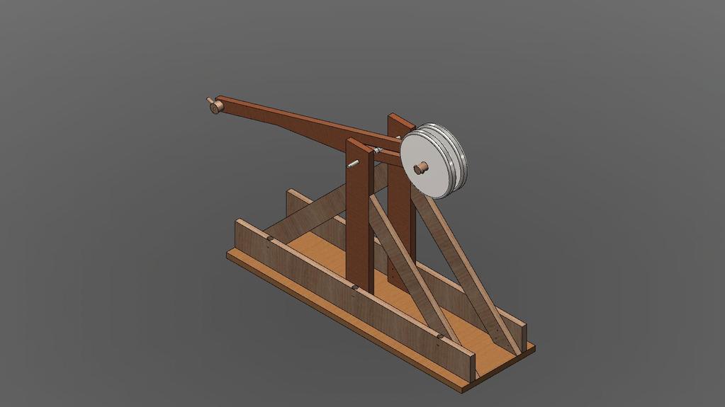
 Trebuchet Trebuchet Parts List and Overview The trebuchet pictured above is armed and ready to throw an object. Pulling the pin out of the trigger allows the counterweight to fall. The long end of the
It is highly recommended that you use a thread lock compound such as Loctite brand on all threads to keep them from vibrating loose.
 Installation instructions for FC12 Forward Controls for Kawasaki Vulcan 750 It is highly recommended that you use a thread lock compound such as Loctite brand on all threads to keep them from vibrating
Lumber Smith. Assembly Manual. If you are having problems assembling the saw and need assistance, please contact us at:
 Lumber Smith Assembly Manual If you are having problems assembling the saw and need assistance, please contact us at: 804-577-7398 info@lumbersmith.com 1 Step 1 Safety Carefully read the Owners Manual.
INSPECTION AND CORRECTION OF BELLHOUSING TO CRANKSHAFT ALIGNMENT
 INSPECTION AND CORRECTION OF BELLHOUSING TO CRANKSHAFT ALIGNMENT BACKGROUND Proper alignment of the transmission input shaft to the crankshaft centerline is required in order to achieve the best results
Electric Skein Winder
 Electric Skein Winder Assembly and Use Package Contents 1 - Triangular Body (w/ motor) 1 - Cross Arm 1 - Left Foot (w/ yarn guide) 1 - Right Foot 1 - Adjustable Finger (w/ yarn clip) 3 - Adjustable Fingers
SAFETY INSTRUCTIONS. Wear protective clothing, including safety glasses and steel toe boots.
 SAFETY INSTRUCTIONS Wear protective clothing, including safety glasses and steel toe boots. DO NOT allow loose clothing or long hair near machine operations. Keep work site and machine clean. Use brush
Warnings. Description. Prior to Installation Tools Needed
 Warnings Failure to act in accordance with the following may result in death or personal injury. The JT Strong Arm Stabilizer System is intended to eliminate chassis movement in travel trailers and fifth
Desktop Trebuchet Kit Assembly Instructions
 Desktop Trebuchet Kit Assembly Instructions Contents of package (drawings are not to scale for clarity, parts that have duplicates are indicated with total number of that part to be found, example: 2X
PORTABLE ADJUSTABLE BASKETBALL SYSTEM
 Instruction Manual PORTABLE ADJUSTABLE BASKETBALL SYSTEM P A R T S L I S T 5 1/2 and 8 safe play clearance Item Qty Description Item Qty Description A 1 Portable Base Assembly M 4 1/2 Lock Nut B 2 Front
The Useless Machine. Parts Only - Build Guide v0001
 TM The Useless Machine Parts Only - Build Guide v0001 For the best outcome, follow each step in order. We recommend reading this guide entirely before you get started. Tools required: One phillips screwdriver,
LIGHT BEAM ANTENNA MaxRange Antenna Series Assembly Instructions MaxRange Plus Digital / High Definition Television Antennas
 LIGHT BEAM ANTENNA MaxRange Antenna Series Assembly Instructions MaxRange Plus Digital / High Definition Television Antennas Assembly Instructions 1 MaxRange Plus Antenna These instructions will lead you
Nancy s Knit Knacks LLC 4 Yard Option Upgrade Kit Assembly Instructions and User Manual
 Nancy s Knit Knacks LLC 4 Yard Option Upgrade Kit Assembly Instructions and User Manual Thank you for purchasing our 4 Yard Option (4YO) Upgrade Kit. To install this upgrade you are simply going to assemble
RTI TECHNOLOGIES, INC.
 RTI TECHNOLOGIES, INC. BRC500 & BRC550 Arbor/Spindle Mechanism Adjustment & Service Technical Instructions The arbor/spindle mechanism of the BRC500/550 is designed to be robust for long life. Occasionally
400A 40113V, 401A 40120V, & 401AL 40120VL ALUMINUM VERTICAL 4000 LB LIFT INCLUDES SCREW LEG ASSEMBLY INSTRUCTIONS
 12/11/07 PAGE 1 OF 12 400A 40113V, 401A 40120V, & 401AL 40120VL ALUMINUM VERTICAL 4000 LB LIFT INCLUDES SCREW LEG ASSEMBLY INSTRUCTIONS Thank you for purchasing our product! *Please read these instructions
GlideRite Retractable Cover System For Hot Spot Spas (SE & SLX only)
") List of Contents Quantity Description 12 #10 x 1 ½ Flat Head Phillips Screw (see pg. 2) 2 #10 x ½ Pan Head Phillips Screw (see pg. 2) 8 ¼ x 2 ½ Lag Bolt (see pg. 2) 7 ¼ 20 x 5 / 8 Hex Head Bolt (see pg.
List of Contents Quantity Description 12 #10 x 1 ½ Flat Head Phillips Screw (see pg. 2) 2 #10 x ½ Pan Head Phillips Screw (see pg. 2) 8 ¼ x 2 ½ Lag Bolt (see pg. 2) 7 ¼ 20 x 5 / 8 Hex Head Bolt (see pg.
Giraud Tool Company, Inc.
 Motor Upgrade for Gracey Trimmer This package is intended to allow the user to upgrade their Gracey trimmer with a higher rpm motor and convenience features not found in the production offering. This upgrade
TRAILMATE METEOR ASSEMBLY MANUAL
 TRAILMATE METEOR ASSEMBLY MANUAL The Trailmate Meteor recumbent has been designed for easy assembly. This means more time to enjoy the smooth ride with single speed, 3 speed coaster brake and 21 speed
S48-L12-SC AND G48-L12-GC STEEL PORTA-DOCK S82 SC 6 X 12 PLATFORM AND G82 GC 6 X 12 PLATFORM
 PAGE 1 OF 6 PORTA-DOCK, INC. S48-L12-SC AND G48-L12-GC STEEL PORTA-DOCK S82 SC 6 X 12 PLATFORM AND G82 GC 6 X 12 PLATFORM Thank you for purchasing our product! *Please read these instructions and follow
Thank you for purchasing our product! *Please read these instructions and follow them step by step.*
 07/07/08.rev1 PAGE 1 OF 11 601AL VERTICAL 60120VL LIFT W/CHAIN DRIVE WINCH Thank you for purchasing our product! *Please read these instructions and follow them step by step.* Step 1. Separate and group
GlideRite Retractable Cover System For HotSpring & Tiger River Spas (except Classic & pre-2000 Landmark Spas)
") List of Contents Quantity Description 12 #10 x 1 ½ Flat Head Phillips Screw (see pg. 2) 2 #10 x ½ Pan Head Phillips Screw (see pg. 2) 8 ¼ x 2 ½ Lag Bolt (see pg. 2) 7 ¼ 20 x 5 / 8 Hex Head Bolt (see pg.
List of Contents Quantity Description 12 #10 x 1 ½ Flat Head Phillips Screw (see pg. 2) 2 #10 x ½ Pan Head Phillips Screw (see pg. 2) 8 ¼ x 2 ½ Lag Bolt (see pg. 2) 7 ¼ 20 x 5 / 8 Hex Head Bolt (see pg.
For additional assistance call
 The following pages will help guide you through the process of assembling your new 48 custom prize wheel. Choose an assembly area with plenty of room to lay your pieces on the floor and also a bench or
Using the RhAT II Universal
 Using the RhAT II Universal To use the Original RhAT Tools, the main shaft of the machine had to be rotated to the setting position, either mechanically or electronically, while the needle bar was disengaged
Item # Thanks for shopping with Improvements!
 Thanks for shopping with Improvements! Hampshire -Door Cabinet Item #5505 To order, call -800-64- West Chester, OH 45069 Made in China PR-6 If you have questions regarding this product, call -800-64- Mon.-Fri.
PORTA-DOCK, INC. AP17 APD DS 4 X 16 T12 AW17 CPD DS 4 X 16 T12
 Page 1 of 7 PORTA-DOCK, INC. AP17 APD DS 4 X 16 T12 AW17 CPD DS 4 X 16 T12 *For Beige Decking Add the Letter B to Model* Thank you for purchasing out product! *Please read these instructions and follow
CONTENTS TOOL LIST U P S I D E I N N O V A T I O N S, L L C RAMP AND STEP SYSTEM ASSEMBLY INSTRUCTIONS. Revised: June 2013
 U P S I D E I N N O V A T I O N S, L L C RAMP AND STEP SYSTEM ASSEMBLY INSTRUCTIONS TOOL LIST Required Tools: - Reciprocating Saw with Metal Cutting Blade - Drill - 7/16 Drill Bit for Metal Drilling -
Deck Mount Installation with Bench
 Deck Mount Installation with Bench 1. Mark track with square. 2. Cut tracks with saw. 3. Drill ¼ hole (if needed.) 4. Countersink track. 5. Countersink all track 6. File all track ends. ends. 7. Lay out
WPS crew Doors Installation instructions
 WPS-132-133 crew Doors Installation instructions ORDER OF INSTALLATION FOR A COMPLETE ENCLOSURE OF A CREW WPS (Weather Protection System) IS AS FOLLOWS: 1. Heater 2. Rear Thresholds - Right Hand & Left
200A FLB VERTICAL 22113V LIFT W/CHAIN DRIVE WINCH
 PG. 1 OF 11 PORTA-DOCK, INC. 200A FLB VERTICAL 22113V LIFT W/CHAIN DRIVE WINCH STEP 1. Separate and group like parts and fasteners together. Locate the winch side member with the longer upright tube and
Catapult Engineering
 With support from Oxfordshire County Council, Science Oxford is pleased to present; Catapult Engineering The Physics of Siege Weapons STEM Club Resource Pack Introduction: Catapult engineering involves
A59 APD & A86 CPD 5'X 16' SW ALUMINUM PORTA-DOCK
 Page 1 of 5 PORTA-DOCK, INC. A59 APD & A86 CPD 5'X 16' SW ALUMINUM PORTA-DOCK *For Beige Decking Add the Letter B to model* Thank you for purchasing our product! *Please read these instructions and follow
Depending on the size you ordered you will have either 5 Foot sections which will build the 10 Foot frame or 6 Foot sections which will build the 12
 XL Quilting Frame 1 Depending on the size you ordered you will have either 5 Foot sections which will build the 10 Foot frame or 6 Foot sections which will build the 12 Foot frame Printed 2 June 2014 Updated
Gared Pro-S Portable Backstop
 Models: 9616 & 9618 Installation, Operation and Maintenance Instructions Please read all instructions before attempting installation or operation of these units SAVE THESE INSTRUCTIONS FOR FUTURE USE PUBLICATION
STEP 1 : DESTROYER FRONT BUMPER INSTALL GATHER YOUR TOOLS AND LAY OUT YOUR PARTS... *shorty bumper to show hardware* Tools Required:
 DESTROYER FRONT BUMPER INSTALL JL STEP 1 : GATHER YOUR TOOLS AND LAY OUT YOUR PARTS... Tools Required: - Utility knife - 11/16 Deep socket - Ratchet - 11/16 Crescent wrench - Ratchet Extension - 1/4 socket
Football Goal Posts MODEL SERIES: FGP400 and FGP600 series
 Football Goal Posts MODEL SERIES: FGP400 and FGP600 series Installation and Maintenance Instructions Please read all instructions before attempting installation of these units SAVE THESE INSTRUCTIONS FOR
INSTALLATION OF WELLS SUPER QUICK CHUCK LEFT HAND ON RED WING LATHE
 DENTAL, INC. TECHNICAL BULLETIN Q824-022510 5860 FLYNN CREEK ROAD READ ALL INSTRUCTIONS P.O. BOX 106 BEFORE PROCEEDING COMPTCHE, CALIFORNIA, U.S.A. 95427 SAVE THIS FOR FUTURE REFERENCE www.wellsdental.com
Wind Pump Construction
 What Will You Need? Page 1 The following components can be found in your kit, and are needed to build one wind pump: 50 Tooth Gear* 40 Tooth Gear* 20 Tooth Gear* 10 Tooth Gear* Wheel Hub 300mm (~12in)
Replacing the build plate clamps
 Repair manual Replacing the build plate clamps Instructions The build plate clamps hold the glass plate in place on the heated bed. There are two fixed in place at the back of the heated bed and two at
American Morse Equipment
 American Morse Equipment Thank you for purchasing an American Morse Porta Paddle-II Kit. We redesigned the original Porta Paddle for ease of assembly & provide all parts finished and ready for assembly,
The Phoenix. Professional Quilting Frame. Copyright January 1, 2016 Jim M. Bagley, GraceWood, Inc (Reproduction Prohibited) Version 2.
 Version 2.") The Phoenix Professional Quilting Frame Copyright January 1, 2016 Jim M. Bagley, GraceWood, Inc (Reproduction Prohibited) Version 2.1 1 The Phoenix Professional Quilting Frame Parts List Box 1...3 Box
The Phoenix Professional Quilting Frame Copyright January 1, 2016 Jim M. Bagley, GraceWood, Inc (Reproduction Prohibited) Version 2.1 1 The Phoenix Professional Quilting Frame Parts List Box 1...3 Box
Playground Assembly Instructions
 Before You Begin Playground Assembly Instructions Locate the playground set on firm, level ground. Assemble the playground on or close to its permanent location Two people are recommended to assemble the
Thank you for purchasing out product! *Please read these instructions and follow them step by step. *
 Page 1 of 7 AD17 AA DS 4 X 16 T12 Thank you for purchasing out product! *Please read these instructions and follow them step by step. * STEP 1. Slide two support posts (REF. # 24) into the two outside
Installation instructions for FC14S Forward Controls for Shadow ACE and Aero 1100
 Installation instructions for FC14S Forward Controls for Shadow ACE and Aero 1100 It is highly recommended that you use a thread lock compound such as Loctite brand on all threads to keep them from vibrating
DATE: January, 01, 2011 AUTHOR: Craig Macomber TOPIC: Making and operating a model onager
 DATE: January, 01, 2011 AUTHOR: Craig Macomber TOPIC: Making and operating a model onager INTRODUCTION This guide will walk you through the construction and operation of a hand held scale Roman Onager,
EPPA2-KIT DUAL MONITOR ARM CONVERSION
 EPPA2-KIT DUAL MONITOR ARM CONVERSION EPPA2-KIT Rev A 10/17 Model EPPA2-KIT-XXX ASSEMBLY AND ADJUSTMENT EPPA2-KIT PARTS AND TOOLS PLEASE REVIEW these instructions before beginning the assembly and adjustment
ABM International, Inc. Navigator Assembly Manual
 ABM International, Inc. 1 1.0: Parts List Tablet (Qty. 1) Tablet mount (Qty. 1) NOTE: Mount may appear and operate different then image below Control Box (Qty. 1) Motor Power Supply (Qty. 1) 2 X-axis motor
model tsa-sa48 Sliding Crosscut Table installation guide
 model tsa-sa48 Sliding Crosscut Table installation guide A Note About Color Variations Among Anodized Aluminum Components Congratulations on the purchase of this SawStop Sliding Crosscut Table. We at SawStop
SwingSafe Swing-Away Mailbox Support Diagram
 SwingSafe Swing-Away Mailbox Support Diagram Wood Mounting Plates Top Arm (B) Muffler Clamps (A) Carriage Bolts and Nuts Bottom Arm 4-Foot U-Channel Post USPS Recommended 42-44 Height Ground Slope Hex
Replacing the Reciprocator on the SWF Compact Series Machine (601C and 1201C)
") Follow the instructions below to replace the reciprocator in the SWF Compact series machines. The tools required can be found in the tool kit that came with the machine. Preparation 1. First, place the
Follow the instructions below to replace the reciprocator in the SWF Compact series machines. The tools required can be found in the tool kit that came with the machine. Preparation 1. First, place the
Topo Freestanding Applications - Private Office
 4 3 2 Topo Freestanding Applications - Private Office Combo Wrench If you have a problem, question, or request, call your local dealer, or Coalesse at 1.800.627.6770 Or visit our website: www.coalesse.com
Customer Notice: Congratulations again on your SawStop purchase, and thank you! -SawStop Tualatin, OR
 Customer Notice: Congratulations on the purchase of this Sliding Crosscut Attachment. As the owner of a SawStop saw, you are familiar with our high standards for quality, fit and finish. Different from
User Instructions Multiline Otter Scoreboard Caddy Assembly
 List of parts: User Instructions Multiline Otter Scoreboard Caddy Assembly Single Caddy Double Caddy 1 1 Base assembly with attached wheels 2 4 1 1 2 4 4 8 10 20 12 Uprights (60 or 74 aluminum extrusion)
Hollywood Swing Away 2 and 4 Bike Racks Assembly and Installation Guide
 Hollywood Swing Away 2 and 4 Bike Racks Assembly and Installation Guide Tools Required: two adjustable wrenches, pliers, ¾ socket wrench recommended Note: please do assembly near your vehicle as you Can
The Useless Machine. DIY Soldering Edition. Instruction Guide v0004
 The Useless Machine DIY Soldering Edition Instruction Guide v0004 TM For the best outcome, follow each step in order. We recommend reading this guide entirely before you get started. Tools required: Soldering
FABA. Installation Instructions. Conductor Bar System. Publication #FABA-03 3/1/04 Part Number: Copyright 2004 Electromotive Systems
 FABA Conductor Bar System Installation Instructions Publication #FABA-03 3/1/04 Part Number: 005-1062 Copyright 2004 Electromotive Systems 1S 100 Z Installation Instructions Contents: Basic Diagram - -
Installation Instructions for Vista Air Vertically Folding Walls
 Installation Instructions for Vista Air Vertically Folding Walls Use these instructions in conjunction with your shop drawings to see the specifics that are particular to the model you are installing.
Installation Instructions
 Installation Instructions Ceiling Mount Bracket for DLP Based Projectors (for High Ceilings) Model No. ET-PKD100H Contents Important Safety Notice.................. 2 For DLP Based Projector: PT-D10000
LCD MONITOR/TV WALL MOUNT
 INSTALLATION INSTRUCTIONS LCD MONITOR/TV WALL MOUNT DUAL DESK CLAMP (RFCD-110) S CAUTION CAUTION A alerts you to the possibility of serious injury or death if you do not follow the instructions. A CAUTION
LANDING GEAR. 1. Fit landing gear into slots on bottom of fuselage.
 LANDING GEAR 1. Fit landing gear into slots on bottom of fuselage. 4. Use channel-lock pliers to press blind nuts into position (note: drilled hole should be slightly smaller than shaft of blind nut for
7878 K940. Checkpoint Antenna. Kit Instructions. Issue B
 7878 K940 Checkpoint Antenna Kit Instructions Issue B Revision Record Issue Date Remarks A July 7, 2009 First issue B Nov2013 Revised the Checkpoint installation procedures for 7878 and 7874 scanners Added
INSTALLATION INSTRUCTIONS
 INSTALLATION INSTRUCTIONS Universal Low Profile Flat Mount Model: U.S. Toll Free: 1-866-752-6271 Outside N. America: 1-503-748-5799 E-mail: ts@planar.com FRANCE Phone: +33 5 6378 3810 E-mail: emeats@planar.com
Model #SH & CH SH Pine CH Naturaline
 Model #SH304-101 & CH304-101 Assembly Manual SH304-101 Pine CH304-101 Naturaline Component Parts A 2 ea. Angled Rail - 2 x 4 x 107-1/8" B 1 ea. Center Angled Rail - 2 x 4 x 107-1/8" C 9 ea. Rock Board
TYPHOON ASSEMBLY AND INSTALLATION INSTRUCTIONS
 TYPHOON ASSEMBLY AND INSTALLATION INSTRUCTIONS CORPORATE HEADQUARTERS WESTERN SALES AND MANUFACTURING PLANT P.O. Box 400 1017 SW Berg Parkway Canby, Oregon 97013 Phone: (503) 266-2231 Fax: (503) 266-4334
ROMAN AND. Roller Lift System Continuous Cord Loop GETTING STARTED BRACKET INFORMATION INSIDE MOUNT. A few simple tools are required:
 ROMAN AND WOVEN WOOD SHADES Roller Lift System Continuous Cord Loop GETTING STARTED BRACKET INFORMATION A few simple tools are required: The brackets you received with your product are REQUIRED for proper
INSTALLATION INSTRUCTIONS
 INSTALLATION INSTRUCTIONS PROTRAXX OVAL STEP BAR APPLICATION: 2009-2017 Dodge Ram 1500 Crew/Quad Cab 2010-2017 Dodge Ram 2500/500 Crew Cab PART NUMBER: 21-550, 21-555, 21-50, 21-55 AUTOMOTIVE PRODUCTS,
100mm (3in) Slide Stop Cut to 6mm (1/4in) Sections. Quantity: mm (10in) Skewers Quanity: 10. Material to Lift. Material for Blades.
 Slide Stop Cut to 6mm (1/4in) Sections. Quantity: mm (10in) Skewers Quanity: 10. Material to Lift. Material for Blades.") Wind Lift Page 1 The Activity This guide will take you through the process of creating a wind powered lift. You ll start by creating the stand. The lift mechanism, hub and blades are then added. Before
Wind Lift Page 1 The Activity This guide will take you through the process of creating a wind powered lift. You ll start by creating the stand. The lift mechanism, hub and blades are then added. Before
Replacing the build plate clamps
 Repair manual Replacing the build plate clamps Instructions The build plate clamps hold the glass plate in place on the heated bed. There are two fixed in place at the back of the heated bed and two at
Sliding Crosscut Table installation guide
 Sliding Crosscut Table installation guide model tsa-sa48 A Note About Color Variations Among Anodized Aluminum Components Congratulations on the purchase of this SawStop Sliding Crosscut Table. We at SawStop
METAL BENDER OPERATING & MAINTENANCE INSTRUCTIONS Model Nos: CCB1 & CCB2 Part Nos: & CCB2 CCB1
 METAL BENDER Model Nos: CCB1 & CCB2 Part Nos: 7630073 & 7630074 CCB2 CCB1 OPERATING & MAINTENANCE INSTRUCTIONS 1206 1 The Compact Bender allows you to economically make a variety of bends in flat, square,
Installation Instruction
 Tools Needed for Assembly Stud finder (for wood stud wall) Pencil Mark Electric drill Wood Stud Wall Installation Step 1. Locate the Wood Studs Installation Instruction Drill bit (for wood stud wall) Masonry
Universal Projector Ceiling Mount Model: DPM-45
 Universal Projector Ceiling Mount Model: DPM-45 Instruction Manual Images may different from actual product Disclaimer It is Dyconn s intention to have all the correct information represented within this
BEAST THE. Tube and Pipe Notcher Operating Instructions. Notches In Bends Straight Notches. Angled Notches. Offset Notches
 Copyright (c) 2007 J D SQUARED INC. www.jd2.com THE BEAST Tube and Pipe Notcher Operating Instructions Notches In Bends Straight Notches Angled Notches PATENT PENDING Offset Notches Assembly After unpacking
For Barrel Tapers. Installation and Operating Instructions For use with small combination belt & disk sanders. Assembled Taper Tool
 Tim s Taper Tool For Barrel Tapers Installation and Operating Instructions For use with small combination belt & disk sanders Assembled Taper Tool Your taper tool is capable of making barrel tapered shafts.
Clocking a TD-04 Turbo Compressor Housing. Appendix A : AWIC Silicone and Tubing Fitting
 Clocking a TD-04 Turbo Compressor Housing Appendix A : AWIC Silicone and Tubing Fitting Revision A: 7-13-2015 Tools: Metric Sockets (10, 12, 14, 17mm) 5mm Hex Key Large Internal Snap Ring Pliers 3/8 Socket
ULTRAFEED INDUSTRIAL TABLE PACKAGES Set-up Guide for #120931, # & #121091
 120932*1 Instructions for Sailrite Ultrafeed Industrial Table Packages ULTRFEE INUSTRIL TBLE PKGES Set-up Guide for #120931, #120934 & #121091 2 Ultrafeed Industrial Table Packages The Ultrafeed Industrial
a.k.a. casegoods instructions
 a.k.a. casegoods instructions a a.k.a. workwall installation IMPORTANT NOTES Failure to install product according to installation instruction will result in loss of warranty. Tools required for assembly
Work Space Set-up. Slats will level the pipe during bending and help minimize twisting of the bow.
 Work Space Set-up Affix pipe bender to end of working surface Slats will level the pipe during bending and help minimize twisting of the bow. Make the slat height equal the distance from your work surface
Woodline USA Woodline Spacer Fence System
 Woodline USA Woodline Spacer Fence System MADE IN THE USA Includes: (1) ¼ Spacer Fence (1) 3/8 Spacer Fence (1) ½ Spacer Fence (1) Hardware Package (1) 3 Piece Brass bar set (2) Setup Blocks Visit Us Online
Castle Frame Assembly Table AT-8. Diagnostics Manual. Castle, Inc. Petaluma, CA
 Castle Frame Assembly Table AT-8 Diagnostics Manual Castle, Inc. Petaluma, CA 800-282-8338 Solutions Index Adjusting the Tabletop.. 8.01 Adjusting the Fence... 8.02 Aligning the Arm... 8.10 Adjusting Bracket..
Wagon Vise Retrofit Installation Instructions. American Craft Woodworks. Wagon Vise
 Wagon Vise Retrofit Installation Instructions American Craft Woodworks Wagon Vise Wagon Vise Retrofit Installation Instructions 2 Retrofit Installation Instructions Before you get started, please read
6' Wide Premium Greenhouse Benches
 6' Wide Premium Greenhouse Benches Premium Greenhouse Bench with Rolling Top 2015 FarmTek All Rights Reserved. Reproduction is prohibited without permission. STK# DIMENSIONS 112416R6X08 6' W x 3' H x 8'
Strata. urniture. Adriana Instructions. Parts in the Arm Box: Parts in the Body Box: Watch our assembly videos at
 1A Watch our assembly videos at www.strataf.com/videos Parts in the Arm Box: Arm - Outside View Arm - Inside View 1B Parts in the Body Box: Back Deck x 1 Seat Deck x 1 with the Feet attached Back Panel
INSTALLATION INSTRUCTIONS
 Do not attempt to install this product on any vehicle other than the one it is designed for and listed above! Parts List 10 3/8 X 1 1/4 Hex Bolt 10 3/8 Lock Washer 4 3/8 Hex Nut 4 3/8 Flat Washer 2 3169)
Gared Pro Portable Backstop
 Models: 5016, 5017, & 5018 Installation, Operation and Maintenance Instructions Please read all instructions before attempting installation or operation of these units PUBLICATION NO. 551754436 SAVE THESE
The Archer Bow Press OPERATING INSTRUCTIONS Partridge Woods Elk Rapids, MI
 The Archer Bow Press OPERATING INSTRUCTIONS 8203 Partridge Woods Elk Rapids, MI 49629 www.bowforcearchery.com 1 MAINTENANCE AND FINE TUNING Horizontal Pulling Bar The Horizontal Pulling Bar has a break-in
6' Wide Premium Greenhouse Benches
 6' Wide Premium Greenhouse Benches Premium Greenhouse Bench with Stationary Top 2015 FarmTek All Rights Reserved. Reproduction is prohibited without permission. STK# DIMENSIONS 112416S6X08 6' W x 3' H
mila-wall (Series100) General Operating Instructions page 1 of 15
 General Operating Instructions page 1 of 15") mila-wall (Series100) General Operating Instructions page 1 of 15 Step #1: Before setting up walls, lower adjustable leveling feet on each panel approximately 1". This will allow access to the threaded
mila-wall (Series100) General Operating Instructions page 1 of 15 Step #1: Before setting up walls, lower adjustable leveling feet on each panel approximately 1". This will allow access to the threaded
INSTALL INSTRUCTIONS WELCOME TO THE NEWAGE PERFORMANCE CABINETRY SERIES NEWAGE STEEL WELDED CABINETRY
 NEWAGE STEEL WELDED CABINETRY WELCOME TO THE NEWAGE PERFORMANCE CABINETRY SERIES ALL CABINETS MUST BE MOUNTED TO STUDS ON A SECURE WALL, AS PER THESE INSTRUCTIONS. FAILURE TO DO SO MAY RESULT IN SERIOUS
TRAMPOLINE A SSEMBLY I N S T RUC T I ONS
 OVAL TRAMPOLINE A SSEMBLY I N S T RUC T I ONS Safety Tips At Oz Trampolines, we are passionate about your family s safety when using our trampolines and accessories. We have put together a list of safety
Continuum Frame Assembly Instructions
 Continuum Frame Assembly Instructions Copyright January 1, 2017 Jim M. Bagley, GraceWood, Inc (Reproduction Prohibited) Version 2.2 Table of Contents Continuum Frame Table of Contents... i Warranty...ii
ASHFORD TABLE LOOM - FOUR SHAFT 410/610/800mm 16/24/32in
 INSTRUCTIONS ASHFORD TABLE LOOM - FOUR SHAFT 410/610/800mm 16/4/3in Ashford Handicrafts Ltd. Factory and Showroom: 415 West Street, PO Box 474, Ashburton, New Zealand Telephone 64 3 308 9087 Facsimile
INSTALLATION INSTRUCTIONS
 INSTALLATION INSTRUCTIONS Universal Low Profile Tilt Mount Model: U.S. Toll Free: 1-866-752-6271 Outside N. America: 1-503-748-5799 E-mail: ts@planar.com FRANCE Phone: +33 5 6378 3810 E-mail: emeats@planar.com
INSTALLATION INSTRUCTIONS HEAVY DUTY TILT WALL MOUNT Model: PPH-2000
 INSTALLATION INSTRUCTIONS HEAVY DUTY TILT WALL MOUNT Model: PPH-2000 Specifications: Accomodates Akira and Orion 84" displays without interface bracket; accomodates other large flat panel displays with
SPINKS BIN SCALES INSTRUCTIONS/OPERATIONS MANUAL FOR SCALE MODELS: ,000 lb ,000 lb ,268 kg ,500 kg.
 SPINKS BIN SCALES INSTRUCTIONS/OPERATIONS MANUAL FOR SCALE MODELS: 415442 5,000 lb. 415473 10,000 lb. 415520 2,268 kg. 415498 4,500 kg. FEBRUARY, 2000 MANUAL NO. 000250 TABLE OF CONTENTS CONCRETE PLACEMENT...Page
OPERATOR'S MANUAL RULES FOR SAFE OPERATION
 OPERATOR'S MANUAL #4950300 ROUTER AND JIG SAW MOUNTING KIT (FOR USE WITH THE BT3000 TABLE SAW) CONGRATULATIONS AND THANK YOU FOR BUYING THIS RYOBI ROUTER AND JIG SAW MOUNTING KIT. Your new #4950300 Router
High performance 90mm fiberglass jet
 High performance 90mm fiberglass jet Assembly manual For intermediate and advanced fliers only! Specs Wingspan: 1255mm Fuselage length: 1250mm Flying weight: 2600-3000g Wing area: 22.6 dm² Wing loading:
PFW 6851 Display Wall Mount, Turn & Tilt 80 kg INSTALLATION INSTRUCTIONS
 Display Wall Mount, Turn & Tilt 80 kg INSTALLATION INSTRUCTIONS 9531-007-Z00-01 Table of Contents Warning Statements 2 Parts List 3 Installation Tools 3 Wood Stud Installation 5 Concrete Surface Installation
CV1B Sliding Table Installation and Setup Guide
 CV1B Sliding Table Installation and Setup Guide Tech Mark, Inc 7901 Industry Drive North Little Rock, AR 72117 tel (501) 945-9393 fax (501) 945-0312 www.tech-mark.com email: info@tech-mark.com The CV1B
TOOL LIST FOR TAILGATE HIDDEN LATCH & LINK ASSY FOR FORD FLARESIDE TRUCKS
 TOOL LIST FOR TAILGATE HIDDEN LATCH & LINK ASSY FOR 53-87 FORD FLARESIDE TRUCKS Vise Grip Clamps C-clamps Sharpie Marker Ball Peen Hammer Center Punch 3/8 or 1/2 Drill 5/32, 7/32, 9/32, and 3/8 Drill Bits
Tin Lizzie 18 Assembly Instructions
 Tin Lizzie 18 Assembly Instructions Revision: 07/29/16 Table of Contents Aides 3 Before You Begin 5 Aides 5 Tools 6 Perfect Stitch Parts 2 12 Modify the Machine 12 Prepare Drill Templates 12 Front Display
Installation Instructions Kit, Base Rail Bracket Part # 31413
 Installation Instructions Kit, Base Rail Bracket Part # 31413 Dealer / Installer: Provide a copy of these Instructions to the end user of this product. These Instructions provide important operating and