GSA-16, GSA-37 & GSA-80
|
|
|
- Reginald Matthews
- 6 years ago
- Views:
Transcription


1 Review of GSA-16, GSA-37 & GSA-80 Gauges Manufactured by Flight Illusion Intro During my ride around flightsim hardware I have had the chance of testing and reviewing numerous modules and parts that all contributed greatly to the general flightsim experience. However one thing that I had not tested was real time, old age analogue gauges since most cockpit components today are from the modern age of aviation where the general cockpit layout has changed to be a glass cockpit etc. Today the old age gauges are mostly used as standby gauges and in some cockpit layouts the old age gauges has completely been removed and replaced by huge TFT screens. I surely like the modern age cockpits but I find the old age gauge to be very nostalgic and they reminds me of the time where I flew smaller aircrafts myself. I have had the chance of taking a look at 3 gauges from Flight Illusion which are the basic instruments but at different levels of complexity and age. The first gauge is the GSA-37 Attitude indicator gauge with central pitch which is the original old age gauge. The second gauge is the GSA-16 Altitude indicator gauge which is a combo gauge of the old age altimeter and newer LED display technology. The third and last gauge is a modern age gauge, the GSA-80 which is a replica of the IAS/Mach gauge found in the famous Lockheed Martin F-16 Fighting Falcon. To get all gauges to work I have also purchased the GSA-55PS which is not a gauge but a central interface board (PCB) including the power supply, so that I can hock up the gauges to my computer.
2 Purchase, Delivery & Packing I purchased these units directly from Flight Illusion who is located in The Netherlands well the R&D and the production are located there and the sales department is located in Belgium. The purchase went with ease because the website is very user friendly meaning that you just add the unit you like to your basket and when finished just click to the check-out. Just a heads-up these units are normally for professional usage for real pilot training simulators and due to the high quality and complexity of these gauges you might find the price range to be very high. However I had a secondary mission with these gauges and that was to find out how much they could increase my flightsim experience when being added to my home cockpit setup. After the purchase was completed I was informed that the gauges would enter production and be delivered directly when the production had completed. What I wasn t aware of was that the production lead-time was actually 3 weeks this is of course not a problem but that could have been nice information to have received prior to the purchase. This is just because when I order some software or hardware I really want it urgently and now I had to wait for 3 weeks. That said, the production was on schedule and the units were all sent in due time and the delivery only took 36 hours from the production plant in The Netherlands to my office in Denmark. This was quick and easy and I really like the fact that I was able to track and trace the consignment all the way. The consignment was delivered to a SwipBox which gave me the opportunity to collect the consignment myself outside office hours. This was important to me because at the arrival I was not at the office. The packing of the units were good and consisted of a special made cardboard support around the units which held them firmly in place and then this combined unit was covered with some tight fitted wrapping plastic/film so that the units were 100% fixed. This combined unit was then put into a hard cardboard box which again features support so that the units were all fixed and unable to move during transport.

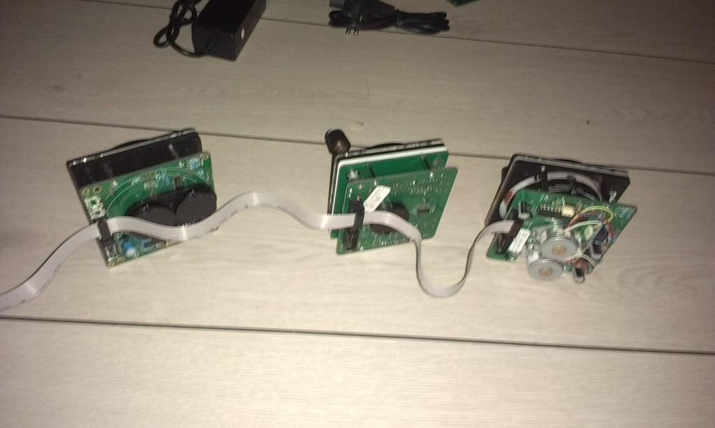
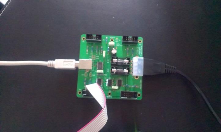
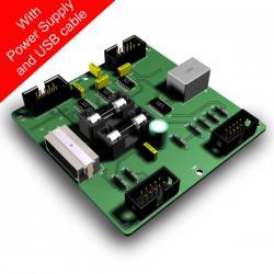
3 Parts included I purchased a set of gauges including the GSA-55PS which is the interface unit (PCB) including power supply, so the complete consignment included both the 3x gauges, the PCB, the power supply but also a custom made connection cable so that all gauges could fit on that one string and did not need each their own. This was a really nice discovery because that helps keep my wiring complexity in my home cockpit setup to a minimum. Only thing not included was the USB cable from the PCB to the computer even though it is stated at Flight Illusions website that it should be included however the USB cable is just a standard connection USB cable as normally used for other flightsim modules etc. so that was not an issue. The power supply is a direct plug into the wall socket and then into a converter that converts the 220V down to the voltage used in the PCB which is 5/12 volts where the 5 volts is to drive the stepper motors and the 12 volts is to power the lights. Well the conversion is to 12 volts and the PCB takes care of the rest. The connection wire is connected to the PCB using just one of the four connectors and then each gauge will get each a connector so that the complete setup is just by using that one string. If I were to max out the PCB then I could connect 16 gauges on each string making the total number of gauges to be connected using this single PCB, at total of 64 gauges that is quite impressive!

4 Software Before being able to use the gauges you will need to install some software. All software can be downloaded from Flight Illusions website and is of course free of charge. What you need is a USBto-COM driver which is an external download but the link to it you can find on Flight Illusions website. I found that I already had a USB-to-COM driver so I did not have to do that download. The second piece of software needed is the software created by Flight Illusion which enables you to control and setup the gauges etc. This software is downloaded directly at Flight Illusions website and here you can select specific flightsim versions as e.g. FS9, FSX, P3D, X-Plane and IL-2. This review is done based on FSX so I of course downloaded the FSX version. The download was quick due to the fact that the size of the file was limited and the connection to Flight Illusions download server was really good. The installation was also very easy, just activating the included installation wizard and after a few seconds the software was perfectly installed and ready for use. What the software does is to provide the interface with the flightsim and the gauges using FSUPIC and also enables the simmer to customize his/hers setup. E.g. in the below image I have created my own setup and named it Ray.cfg to see the actual configuration I entered the Configuration button. Fig:1

5 The configuration is as shown here below (Fig:2) featuring all the 3 gauges that I have included on my string and as example I have included Fig:3 which shows the specifics for the altimeter gauge GSA-16. What you can see is the ID number for each gauge which is defined automatically but which is also editable so that I could re-number the gauges to be 1, 2 and 3 if I wanted to. Also is a description of the device, a model number, a version number, both the first and second function and the connection status. The reason for why the status is set as Unknown is simply because I had not connected it to FSX yet. You can also see that the ID 101 = the Digital/Analogue Altimeter does not feature a second function which is correct because it only feature the altitude function, where e.g. the ID 103 Attitude indicator features both a pitch function and a bank function etc. Fig:2

6 In Fig:3 here below I have entered the specifics for the altimeter which opens up a control panel where I can set various values, change the ID, the function, modes, backlights etc. The other two gauges have similar control panels that of course are customized to their unique specialties. When setup as wanted I just clicked the button Apply/Assign and the Ray.cfg that I had created was/is automatically updated. Fig:3


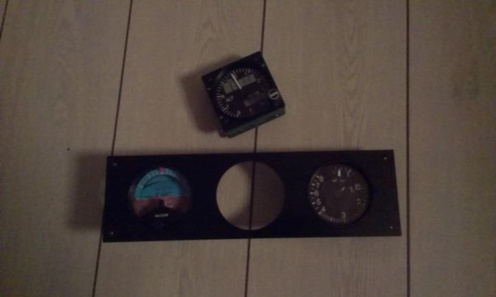
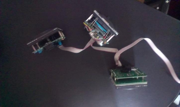
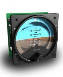
7 GSA-37 Attitude indicator blue/brown with central pitch indicator button The first gauge that I tested was the GSA-37 which is an attitude indicator including the central pitch indicator button. Flight Illusion has several different attitude indicator gauges and the reason for why I selected this one, was simply because I wanted a gauge including the pitch function and the blue/brown color reminded me of the cockpit of my Diamond HK-36 Super Dimona which I used to fly. This gauge is actually very complex and features two stepper motors, one to control the pitch and one to control the bank. The bank is a 360 degree continuous roll and the pitch is a limited increase/decrease which is supported by the bank function meaning that if you are to do a loop you will see the pitch go up and suddenly the bank will rotate 180 degrees and give you the display of exiting the loop. This is also as in real life so the indication works perfectly. The motion of the gauges is smooth however compared to a real life attitude indicator the wopple of the horizon is not 100% perfect but still it creates a highly realistic flight experience. The reason for not getting the same effect then the real life gauges is probably because this gauge features the stepper motors to drive the horizon. The sound created from the two stepper motors a something that you can hear but it is really just a low noise. When I did my first test of the gauge it was not mounted into any setup yet, so therefore the sound was directly and of course noticeable. During a later test of the gauge where it was mounted into a frame and then into a setup which shielded the back side of the gauge, the sound became even lower.

8 As mentioned earlier the gauge also features the central pitch indicator button which is a feature where the simmer can control the view of the pitch. You can on the images of the gauge see a rotator at the bottom of the gauge and by turning this either clockwise or counter clockwise the pitch display within the gauge will either raise or drop. The button is quite firm which means that the simmer does need to be aware that he/she is actually changing the pitch view of the gauge, which of course is a superb idea since this gauge could mean life or death well in real life anyway. Overall I am very impressed by this gauge and the complexity that this gauge is built with. The gauge itself is super slim and can fit into almost any panel without a huge re-build. The materials used for this gauge are many and I am not able to make a list of them. The specifics for the gauge are height and width of 83 mm, depth is only 27 mm and the weight is app. 200 gr. Power requirements are 5/12 volts as described earlier and the gauge features two LEDs for the backlight function. Connection is a daisy chain 10 pin on a flat cable.


9 GSA-16 Digital/Analogue Altimeter with IN/HG feature The second gauge that I tested was the GSA-16 which is an altimeter both including an analogue single needle indicator together with a digital LED display. Furthermore the gauge also features a digital display of the IN/HG which can be edited by turning the rotator located in the bottom right corner of the gauge. Flight Illusion has a few different altimeter gauges and the reason why I selected this one for my test and review, is because it features both the analogue but also the digital part. Hereby I had the possibility to test a more advanced gauge then just the simple standard, old age, two needle altimeter gauges. This gauge features only one stepper motor which drives the altimeters analogue needle, two LED displays and one rotator switch for controlling the Baro setup. The motion of the gauges needle is as the GSA-37 super smooth and the sound from the stepper motor is almost absent. My first test of the gauge was just a direct connection where the gauge was not mounted even though the gauge was completely exposed the sound level when it was active was so low that I could barely hear it. Afterwards I mounted the gauge in a frame and put it into my test rig which shielded the sound so much that I could not hear it at all. The gauge can be programmed with the software to make use of either the HG value or the IN value and after it has been activated in the software the simmer can manually increase or decrease the value simply by rotating the Baro rotator switch either left or right. The digital altimeter part is a five digit display where digit one and two (from the left side) are bigger digits and digit 3, 4 and 5 are smaller digits. Max altitude reading can then be 99,999 feet.
10 Setting up the altimeter gauge was easy and I actually just applied the default settings in the software and then started up FSX. The gauge immediately worked and gave me the exact reading which was identical with the reading of the virtual altimeter. When connecting the gauge to power and FSX the gauge automatically starts a small cycle where the needle rotates I am not absolutely sure, but I would assume that this is some kind of calibration of the gauge. Then when starting a flight the gauge also again automatically sets the correct altitude reading and not just MSL as 0 feet meaning that taking off from an airport located at 1,300 feet MSL then the gauge will show the 1,300 feet MSL and not 0 feet. This is really nice and gives the simmer a perfect and very realistic reading. The data information for the altitude setting of course comes directly from FSX through FSUPIC and then converted into readable data for the simmer. The updating speed of the data information is one a few milliseconds which provide enough information for the gauge to activate the stepper motor and give this super smooth and realistic motion. The specifics for the gauge are height and width of 83 mm, depth is 37 mm and the weight is app. 280 gr. Power requirements are 5/12 volts as described earlier and the gauge features two LEDs for the backlight function. Connection is a daisy chain 10 pin on a flat cable. The materials used for this gauges is more or less identical with the materials used on the attitude indicator and I was equally impressed with this gauges and the complexity it has and that it still was super easy to connect almost like a plug and play module.

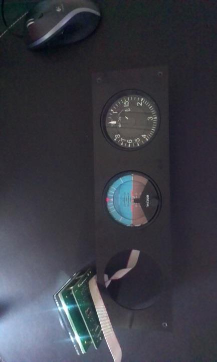
11 GSA-80 F16 IAS and Mach meter The third test was of the GSA-80 gauge which is a fairly new gauge within Flight Illusions product range. The GSA-80 is a replica of the airspeed and Mach meter found in the famous Lockheed Martin F-16 Fighting Falcon. The reason for why I selected this IAS gauge and not a standard B737 gauge with a barber pole was, because I wanted a gauge that was able to also indicate the Mach speed and not just knots. The GSA-80 features two stepper motors, one for driving the IAS needle from knots and the other for driving the secondary small faceplate within the gauge that shows the Mach number corresponding to the IAS at a given altitude / air pressure. The motion of the knots needle and the Mach faceplate is also super smooth and I noticed that even though I accelerate to speeds beyond 800 knots, the Mach meters faceplate still continues to turn and hereby it still provides the pilot with a reading. I also did the first test of this gauge without it being mounted and the sound level for this gauge resembles the altimeters 100% meaning that the sound was extremely low and when mounted into a frame and into my test rig, the sound was completely gone. Calibrating this gauge was however a bit tricky. You can twist the settings by using the software where you can put in values that equal to your IAS and then value pointers on the 360 degree rotation of the needle and faceplate but to do this I needed to measure the degree number for each IAS indication and do the calculation of degrees to software values. Below is an image of the Gauge Assignment and Setting together with the calibration table for the gauge.

12 First I needed to select which indicator I wanted to calibrate as e.g. I wanted to calibrate the IAS needle and not the Mach meter, so I selected the corresponding needle and clicked the button Calibrate which opens up the calibration window.

13 In the calibration window you see the Gauge Calibration area consisting of a Value input area to the left and the needle position area to the right. Furthermore it is stated that value 0 equals 0 degrees and value 1079 equals 360 degrees. By doing a little bit of math I calculated that one degree equals to value which in my conversion would be 3. Next part I had to do was to measure the degrees for each IAS indication number, and times that number with 3 would equal the value for the needle position input in the right column. When looking at the gauge it is easy to see that the IAS indication numbers are not with the same degree proportion from e.g. 100 to 200 knots then e.g. from knots, so therefore it was very important to measure the correct degree angle for each IAS indication number to get the needle to reach correctly. (The below numbers are not the 100% correct numbers, but instead one of my first tries before I did the calculation)


14 The specifics for the gauge are height and width of 83 mm, depth is 27 mm and the weight is app. 230 gr. Power requirements are 5/12 volts as described earlier and the gauge features two LEDs for the backlight function. Connection is a daisy chain 10 pin on a flat cable. As the previous two gauges I was also very impressed with this gauge. It really does resemble the real F-16 gauge down to even the smallest details and it is very clear to me that Flight Illusion does not make compromises in the realism and quality of their gauges. The gauge is quite complex and very advance and truly adds a lot to the flightsim experience for sure.


15 GSA-55PS Central Interface Board The GSA-55PS is the central interface board which is a PCB that connects the gauges or even modules to the computer. The CIB consists of a PCB with four connectors for the gauge/module strings, a USB connection for the connection between the PCB and the computer and a power supply connection that connects directly into a power convert which is connected directly into the wall socket using 220 volts. There is not that much to be said about the CIB other then it is a powerful PCB that can control a huge number of gauge/modules and that it is based on a daisy chain solution so that the wiring spaghetti is down to a minimal. Connection is easy and the PCB is ready to use as any plug and play module. The dimensions for the PCB are app. 82 mm x 82 mm and with a total height of 15 mm.

16 Conclusion My conclusion for this set of gauges including the PCB is that these units certainly are some very professional units of a high level of quality. The design and realism is absolutely superb and the gauges feel very authentic and create a super realistic atmosphere in the home cockpit. After trying out these three gauges I cannot understand why I didn t purchase a VSI and some navigational instruments as well that will for sure be something that I would invest in on a later point of time. Connecting and setting up the gauges and the PCB was super easy it was almost just plug and play when the software was installed, except for the GSA-80 gauge which had to be calibrated manually. When all gauges was setup the software could save that setup so that it only had to be done once which is excellent. Using the gauges in FSX does not require a lot of additional starting up time. Just start up the Flight Illusion software which takes about 3 seconds before you start up FSX. The software will align with FSX automatically and I found no loss in frame rates when applying these gauges to my setup. The software looked quite difficult to use at the beginning, but after taking a closer look to it I discovered that it was actually quite simple and easy to use it is built with a high level of logic and if you are in doubt there is of course also a downloadable manual from Flight Illusions website together with an FAQ and Forum section on their website as well. Building the frame(s) for the gauges is also very easy since Flight Illusion has created a download section on their website with actual 1:1 scale drawings of the cut-outs. I rated these gauges individually but the rating was actually the same for each gauge which is a perfect 5/5-Star rating. The gauges are absolutely a great addition to the home cockpit and I would certainly recommend these gauge to my fellow simmers. I know the price tag is quite high, but in my opinion they are defiantly worth every cent. Rays Aviation GSA-16 GSA-37 GSA-80 GSA-55PS
17
18
Test of GF MCP-PRO. Developed by GoFlight
 Test of GF MCP-PRO Developed by GoFlight Flightsim enthusiasts will continuously try to improve their virtual experience by adding more and more realism to it. To gain that effect today, you need to think
Review of. Siletz Bay Airport S-45. Produced by ORBX Systems
 Review of Siletz Bay Airport S-45 Produced by ORBX Systems Siletz Bay Airport is a small but public airport located a few miles southeast of Gleneden Beach in Lincoln County, Oregon, USA. The airport is
Test of. Harvey Airfield S43. Produced by ORBX Systems
 Test of Harvey Airfield S43 Produced by ORBX Systems Harvey Airfield a.k.a. Harvey Field is a small - medium size airport located in Snohomish, Washington, USA. The airfield was established back in 1944
Intro. Review of. Quest Kodiak. Created by Lionheart Creations
 Review of Quest Kodiak Created by Lionheart Creations Intro The Quest Kodiak is a single engine, turboprop, high winged, unpressurized aircraft featuring a fixed tricycle gear and built by Quest Aircraft
Review of. West YellowStone KWYS. Produced by ORBX Systems
 Review of West YellowStone KWYS Produced by ORBX Systems West Yellowstone Airport is a medium size, state owned, public used airport located one nautical mile north of the central business district of
Review of. MegaSceneryEarth Illinois Complete State. Created by PCAviator
 Review of MegaSceneryEarth 2.0 - Illinois Complete State Created by PCAviator The MegaSceneryEarth - Illinois is an add-on scenery landclass that improves the visuals when flying over the state of Illinois,
Review of. Felts Field Spokane KSFF. Created by ORBX Systems
 Review of Felts Field Spokane KSFF Created by ORBX Systems Felts Field is a medium size public airport located 4 nm northeast of Spokane, Washington. The aviation activities were started back in 1913 but
Review of. Longview Ranch Airport OG39. Created by ORBX Systems
 Review of Longview Ranch Airport OG39 Created by ORBX Systems Longview Ranch Airport is a small private airport located a few miles south of Kimberly in Wheeler County, Oregon, USA. The airport has no
Review of. Socata TBM850 HD Series. Created by Carenado
 Review of Socata TBM850 HD Series Created by Carenado The TBM850 is a single engine, low wing, turboprop, light business and utility aircraft manufactured by Socata since 2006. The TMB850 version is the
Height Limited Switch
 Height Limited Switch Manual version: 1.0 Content Introduction...3 How it works...3 Key features...3 Hardware...4 Motor cut-off settings...4 Specification...4 Using the RC HLS #1 module...5 Powering the
Review of. North American Aviation F-100D Super Sabre. Created by Milviz
 Review of North American Aviation F-100D Super Sabre Created by Milviz Intro The F-100D Super Sabre is a supersonic, single seat, single engine, low wing, military jet fighterbomber aircraft built by North
Ray Aviation Article. Lockheed F-35 Simulator. Simulator built by YouFly
 Ray Aviation Article Lockheed F-35 Simulator Simulator built by YouFly Intro My name is Raymond Andersen and some of you might know me better as Rays Aviation. I have had the pleasure of visiting the Danish
FlyRealHUDs Very Brief Helo User s Manual
 FlyRealHUDs Very Brief Helo User s Manual 1 1.0 Welcome! Congratulations. You are about to become one of the elite pilots who have mastered the fine art of flying the most advanced piece of avionics in
COMMERCIAL LEVEL SIMULATIONS
 PANEL AND VIRTUAL COCKPIT MANUAL COMMERCIAL LEVEL SIMULATIONS Commercial Level Simulations www.commerciallevel.com PANEL AND VIRTUAL COCKPIT MANUAL 1 Disclaimer This manual is not provided from, or endorsed
Review of. Piper PA44 Seminole. Created by Alabeo
 Review of Piper PA44 Seminole Created by Alabeo Intro The PA44 Seminole is a four seated, low wing, non-pressurized, twin piston engine, light personal, utility and training aircraft manufactured by the
USER MANUAL VOLANS PUBLIC DISPLAY FOR JOHN WAYNE AIRPORT
 VOLANS PUBLIC DISPLAY FOR JOHN WAYNE AIRPORT BridgeNet International Contents 1 Welcome... 2 1.1 Accessibility... 2 1.2 Navigation... 2 1.3 Interface Discovery... 4 2 Menu Bar... 5 2.1 Show Flights...
DXXX Series Servo Programming...9 Introduction...9 Connections HSB-9XXX Series Servo Programming...19 Introduction...19 Connections...
 DPC-11 Operation Manual Table of Contents Section 1 Introduction...2 Section 2 Installation...4 Software Installation...4 Driver Installastion...7 Section 3 Operation...9 D Series Servo Programming...9
Review of. KTVL Lake Tahoe Airport. Created by ORBX Systems
 Review of KTVL Lake Tahoe Airport Created by ORBX Systems Intro Lake Tahoe Airport is a medium size public airport located near the famous Lake Tahoe in El Dorado County, California and features a 8,541ft
Quality Gauges & Modules. for Simulation
 Quality Gauges & Modules for Simulation Flight Illusion is a young and dynamic company based in the Benelux, offering complete simulation solutions. Having a thorough knowledge of electronicmechanical-
RC Altimeter #2 BASIC Altitude data recording and monitoring system 3/8/2009 Page 2 of 11
 Introduction... 3 How it works... 3 Key features... 3 System requirements... 3 Hardware... 4 Specifications... 4 Using the RC Altimeter #2 BASIC module... 5 Powering the module... 5 Mounting the module...
Review of. McDonnell Douglas AV-8B Harrier II PLUS incl GR7 & GR9. Created by Razbam
 Review of McDonnell Douglas AV-8B Harrier II PLUS incl GR7 & GR9 Created by Razbam The Harrier II PLUS is a single seated, high winged, single engine, VSTOL, ground attack military aircraft built by McDonnell
VEX IQ Troubleshooting Flowchart Controller & Controller Battery
 Controller & Controller Battery Controller Power/Link Charge/Game Does the Controller turn on When on, the Power/Link LED will be green or red. Unscrew the battery door of the Controller and ensure both
STRUCTURE SENSOR QUICK START GUIDE
 STRUCTURE SENSOR 1 TABLE OF CONTENTS WELCOME TO YOUR NEW STRUCTURE SENSOR 2 WHAT S INCLUDED IN THE BOX 2 CHARGING YOUR STRUCTURE SENSOR 3 CONNECTING YOUR STRUCTURE SENSOR TO YOUR IPAD 4 Attaching Structure
Studuino Icon Programming Environment Guide
 Studuino Icon Programming Environment Guide Ver 0.9.6 4/17/2014 This manual introduces the Studuino Software environment. As the Studuino programming environment develops, these instructions may be edited
AlphaSim - Lockheed Martin F-22A Raptor
 AVSIM Commercial Aircraft Review AlphaSim - Lockheed Martin F-22A Raptor Publisher: AlphaSim Product Information Description: Lockheed Martin F-22A aircraft add-on Download Size: 30 MB Format: Manual Installation
Tel & Fax : Install and Operate Sharp Shape USB3D Foot Scanner Copyright, Sharp Shape, July 2014
 12891 Lantana Ave. Saratoga, CA 95070 Sharp Shape not just any shape www.sharpshape.com Tel & Fax : 408-871-1798 Install and Operate Sharp Shape USB3D Foot Scanner Copyright, Sharp Shape, July 2014 The
SkyView. Autopilot In-Flight Tuning Guide. This product is not approved for installation in type certificated aircraft
 SkyView Autopilot In-Flight Tuning Guide This product is not approved for installation in type certificated aircraft Document 102064-000, Revision B For use with firmware version 10.0 March, 2014 Copyright
USER MANUAL VOLANS PUBLIC DISPLAY FOR JOHN WAYNE AIRPORT
 VOLANS PUBLIC DISPLAY FOR JOHN WAYNE AIRPORT BridgeNet International Contents 1 Welcome... 2 1.1 Accessibility... 2 1.2 Navigation... 2 1.3 Map Display... 4 2 Menu Bar... 5 2.1 Show Flights... 5 2.2 Adjust
CNC Using the FlexiCam CNC and HMI Software. Guldbergsgade 29N, P0 E: T:
 CNC Using the FlexiCam CNC and HMI Software Guldbergsgade 29N, P0 E: makerlab@kea.dk T: +46 46 03 90 This grey box is the NC controller. Let s start by turning the red switch to the ON position, then press
Lock Cracker S. Lust, E. Skjel, R. LeBlanc, C. Kim
 Lock Cracker S. Lust, E. Skjel, R. LeBlanc, C. Kim Abstract - This project utilized Eleven Engineering s XInC2 development board to control several peripheral devices to open a standard 40 digit combination
Lockheed Constellation L-749
 AVSIM Commercial Aircraft Review Lockheed Constellation L-749 Publisher: Abacus Publishing Rating Guide Description: Add-on for Flight Simulator 2004 file:///c /AVSIM/Reviews/Connie/Connie.htm (1 of 9)15/05/2006
Flight Detector Indicator
 Flight Detector Indicator Part No: 777-1224-003 Components Maintenance Manual No: 34-25-12 By Soumyadeep Das Raj shekhar Chatterjee Purpose of equipment: The flight detector indicator (FDI) is a part of
Operating Handbook. For. Gemini Autopilot
 Operating Handbook For Gemini Autopilot TRUTRAK FLIGHT SYSTEMS 1488 S. Old Missouri Road Springdale, AR 72764 Ph. 479-751-0250 Fax 479-751-3397 www.trutrakap.com Table of Contents 1. Revisions... 5 2.
1090i. uavionix Ping1090i Transceiver QUICK START GUIDE
 1090i uavionix Ping1090i Transceiver QUICK START GUIDE Install 1 Install the uavionix Ping App from the Apple App Store or Google Play. Search for uavionix Ping Installer or use the QR codes below. Connect
Page intentionally left blank
 Page intentionally left blank SECTIONS STANDARD OBLÒ INSTALLATION OBLÒ-A/P INSTALLATION OBLÒ-REP INSTALLATION INSTRUMENT CONFIGURATION USING THE OBLÒ AUTOPILOT SYSTEM AUTOPILOT OPERATION USE OF THE OBLÒ-REP
Momo Software Context Aware User Interface Application USER MANUAL. Burak Kerim AKKUŞ Ender BULUT Hüseyin Can DOĞAN
 Momo Software Context Aware User Interface Application USER MANUAL Burak Kerim AKKUŞ Ender BULUT Hüseyin Can DOĞAN 1. How to Install All the sources and the applications of our project is developed using
Pro Flight Trainer Accuracy Flight Test Test-Pilot s guide Revision 2
 Pro Flight Trainer Accuracy Flight Test Test-Pilot s guide Revision 2 1 Pro Flight Trainer Accuracy Flight Test Pilot s guide Last revised 04.04.2017 1. Contents 1. flight dynamics (max 35)... 5 1.1. Induced
Midi Fighter 3D. User Guide DJTECHTOOLS.COM. Ver 1.03
 Midi Fighter 3D User Guide DJTECHTOOLS.COM Ver 1.03 Introduction This user guide is split in two parts, first covering the Midi Fighter 3D hardware, then the second covering the Midi Fighter Utility and
Exercise 6. Range and Angle Tracking Performance (Radar-Dependent Errors) EXERCISE OBJECTIVE
 EXERCISE OBJECTIVE") Exercise 6 Range and Angle Tracking Performance EXERCISE OBJECTIVE When you have completed this exercise, you will be familiar with the radardependent sources of error which limit range and angle tracking
Exercise 6 Range and Angle Tracking Performance EXERCISE OBJECTIVE When you have completed this exercise, you will be familiar with the radardependent sources of error which limit range and angle tracking
PARS Rocket Team. Avionics System Design Review. Ümit YELKEN
 PARS Rocket Team Avionics System Design Review Ümit YELKEN First aim of our avionics system is to control deployment of parachutes and transmit data to the ground station. The avionic system consists of
Virtual Flight Academy - Quick Start Guide
 Virtual Flight Academy - Quick Start Guide Ready to get started learning to fly or maintaining proficiency? EAA Virtual Flight Academy will help you build the confidence and competence to get it done!
Blue Point Engineering
 Blue Point Engineering Instruction I www.bpesolutions.com Pointing the Way to Solutions! Puppet - II+ Controller (BPE No. PCA-0001) Servo Position Adjustment EEPROM Digital Button Power 5 Vdc Playback
Wiring Techniques for Wiring a Lamp
 Supplies and Tools that you will need: Provided in your kit: Polarized lamp plug, 9 of SPT-1 18 AWG parallel lamp cord, bushings and grommets Items that you will need to provide: Phillips screwdriver,
TMC603EVAL MANUAL Evaluation board for the TMC603 three phase motor driver with BLDC back EMF commutation hallfx
 TMC603EVAL MANUAL Evaluation board for the TMC603 three phase motor driver with BLDC back EMF commutation hallfx TRINAMIC Motion Control GmbH & Co. KG Sternstraße 67 D 20357 Hamburg GERMANY www.trinamic.com
Rocketry Challenge - Technical Document I
 Rocketry Challenge - Technical Document I This document includes a list of what is inside the kit with pictures for hard to decipher parts and a simple step-by-step process of how to assemble and launch
Diamond Engraving Tool
 Diamond Engraving Tool Installation and Usage Guide (Covers kit & assembled versions of Diamond Engraving Tool) The Diamond Engraving Tool is an optional accessory for The Original Egg-Bot Kit, http://egg-bot.com/
Mach3 USB Motion Card (STB5100) Installation Manual
 Installation Manual") Mach3 USB Motion Card (STB5100) Installation Manual V2.1 The motion control card for machine control, with strong professional. Requires the operator to have the relevant expertise! If used improperly,
Mach3 USB Motion Card (STB5100) Installation Manual V2.1 The motion control card for machine control, with strong professional. Requires the operator to have the relevant expertise! If used improperly,
LV8716QAGEVK Evaluation Kit User Guide
 LV8716QAGEVK Evaluation Kit User Guide NOTICE TO CUSTOMERS The LV8716QA Evaluation Kit is intended to be used for ENGINEERING DEVELOPMENT, DEMONSTRATION OR EVALUATION PURPOSES ONLY and is not considered
SmartFly Cirrus Cirrus. Flight Trainer
 SmartFly SmartFly Cirrus Cirrus Flight Trainer The new PX-Eco Professional BATD Flight Simulator was engineered from the bottom up with a robust mechanism and our new SIMSOFT USB Digital Hardware Controller.
OPENCOCKPITS IOCard USBSTEPPER INSTALLATION AND USER S MANUAL
 OPENCOCKPITS IOCard USBSTEPPER INSTALLATION AND USER S MANUAL INTRODUCCION This card allows to manage up to 3 stepper motors, both unipolar as bipolar. Also, this card can easily control the steppers motors
Introduction. Overview. Outputs Normal model 4 Delta wing (Elevon) & Flying wing & V-tail 4. Rx states
 & Flying wing & V-tail 4. Rx states") Introduction Thank you for purchasing FrSky S6R/S8R (SxR instead in this manual) multi-function telemetry receiver. Equipped with build-in 3-axis gyroscope and accelerometer, SxR supports various functions.
Introduction Thank you for purchasing FrSky S6R/S8R (SxR instead in this manual) multi-function telemetry receiver. Equipped with build-in 3-axis gyroscope and accelerometer, SxR supports various functions.
S.I.C. Connections, Wiring Diagrams & Schematics
 S.I.C. Connections, Wiring Diagrams & Schematics TRC Development 005 Nothing from this document may be reproduced in writing or electronically without written permission of TRC Development b.v. The names
INSTRUCTIONS. 3DR Plane CONTENTS. Thank you for purchasing a 3DR Plane!
 DR Plane INSTRUCTIONS Thank you for purchasing a DR Plane! CONTENTS 1 1 Fuselage Right wing Left wing Horizontal stabilizer Vertical stabilizer Carbon fiber bar 1 1 1 7 8 10 11 1 Audio/video (AV) cable
Application Note. Communication between arduino and IMU Software capturing the data
 Application Note Communication between arduino and IMU Software capturing the data ECE 480 Team 8 Chenli Yuan Presentation Prep Date: April 8, 2013 Executive Summary In summary, this application note is
LESSONS Lesson 1. Microcontrollers and SBCs. The Big Idea: Lesson 1: Microcontrollers and SBCs. Background: What, precisely, is computer science?
 LESSONS Lesson Lesson : Microcontrollers and SBCs Microcontrollers and SBCs The Big Idea: This book is about computer science. It is not about the Arduino, the C programming language, electronic components,
Experiment P10: Acceleration of a Dynamics Cart II (Motion Sensor)
") PASCO scientific Physics Lab Manual: P10-1 Experiment P10: (Motion Sensor) Concept Time SW Interface Macintosh file Windows file Newton s Laws 30 m 500 or 700 P10 Cart Acceleration II P10_CAR2.SWS EQUIPMENT
PASCO scientific Physics Lab Manual: P10-1 Experiment P10: (Motion Sensor) Concept Time SW Interface Macintosh file Windows file Newton s Laws 30 m 500 or 700 P10 Cart Acceleration II P10_CAR2.SWS EQUIPMENT
PSoC Academy: How to Create a PSoC BLE Android App Lesson 9: BLE Robot Schematic 1
 1 All right, now we re ready to walk through the schematic. I ll show you the quadrature encoders that drive the H-Bridge, the PWMs, et cetera all the parts on the schematic. Then I ll show you the configuration
SP-6 magnetometer. User manual. Installation and in-flight calibration
 SP-6 magnetometer User manual Installation and in-flight calibration Note: This manual is applicable for SP-6 systems that contain in-flight calibration firmware released by MGL Avionics around the 15
Guitar Tuner. EET 2278 Capstone Project. Tyler Davis. Sinclair Community College. EET 2278 Spring Professor Russo
 Guitar Tuner EET 2278 Capstone Project Tyler Davis Sinclair Community College EET 2278 Spring 2016 Professor Russo 2 Table of Contents ACKNOWLEDGEMENTS... 3 ABSTRACT... 4 INTRODUCTION... 5 PRINCIPLES OF
Experiment P55: Light Intensity vs. Position (Light Sensor, Motion Sensor)
") PASCO scientific Vol. 2 Physics Lab Manual: P55-1 Experiment P55: (Light Sensor, Motion Sensor) Concept Time SW Interface Macintosh file Windows file illuminance 30 m 500/700 P55 Light vs. Position P55_LTVM.SWS
PASCO scientific Vol. 2 Physics Lab Manual: P55-1 Experiment P55: (Light Sensor, Motion Sensor) Concept Time SW Interface Macintosh file Windows file illuminance 30 m 500/700 P55 Light vs. Position P55_LTVM.SWS
FRUIT BONUS 2 nd Generation 2004 AMCOE INC.
 PIN PARTS SIDE SOLDER SIDE PIN 1 VIDEO RED VIDEO GREEN 1 2 VIDEO BLUE VIDEO SYNC 2 3 SPEAKER + SPEAKER - 3 4 EXTRA - 4 5 EXTRA - STOP 2 EXTRA - ALL STOP 5 6 EXTRA - STOP 3 6 7 TICKET OUT BUTTON - panel
Legacy Woodworking Machinery a division of Phantom Engineering. The Legacy CNC. Assembly Manual
 Legacy Woodworking Machinery a division of Phantom Engineering The Legacy CNC Assembly Manual New Orientation of the Legacy Step one: Re-orientation of the machine Remove the X-axis screw and supports.
Radio Link Starter Kit
 Radio Link Starter Kit Installation Manual BARTLETT Instrument Co. 1032 Avenue H Fort Madison, IA 52627 319-372-8366 www.bartinst.com Table of Contents Radio Link Starter Kit Manual... 3 System Requirements...
We would love to hear from you and post your wonderful creations on our Facebook page to share with others.
 Pro Bow The Hand www.probowthehand.com Instructions for Large Hand 1 Ribbon Congratulations on your purchase of Pro Bow The Hand. This item truly revolutionizes the construction of bows. Never before has
Post-Installation Checkout All GRT EFIS Models
 GRT Autopilot Post-Installation Checkout All GRT EFIS Models April 2011 Grand Rapids Technologies, Inc. 3133 Madison Avenue SE Wyoming MI 49548 616-245-7700 www.grtavionics.com Intentionally Left Blank
Using the USB2.0 camera and guider interface
 Using the USB2.0 camera and guider interface The USB2.0 interface is an updated replacement for the original Starlight Xpress USB1.1 unit, released in 2001. Its main function is to provide a USB2 compatible
STRUCTURE SENSOR & DEMO APPS TUTORIAL
 STRUCTURE SENSOR & DEMO APPS TUTORIAL 1 WELCOME TO YOUR NEW STRUCTURE SENSOR Congrats on your new Structure Sensor! We re sure you re eager to start exploring your Structure Sensor s capabilities. And
Name EET 1131 Lab #2 Oscilloscope and Multisim
 Name EET 1131 Lab #2 Oscilloscope and Multisim Section 1. Oscilloscope Introduction Equipment and Components Safety glasses Logic probe ETS-7000 Digital-Analog Training System Fluke 45 Digital Multimeter
uavionix Ping2020 Transceiver
 uavionix Ping2020 Transceiver QUICK START GUIDE Install 1 Install the uavionix Ping App from the Apple App Store or Google Play. Search for uavionix Ping Installer or use the QR codes below. Connect the
Ninja 250. Storm Racing Drone With CC3D Controller USER MANUAL V3. HeliPal.com. All Rights Reserved
 Ninja 250 Storm Racing Drone With CC3D Controller USER MANUAL V3 1 DISCLAIMER Please read this disclaimer carefully before using this product. This product is a hobby with motors but not a toy which is
DragonLink Advanced Transmitter
 DragonLink Advanced Transmitter A quick introduction - to a new a world of possibilities October 29, 2015 Written by Dennis Frie Contents 1 Disclaimer and notes for early release 3 2 Introduction 4 3 The
Assembly Instructions: Kit #5
 Assembly Instructions: Kit #5 1. Insert the T-pin into one of the caps. 2. Insert the rotor core into the same cap as shown below. Apply some pressure to push the rotor core approximately 1/2" (10-12 mm)
Lab 5: Inverted Pendulum PID Control
 Lab 5: Inverted Pendulum PID Control In this lab we will be learning about PID (Proportional Integral Derivative) control and using it to keep an inverted pendulum system upright. We chose an inverted
User Manual Version 1.0
 1 Thank you for purchasing our products. The A3 Pro SE controller is the updated version of A3 Pro. After a fully improvement and optimization of hardware and software, we make it lighter, smaller and
Ultimate Actuator Drivebox 30A Quick start guide
 2016 Ultimate Actuator Drivebox 30A Quick start guide info@e-tronix.cz e-tronix s.r.o. 1.1.2016 OBSAH Identification... 3 Serial Number... 3 Manufacturer and reseller contact... 4 Before Start... 4 UAD30A
Assembly Guide for Printrbot - Simple Maker s Edition 1405
 Assembly Guide for Printrbot - Simple Maker s Edition 1405 Last update: March 2016 Please Note: be careful on the steps that are underlined 1 Contents Tools Needed:... 3 First step: Check components and
AgilEye Manual Version 2.0 February 28, 2007
 AgilEye Manual Version 2.0 February 28, 2007 1717 Louisiana NE Suite 202 Albuquerque, NM 87110 (505) 268-4742 support@agiloptics.com 2 (505) 268-4742 v. 2.0 February 07, 2007 3 Introduction AgilEye Wavefront
MGL Avionics Garrecht VT-0102 mode-s transponder Interface installation manual
 MGL Avionics Garrecht VT-0102 mode-s transponder Interface installation manual Document date: September 2012 This document should be read in conjunction with the Garrecht VT-0102 installation manual General
Programming 2 Servos. Learn to connect and write code to control two servos.
 Programming 2 Servos Learn to connect and write code to control two servos. Many students who visit the lab and learn how to use a Servo want to use 2 Servos in their project rather than just 1. This lesson
Troubleshooting Rig Connection Issues
 Rig Control Page 1 Troubleshooting Rig Connection Issues There are many reasons HRD can not or will not connect to your radio during initial setup of the software. This document will walk you through some
Performance. CNC Turning & Milling Machine. Conversational CAM 3.11 Instruction Manual
 Performance CNC Turning & Milling Machine Conversational CAM 3.11 Instruction Manual Legacy Woodworking Machinery 435 W. 1000 N. Springville, UT 84663 Performance Axis CNC Machine 2 Content Warranty and
AlphaSim - F4D Skyray
 AVSIM Commercial Aircraft Review AlphaSim - F4D Skyray Publisher: AlphaSim Product Information Description: Aircraft Add-on Download Size: 10.2 MB Format: Download Simulation Type: FS 2004 Reviewed by:
Google Earth Tutorials
 Google Earth Tutorials Tutorial 1 Beginner Videos 1: Street View Now you can fly from outer space down to the streets with Street View. Seamlessly integrated with Google Earth, Street View lets you experience
ezsystem elab16m Light Sensing Robot
 ezsystem elab16m Light Sensing Robot ezsystem The aim of ezsystem is to enable Creativity and Innovation at an early age in a Problem Based Learning (PBL) approach. ezsystem integrates ezcircuit Designer,
Veterinary Digital X-Ray System Quick Start Guide
 1 Veterinary Digital X-Ray System Quick Start Guide 2 SOPIX² X-Ray Sensors Quick Start Guide ***PERFORM THIS STEP BEFORE PLUGGING IN THE SENSOR*** Step 1 Load the CD: If you have already plugged in the
Aerospace Education 8 Study Guide
 Aerospace Education 8 Study Guide History of Rockets: 1. Everything associated with propelling the rocket 2. Whose laws of motion laid the scientific foundation for modern rocketry? 3. Who was the first
INCLINED PLANE RIG LABORATORY USER GUIDE VERSION 1.3
 INCLINED PLANE RIG LABORATORY USER GUIDE VERSION 1.3 Labshare 2011 Table of Contents 1 Introduction... 3 1.1 Remote Laboratories... 3 1.2 Inclined Plane - The Rig Apparatus... 3 1.2.1 Block Masses & Inclining
Diamond Engraving Tool
 Diamond Engraving Tool Installation and Usage Guide (For both kit and assembled versions of Diamond Engraving Tool) The Diamond Engraving Tool is an optional accessory for The Original Egg-Bot Kit, http://egg-bot.com/
GRT Autopilot User Guide. All GRT EFIS Systems
 All GRT EFIS Systems Revision A 22-May-2014 Copyright 2014 3133 Madison Ave. SE Wyoming, MI 49548 (616) 245-7700 www.grtavionics.com Revision Notes Revision Date Change Description A 22-May-2014 Complete
INSTRUCTION MANUAL Version 1.0
 INSTRUCTION MANUAL Version 1.0 Camera Geotagger For Nikon or Canon GPS plus Beidou Barometric altimeter Position Tracing Logger Shutter Release Remoter LCD display Bluetooth technology GPS Contents Introduction
King Cloud III. Warning. Obstruction Detection. Instructions for Reclining Sofas
 Instructions for Reclining Sofas Warning Do not sit on footrest when in open reclined/extended position. MAXIMUM LOAD 15 KG. Always RETRACT FOOTREST prior to standing. Obstruction Detection IF THE RECLINER
INSTALLATION & OPERATION MANUAL
 INSTALLATION & OPERATION MANUAL PREFACE This installation & operation manual is intended as an instruction manual for trained person who is in charge of installation, maintenance, repair, etc. Before installation
Radio Link Starter Kit
 Radio Link Starter Kit Installation Manual BARTLETT Instrument Co. 1032 Avenue H Fort Madison, IA 52627 319-372-8366 www.bartinst.com Table of Contents Radio Link Starter Kit Manual... 3 System Requirements...
Myostat Motion Control Inc. Cool Muscle 1 RT3 Application Note. Program Bank Notes for Cool Muscle Language
 Myostat Motion Control Inc. Cool Muscle 1 RT3 Application Note Program Bank Notes for Cool Muscle Language 1. Program Banks 1. Basic Program Bank This example shows how to write a very basic program bank
A3 Pro INSTRUCTION MANUAL. Oct 25, 2017 Revision IMPORTANT NOTES
 A3 Pro INSTRUCTION MANUAL Oct 25, 2017 Revision IMPORTANT NOTES 1. Radio controlled (R/C) models are not toys! The propellers rotate at high speed and pose potential risk. They may cause severe injury
Exclusive Preview. for simflight.com. By Johan Peeters
 for simflight.com By Johan Peeters 2 Exclusive Preview About The Lockheed-Martin F-16 Fighting Falcon The F-16 Fighting Falcon is a compact, multirole fighter aircraft. It is highly maneuverable and has
Short Instruction Manual. pp-rc Modellbau Weidenstieg Kölln-Reisiek Deutschland
 Short Instruction Manual 22.03.2010 Distribution: pp-rc Modellbau Weidenstieg 2 25337 Kölln-Reisiek Deutschland Tel.: +49 (0) 4121 740486 Fax: +49 (0) 4121 750676 www-pp-rc.de WEEE-Reg.-Nr DE77074747 Dear
FABO ACADEMY X ELECTRONIC DESIGN
 ELECTRONIC DESIGN MAKE A DEVICE WITH INPUT & OUTPUT The Shanghaino can be programmed to use many input and output devices (a motor, a light sensor, etc) uploading an instruction code (a program) to it
LVTX-10 Series Ultrasonic Sensor Installation and Operation Guide
 LVTX-10 Series Ultrasonic Sensor Installation and Operation Guide M-5578/0516 M-5578/0516 Section TABLE OF CONTENTS 1 Introduction... 1 2 Quick Guide on Getting Started... 2 Mounting the LVTX-10 Series
Blue Point Engineering
 Blue Point Engineering Instruction I www.bpesolutions.com Pointing the Way to Solutions! Animatronic Wizard - 3 Board (BPE No. WAC-0030) Version 3.0 2009 Controller Page 1 The Wizard 3 Board will record