RADIO PHONE AND TELEGRAPH RECEIVERS
|
|
|
- Margery Perry
- 5 years ago
- Views:
Transcription


1 CONSTRUCTION OF RADIO PHONE AND TELEGRAPH RECEIVERS FOR BEGINNERS By M. B. SLEEPER THE NORMAN W. HENLEY PUBLISHING CO. 2 WEST 45th STREET, NEW YORK 1922 EDITION


2 Stonow;-11 School Library CONSTRUCTION OF RADIO PHONE AND TELEGRAPH RECEIVERS FOR BEGINNERS SOLID, USEFUL DATA, PHOTOS, AND DRAWINGS PREPARED SPECIALLY FOR THE RADIO NOVICE AND EXPERIMENTER ON THE ERECTION OF ANTENNAS, PLANNING A STATION, AND BUILDING ALL KINDS OF CRYSTAL, AUDION, AND REGENERATIVE RECEIVERS, WITH AMPLIFIERS AND LOUD SPEAKERS FOR RADIO TELEPHONE BROADCAST RECEPTION AND TELEGRAPH SIGNALS BY M. B. SLEEPER Author of "Design Data," "Radio Hook -Ups," etc. Standardization Committee, I. R. E., Editor "Radio and Model Engineering" NEW YORK THE NORMAN W. HENLEY PUBLISHING CO. 2 WEST 45TH STREET 1922


3 COPYRIGHTED, 1922 BY THE NORMAN W. HENLEY PUBLISHING CO. PRINTED IN U.S.A. Composition. Electrotyping and Press Work ßy Publishers Printing Company. New York


4 A 1922 EVENING'S ENTERTAINMENT Listening to One of the Radio Phone Broadcasting Stations

5


6 44 o PREFACE T A radio book which attempts to teach is often less helpful than one which simply tells. In Radio Phone and Telegraph Receivers, explanations which are liable to puzzle rather than assist the experimenter have been carefully avoided, for education in radio generally works backward from practice to theory instead of following the academic order. This volume, therefore, is a predecessor of Design Data, though it appears at a later date. From the understanding gained by following instructions in building apparatus the novice is better equipped to experiment and design instruments according to his own ideas. The interests of the novice who is desirous of receiving the radio broadcasting stations has been kept in mind, and equipment which can be installed in the parlor of one's home is described. It is hoped that this book will meet the needs of the novice and experimenter, -*and will be of benefit to both in the designing and building of receiving equipment. e April, 1922, tij New York City. w a o -re o longer Propertycalk. uu Yu k,lic Library M. B. SLEEPER.


7 i
8
 or or or Variable Capacitance (Var.")
 --- OL Fixed Coupling of Coils ( Fixed Inductive Coupling) \"-0(1000P- Variable")
9 -- LIST OF SYMBOLS - Battery Direct Current Dynamo --- Alternating Current Generator Fixed Capacitance ( Condenser ) or or or Variable Capacitance (Var. Condenser) Fixed Inductance (Air Core Coil) Variable Inductance ( Air Core Coil ) 6Ö0000 `- or 10-0 Var/ome te r ( Variable Induc/ance) --- OL Fixed Coupling of Coils ( Fixed Inductive Coupling) "-0(1000P- Variable Coupling of Cods Transformer Iron Core Inductance ( or Reactance Coi/)


10 LIST OF SYMBOLS Antenna Ground t) Wire Connections No Connections of Wires i or Fixed Res/stance Variable Resistance Vacuum Tube or - Telephone Receivers Voltmeter Ammeter VOLTS z AMPERES Galvanometer GALVO. Crys/a/ Detector
11 1 ). J

12 TABLE OF CONTENTS CHAPTER I ERECTION OF SENDING AND RECEIVING ANTENNAS This chapter tells how transmitting antennas suitable for 200 meter transmission can be constructed and also receiving antenna for the reception of radio phone broadcasting stations and long wave European Stations Page 15 CHAPTER II BUILDING A TWO -SLIDE TUNING COIL A description of just how to make the simplest type of Radio Receiving Tuner is given Page 22 CHAPTER III INSTALLING AND CONNECTING UP A SIMPLE RECEIVER This chapter tells how to use the tuning coil in connection with a crystal detector, the antenna and other necessary parts... Page 27 CHAPTER IV z A RECEIVER FOR NAVY CODE PRACTICE A description of a simple receiver for the reception of the Naval Spark Stations is given so that the beginner may obtain practice in the telegraph code. This receiver will also be very satisfactory for the reception of the phone broadcasting stations.... Page 31 CHAPTER V RECEIVING INSTRUMENTS ON STANDARDIZED PANELS This chapter deals with the arrangement of a simple receiver, built on panels which makes it possible to improve the appearance of the set, and at the same time maintain all of the flexibility of an experimental outfit Page 34 7


13 8 Table of Contents CHAPTER VI SOME IDEAS FOR A CRYSTAL RECEIVER Details of a panel type crystal set are given with some useful refinements. Page 42 CHAPTER VII AUDION CONTROL PANELS A panel type audion detector and control unit is described in detail. Page 51 CHAPTER VIII CONSTRUCTION OF A PORTABLE RECEIVER A portable audion receiver for use on Camping Trips, which weighs only 12% pounds complete, including antenna material, is described in detail Page 57 CHAPTER IX CRYSTAL RECEIVER FOR 200 TO 600 METERS A unique crystal receiver with some interesting constructional details is illustrated and described Page 68 CHAPTER X THE USE OF CONCENTRATED INDUCTANCE COILS Some interesting notes on Honeycomb and Duo Lateral Coils is given as well as curves and formulas for the calculation of the proper coils to use for any wavelength range under a given set of conditions. Page 76 CHAPTER XI A SIMPLE REGENERATIVE RECEIVER A regenerative receiver, which is cheaper to build and easier to operate than the usual type is described quite fully. The regenerative receiver, though more difficult to operate than the ordinary type, is far more sensitive Page 88 CHAPTER XII VARIOMETER TYPE REGENERATIVE RECEIVER This is the usual type of regenerative receiver. Some interesting tests of a variometer and constructional details of a very satisfactory receiver are given Page 94


14 Table of Contents 9 CHAPTER XIII TWO-STEP AUDIO FREQUENCY AMPLIFIER In order to increase the strength of received signals, an amplifier is required. The two-step unit described in the chapter, which is made from standard parts, is very efficient and easy to construct. Page 105 CHAPTER XIV BUILDING A RADIO FREQUENCY AMPLIFYING TRANSFORMER When signals have been amplified by an audio frequency amplifier of two stages and are still weak, the radio frequency amplifier must be used. Details of the radio frequency transformer are furnished in this chapter Page 115 CHAPTER XV RADIO AND AUDIO FREQUENCY AMPLIFIER A very useful receiver for use on very weak signals or loop antennas is fully described. It consists of a radio frequency amplifier, detector, and audio frequency amplifier Page 121 CHAPTER XVI RADIO FREQUENCY AMPLIFIERS WITHOUT TRANSFORMERS The impedance coupled radio frequency amplifier, which does not require the transformer described in Chapter XIV is described. This amplifier is very satisfactory and does not need much equipment. Page 129 CHAPTER XVII THE LOUD SPEAKING RECEIVER AND AMPLIFIER With music, etc., in the air the old telephone receivers are falling into disfavor, because of the limitation on the number of listeners. The loud speaking receiver solves this difficulty. This chapter describes a way of making such a receiver and its necessary associated amplifier Page 136 CHAPTER XVIII THE RADIO SET FOR THE PARLOR A set is described which makes use of a Phonograph Cabinet for mounting the radio equipment and the phonograph horn for the Loud Speaking Receiver Page 140

15 s


16 longer property 01 the -ton Public Library CONSTRUCTION OF RADIO PHONE AND TELEGRAPH RECEIVERS FOR BEGINNERS CHAPTER I ERECTION OF SENDING AND RECEIVING ANTENNAS In the construction of a radio station, naturally the first thing to consider is the antenna system for both the receiver and transmitter. There are a number of types which are adaptable for transmitting-only two of which-the Umbrella and the T or inverted L will be described. The umbrella is suitable for a house of the general type shown in Fig. 1, for the ridge pole and two gables offer convenient means for fastening the wires. The height of the pole should not exceed 25 feet or the length of wires 35 feet so that it will be suitable to operate on the required transmitting wavelength of 200 meters. The height of the roof and the material of the building will affect the capacity, so that definite dimensions cannot be given. In all events, this size is large enough, and, if too large, can be reduced, or a series condenser inserted in the ground lead of the transmitter. That latter method of reducing the wavelength is not advisable for a station which is to operate at maximum power. Several methods can be employed to bring off the lead-in. The wires may be insulated at the top and bottom and connected to- gether at the top for a lead at this point or from the foot of one of the wires. If an iron mast is employed, it can be held in 15

 are used, preferably porcelain insulators should be used.")
17 16 Radio Phone and Telegraph Receivers porcelain, glass or Electrose insulators, and a lead taken from the base. In this case, the wires must be connected to the mast at the upper end. Copper clad iron wire, phosphor bronze, or solid copper wire is suitable for. the conductors. No. 14 copper clad or phosphor bronze wire will serve for an umbrella or T antenna, or No. 12 solid copper. For transmitters up to 1 K. W., 10 -in Electrose strain insulators are needed; 5 -in. insulators are sufficient for spark coil sets. In up-to-date wireless installations, where continuous waves (those generated by a vacuum tube or audion set) are used, preferably porcelain insulators should be used. Variations of the L or T antenna are usually easier to install than the umbrella type. Fig. 2 shows an antenna of this sort. For 200 meters, the length plus the height should not exceed 100 feet. In the case of an apartment house, the height of the antenna is figured from the ground connection of the apparatus to the aerial wires. If the antenna slopes, the average height of the wires is taken. In many instances, the aerial can be run from the roof of the house to a short pole, 20 or 25 feet high. The wire and insulation for this type are the same as those already described. The lead can be taken from any part of the antenna without greatly affecting its efficiency. The important feature is the length of the lead-in, which must be as short as possible. Wires can be brought down as in Fig. 2, or a single wire can be connected to the antenna conductors and brought down into the station. It is not necessary to connect the wires at the ends of the aerial. Four wires spaced 2 to 4 feet apart are nearly as efficient as a larger number of wires. The 200 meter antenna will serve for transmitting or receiving experimental or commercial stations up to 3,000 meters. Long distance and long wave reception require a different antenna. For long distance reception the most effective and widely used type of antenna consists of a low long wire approximately 30 feet high and 200 to 500 feet long. The advantage gained by using


18 :237


19 18 Radio Phone and Telegraph Receivers higher antennas is compensated for by using slightly more amplification in the receiver. Signals have been copied from a station more than 7,000 miles away using a regenerative receiver, of the type to be described in a later chapter, on an antenna less than thirty feet high. In both Figs. 1 and 2 a single wire receiving antenna as well as the transmitting antenna is shown. Many people are becoming interested in radio because of the many radio broadcasting stations distributed all over our country which maintain regular and interesting musical entertainment and educational programs. A single wire antenna as high above surrounding buildings, etc., as it is possible to put it and approximately one hundred and fifty feet long is an ideal antenna to receive the 360 meter radio broadcasting stations. This antenna is similar to the single wire antenna of Fig. 2. Experimenters who want to copy French and German stations as well as the transmitters on shorter wavelengths will find it necessary to use a separate long wire, as indicated in the illustrations. A switch can be set up, inside the operating room, to change from one antenna to the other as desired. Aluminum wire should not be used for any type of antenna. It is not strong enough, and causes a loss in efficiency due to the oxidization of the joints. Besides the aerials described, there is the loop which must not be forgotten. In fact, it is coming into wide use. Aside from its application to the direction finder, it is adaptable to the regular work of receiving. The loop antenna uses no ground connection. Instead, one end of the loop is connected to the antenna post, and the other end to the ground post of any receiving set. It can be installed on the ground beside the wireless shack or inside a house or apartment building. In any case, it must be arranged so that the operator can turn it to point toward the transmitting station. A loop can be used for short distance transmission, though for this purpose it is not particularly efficient. On the other hand,


20 ti ß.,i1, l


21 20 Radio Phone and Telegraph Receivers it gives directive transmission, another step toward the elimination of interference. It must be remembered that, in a loop, the capacity is negligible and the inductance paramount, while the opposite is true of a grounded antenna. Therefore, for both sending and receiving, a condenser must be connected across the ends of the loop. The loop though possessing the advantages outlined is quite inefficient and therefore requires much more amplification than the Transmitting Receiving Antenna Antenna To Transmitter 500 Volt ido Ampere Single Pole Dou ble Throw Switch *4 Copper Wire Switch must be Locatedon Outside Wall of Building Lightning Arrester or Spark Gap e Telephone Type Fuse!Amp. To Receiver Lightning Arresterand Fuse maybe Located inside of Building Ground Ground Fig. 3.-Protection of antenna systems from lightning. open wire antenna. This involves vacuum tubes, batteries and much miscellaneous apparatus. For this reason the elevated open wire type of antenna is most widely used. In order to make this subject complete, a word or two about the protection of the transmitting and receiving antennas will be given. The fire underwriters require that each transmitting antenna shall be protected against lightning by a single pole double throw switch (500 volt, 100 ampere size), which connects the antenna to ground at all times when it is not in use. The ground wire must be a No. 4 stranded copper wire. The antenna leads must not come

22 Erection of Sending and Receiving Antennas 21 closer than five inches to the building and the antenna grounding switch and ground wire must be on the outside wall of the building. Receiving antennas are considered in a different light. They are considered of no greater hazard than telephone lines and should be protected in the same way. A lightning arrester of the telephone variety or a one -eighth inch spark gap should be connected between the antenna lead-in and ground and the receiving instruments protected by a one ampere telephone type fuse in the lead between the lightning arrester or spark gap and the receiving set. Fig. 3 illustrates the protection necessary for the two types of antennas.


23 CHAPTER II BUILDING A TWO -SLIDE TUNING COIL This chapter deals with the simplest type of receiving tuning device. The tuning coil described is of such constants that when used with the single 150 -foot wire described in Chapter 1, and a suitable detector the radio telephone signals from any one of the numerous broad -casting stations can be heard, if not more than say, F g. 4.-Fastening the start of the winding. fifty- or seventy-five miles away. Commercial and Naval Telegraph stations can also be heard up to distances of several hundred miles at night. A tuning coil consists essentially of a number of turns of small wire, with one, two or three sliders which cut in any desired number of turns along the length of the coil. 22 C


24 Building a Two -Slide Tuning Coil 23 The tube on which the coil is to be wound should receive the first consideration. Thin, spiral -wound mailing tubes are not satisfactory because they shrink after the wire has been wound on Fig. 5.-The winding rig them. If cardboard tubes are used they should be of the straight wound type 1/8 or 3/16 in. thick. The tube used for the coil illustrated here was 4 ins. in diameter and 7 ins. long. This is a convenient size, and enough wire can be wound upon it to give Fig. 6.-The wire straightener. a considerable range in wavelength. Bakelite or formica tubing is much better, as it keeps its shape indefinitely. Fibre tubing should not be used, as it absorbs a very large amount of moisture.


25 24 Radio Phone and Telegraph Receivers First, it is necessary to make a line around the end of the tube for the purpose of cutting it off accurately, as it is essential to have the ends square and true. The tube is held against a board at right angles to the end piece. As the tube is rotated, a pencil held against it will make a true line. The ends are finished by sandpapering and two holes drilled 1/2 in. from each end and the wire put through them, as shown in Fig. 4. No. 24 single silk covered wire is always easy to obtain, and in general the most satisfactory for a coil of this type. The winding rig consists simply of a 1/4 in. steel rod threaded its full length and fitted with nuts and washers, which clamp two wooden cones against the tubing, or it can be constructed as in Fig. 5. Fig. 7.-The method of operation. In use the wire is guided with one hand and the coil turned with the other. Clamping the rig to the bench or table makes the work easier. Because the small kinks in the wire show up so plainly on the coil, a straightener, Fig. 6, is needed. This is made up from three fibre spools mounted on a wooden block, with screw eyes to guide the wire. The end of the winding is fastened in the same way as the beginning, leaving leads long enough to extend to the tuning posts on the end pieces. Some experimenters prefer to use No. 24 bare copper wire, winding it on with a thread, Fig. 7, so that there


26 Building a Two -Slide Tuning Coil 25 is a separation between the turns. This makes a much better looking coil, and does not offer the difficulties in removing insulation for the sliders as when covered wire is used. In either ease, the completed coil should be varnished with a heavy coat of spar varnish, and if possible dried in a heat of about 125 F. The next operation in the construction of the coil is to make the end pieces. Hard rubber or bakelite look very well, but for prac- -- tical use any well finished wood will serve the purpose. If a tube 4 in. in diameter has been used, the end pieces should be about 1 in. larger on a side than the diameter of the coil and the thickness between 1/2 and 3/4 in. Two methods can be used for t=- c,, fi, ; ::, ',..,., 1_ Fig. 8.-Details of the tuning coil holding the end pieces together. One is the use of perfectly flat end pieces, clamping them to the ends of the tube by means of a threaded brass rod running through the center of the coil. The other is to cut a hole in each piece which will take the tube. Then this can be glued in place. The sliders are made of square brass tubing 1/4 or 3/16 in. square inside, moving on square brass rods. These slider rods are sometimes held to the upper sides of the end pieces by wood screws, or the ends of the rods can be turned down and threaded to fit in holes in the end pieces. This method offers
27 26 Radio Phone and Telegraph Receivers the advantage that binding posts can be fitted directly to the ends of the rods at the outside of the end pieces. The sliders can be made with a spring soldered to the tube, but this generally takes the spring out of the contact. It is better, therefore, to clamp the contact beneath the hard rubber handle. Fig. 8 shows a completed tuner of the type described.

28 CHAPTER III INSTALLING AND CONNECTING UP A SIMPLE RECEIVER With the broadcasting receiving antenna described in Chapter I, surprisingly long distances can be covered with a simple tuning coil of one, two or three slides. In fact the advantages from the use of a loose coupler are mainly in sharper tuning and not longer distance reception. For ordinary receiving work on a small antenna a coil 4 in. in diameter and 7 in. long similar to that described in Chapter II is large enough. Such a coil will copy the Arlington time signals and practically all commercial stations using spark transmitters. One slider will give good results, two slides a little sharper tuning, while three sliders give slightly closer tuning but are rather troublesome to adjust. In general, a two -slide tuner gives the most satisfactory results. Novices or experimenters who are taking up radio work for the first time should have their first experience with a crystal detector. The audion is rather expensive for learning, and requires considerable skill to operate efficiently. Galena has been the most popular mineral for a crystal detector. It was considered necessary, at first, to use an extremely fine adjustment, but, actually, a good crystal will give perfect satisfaction with a roughly adjusted catwhisker or fine copper wire. It may be stated that a copper wire, about No. 30 gauge, works as well as any other metal. If possible, a tested crystal should be purchased. Otherwise it is necessary to buy a large piece and break it into cubes about % of an in. square. Silicon is still used. It is not as sensitive as galena, yet it will keep its adjustment for a long time. A slightly blunt brass point, 27


29 28 Radio Phone and Telegraph Receivers arranged so that a rather heavy pressure can be applied, is commonly used. Sometimes two crystals in contact with each other are used. The two pairs most commonly used are zincite and chalco-pyrites or bornite and chalco-pyrites. Fig. 9. Diagram of connections of detector and phones. Diagram of connections of one slide tuning coil, detector and phones. C.. To determine the point of sensitive adjustment of a detector, a 4 buzzer test is needed. Any kind of buzzer will do, but a high-toned one which makes very little noise is best. It is advisable to keep the buzzer in a box filled with cloth or cotton to smother the noise. If this is done, the only sound heard comes from the telephones when a sensitive spot on the crystal has been found. The only


30 Installing and Connecting Up a Simple Receiver 29 connection to the radio set is a wire running from the fixed contact of the buzzer interrupter to the ground lead. Some operators use a switch to stop or start the buzzer, while others have a telegraph key so that it can be used for code practice. To adjust the detector, the test is set in operation, and the contact Diagram of connections of detector, two -slide tuning coil, phones and stopping condenser. T V' o Fig. 10. Diagram of connections of detector three -slide tuning coil, phones and fixed condenser. moved over the crystal until a regular sound is heard in the telephones. This is not to be confused with other notes heard when parts of the set are touched with the hand. When a clear and regular note is heard, the detector is ready to receive signals. One of the first causes of no signals is the ground connection.


31 30 Radio Phone and Telegraph Receivers It is as important to have a good ground as an antenna. It should be near the set, if possible. The connecting wire should be of No. 18 wire, or larger, run directly to the ground. A wire soldered to a water pipe is the best connection. Otherwise, a galvanized iron or tin plate must be buried in damp earth or dropped in a well. Gas pipes are not good; steam or hot water radiator pipes may or may not work. A good pair of telephones cost at least four dollars. Cheap 75- <. ohm receivers will not produce satisfactory results. Well made, 1,000 -ohm telephones, of a reliable make, should be purchased. When the telephones are received they should be tested in the following way : Put a piece of wet blotting paper between a penny and a quarter. Touch the cord tips across the miniature battery. If a click is heard, the telephones are all right. Then connect the telephones in the set, adjust the detector, and see if, when the receiver cord is moved about, the signals are interrupted. This shows up any loose connections. Do not think there is something wrong until you have made sure. Then send the telephones back ; do not try to repair them yourself. Diagrams are given here for the use of simply a detector and phones, and for one-, two- and three -slide tuners. The small fixed condenser shown across the telephones should be purchased, as it is not expensive and rather difficult for the beginner to make well. Connections for the instruments should be of No. 18 annunciator wire, and, if possible, soldered at the terminals. Experimenters who make their own apparatus will find it an advantage in cost and convenience to use Fahnestock spring binding posts.

32 i CHAPTER IV A RECEIVER FOR NAVY CODE PRACTICE The Naval radio station at 44 Whitehall Street, New York City, gives a nightly transmitting program, following the 9 P. M. press news, to give radio experimenters a chance to practice receiving at slow speed. The set described, used with a standard short or long range antenna, will copy the signals at a distance of several hundred miles. It is also a good set for general receiving work, and is simple enough for any beginner to operate. The tuning coil, mounted at the right of the base, is made up of a tube 6 in. long and 5 in. in diameter, wound for 5 in. with No. 24 S. S. C. wire. Two methods can be used for mounting the tube-either holes can be drilled with an extension bit in the 6 x 6 in. end pieces, or wooden discs, fitted into the ends of the tube, may be fastened with brass screws to the end pieces. Slider rods of 3/16 x 3/16 in. brass are secured to the end pieces by means of small brass wood screws. The sliders are square brass tubes, 1 in. long. A piece of spring brass, for a contact, is soldered to each one. On the top is soldered a flat head machine screw, to take the adjusting knob. The wiring diagram, Fig. 11, shows that one end of the winding is brought'out for connection to the ground, one slider rod to the antenna, and the other to the detector. Connections should be # soldered if possible. Under the small wooden block, beside the tuner, a fixed condenser is mounted. This consists of 15 sheets of tin foil, 2 x 1 in., separated by paraffined paper sheets. Alternate tin foil sheets are connected together, and leads brought out to shunt the phones. If care is used not to overheat the tin foil, it can be soldered. The corn - 31


33 32 Radio Phone and Telegraph Receivers o o
 is about the easiest to construct. A 11/2 in. 8-32 screw is put through a tight fit in a brass post.")
34 A Receiver for Navy Code Practice 33 pleted condenser is set into a place cut out in the under side of the block and sealed with paraffin or sealing wax. Any type of detector may be used, though the one illustrated here (Figs. 11 and 12) is about the easiest to construct. A 11/2 in screw is put through a tight fit in a brass post. For convenience, a simple disc of bakelite is used as a handle. A short piece of No. 30 copper wire, soldered to the screw, acts as a contact. Galena or ferron will give good results in this detector. Telephones of 1,000 or 2,000 ohms complete the set. Connections for the set are given in the illustration. To tune in a transmitting station, the detector slider should be set at different points, and the antenna slider moved up and down. When a station is heard, it is tuned roughly with the antenna slider, then closely in the detector slider.

35 CHAPTER V RECEIVING INSTRUMENTS ON STANDARDIZED PANELS When radio experimenting first became popular, the different instruments were made separately, with no regard for co-ordination as to electrical or mechanical design. They were spread around over the operating table, arranged in a haphazard fashion. Next came the panel type equipment, a decided advance over the first method. All the receiving instruments were mounted on a single panel, and all the transmitting equipment on another. Only the control handles were visible at the front. This made it far easier to operate the set, and, with the new devices, carried the panel type equipment up to its marvelous present advance. The great difficulty, however, has been that, to keep panel sets up with the latest developments, they must be discarded altogether or torn down frequently. Now, the standard panel method has come to the rescue with a combination of separate and panel mounting. In this system, each instrument or special combination of instruments, is mounted on an individual panel, of a size 5 x 5 ins., 5 x 10 ins., 10 x 10 ins., or 10 x 15 ins. By standardizing on these sizes, panels of different shapes can be grouped together, to form a rectangle. If they are put in a case, the only change necessary, if instruments are added or taken away, is a new cabinet. However, no case is needed when the panels are simply supported by angle brackets. Figs. 13 and 14 illustrate a simple receiver made up on standardized panels. The instruments used are a loose coupler, secondary variable condenser, and buzzer test. A separate crystal detector completes the set. This can also be used with an audion cabinet. If, for example, it is necessary to use the condenser for another 34


36 Receiving Instruments on Standardized Panels 35 experimental circuit, it is only necessary to unfasten the brass straps; later, it can be put back in place. Thus it is possible to use any instrument for temporary circuits without tearing up the receiver and it can be replaced in a minute. Additional apparatus can be put in, or the entire set rearranged. Any type or kind of transmitting and receiving equipment can be made upon standardized panels, but to illustrate the method, a simple yet surprisingly efficient receiver is described here. It is Fig. 13.-A receiver of which any experimenter may well be proud. intended for use on experimental and the ordinary commercial wavelengths up to 1,000 meters. The primary of the loose coupler has 30 taps, while all the sec- > ondary tuning is done in the variable condenser. The buzzer test indicates, when its signals are heard in the telephones, that the detector is adjusted. This is an easy set to operate, for all the tuning can be done with two knobs. When the primary handle is turned, it moves the switch arm; pulled out or pushed in, it varies the coupling. Sharp tuning is accomplished with the secondary condenser. Details of the loose coupler are given in Fig. 15. The primary coil is wound on a tube 31/2 in. long and 3 in. in diameter. At


37 36 Radio Phone and Telegraph Receivers the panel end, the tube is cut back so that there are three mounting legs 1/2 in. wide and 3/4 in. long. This cutting must be done with a very fine saw, or, preferably, a sharp knife. Fig. 15 shows the brass angle brackets fastened to the legs by 8-32 machine screws and nuts. The winding is composed of 100 turns of 3-16 No. 38 high frequency cable, wound in three banks, tapped every three turns, beginning with the thirteenth; 3-16 No. 38 means that three bunches Fig. 14.-A near view of the standardized Panel set. of 16 strands of insulated No. 38 wire are twisted together and the bundle insulated again with silk. At the end of each bank, when the wire is brought from the top turn down to the tube, two holes are made, one for the end of the section, and the other to take out the start of the next. When the winding has been completed, the taps are cut to length, and each end heated red hot and dipped in alcohol twice. This removes the enamel insulation on the wires. An accident which occurred when this set was built will serve as a warning to others. In the first place, a small bowl of alcohol was used. During the work, a tap was put into the alcohol when the insulation was burning. This ignited the alcohol and, in some way, the bowl was tipped


38 Receiving Instruments on Standardized Panels 37 J over. The result was a sheet of flame over the arms of the builder and on the floor and table of the shop. Then a small paint can cover was substituted for the bowl. If that had been tipped over, the small amount of alcohol would have done very little harm. All the taps prepared, the two adjacent wires are twisted and soldered together, ready to be soldered to the switch points later. The secondary coil is wound on a 3 in. tube 11/4 in. long. This winding has 58 turns of 3-16 No. 38 cable, in four banks, with no taps. Fitted at the outer end is a flanged wooden disc 3/4 in. thick, in the center of which is a 1/4 in. brass rod, 2 ins. long, drilled out with a No. 16 drill. This, as will be seen later, acts as a bearing for the square main shaft. Another hole is made in the wooden end piece, 1 in. from the center, with a No. 20 drill. It will take the guide rod which prevents the coil from turning, as shown in Fig. 15. The next step in constructing the loose coupler, is to assemble the switch parts. A 5 x 5 in. panel is used, preferably 1/4 in. thick. This set was made with 1/8 in. bakelite, but it was not quite rigid enough for the weight of the parts. Thirty 1/4 in. diameter switch points are set in a circle 3 ins. in diameter. In the center of the panel a 1/4 in. hole is drilled to take the switch shaft. The 3 -ply switch arm has a No. 16 hole for the square shaft and two No. 36 holes to slip the 2-56 machine screws which hold it to the bearing. This bearing is of brass, 3/4 in. long, turned down for 1/2 in. to 1/4 in. diameter, while the remaining 1/4 in. is % in. in diameter. It is to this head that the switch arm is secured by the 2-56 screws. Through the center of the bearings a No. 16 hole is drilled from the back almost to the front end. The hole is completed by a No. 30 drill. Next, the smaller hole at the front is carefully filed square, to take the 1/8 x 1/8 in. shaft. Finally, a collar 1/4 in. thick and 1/2 in. in diameter, with a 1/4 in. hole, is made to fit over the end of the shaft. Two 6-32 machine screws act as set screws. When the parts are assembled, the bearing is put into the panel from the front and the collar fitted on from the rear. Thus
 o 0 0 0, A I A D.")
 0 ). Cl2 I* 42 F: o EA e.")
39 Q) e rn e A o, 00 rn o s-; Q) 1:5 O 4 e v rri,l) o 0 0 0, A I A D.) Q) a> o nt Al 0" e re e U2 1:3. 4 o 41 CI) 0 ). Cl2 I* 42 F: o EA e. co P4


40 Receiving Instruments on Standardized Panels 39 the shaft is free to turn, but cannot pull out, while the square shaft can move in and out, but, when rotated by the adjusting handle, it must turn the bearing and the switch arm attached. The secondary coil must not turn with the main shaft. The shaft is threaded at the rear end with a 6-32 die, and two nuts are put on it at the outside and inside of the secondary end piece bearing. They are just loose enough to allow the shaft to turn in the brass insert, yet tight enough to prevent end play. Further provision against turning is made by a 1/8 in. brass rod which passes through the end piece. It is secured to a wooden strip glued inside the primary coil. Fahnestock binding posts are provided at the front of the panel, though, in some cases, it is preferable to have only screws protruding at the rear, to which connections can be soldered. The condenser shown in Fig. 16 is of the Clapp-Eastham make. The maximum capacity is mfd. The wavelength range is smaller, however, than with a mfd. type, so that, for the full range, the larger condenser should be used. Although it was not necessary, it was thought advisable to put solid bakelite end pieces on the condenser. The metal pieces, with bakelite inserts, offered a possible leakage path across the plates which would result in broad tuning and loss of efficiency with an audion. The construction of new end pieces should be attempted only by a skilled mechanic, for it is an easy matter to put the plates all out of alignment. Moreover, it will be found necessary, in all probability, to make a new upper bearing for the shaft. In drilling the holes in the bakelite pieces, the metal plates were used as templates. If the construction of the condenser is not changed, it is an easy matter to secure the upper plate to the panel with small machine screws. Because there is no way to secure the handle to the shaft except by means of set screws, two 6-32 screws were put into the smaller part of the knob. The heads were cut off and slotted, so that they hardly protrude.


41


42 Receiving Instruments on Standardized Panels 41 The pointer is simply a piece of 1/8 x 1/8 in. brass rod, filed down at one end, and threaded with a 6-32 die at the other. The condenser dial and figures on the panel were simply scratched with a compass and a sharp steel point, after which they were filled with whiting slightly moistened with linseed oil. When dry, this mixture becomes hard. Fig. 16 shows the buzzer test. A new feature of construction is the vibrator screw control. A 2-56 thread is put in a hole in the thumbscrew. Then the shaft of the handle is soldered to the screws. To make it possible to put on the cover, a small slot is made in the side, to fit around the shaft. The 1/8 in. shaft was simply filed down at one end for the 2-56 thread. The angle piece which holds the buzzer is joined to one of the buzzer connecting screws so that the switch clip can be held by the same screw which holds the angle piece. A brass strip 1/16 x % in. acts as the contact arm. Three binding posts are furnished, two for the battery, and another, wired to the vibrator screw, to connect to the ground. When the switch is closed and the buzzer operated, a sound is made in the receivers if the detector is in adjustment. Holes are made with a No. 18 drill in the corners of each panel, 1/4 in. from the edges. These are for the supporting strips. The strips are made of 1/16 x 3/8 in. brass, drilled with two No. 18 holes 5/8 in. apart. This allows 1/8 in. between the panels, and gives a slight leeway for discrepancies in drilling. Additional panels can be arranged at the side or above those shown in this article, if the standard sizes of panels are used.


43 CHAPTER VI SOME IDEAS FOR A CRYSTAL RECEIVER The versatility of the standardized panel system of building radio instruments is shown by the set illustrated in detail by the photographs accompanying this article. In addition to the regular 5 - by 5 -in. panels, there are four panels 5 by 21/2 ins. These save considerable space as well as expense where full size panels are not actually necessary. The set is of the closely coupled type, designed for wavelengths from 200 to 2,000 meters, the B -C range. Adjustments are made by the three-point inductance switch and the mfd. condenser. Figs. 17 and 18 show the arrangement of the controls, and the layout of the instruments. Across the top are the galena detector, adjustable telephone condenser, phone connectors, and buzzer test. The inductance, tuning condenser, and buzzer practice key are at the bottom. The usual single -slide tuner circuit is used, except that the switch replaces the slider. A little figuring showed that with a three -bank winding of 3 x 16 No. 38 D.S.C. high frequency cable, 18 turns per inch, on a tube 31/2 ins. in diameter, the tapping points were: 90,000 ems., 22 turns 400,000 ems., 57 turns 1,800,000 ems., 157 turns The length from the start of the winding to the taps were: 90,000 ems., 0.40 in. 400,000 ems., 1.05 in. 1,800,000 ems., 2.90 ins. 42


44 Some Ideas for a Crystal Receiver 43 When the coil was mounted, the zero end was put at the left, looking at the front of the panel, so that, to increase the inductance, the switch was turned clockwise. Three taps were brought out to the switch. Fig. 17.-The instruments assembled, ready to wire. Sufficient overlap is allowed, so that, with a Short Range antenna, } the set will tune as follows : Tap 1, 180 to 470 meters. Tap 2, 380 to 990 meters. Tap 3, 800 to 2,100 meters. If a greater range of wavelength is required, a loading coil may be added to the set.


45 44 Radio Phone and Telegraph Receivers To increase the wavelength range of this set the panels must be changed around. The buzzer might be left out, or the key and telephone connection panel removed and replaced by a 5- by 5 -in. Fig. 18.-Rear view of the crystal receiver. Attention is called to the buzzer, mounted at right angles to the panel, so that the vibrator contact screw can be adjusted from the front. 4 panel to carry a loading coil. This is not shown, but the construction is simple. The coil to be described will include the D range, giving a latitude of 200 to 6,000 meters. A tube 31/2 ins. in diameter and 6 ins. long is needed. The winding is of three banks of 10 No. 38 high frequency cable, a size which is more economical of space than the heavy cable, and gives much better results than solid wire. More-


46 Some Ideas for a Crystal Receiver 45 over, at the lower frequencies, the 10 No. 38 is practically as good as the other. The winding is started % in. from one end of the tube, and is continued for 1.7 ins., in which space there should be 230 turns, Fig. 19.-A close view of the tuning condenser. The method of connecting is shown clearly. allowing 45 turns per inch of this wire. The inductance at this point will be 5,200,000 ems. Then more wire is put on until the coil is 4.5 ins. long, giving a total of 607 turns. If these dimensions


47 46 Radio Phone and Telegraph Receivers are adhered to closely, the inductance of the entire coil will be 18,200,000 cros. Three points are neeeded on the switch that controls this coil. When connected in series with the other, the wavelength ranges are : Tap 1, coil cut out. Tap 2, 1,580 to 4,170 meters. Tap 3, 2,665 to 7,050 meters. Fig. 20.-A disassembled view of the crystal detector, showing the cup construction and universal joint. Sufficient space is allowed at the end of the tube so that it can be mounted on legs, with the axis of the coil perpendicular to the panel. This makes the coils at right angles, so that there is no mutual inductance between them. The 'tuning Condenser is made up of a G. A. Standardised


48 Some Ideas for a Crystal Receiver 47 condenser, to mfd. The condenser was mounted by removing the three screws which hold the upper bakelite plate to the fixed plates, and putting them through the front panel, as is shown in Fig. 19. Two washers on each screw hold the condenser' end plate and the panel a slight distance apart. The A. II. Corwin dial is secured to the shaft. The detector, shown disassembled in Fig. 20, is from the Wireless Improvement Company. This type, so widely used on Government equipment, provides protection against dust, and allows a universal adjustment of the contact point. The crystal cup carries a thumb -screw and clamping piece by means of which the crystal is held in place and contact is established. Around the edge of the cup, there is a felt ring, on which the glass tube fits tightly. When the thumbscrew is turned down on the upright post, the arm which carries the contact presses down on the cover at the top of the glass tube. Fig. 21 shows the telephone shunt condenser. This is of the Dubilier mica construction, supplied by the Pacent Electric Company. It is made in five steps, each of mfd., giving a tòtal capacity of mfd. The condenser comes all mounted on a brass piece which is secured to the panel by a 6-32 machine screw. Although nine switch points are on the panel, only five are connected with the condenser. The other four are put in to carry over the fan switch. No. 24 spring brass sheet is used for the fan. After the small holes are drilled, the fan is put in a vise with a piece of wood behind it. With this backing the slots can be cut with a backscrew. Rather unusual construction is used for the key, although its simplicity should appeal to experimenters. The key lever is of 1/4 in. brass rod, bent as shown in Fig. 22. At the rear a U-shaped piece of % by 1/16 in. brass strip carries a 1/8 in. rod which passes through the lever. Underneath the U piece is put a No. 24 sheet brass spring, bent so as to come over a tension adjusting screw threaded into a panel. The movement is regulated by another screw against which the


49 48 Radio Phone and Telegraph Receivers lever strikes when the key knob is pressed. Movement in the other direction is stopped by a brass strip bent at the end. Connections are taken from the U piece and from a brass strip into which the upper adjusting screw is threaded. Fig. 21.-The condenser is made of discs of mica and copper foil While this key cannot be used to break heavy currents, it is quite satisfactory to operate the buzzer test. This panel has been illustrated before, in conjunction with a short wave set. An excellent feature of the instrument is that


50 länger property Ó! the Dayton Publio Library las for a Crystal Receiver 49 S the shaft of the left hand knob is threaded into the regular contact adjusting screw. A drop of solder holds the rod in place. The cover is slotted at the side allowing it to be slipped on over the rod. Fig. 22.-Both the tension and stopping screws can be seen in this view. When the tone of the buzzer becomes irregular, it can be quickly adjusted from the panel, without the necessity of removing the cover. The extreme simplicity of these instruments coupled with their excellent appearance, should appeal to the experimenters. All that


51 50 Radio Phone and Telegraph Receivers is needed in the way of tools to build this apparatus are a set of drills, taps, files, a hacksaw, and a soldering iron. Several methods can be employed to mount the panels. If another set of brackets is put on to support the top corners, the panels are sufficiently rigid for all purposes. Another way is to fit the set into a cabinet. This can be accomplished by putting small brass angles inside the cabinet, to which the corner screws can be secured. Where connections were made at the front of the panels, wires can be run from the rear through the separations between the panels.

52 CHAPTER VII AUDION CONTROL PANELS Carrying out the ideas given in the previous chapter, additional instruments have been made. The two particularly described in this article are the audion panel and rheostat panel. The set illustrated here, designed for wavelengths from 200 to 700 meters, shows the versatility of Standardized Panel equipment. Without making a change in the coupler and condenser, the crystal receiver, described in Chapter VI, has been made into an audion set. Fig. 23 shows the front of the audion control panels, and Fig. 24 the arrangement of the rear. At the left of Fig. 24 the audion mounting is shown in detail. It comprises a de Forest type audion socket, grid condenser, and four Fahnestock binding posts.. The panel is of bakelite, 5 x 5 ins. Two inches from the top, a 1 -in. circle is described and 1/4 -in. holes are drilled, with another at the center, to give a view of the lighted filament. Each hole is slightly countersunk at the front to improve the appearance. Holes are drilled at each corner, 1/4 -in. from the edges, with a No. 18 drill. These are to take the mounting straps. Also, holes of the same size are made along the lower part of the panel for the binding post screws. Drilling details for the audion socket will not be given, for some may have the Marconi type socket instead of the one used here. 2 The illustration shows clearly that the socket is held by brass angle brackets made of % x 1/16 -in. strip. Connections are of No. 14 bare copper wire. This was a little too large for the screws on the socket. Accordingly, the wire was hammered square and bent to form hooks to fit under the screw heads. Plate and filament wires run directly to the binding posts. 51


53 52 Radio Phone and Telegraph Receivers The grid connection goes to a grid condenser secured to the real' of the panel. It will be seen that one set of screws serves only to hold the bakelite clamping strips to the panel, while a separate set acts as terminals for the condenser. The bakelite plates are Fig. 23.-Always ready to fit into any kind, of a set are these standardized audion control panels. 3 x 11/2 ins. and 3/16 -in. thick. Condenser plates were cut from No. 30 gauge brass, though tin foil will do, to a size 11/2 x 1 in., with a No. 18 hole in the center line, 1/4 in. from one end. Next, the two bakelite plates were drilled along the center line 1/4 in. from each end. The top plate has two more holes 1/2 in. in from the others. These last holes are deeply countersunk. When the copper and paraffine paper strips were put in place, flat head screws were put through them and the inner holes of the upper plate. As the screws were tightened, the heads went down into the countersunk holes, leaving the top flush with the condenser plates. It is advisable to immerse the condenser, with the bottom plate clamped on, in paraffine. However, a mistake made when this


54 Audion Control Panels 53 instrument was built should be avoided. The paraffine was boiling hot, and bubbles rose profusely from the condenser. In. fact, they did not stop at the end of ten or fifteen minutes. When the condenser was removed for inspection, it was found that the bubbles were coming from large blisters which had formed in the bakelite 111 Fig. 24.-The neatness and simplicity, upon which efficiency depends, will; commend this method of construction to radio men. piece. Another condenser was made and left in the paraffine only one minute. This proved satisfactory in use, and did not injure the bakelite plates. Numerous methods for building the rheostat were considered. The easiest way seemed to be to mount a regular 10 -ohm Mesco rheostat on the back of the panel. However, it was very difficult to take out the screw which held the contact arm. In fact, during the course of operations the base was cracked. Another solution suggested itself. The remaining parts of the base were knocked away until only the resistance element was left. Then it was put


55 54 Radio Phone and Telegraph Receivers inside a short length of cardboard tubing 3 ins, in diameter. Just the thing! It could be arranged with an internal contact. The next step was to cut off a piece of brass tubing 11/2 ins. long with a I/8 -in. hole, and to solder it to a length of 6-32 threaded Fig. 25.-The audion panels in combination with a simple short wave receiver. Loading coil panels can be added for longer waves. rod which served as a shaft for the handle. A small brass spring was inserted in the tube, and a 1/8 -in. rod put in for a contact. Another difficulty came up. How could the rheostat circuit be opened at the point of minimum resistance? Finally, the wire was cut 1/4 in. from the end, and a lead brought out as shown in Fig.


56 Audion Control Panels Without sticking over the wires, the contact can be run past the lead onto the disconnected end. A clamping strip of 3/16 -in. bakelite was put over the resistance Fig. 26.-It is far easier to make good looking equipment by this method than when the instruments are all mounted on one panel. unit and tube to hold them in place. Connection was made to the shaft with a thin strip of brass. Fig. 23 shows the handle and indicator. These audion mounting and control panels represent a cost of


57 56 Radio Phone and Telegraph Receivers less than five dollars, yet they are equal in efficiency and appearance to purchases sets which cost more than twice as much. Moreover, this equipment has the great advantage of universal use for any type of equipment. Figs. 25 and 26 illustrate the method by which panels are combined to make a complete set. When front connections are used, care must be taken in wiring the instruments for, otherwise, the appearance of the panels will be spoiled. No. 14 bare wire, preferably covered with black Empire cloth tubing, can be used. Each bend should be at right angles and the wires pushed up close to the panels.

58 CHAPTER VIII CONSTRUCTION OF A PORTABLE RECEIVER A practical portable receiving set for field work or use in the country is not one that fits in the hip pocket, not one which requires a small cart to trundle it along. In the first place, the electrical circuits must be designed; then they must be worked out in instruments which will withstand use; these instruments must be grouped properly in a small space ; and, of course, the arrangement must provide an easy method of control. The Signal Corps of our Army used portable type apparatus almost exclusively during the war. One lesson that they must have learned is that one portable set cannot be designed for too broad a range of conditions if it is to operate at maximum efficiency under any one set of conditions. Some Signal Corps apparatus fell down alarmingly in the field because it was intended to do a little of everything and actually accomplished not much of anything. In other words, the first thing to do as a preliminary to building a portable set, or any set, for that matter, is to decide exactly how few things it can do, yet meet the essential requirements. Ideas in this respect will vary widely. However, an average has been struck in the set described in this chapter. Dependability is an important factor in any portable equipment, since in the field, laboratory facilities are lacking. Therefore, an audion detector was chosen for the foregoing reason and for its sensitivity. Tuning circuits were the next consideration. Loose couplers meant extra coils, moving parts, additional space, and more difficult tuning than with a directly coupled circuit. These factors were 57


59 e 6) 52. e


60 Construction of a Portable Receiver 59 responsible for the decision to use the latter Moreover, sharp tuning was not of great importance. The necessity for highest efficiency under the limitations called Fig. 28.-Showing some of the constructional details of the set, all wired except for the batteries. for high frequency cable on the inductance, with a banked winding to conserve space. To get the sharpest tuning, it was decided to use a variable condenser with a small number of taps on the coil.


61 60 Radio Phone and Telegraph Receivers Experimenters who have used cable realize the difficulties of cleaning the separate wires to make soldered connections. Before anything could be done on the coil or condenser, it was necessary to determine the size antenna to be used and its approximate capacity. This factor varies according to the situation in Fig. 29.-Using the, jig for laying out a panel. the field. For general work it seemed best to have a 75 ft. single wire 20 ft. high, with a 75 ft. length of annunciator wire laid on the ground under the antenna wire for the earth connection. This is better than metal rods driven into the ground, as the use of the latter means that a mallet must be included in the equipment, while the annunciator wire can be rolled off on a small spool. The capacity of such an antenna was mfd. While thinking of these points it was necessary to keep in mind the wavelength range. A B -C range, , 600-2,000 meters, covered experimental and the most important commercial stations.


62 Construction of a Portable Receiver 61 Here, then, was the first data on which the electrical circuits were designed. Weight and space had to be kept down to make the set light enough to be carried comfortably. The instruments outlined already were of such design and number that their weight was small. As a matter of fact, the weights were as follows : Receiving instruments 3.25 lbs. Carrying case 1.50 Telephone receivers 0.75 Storage batteries 4.00 B battery 1.00 Antenna and ground wires 2.25 Total weight lbs. To carry the instruments it was decided to have two 5 x 5 in. panels, and three 5 x 21/2 in. panels, all 1/8 in. thick. It can be seen from the photographs that they were used in this way : 5 x 5 in. Panels - 1 inductance coil 1 variable condenser 5 x 21/2 in. Panels - 1 audion and grid condenser 1 rheostat 1 telephone and B battery connection This arrangement left an opening into which a box was built on the side of the carrying case, in which a screwdriver, pair of pliers, and short lengths of wire were kept. The case is not shown here, as brackets were fitted to the panels to support them vertically. The set, however, can be used as well in a horizontal position. Since there were no amplifying circuits, the arrangement of the separate panels were not of great importance.


63


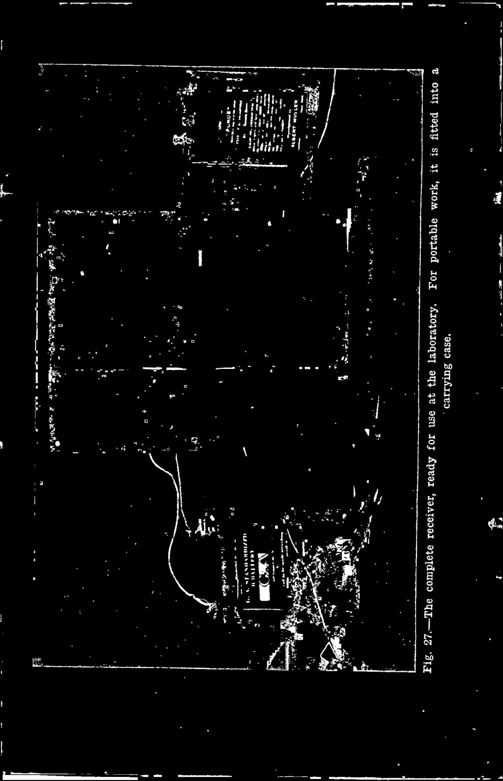
64 Construction of a Portable Receiver 63 To minimize space and weight, it was decided to have a mfd. condenser in shunt with the tuning inductance. The G.A. Standardized type was chosen because the minimum capacity was practically zero, and the maximum mfd. This condenser, in shunt with the antenna of mfd., gives a capacity range from to mfd. Then the inductance steps, to cover 200 to 2,000 meters, were : Capacity to mfd. 90,000 cms.-179 to 473 meters 400,000 ems to 997 meters 1,800,000 ems to 2,116 meters A little figuring showed that with a three -bank winding of 3 x 16 No. 38 D.S.C. high frequency cable, 18 turns per inch, on a tube 31/2 ins. in diameter, the tapping points were : 90,000 ems., 22 turns 400,000 ems., 57 turns 1,800,000 ems., 157 turns The length from the start of the winding to the taps were: 90,000 ems., 0.40 in. 400,000 ems., 1.05 in. 1,800,000 ems., 2.90 in. When the coil was mounted, the zero end was put at the left, looking at the front of the panel, so that, to increase the inductance, the switch was turned clockwise. When the coil was wound, the panel was laid out and all holes drilled before anything was assembled. Fig. 29 shows a very useful fixture made to insure the accurate location of the holes at the corners. A sheet of No. 30 sheet brass was carefully marked with a 5 in. square, and punch marks made 1/4 in. in from the sides at the corners. When the panels were laid out it was only necessary to clamp the brass sheet on a panel and punch the centers. This


65 64 Radio Phone and Telegraph Receivers was important, for, otherwise, the panels would not have fitted together properly. The coil mounting was very simple. Two lengths of brass tubing 3/16 in. inside diameter and 3/4 in. long were cut up and placed l Fig. 31.-A side view of the rheostat with the connection panel linked on. on 8-32 machine screws which go from the front of the panel to the coil. Washers were put on the screws inside and outside the tube so that the brass tubing and the nuts would not cut in. Other details can be seen from the illustrations. Fig. 30 shows the condenser mounting. To secure the condenser to the panel, the screws were removed which originally held the upper end plates to the fixed plates, and longer ones substituted, so


66 Construction of a Portable Receiver 65 that they could be put in the front of the panel. Washers were used to separate the rear of the panel and the top of the end plate. Connections were made to the movable plates by a thin brass Fig. 32.-The mounted socket and grid condenser. strip soldered to the bearing set screw. The other side was soldered to one of the screws holding the fixed plates. An A. H. Corwin dial, slightly modified, was put on the shaft. A hole 3/16 in. in diameter was drilled part way from the back toward the front, s/g in. deep. Then the hole was continued with


67 66 Radio Phone and Telegraph Receivers a No. 26 drill, and countersunk at the front of the handle. The condenser is made with a hole in the end of the shaft threaded When a 6-32 screw was put in the handle and turned into the shaft, it drew on the handle, clamping it securely. The depth of hole must be determined accurately so that the handle will not go on too far before it is stopped at the smaller hole. The unusual strength and permanence of the design of this type makes it particularly well suited to portable work. A departure from the usual rheostat was employed in this set, principally because the porcelain base type was too large for a panel 21/2 ins. wide. The resistance element was simply No. 24 s.s.c. copper wire wound on a tube 3 ins. in diameter. The coil was 11/4 ins. long. To make it non -inductive, the direction of winding was reversed every 1/4 in. A spring washer was put on the shaft of the adjusting handle, with a nut soldered to the shaft to keep a tension on the handle. Two more nuts held a brass contact which, at the maximum resistance end of the coil, slipped off the winding and opened the circuit. The audion mounting and grid condenser were put on a 5 x 2y2 in. panel. Any type of socket could have been used, but the one shown was employed because it had been made up already. Two small angles of 3/8 x 1/16 in. brass strip held it to the panel. Connections to the filament were made by Fahnestock clips put on the screws which held the tube contacts. The plate contact was wired to another clip, and the grid to one side of the condenser. The condenser was made up of five sheets of No. 30 brass, 11/2 ins. long and 1 in. wide, separated by paraffined paper. Two small bakelite plates secured the condenser in position. Fahnestock clips were mounted at the front of the connection panel to take the telephone cord tips. Another pair at the rear i were for the B battery. s This section is shown clearly in Figs. 27 and Obviously, it was not practical to use a 5 -lb. Navy size B battery


68 s Construction of a Portable Receiver 67 with this set. The small Signal Corps type gave results entirely satisfactory and saved 4 lbs. in weight. Two 2 -volt 10 -ampere-hour Porox storage cells were decided upon, as their weight, filled, was only 2 lbs. each. The dimensions of the batteries shown in Fig. 27 were 31/2 ins. long, 11/2 ins. wide, and 4% ins. high over the binding posts. These cells operated the audion for 9 hours at a charge, and have stood up so that they promise to last indefinitely. The wiring of the audion plate and filament circuits were of the usual sort. With a Marconi or VT1, no adjustment of the plate voltage was needed, operating the tube on a 22.5 volt battery. Looking at the rear of the set, the antenna was connected to the right-hand post wired to the coil, the ground to the condenser post at the left; then a wire was run from the left condenser post to the left of the coil, and the right condenser post to the right of the coil. Finally, a wire from the grid was run to the antenna connection, and one from the filament to the ground post.

69 CHAPTER IX CRYSTAL RECEIVER FOR 200 TO 600 METERS A novice or experimenter starting in wireless work should use simple circuits at the beginning until he is thoroughly acquainted with the various elementary phases of wireless work. There is also a demand among the more advanced radio men for a simple set which can be depended upon to work for a short range of wavelengths under all conditions. The set described in this chapter is intended to operate on an antenna of to mfd., giving wavelengths between 200 and 600 meters. This range is extended to 900 meters for the maximum antenna and reduced to a minimum value of 120 meters for the small antenna. The points in designing which are brought out particularly are simplicity and rigidity of construction. It will be seen from the drawings that this is a single -tuned circuit comprising an inductance of 400,000 ems., with two sets of switches and a crystal detector. Binding posts are supplied for the phones and antenna and ground. A fixed condenser to shunt around the telephones should be mounted in the case. The inductance switch is fitted with a handle and scale which revolves at a ratio of 1 :8 of the handle. The necessity for this reduction is that there is considerable work required of the arm on the small -step switch in turning the disc on the large -step switch. This will be more completely described later on. The detector is made up of a handle and plate which fits over an opening in the panel. A spring large enough to extend beyond the hole in all positions maintains the plate against the front of the panel. The outer tube fastened to the plate keeps the tension on 68 e s


70 Crystal Receiver for 200 to G00 Meters 69


71 70 Radio Phone and Telegraph Receivers


72 Crystal Receiver for 200 to 600 Meters 71 the shaft carrying the detector contacts so that the handle will stay in place when pressed inwardly to put pressure on the crystal. By mounting the detector in this manner it is protected from dust and injury while the set is being moved about. Fig. 33, a, b, e and d shows the front of the panel, the rear of LEFT NAND END Fig Details of receiver for short wave traffic, specially designed for dependability and continuous use. the panel with the coil removed, the left-hand end in which the tube is mounted in place, and the switch plate supports removed to give a better view of the interior, and sections through the detector and switch. The panel is 71/2 in. x 5 in. x 1/4 in. thick. Holes are provided to hold it to the case. Detailed drawings have not been given of the detector since this is a comparatively simple mechanism. The handle bears a shaft


73 72 Radio Phone and Telegraph Receivers carrying a small chuck for the contact wire. Screwed to the plate by two 2-56 machine screws is a tube with a groove turned in the outer end. The extreme of this end is turned to a wall 1/64 in. thick and slotted. Then, if this portion is pressed slightly, it will keep an even friction on the shaft. The outer tube is 3/8 in. in SECTIOI' Tt1qU TUNER SECTIO.`_ THRU DETECTOR Fig. 33D.-Details of receiver for short wave traffic, specially designed for dependability and continuous use. diameter. The hole in the panel is 1 in. in diameter, so that a spring 2 ins. long is needed to extend well over the edge of the hole in all positions of the detector shaft. No. 26 gauge spring brass is most suitable for the tension spring. It should be noted that the standardized method of securing handles is used in this case. A plate 21/2 ins, in diameter carries the detector cup. A space of


74 Crystal Receiver for 200 to 600 Meters 73 6/g in. between the plate and the rear of the panel allows sufficient room for the adjustment of the detector wire. By using a plate of this size the appearance of the set is improved by hiding the interior except the space around the opening through which the movement of the wire can be observed. The inductance switch may seem somewhat complicated, but it has the advantage over the simple geared types of causing the large -step switch to jump immediately when the small -step switch moves from maximum to minimum, instead of moving slowly and short-circuiting the large -steps during that part of the range. Details of the inductance switch are given in Fig. 34. Numbers of Fig. 34 correspond to those in the cross-sectional view in Fig. 33d. The inductance is 3 in. in diameter, wound with 74 turns of No. 24 single silk covered wire. Taps are taken off as indicated at actual turns in Fig. 34. The designation numbers are those shown on the dimension drawing of the switch plate. The handle is fastened in the standardized manner to the shaft 6 moving in the brass bearing 9. On the shaft is a gear 10 with a 3/16 in. shoulder secured by two 6-32 set screws. This gear has 20 teeth of 48 pitch giving a pitch diameter of 5/12 inch. The indicating plate is secured to the bearing 5 by four 2-56 machine screws. At the rear end of 5 is a gear 11, held by two 6-32 set screws. This gear has 48 teeth of 48 pitch, giving a pitch diameter of 1 in. There should be a running fit between 5 and 6. Working against the two gears named are two other gears secured to 7. Gear 1 operating against 10 has a pitch diameter of 5/6 in. with 40 teeth of 48 pitch. Gear 2 is also made fast to 7. It has 12 teeth, 48 pitch, giving a pitch diameter of 1/4 in. When the handle is turned gear 10 rotates gears 1 and 2. Gear 11 is turned by 2, rotating the indicating dial. Thus, 1 revolves once to every two revolutions of the handle. This gives the extra force necessary to operate the large -step switch. Since four revolutions of 1 are required for the entire range of inductance the ratio between 2 and 11 is 4 :1. The shaft 7 turning in the bushing 9 carries at the rear end a


75 74 Radio Phone and Telegraph Receivers


76 Crystal Receiver for 200 to 600 Meters ply contact and an arm with a pin which engages in the slots on 12. It is necessary to follow accurately the dimensions shown in the drawing to make the pin on 3 engage perfectly with the Bakelite disc. In laying ont 12, the holes indicated by the light -line circles should be drilled first and the corners filed at an angle of 45 to a radial line through the center of the hole. Then holes for the bottom of the slots should be drilled and the sides filed smooth. This disc is secured to 16 by three 2-56 machine screws. Beneath 12 is a washer sitting on the 4 -ply switch. To take up the strain when the switch is rotating a brass bearing 13 is inserted in the plate. Then an 8-32 machine screw and washer 14 are put into the end of 16. This holds the switch securely. The entire panel is held by four pillars, 4, and 8-32 machine screws. No diagram has been given because experimenters generally wish to change around their circuits to try out different methods. Additional dimensions have been omitted because experimenters generally prefer to work out details according to their own ideas. However, the parts aside from the inductance switch are sufficiently simple that specific details are not required. A set of this type will give sharp tuning and operate quite satisfactorily for amateur communications or the reception of short-wave commercial stations. Since a large proportion of traffic is handled at wavelengths of 600 meters or below this set is well adapted for the regular work of receiving signals.

77 CHAPTER X THE USE OF CONCENTRATED INDUCTANCE COILS Although experimenters are nearly all familiar with the duo lateral or honeycomb type of inductance coil, so called because of the criss-cross appearance of the winding, there seems to be some misunderstanding as to the method of selecting the coils and of their use. This type of coil offers such advantages that this chapter has been prepared to clear up any difficulties connected with the honeycomb or duo lateral coils. In the first place, these inductances, Fig. 35, are wound in a selfsupporting manner, similar to a ball of string. They are of a standard width, 1 in., a standard inside diameter of 2 ins., and vary from 21/4 to 41/2 ins., outside diameter. Each coil is fitted with a plug to connect with a corresponding one on the coil mounting. Sixteen different sizes are furnished in standard inductance values. There are no taps. This may appear to be a disadvantage, yet actually, this is the only way to obviate dead ends and unused turns in the field of an active coil. Moreover, with primary and secondary tuning condensers a large wavelength range can be covered without changing coils. The honeycomb inductance is also applicable to directly coupled receiving circuits, wavemeters, oscillators and low -powered vacuum tube transmitters. Test on this type of winding show the high frequency resistance to be unusually low for the long wavelengths and the distributed capacity, negligible, making them particularly well adapted for use with wavemeters. A tuner for damped or undamped waves, built up from these coils and a variation of the standard mounting is illustrated in Fig. 36. By the proper selection of condensers and inductances, how - 76


78 The Use of Concentrated Inductance Coils 77 ever, it will tune to wavelengths from 150 to 30,000 meters. The coils shown, however, with condensers of mfd. maximum, will tune to 6,500 to 15,000 meters. The method for determining the 2 Fig. 35.-Showing how the honeycomb coils are made up on plugs for mounting. sizes of the condensers and inductances for any wavelength range is discussed later in this chapter. In comparison to the large tubular inductances required for long wave reception, these coils are very convenient and easy to work into a small receiving set. In designing this panel, the intention was to use the tuner for long wave reception only, so that no special provisions were made for changing coils. However, if the panel is not set into a case, changes can be effected readily.


79


80 The Use of Concentrated Inductance Coils 79 The original coil mounting was arranged so that the coils would be at the front. It will be seen from Fig. 37 that the center plug is stationary, while the other two are pivoted. This mountain was intended to be used for a balanced circuit, but it can be made into a feed-back tuner by using the center coil as the secondary, one outside coil for the primary, and the other for the tickler. Variable inductive coupling to the secondary can be obtained by moving the primary coil on its pivot, and tickler coupling by swinging the tickler coil. Fig. 38 shows how the mounting was changed to make possible the adjustment of the coils from the front of the panel. The shafts of the movable plugs were removed by taking the pins out. Then two shafts were turned of brass to the diameter of the others, with a small shoulder at the upper ends. These ends were tapped with an 8-32 thread. Secured to the shafts by means of 8-32 screws are the bakelite discs which serve as handles. A long slot in the panel allows the handles to protrude far enough that they can be turned readily by the thumb. Four screws, as will be seen from the illustrations, are required to fasten the plug unit to the panel. If desired, pointers can be put under the heads of the two upper screws and bent in such a way as to indicate against scales on the edges or upper surfaces of the disc. In this case only 90 scales are required. No diagram of connections is given here, for the individual experimenter will prefer to choose his own. - It is sufficient to say that the center coil is the secondary, one outer coil the primary, and the other the tickler. If no tickler is needed, a two -coil mounting can be used with only one movable inductance. A number of experimenters have inquired about the use and selection of these coils, and appeared rather dismayed when they were informed that they must do a little figuring to find out. One of the great advantages of these coils is that, with two or three formulas, it is possible to tell accurately to what wavelengths they will tune. Where there is no way to determine the capacity of an antenna,


81 5.0


82 The Use of Concentrated Inductance Coils 81 the value mfd. can be taken as an approximation, and substituted for the value of Cant in the following equations. For sharp tuning, the primary circuit should have a series condenser in the antenna lead. This decreases the effective capacity range, for the antenna acts as a second condenser in series with the tuning condenser, making the effective capacity at any adjustment of the tuning condenser. where Cef1 1 1 Cant + Cpri Cell = effective capacity of the circuit, Cant= capacity of the antenna. and Cpri = capacity of the tuning condenser. A primary condenser shunted around the inductance gives a larger wavelength variation, but broader tuning. Then (1) Ceff = Cant + Cpri (2) The wavelength to which the antenna circuit will respond depends upon the effective capacity and the inductance of the tuning coil. Antenna inductance can be neglected. Hence the wavelength of the circuit will be a = 59.6 AIL C (3) or L = 3552 C or C = 3552 L where x = wavelength in meters, L = inductance in ems., and C = effective capacity in mfds. (4) (5)


83 82 Radio Phone and Telegraph Receivers It is well to remember that 1 henry equals 1,000,000,000 ems., and 1 millihenry equals 1,000,000 ems. Since the only one condenser is used in the secondary circuit for tuning, the single condenser, shunted across the secondary circuit. Fig. 38.-A new shaft, carrying a bakelite disc, was substituted for the other, so that the coils could be mounted behind the panel and moved from the front. Hence, it is not necessary to make a separate calculation for effective capacity as with the antenna circuit. The wavelength, therefore, is simply x=59.6-nilc (6) where the factors are the same as in (3). The curves in Figs. 39 and 40 show the wavelength ranges of each' of the standard honeycomb coils with capacities from to mfd. This simplifies the design of the circuits, making unnecessary the use of formulas (3), (4), (5) and (6).


84 The Use of Concentrated Inductance Coils 83 To work out an actual problem, suppose we wish to tune for 200 to 4,000 meters, with an antenna of mfd. and a tuning condenser of to mfd. The most approved method is to use the condenser in series with enough Coils to give the required wavelength. Then the first problem is to determine the effective capacity range. Since the series condenser should not be used at a value below 0.5 of the antenna capacity, in this case mfd.. The effective minimum capacity will be : At maximum Ceti = x 3 or Cf min. = mfd. C eff or Cyr max.= mfd. Since mfd. is the minimum effective capacity and 200, meters the minimum wavelength, we must find a coil which, allowing a small margin, will give 200 meters under this condition. From Fig. 39 the required coil is found to be mh. With this coil and the maximum effective capacity, mfd., this coil gives 275 meters. _In overlap in wavelength of 20% is generally allowed. An examination of the curve shows that, at minimum capacity, the 0.15 mh. coil gives 250 meters and at mfd., this coil gives 275 meters. Following this process, it will be found that to cover the 1


85 84 Radio Phone and Telegraph Receivers o U `.i{ ç i.? Ç r- d i N rr'.4iirrri :.:: e 0 0 m N g ó.spo,o}o.o iw R+ooao7 a^tt'al,t3 0


86 The Use of Concentrated Inductance Coils 85 range from 200 to 5,000 meters, coils are required of 0.075, 0.15, 0.3, 0.06, 1.3, 2.3, 4.5, 11.0 and 20.0 mh. The larger the tuning condenser, the fewer coils required. Another method of designing the antenna circuit is to use a variable condenser around the inductance. This cuts down the number of coils required, but has the slight disadvantage of broader tuning 1 than is obtained by the series condenser. Now according to (2), if we use the same antenna of mfd. and tuning condenser of to 0.01 mfd., the effective capacity range will be or, at minimum, and, at maximum, Calf = Cant + Cpri = , = mfd. = , = mfd. Fig. 39 shows that, with these limits, the lowest wavelength obtainable with the standard coils is 250. Going up to 5,000 meters, coils of 0.04, 0.075, 0.15, 0.3, 0.6, 1.3, 2.3 and 4.5 mh. are needed. This makes possible the use of fewer and smaller coils. Still another method is that using a series, parallel condenser switch, so that the tuning condenser can be put in series or parallel with the coil. Here, then, we have a capacity range of to mfd., and to mfd. With the aid of Figs. 39 and 40, a table like this can be made. Inductance Series Parallel mh m m mh m m mh ,190 m. 1,500-2,540 m. 2.3 mh. 1,020-1,575 m. 2,000-3,400 m. 6.5 mh. 1,750-2,650 m. 3,400-5,700 m.


87 :: Radio Phone and Telegraph Receivers z.:. j._..:._.:...,. N N - o ó ó o 0 $ a S S ó 0 ö 0 ó ó 0 0 spninjo.o.y,jm R{nodojam}'a333


88 The Use of Concentrated Inductance Coils 87 This does not give a perfect overlap of wavelengths, but the range is well enough covered for all practical purposes. In designing a circuit, it is always well to take the maximum and minimum capacities of a tuning condenser at 10 and 90 of a 100 scale. The secondary circuit is easy to design, for there is no antenna capacity to complicate matters. If, as in the previous example, a range of 200 to 4,000 meters is required, and a to mfd. condenser is used, the inductances needed as shown in Fig. 39 are 0.04, 0.15, 0.6 and 4.5 mh. If the condenser of 0.01 mfd. is connected across the telephones and B battery, a small tickler coil is required. For long wavelengths up to 25,000 meters, a coil of 6.5 mh. is large enough. For meter reception, a 0.04 coil can be used. The size of tickler coil can be determined experimentally as it depends on the tubes used and other circuit conditions. There is no definite relation between the tickler inductance and the wavelength of the secondary circuit. Part of the misunderstanding connected with the use of these coils is due to their new and different construction. It should be remembered that these coils do anything that other coils do.

89 CHAPTER XI A SIMPLE REGENERATOR RECEIVER Now that the experimenters are getting on the scratch line for the long distance, short wave work for which everyone is preparing, every man wants a regenerative set. There is a certain amount of choice between various circuits in use at present, but if the majority favors the type using no condenser in the secondary, it is probably because the manufacturers have specialized on it. While we are on the subject of the variometer-tuned secondary set, it might be well to clear up a question that seems to lurk unspoken in the minds of many experimenters-a sort of skeleton in the closet question, ignorance of which no one wants to admit. "What does the secondary variometer do? How can it tune the circuit to a given wavelength, when there is no capacity in the circuit?" Yet the variometer does tune, and very sharply. The answer is simply this : The condenser effect between the grid and filament furnishes the capacity, a small amount, about mfd., but enough to make the secondary circuit oscillatory. To tune to 300 meters with such a capacity, requires only 1.3 mh. inductance. Because the tube is depended upon to furnish the capacity, a large variation in inductance is required to cover any considerable wavelength range. Since only a part of the inductance is adjustable, the balance acting as the coupling coil, the variation of the inductance and, consequently, the wavelength range, is quite limited. Therefore, to make the set of wider utility, the equipment described in this article is designed to operate with a mfd. variable condenser in the secondary circuit. Again, a straight tickler coil is employed instead of a tuned 88


90 ir


91


92 90 Radio Phone and Telegraph Receivers plate circuit. The reason is a constructional one. A tickler is much easier to make than a variometer. Figs. 41 and 42 show the front and rear of the receiver, mounted on a panel 5 by 10 3/16 ins., with a complete circuit in Fig. 43. In the primary, the thirteen taps give a wavelength range, with a mfd. antenna, up to 600 meters. On the first secondary tap, a mfd. condenser will give a range of approximately 150 to 450 meters, and on the second tap, 250 to 700 meters. Thus the set is adapted not only to 200 -meter work, but to the reception of meter commercial stations as well. In the plate circuit of the audion the tickler is connected, preferably with a mfd. fixed condenser around the telephones and B battery, although this is not shown. A tube 31/2 iris. in diameter and 21/4 ins. long is needed for the primary coil. This is wound for 1.7 ins, with 20 No. 38 high frequency cable, giving 38 turns per inch, or a total of 65 turns. These are tapped as follows : Tap 1..15th turn Tap 2..18th turn.. Tap 3..21st turn Tap 4..24th turn Tap 5..27th turn Tap th turn Tap th turn Tap 8..40th turn Tap 9..45thturn Tap th turn Tap th turn Tap th turn Tap th turn Two methods of tapping can be employed. One is to wind the coils without taps. Then mark with ink where the taps should be. Unwind the wire, scrape at each marked point, and solder on leads. The other way is to bring out a loop for each tap, and tie a knot in the loop. This holds the wire securely at the tapping point while the coil is being wound. When the work is completed, the loops are cut to the proper length and soldered to the switch points. A better method is to make short loops, and use No,.. I bare copper wire leads to the points and other connections.


93 A Simple Regenerator Receiver 91 Short threaded brass pillars or angles of %- by 1/16 -in. brass strip can be used to mount the primary tube. This must be accurately and securely fixed. Otherwise, because of the small clearance, the secondary coil will touch the primary tube. The construction of the secondary coupling coil and tickler are identical, both as to the method of mounting and the size of the coils. The tubes are 3 ins. in diameter, and 11/4 ins. long, wound with 20 No. 38 high frequency cable Each section is 3/8 in. long, with a separation of 3/8 in. between them. If the bearing at the panel is carefully made, no rear support will be required for the shaft of either the 'coupling or tickler coil. For each coil, two brass washers, 3/4 in. in diameter and 3/16 in. thick, are cut and threaded at the center -,with an 8-32 tap. The brass shaft, of 3/16 in. rod, is threaded at one end for a distance great enough to take one washer, the adjusting knob, and a nut to clamp the handle against the washer. Then,,. from the other end, the rod is threaded to within the thickness of the panel from the other threads. The washer under the handle bears against the front of the panel, while the other washer bears against the rear, leaving the unthreaded part of the rod to run in the hole in the panel. A lock nut holds the rear washer in place, and maintains a small amount of friction. Two sets of nuts holds the coil in position on the shaft. Leads, run in Empire or soft tubing, can be wound around the shaft and brought off to the terminals. The secondary leading coil, in series with the coupling coil, provided coupling to the tickler, independent of the primary -secondary coupling. The tube is 13/4 ins. in diameter, wound for 1 in. with 20 No. 38 cable. Starting at the rear end near the tickler, a tap is takes off at the tenth turn, and connected to the first póint of the secondary switch, as can be seen in Fig. 43. This coil should be mounted in a manner similar to that used for the primary. With this coil completed and in place, and the refully connected with No. 14 bare copper wire, all joints the set is ready for use. A condenser, mounted as shown


![II11111IE111 2.111i01111,11I111III111111IIIIIr (]IIIII1 `I 11 I1](/docs-images/87/97369327/images/94-2.jpg ",1! I.IYJ111 1111 II' 1 IL.OIA_,... 1111 WII111 n 11,.,,. 1,.,1,,,.")
94 I lill, IIIIII I11III Iii MO _,._,,..,,,,,,,.n.a,.,íi.m..um1.1d :;..._.._ un11111ianlllilphunr m EARI I no! ;; ^; I á Iuilulml 111 IIIIIIIQIIMIUMII Imlluuln R 11 I II11111IE i01111,11I111III111111IIIIIr (]IIIII1 `I 11 I1,1! I.IYJ II' 1 IL.OIA_, WII111 n 11,.,,. 1,.,1,,,..,1,, : ' n u 1E 0 i, m 'I'll" II s1111a I < ill =_ M 0.1


95 2 A Simple Regenerator Receiver 93 in some of the preceding chapters, and a vacuum tube mounting, complete the set. If 5- by 5 -in. panels are used for the audion and condenser, the set can be made up neatly with the 5- by 10 -in. panels below, and the two smaller ones above. Tuning in the primary circuit, accomplished by the 13 -point switch, will be found quite sharp. The secondary condenser, giv- h..1i1i1i1 - Lio_T Fig. 43.-Connections for the regenerative receiver. ing a facile control over a considerable range, saves just the amount of time which, with a receiver less easy to handle, causes the loss of a call. The coupling to the primary is usually made tight for listening -in, and loosened for sharp tuning. If the tickler leads are of the correct polarity, regeneration can be readily adjusted, and will need practically no changing from 200 to 600 meters, another advantage over the tuned plate circuit which must be fixed for each signal. Complaints about poor operation can often be traced to wornout B batteries. When anything goes wrong, the plate batteries should be examined first of all.


96 CHAPTER XII. c VARIOMETER TYPE REGENERATIVE RECEIVER There is one mandate which must be observed in designing a regenerative set of the variometer type-"know your variometers." In order to give the readers of this book accurate data on this kind of set, careful tests were made on the Radio Shop variometers, as these were of excellent and typical construction. The values given are accurate within 3 to 5 per cent, an allowable variation for all practical use in design work. First off, the mechanical dimensions were taken. The variometer stator was 4 15/16 ins, square, and each wooden half 11/e ins. thick, with a separation of 1/2 in. Each side was wound with 26 turns of No. 20 D. C. C. wire. The rotor measured 37/8 ins. in diameter and 2% ins, thick, with 27 turns of No. 20 D. C. C. wire on each side. Terminals of the rotor were soldered to the shaft, which is open in the center. Connection to the shaft was made through large brass bearing blocks, fitted with springs which maintained a constant pressure against the shaft. The true inductance, making the necessary allowance for distributed capacity, was calculated as 31,000 ems, at minimum, and 538,000 ems. at maximum, giving a ratio of 1 to 17. Although the variocoupler was not used in the set described in this chapter, its constants will be given. The base was 5 ins. square, on which was mounted a tube 4 ins. in diameter, wound with No. 20 D. C. C. wire. It was tapped at the 8th, 15th, 22nd, 30th, 37th and 94


97 Variometer Type Regenerative Receiver 95 X


98 96 Radio Phone and Telegraph Receivers wriz,


99 2 Variometer Type Regenerative Receiver 97 45th turns. Connected with a capacity of mfd., the average antenna capacity, the wavelength was : and with mfd. it was: Tap Wavelength m Tap Wavelength m The coupling ball of the variocoupler was 31/2 ins. in diameter and 1% ins. thick, wound on each side with 14 turns of No. 20 D. C. C. wire. Fig. 44 shows the circuit used in the preliminary tests. In the grid circuit the variometer is in series with the coupling ballshown as a tubular inductance-and a coil of two turns which provided coupling to the buzzer -excited wavemeter. Resonance with the wavemeter was obtained by adjusting the grid and plate variometer until the signals were sharp and clear. No trouble from howling was noticed, although the variometers were separated only 3 inches. The wavelength with a VT1 tube, and 140 to 340 with a Marconi type detector. Next, one variometer was connected as in the lower diagram of Fig. 44A. This was to show that variometer, with the capacity between the grid and filament, actually form an oscillatory circuit.


100 98 Radio Phone and Telegraph Receivers Fig. 45-Details of the audion and plate variometer mounting.


101 Variometer Type Regenerative Receiver 99 At first it was not possible to find a resonance point, for the sound in the telephones was the same over the range of the wave - meter. In fact, it seems as if there was no tuning in the circuit. Loosening the coupling only weakened the signals. Finally, a piece of Advance resistance wire, with an adjustable contact, was put in series with the buzzer. The resistance was increased until the 1 buzzer barely vibrated. Under this condition a sharp resonance point was found without difficulty. With a VT1 the wavelength range, at minimum and maximum on the variometer was less than 140 to 300 meters, and with a Marconi tube, less than 140 to 290 meters. This was expected, as the elements in the VT1 are much larger than in the other tube. Another test was made to determine the relative settings of the grid and plate variometers, for maximum amplification, over the wavelength range. A large coupling coil to the wavemeter was used, with connections as in the diagram of Fig. 44A. The following readings were taken: Wavelength GVMR PVMR 200m With the data given above, the design of a complete receiver was undertaken. The last table given showed that, in the secondary, no difficulty would be experienced in making the secondary circuit oscillate over a range of 200 to 350 meters. Since the set was designed especially for 200 -meter reception, it seemed unnecessary to include a condenser for longer wavelengths. However, a condenser was used in the primary circuit, as an experimental set-up showed that tuning in this way was more easily accomplished. The switch 51 55


102 100 Radio Phone and Telegraph Receivers once set, according to the antenna capacity, only the condenser was used for tuning. Bakelite panels, 5 to 10 inches, were used, instead of the 5 by 5 inch ones, for the practical reason that the variometers were too _-}- -=- Fig. 46.-Details of the audion and plate variometer mounting.


 Fig. 47.")
103 Variomcter Type Regenerative Receiver 101 large for the smaller panels. Instruments of the same circuit were put on one panel, that is, the primary loading coil and condenser, the secondary variometer and coupling coil, and the vacuum tube i O I) Fig. 47.-On ti e secondary panel are mounted the coupling coil and grid variometer. One-half scale.


104 102 Radio Phone and Telegraph Receivers and plate variometer. The improved method of mounting the binding posts is shown. Fig. 45 shows the rear, and Fig. 46 the side of the tube panel. The plate variometer is mounted directly behind the panel, held in place by wood screws, put in from the front. Any indicating dial can be used, according to the discretion of the builder. Above the variometer are the rheostat and tube socket, the latter supported on two brackets of %- by 1/16 in. brass strip. The grid condenser and leak, as well as the phone condenser, shown in Fig. 44B, can be mounted on the top of the variometer stator. Two 6 13/16 -in. lengths of 13/16 -in, square brass rods hold the terminal panel, which is of 1/8 -in. bakelite, 21/2 by 4 7/16 ins. The rods were threaded with a 6-32 tap at both ends. Because of the large size of the Radio Shop variocouplers, the rotor was taken out and used with a small primary coupling coil, Fig. 47. No taps were needed, as a condenser gave the fine adjustment. The variometer was mounted as in Figs. 45 and 46. The primary coil was wound on a tube 4 ins. in diameter and 1/ ins. long, with 25 turns of No. 24 S.S.C. wire. Brackets of 3/s- by 1/16 -in. brass strip were made to hold the tube to the panel. An interesting method of locating the holes for the rotor shaft was employed. Obviously the rotor would touch if the holes were off center. The tube was placed on a sheet of ordinary ruled paper, such as is used for note books. Then it was removed until one of the lines passed through the center of the tube. Marks were made on the tube where it intersected the line, and extensions drawn up 3/8 in. Thus the holes were located diametrically. Flexible leads provided connections to the rotor winding. Fig. 48 shows the primary panel, made up of a mfd. Chelsea condenser and the primary loading coil. This condenser is particularly recommended, both for its mechanical and electrical advantages. The insulation is good, the construction rigid, and the price reasonable. A counterbalance offsets any tendency for the variable plates to rotate of their own accord.

![BO i IN PRI L]GL- Fig 48](/docs-images/87/97369327/images/105-1.jpg "-The antenna loading coil")

105 Variometer Type Regenerative Receiver 103 BO i IN PRI L]GL- Fig 48 -The antenna loading coil and mfd. condenser are carried on the primary panel. One-half scale.


106 104 Radio Phone and Telegraph Receivers Above the condenser is a loading coil made of 60 turns of No. 24 S.S.C. wire, wound on a tube 3 ins, in diameter and 21/2 ins. long. A tap at the center was run to the primary switch, as shown in Fig. 44B. No connections from the instruments to the binding posts have been shown in these illustrations, but they can be determined easily from the wiring diagram. This receiver, according to the adjustment of the plate and coupling, will receive damped, undamped, and telephone signals. Damped signals are easy to tune in, but the other two require some knowledge of operation. Both telephone and undamped signals are first distinguished, usually, by the supply current hum. Then a slight detuning, either by the coupling, primary condenser, or plate variometer bring in the signals sharply. If the removal of the hand from the knob causes any change in the signals, it is better to detune with the primary condenser.

107 CHAPTER XIII. TWO-STEP AUDIO FREQUENCY AMPLIFIER The amplifier, to many experimenters, represents a more difficult problem than it really is, though there are important points which must not be overlooked. The two-step type, described in this chapter was built in my laboratory so that experimenters might see what can be done in the way of an efficient instrument, designed to fit the financial resources and the shop equipment of the average radio man. Given the elements of an amplifier, the tubes and sockets, transformers, rheostats, and jacks, there are almost as many ways of arranging them as there are constructors. In the drafting room, a designer must justify every part of his layout. If experimenters would put themselves to this test, making themselves show a reason for each step they take as they plan an instrument, they would be surprised in the improvement both in the appearance and results of their apparatus. The mere fact that a thing "fits" does not justify its place in the design. Particularly in planning an amplifier, the circuit must be considered and given an equal weight with the other factors. If leads are run back and forth over the set there is sure to be trouble from howling because of the feed-back effects which will occur between the grid and plate circuits. On some equipment, elaborate precautions are taken with grounded shields between the steps, but no trouble was experienced in this set. The criticism may be made that biasing resistances, transformer condensers, and other details have been omitted. The answer is simply that this set worked as well as a manufactured amplifier 105


108 106 Radio Phone and Telegraph Receivers


109 Two -Step Audio Frequency Amplifier 107 which was equipped with those things, and cost more than six times as much as it did to make this one. Fig. 49 shows the front of the panel, on which are the rheostats, jacks, and observation windòws. The upper jack, of the double circuit type, allows the telephones to be inserted directly in the plate Fig. 50.-Rear view, showing the terminals for outside connections, carried on a separate bakelite panel. circuit of the detector. The lower jack, at the left, is for the first step, and the third, at the right, is for the second step. A bakelite panel, 5 by 10 by 1/8 in., was used for the panel. Arrows above the rheostat handles indicate the direction of turning for increased resistance. It should be noted that the clock -wise direction is used in standard practice, for increasing whatever is controlled. No pointers were used as, for this purpose, they are not essential and only add to the work. On the rear, as can be seen from Figs. 50 and 51, are the instruments which make up the completed amplifier. Practically all amplifiers are equipped with telephone jacks in-


110 108 Radio Phone and Telegraph Receivers


111 Two -Step Audio Frequency Amplifier 109 stead of binding posts. They permit a quick ehange from one step to another, and can be used to change circuits which would otherwise require elaborate switches. The jacks used for this set are of the Federal type. The detector jack is of the double circuit construction, as shown in Fig. 54. Both the first and second steps are closed circuit types, although Fig. 52.-Notice the construction of the rheostats and the way in which, they are supported. The posts which hold the transformers also act as stops for the rheostat contact arms. it is better to use an open circuit jack for the second step. Then, though the filament of the second tube is lighted, no plate current will be consumed by that tube when only the first step is being used. Because a 1/8 -in. panel was used, a little trouble was experienced in mounting the jacks. This was overcome by making the holes in the panel only large enough to take the threaded portions of the front nuts, instead of the regular way with the hexagonal parts flush with the panels. This can be seen from the side views, Fig. 51. Half a dozen different kinds of rheostats were tried and found unsatisfactory before the type finally adopted was worked out.


112 110 Radio Phone and Telegraph Receivers Rheostats are expensive and most of them take up considerable space on the panel. This design, shown in Figs. 51 and 52, is very simple and fitted in nicely with the other instruments. First, two pieces of 1/8 -in. bakelite were cut to a size of 13/4 by 1 in. Then the head of an 8-32 iron screw was eut off, leaving the threaded part 1 in. long. Next, the bakelite was put in a vise, and the screw hammered down on the four corners of the piece. This made a series of regular depressions in the bakelite, in which No. 24 Advance wire was wound. The mounting posts were cut from 3/16 -in, square brass rod, threaded with 6-32 tap for the screws through the panel, and drilled for the screws which hold the resistance units to the posts. The centers of the rheostat handles are just 11/4 ins. below the centers of the supporting posts. This made it possible to use the upper transformer supports as stops for the rheostat contact arms. The contact arms are just short enough so that they clear the resistance element supporting posts, and pass on to the unwound portions of the small bakelite pieces, opening the filament circuits. Flexible leads from the contact arms provide connections to those sides of the rheostats. Looking at them from the front, the resistance windings are open at the right, and connected to the filament circuits at the left. Federal transformers were selected for this set, because of their small size and high efficiency. Still, they were too large to mount directly on the panel without too much crowding. Accordingly, eight pieces, 3/4 in. long, were cut of 1/4- by 3/16 -in. brass tubing. These pieces, put on 8-32 machine screws, act as spacers to hold the transformers back from the panel. This gives the necessary room, under the transformers, for the shafts of the rheostat controls. Also, the binding posts of the transformers are made even with the terminals of the jacks, an advantage in wiring. The four posts hold the transformer as rigidly as if it were directly on the panel. In Fig. 51, the audion sockets can be seen, and Figs. 52 and 53 show the mounting panel. The sockets themselves were made of 15/16 -in. lengths of brass tubing 1% ins. inside diameter. Short


113 Two -Step Audio Frequency Amplifier 111 lengths of threaded rod, soldered to the tubes, were used to hold them down on the mounting panel. A bakelite panel 1/8 -in. thick, 5 ins. long and 21/2 ins. wide, was cut out for the socket mounting. In this piece were drilled the holes for the audion contact pins, socket mounting rods, and contact spring screws. Experimenters who use manufactured audion sock. Fig. 53.-This view shows the brass angles which carry* the tube panel and rear connection panel. 2 ets can readily change the arrangement of the panel without departing from the general idea. To hold the socket panel to the main panel, four brass angles were made from %- by 1/16 -in. strip. Four more were made at the same time to hold the rear connection panel. When holes must be drilled in parts of this sort, it is always advisable to drill them before bending, to make the work easier. These angles are held by the same crews which hold the contact springs, as illustrated in Fig. 53. Connections to the contact springs were soldered to the heads of the screws on the upper side of the panel. This made the wiring


114 112 Radio Phone and Telegraph Receivers easier than it would have been to connect at the bottom, though it called for clever manipulation of the soldering iron. Another 1/8 -in. bakelite panel, 5 by 21/2 ins., was used for the connections. As explained before, it is held by brass angles to the socket mounting panel. Three sets of terminals are provided for o INPUT - B Fig. 54.-Diagram of connections for the two-step amplifier. connections to the input, or plate circuit of the detector, and the A and B batteries. The terminal screws are slightly staggered so that the wires will not interfere with each other. Lacking an engraving machine, the letters were simply scratched deeply and filled with white lead. Paraffine and zinc oxide are easier to handle, but are apt to melt out if the bakelite is heated while the connections are being soldered. One of the easiest ways to spoil the appearance of an instrument is to wire it in a slipshod manner. Good wiring adds greatly to the looks of any apparatus. For this amplifier, No. 14 bare copper wire o


115 Two -Step Audio Frequency Amplifier 113. was used. The wire was first cut to 12 -in, lengths, and rolled' straight between two boards. Then, as each connection was made, the distances were carefully measured, and the wires cut and bent o -o +A - -B+ OUTPUT Fig. 55.-Wiring of the receiver, previously described, with the amplifier. in sharp angles. This process takes a little extra time, but it is well spent. A word of warning :-To judge from the work of some experimenters, the prevalent idea is that a joint must have an ounce of solder to insure a perfect connection. As a matter of fact, a drop is as good as a pound, and looks far better. Where it was necessary to run two wires close together, Empire tubing was slipped over the wire. This was not done throughout, however, because it was not necessary, and Empire tubing is expensive. Fig. 54 gives the amplifier circuit. While it looks simple, there

116 114 Radio Phone and Telegraph Receivers are numerous chances to make mistakes. It is much easier to have the wiring right the first time than to have to hunt trouble and make changes. To use this amplifier with an audion detector, it is only necessary to connect the plate to the input terminal which is joined to the transformer post marked P 2, and the positive terminal of the detector B battery to the Pl side of the transformer. The detector B battery is left in circuit, as no provision is made on the amplifier to supply the detector plate potential. A quick adjustment of the amplifier rheostats puts the set In operation, after the detector has been adjusted. Oftentimes the operation is improved by changing tubes, for, though they are designed to have similar characteristics, vacuum tubes do vary. Fig. 8 gives a wiring diagram of the amplifier used with audion receiver.

117 CHAPTER XIV. BUILDING A RADIO FREQUENCY AMPLIFYING TRANSFORMER Radio experimenters have been slow to take up experimenting with radio frequency amplification, although it has been used commercially for more than two years. The reason is probably found in the fact that nothing has been written, in the wireless publications, on the construction of high frequency transformers. In an audio frequency amplifier, the incoming oscillations are first detected, and the low frequency currents are amplified in the succeeding stages. Therefore, in a set comprising a detector and three - step amplifier, signals can be heard by inserting a pair of telephones in the plate circuit of the detector or any of the amplifier tubes. On the other hand, a radio frequency amplifier may have three steps of amplification and then a detector. Signals can be heard only in the plate circuit of the detector, for radio frequency currents are flowing in the amplifier tubes. It has been found that signals below a certain strength cannot be made audible by any number of audio frequency amplifiers. The radio frequency currents, however, can be amplified to the required strength, at which point they will operate a detector and, if desired, audio frequency amplifiers. There is one disadvantage in the use of radio frequency circuits. 5 That is, radio frequency currents flow in the plate circuits through the transformer. There is a resonance effect due to the inductance of the transformer and the capacity between the plate and the filament of the tube. Consequently, the best results are obtained near the resonance frequency, although the resonance point is not sharp. This particular transformer, with the regular A. P. Tubes, operates from about 1,000 to 5,000 meters. 115


118 116 Radio Phone and Telegraph Receivers' The first radio frequency transformers were made with air cores, the prevalent belief being that the losses in an iron core 'would be prohibitive at high frequencies. As a matter of fact, this proved to be untrue. Moreover, the distortion of telephone signals is less with an iron core transformer than with the air core type. At the beginning, silicon steel in. thick was considered necessary for the laminations. Steel of such a thickness is practically impossible to obtain, particularly in any quantity. Now, laminations up to 0.01 in. in thickness are used on some transformers. The greatest difficulty is in the design of the transformer. First of all, following the present methods, a particular wavelength, at which the amplifier will operate at maximum efficiency, is chosen. With the capacity of the tube the primary of the transformer must form a resonant circuit, one in which the natural period will be that of the signals received. Next, at that frequency, the secondary impedance must equal that of the tube. If 3,000 meters is taken as the optimum wavelength, with a corresponding frequency of 100,000 cycles, at 4,000 meters the plate circuit will not be in resonance, and the resultant frequency of 75,000 cycles will give a lower secondary impedance. Thus it can be seen that the design of a radio frequency transformer, at the present stage of development, is no easy matter. Variations in the steel further complicate matters so that, when the transformer is completed it may not do what was expected of it after all. It is not proposed in this chapter to give absolutely accurate details which will produce a given result that would be out of the question, considering the variations which experimenters are bound to put into their own construction. However, a working basis is provided which will lead to new ideas and developments. Silicon steel for the core can be from to in. thick, preferably of the smaller size. Enough is needed to make a pile 3/8 in. thick. Before the steel is cut a template should be made of brass or steel, the exact size of the laminations, as shown in the detail drawing. Then, when the core pieces have been cut with


119 Building Radio Frequency Amplifying Transformer 117 Fig. 56.-The letters on the assembly refer to the details. This instrument calls for no difficult construction or expensive parts.


120 118 Radio Phone and Telegraph Receivers snips to the approximate size, they should be clamped to the template and filed accurately. The dimensions of the two halves of the core are identical. There is an air gap between the parts when they are put together. Four bakelite strips, marked A, are used to hold the laminations together. Before they are assembled on these strips, one-half of the laminations must be dipped in japan or varnish and hung on wires to dry. Then the plain and japanned laminations are put together alternately. This should make a total thickness, when the core is completed, of 7/16 in. At this point mounting legs should be cut from a brass strip 3/a in. wide by 1/16 in. thick. A cardboard form (Fig. 57), C, is first made to go over the center part of the core. This supports two washers, E, over which a larger paper tube, D, is placed. The progressive assembly in Fig. 57 shows that another set of washers, B, are put over the outer tube. These washers carry the binding posts of the primary and secondary windings. The tube C is made on a wooden mandrel 13/16 in. square. Bond paper about 8 in. wide is wrapped around it and varnished at the center part with Valspar. Enough sheets are used to make the tube about 3/64 in. thick. When completed the paper should be wrapped with string and the whole outfit put in a warm oven to dry. Wide paper is called for here because, if the Valspar leaks out at the edges, it will cause the paper to stick to the mandrel, making its removal impossible. After the drying process the tube should be eut to length before it is taken from the mandrel. Then end washers may be cut with a sharp knife from heavy cardboard to the dimensions given in Fig. 56. If cardboard of sufficient thickness cannot be obtained, several layers can be glued together and dried under pressure. A larger mandrel must be made for the tube D, which carries the winding. This should be treated as explained in the first part of this section. The assembled view in Fig. 56 shows the primary and secondary


121


122 120 Radio Phone and Telegraph Receivers winding on the tube D. Two sections are used for the secondary, with the primary at the center. In the matter of winding the radio frequency transformer is much simpler than the audio frequency type. First, the secondary coils are wound, each section having 90 of turns No. 40 single silk covered wire. The winding is of the ordinary sort secured with Valspar. Connections between the sections should be made inside the tube, and the wires soldered to make a perfect connection. Be sure that both parts of the coil are wound in the same directions, so that they will be equivalent to a continuous winding. The primary requires 105 turns, also of No. 40 single silk covered wire. When the coils are completed, they should be covered with Valspar and baked dry in a warm-not hot-oven. Leads can be brought from the coils directly to the binding posts, or pigtails, secured to the tube, can be used instead. The latter method insures their permanence. The beginning of the secondary should be brought to a terminal marked Sg, and the corresponding end of the primary to a terminal marked Pp. Thus, the Pp end will go to the plate of the radio first frequency audion, and the Sg end of the secondary will be connected to the grid of the next tube. When the parts are ready, the tubes and end pieces should be assembled as shown in Fig. 57. An application of Valspar will keep the parts in place. Then the coil system is put on the core, and the end plates tightened until the laminations are clamped < closely. If the coil mounting is not tight on the core, put á little Valspar on it and put it away to dry out. This varnish is better than glue for holding light parts, for once dry, it does not soften. t

123 CHAPTER XV RADIO AND AUDIO FREQUENCY AMPLIFIER This chapter describes a very interesting combination of a radio and audio frequency amplifier. This unit was built and it proved so successful, that it is felt it will be of service to those who desire to obtain strong signals from stations from which it is now impossible to get good signals. This amplifier is also very well adapted for use with loop antennas. A tuned impedance coupled amplifier employs an inductance and shunt condenser between the output circuit of one tube and the input circuit of the next. The inductance and condenser must be tuned to the wavelength of the incoming signals, to give maximum amplification. In a receiving set using concentrated inductances, the coil and condenser may be identical in size with those in the secondary tuning circuit. If possible, the coupling circuit condenser should not exceed mfd. at maximum, for the larger the coil, and the smaller the capacity, the greater is the amplification. Moreover, this type of circuit operates at somewhat greater efficiency on long waves than short ones. The combination of radio and audio frequency amplification is of decided advantage for the reception of weak signals over the two-step audio frequency amplifier, and equal to the other for strong signals. A new method of construction is shown in the illustrations. Instead of crowding the binding posts on the front or back of the main panel, a bakelite plate 4 7/16 by 21/2 ins. is supported at the rear by two square brass rods, and all connections located upon it. If wooden cabinets are not used, several panels made up in this way will present uniform connecting plates at the rear. On the other 121


124 122 Radio Phone and Telegraph Receivers hand, the unit can be placed in a cabinet, from the back of which a rectangular opening has been cut. Then all connections can be made at the rear, without securing any part of the instrument unit to the case permanently Strips inside the case, above and below Fig. 58A, B.-Front and top views of the unit, showing the parts mounted on individual plates.


125 Radio and Audio Frequency Amplifier 123 the back plate, strengthen the brass rod supports. It may be noted that this method of construction in combination with the cabinet, originated by the author, is being made the object of a patent application. The amplifier itself is divided into three sections, each mounted on a bakelite plate, and suspended by short brass rods from the main 0 f.. 7", ^,s2 zá z$ z; Fig. 59.-The framework which carries the instruments and binding posts. longitudinal supports. Thus the construction of the amplifier can be altered without remodeling it entirely. Fig. 58 gives a front and top view, with details in Figs. 59 and 60. A 5 -in. by 5 -in. bakelite panel, 3/16 in. thick, was used for the front. The location of the holes is given in Fig. 60. All these holes were made with a No. 27 drill, allowing clearance for 6-32 screws, except those for the jacks, which were 7/16 in., and the observation holes, 1/4 in. Four holes for fastening the panel to the case or mounting it in


126 I 124 Radio Phone and Telegraph Receivers other ways, were provided. Instead of putting the the wooden screws into case itself, 1 -in, lengths of 1/4 -in. square secured brass in rod the were corners of the cabinet, and the holding into screws threaded put holes in the ends of the brass pieces. the method However, of fitting if the panels together, previously shown is used, f a_.--i-- _ i e N 0 00 F ig. 60.-Layout of panel and resistance units. the holes should be 1/4 in. in from the sides, and for 8-32 should screws, be made with a No. 18 drill. Federal jacks, Fig. 61, a No W for the detector stage, a No W and for the amplifier, were mounted at the left. method This of connecting the telephones is generally preferred connections because can be made quickly, and the plate circuit is automatically, closed at the detector stage, when the plug is removed. Two 6 13/16 -in. lengths, and six 1 25/32 -in. lengths of square 3/16 -in. brass rod, one 1/$ -in, bakelite panel 4 7/16 by 21/2 in., and


127 Radio and Audio Frequency Amplifer 125 three 1/8 -in. panels 4 7/16 by 21/8 in. were needed for the frame work. The end holes in the long brass rods were threaded for 6-32 screws, and the others for 4-36 screws. The framework was made to fit in a box of 1/4 -in. material, measuring 5 by 5 in. outside. Inside, the box was 7 in. deep. The first section, mounted on one of the 4 7/16 by 21/8 in. plates, has only an audion socket. This was of the Ace type. To allow room for the screws holding the contact springs, the round flange on Fig. 61.-Federal plug and jacks. The second and third from the left ares used on this amplifier. the socket shell was cut down to form a square, the corners of which included the holes for mounting it. Four holes 7/16 in. in diameter, on a circle of 5/16 -in. radius allowed the pins on the socket to pass through the plate. The springs, of No. 24 spring brass, were cut 11/8 in. long and 1/4 in. wide. Phosphor bronze would have been better, but it was not obtainable. The detector section differed from the one just described in only 3 one respect-it carried a fixed grid condenser of mfd. Operation would have been improved, no doubt by the use of a grid leak condenser of the Esbro type, or the addition of a 1 megohm grid leak. On the audio frequency amplifier section were mounted a socket and transformer. The latter is shown separately in Fig. 62. This transformer, of the Wireless Improvement type, just fitted on the


128 126 Radio Phone and Telegraph Receivers mounting plate. Other makes can be used, but this is particularly desirable because of its small size. Small strips of fibre or bakelite, wound with No. 26 Advance wire, comprised the resistance elements. Exact dimensions are given Fig. in 60. Notches, made by hammering an 8-32 screw against corners the of the strips, held the wires in place. The resistance supports were fastened to the rear of the panel by 3/4 -in., 6-32 flat head Pig. 62.-The amplifying transformer. screws. Holes in the strips were threaded so that no required. nuts were The extending ends of the screws served as the stops contact for brushes. Arrows on the panel show the direction of rotation for position, the OFF although it might be better to have them point opposite in the direction in which case they would show the increasing direction the for filament brilliancy. A diagram of connections for the complete receiving given circuit in is the upper part of Fig. 63. Binding posts on panel the are rear indicated by circles. Great care was taken in connecting


129 1.-451


130 128 Radio Phone and Telegraph Receivers the amplifier, for, if the leads from the radio and audio frequency tubes had been parallel and close together, howling would have resulted. Separate filament lighting and plate batteries were provided for the radio frequency amplifier to reduce coupling effects. Binding posts for extra telephones, on the rear panel, were ordinarily short circuited when additional phones were not in use. Fig. 63 shows the auxiliary equipment as it is connected to the rear panel, except that wiring to the loose coupler is only indicated by arrows. A concentrated inductance or other coil, shunted by a variable condenser, is put across the Z posts. Experimenters who are familiar with tuning circuits have no difficulty in tuning the impedance circuit and handling the other adjustments at the same time. It is easier on long waves, for the tuning is less sharp. Others use a switch to connect the secondary circuit directly to the detector, for standby work, and throw over to the radio frequency amplifier when the loose coupler has been tuned. A different and excellent method is to use this amplifier with a single -slide tuning coil circuit. Sharpness of tuning lost in that way is more than made up by the critical adjustment of the impedance circuit condenser, and the set is very easy to handle.


131 1 CHAPTER XVI RADIO FREQUENCY AMPLIFIER WITHOUT TRANSFORMERS All things considered the tuned impedance coupling is very satisfactory for experimental radio frequency amplifiers. The principle of this arrangement is illustrated in Fig. 64 and a complete circuit for the apparatus to be described is given, in Fig. 65. It can be seen that a condenser and inductance are connected in parallel across the plate and filament of the amplifier tube, and across the grid and filament of the detector tube. It is well known that, in a series circuit, the impedance is zero when the circuit is tuned to resonance with the alternating current flowing through it. In a parallel circuit, such as that in Fig. 64, the impedance at resonance is infinite. At the same time, the direct current resistance through the inductance is only 3 or 4 ohms, so that the full voltage of the battery is applied to the plate. The necessity for tuning the coupling circuit is an advantage in that interference is reduced, but, when several stages of radio frequency amplification are employed, the tuning of so many circuits makes it impractical. However, this single step radio frequency amplifier has several distinct advantages. In the first place, it is cheaper than a single step audio frequency amplifier, containing only a coil and mfd. variable condenser, and particularly at long wavelengths is easier to make function at maximum efficiency. If well made, this amplifier should produce nearly as loud signals as the usual audio frequency transformer coupled type. 129


132 130 Radio Phone and Telegraph Receivers Using only one step, this set is better than the resistance coupled type, which requires an extra potential battery, or the straight impedance and transformer coupled amplifiers which have such resonance effects that they must be designed for a limited range of wavelengths, and cannot be made readily by experimenters. The set described in this chapter is for the B -C wavelength range, that is, from 200 to 2,000 meters. Fig. 66 shows the front of panel, with the inductance and condenser controls, and Figs. 67 and 68 the side and rear views. Any condenser of mfd. maximum capacity can be used, although one of the General Apparatus type is indicated here. A AMPLIFIER ÌI I Fig. 64.-A simplified circuit of the amplifier. Corwin dial, fastened to the panel by means of two small machine screws is well suited as an indicator. The pointer is simply a 1/8 in. brass rod, slotted at one end and threaded at the other. In the slot, a piece of No. 30 brass sheet is soldered and filed down at an angle corresponding to the bevelled edge of the dial. For this particular condenser, the knob is made with a hole drilled part way through it of a diameter to take the shaft. Then a smaller hole is made the rest of the way to take a 6-32 screw which is threaded into the end of the shaft. In this way, the handle is held securely in place. The inductance is clearly shown in the accompanying illustrations. It is made up of a two -bank winding of 10 No. 38 high frequency


133 i = gc9 I'


134 t


135 Radio Frequency Amplifier Without Transformers 133 cable, on a tube 31/2 ins, in diameter, and 21/4 ins. long. Looking at the panel from the rear the coil is started 3/8 in. from the right-hand end, and is tapped at the 27th and 58th turns, ending at 135 turns. This makes the coil 1.5 ins. long, with the taps 0.3 and 0.65 in. respectively from the start. Care must be taken that the turns are wound closely enough to Fig. 67.-A side view of the instruments. No wiring is shown. give the required number in the given space, as errors in this respect will change the inductance coil. Forty-five turns per inch were allowed for the 10 No. 38 double silk covered cable. Single silk covering is not good, for with such slight protection over the fine enameled wires, they are too liable to be damaged. The inductance at the three steps, when the coil is carefully


136


137 Radio Frequency Amplifier Without Transformers 135 wound, is 120,000, 500,000, and 2,000,000 cros. This gives a wavelength range, with a condenser of to mfd. of Tap 1. Tap 2. Tap to 460 meters 420 to 940 meters 840 to 1,885 meters As a matter of fact, the G. A. Standardized condenser has a maximum capacity of mfd., bringing the maximum wavelength up to 2,000 meters. By adding another section on the coil, the wavelength with mfd. could have been brought up to 2,000 meters, but this shortcoming did not seem to warrant the additional wire required. Four Fahnestock clips are provided for connection to the other circuits. As shown in Fig. 65 the condenser and coil are joined in parallel, and wires run from each side to two of the terminals. One set of binding posts go to the plate and filament of the amplifies tube, and the other set to the grid and filament of the detector tube. There are two ways to use this amplifier. The first requires at least an approximate idea of the wavelength adjustments of the primary and secondary tuning circuits. Then, at various settings of these circuits, the amplifier can be quickly tuned to the same wavelength. This probably sounds worse than it really is, for, with only three taps on the inductance, the amplifier is easy to tune. If the amplifier is to be used for 200 -meter traffic only, the inductance can be reduced to only 27 turns. In that case, only the variable condenser will need adjusting. The other method, used only when signals with the detector alone can be heard but are too faint to read, is to have a switch by which the secondary circuit can be connected directly to the detector for standby work, or to the amplifier for copying. This simplifies the amplifier tuning, for with the primary and secondary already adjusted, it is an easy matter to tune the amplifier to the other circuits. This is more efficient than a one-step audio frequency amplifier.


138 CHAPTER XVII HE LOUD SPEAKING TELEPHONE RECEIVED. AND AMPLIFIER In these days when radio telephone broadcasting stations are so numerous and their schedules so entertaining, the limitations of the telephone receiver is brought out when you attempt to let a number of people enjoy the radio programs., The loud speaking telephone receiver solves this difficulty by making the music and speech audible to all those in the room. In this chapter a description of an amplifier and a cheap but efficient form of loud speaking receiver is given. To Telephone <----- Receiver Connection Primary of Audio -Frequency Amplifier Federal G.A.Std,or- Simi lar_transformer 6 Volts -- Grid Biasing Battery :1 a U.V Radio -Corporation of America Tube V 4ohm F Filament Rheostat i'oits Filament Battery Fig. 69.-Circuit diagram of amplifier. To Loud Speaking Receiver To "B" Battery +106 Volts The loud speaker can, of course, only be used when the signals in the ordinary receiver are quite loud. The amplifier, to be described, is then connected to the place where the telephone receivers were connected and the signals will be amplified sufficiently to be made audible in the telephone receiver to be described all over a large room. 136


139 Loud Speaking Telephone Receiver and Amplifier 137 The mechanical form of the amplifier will not be described as no doubt the experimenter will wish to build it along the same lines as the amplifier equipment he already has. Baldwin orsimilar Receiver= Heav sheet Brass Clips for holding Receiver in Place- Fig. 70.-Loud speaking telephone unit complete. 'Flared End made of Sheet Brass, Hammered or Spun. Fig. 69 is the circuit diagram of the amplifier. The primary of the amplifying transformer is connected in place of the telephone receiver and the loud speaking receiver to the terminals so marked. It should be noted that the UV -202 power tube is used as considerable energy is required to give a satisfactory signal. The 16 Felt Washer-, T- 2 % Horn approx.il"long Large End,Diam. 4" Small,,.+ ' ". atí//p/i....3 \\\\\\\\\\u,' n,' Brass Horn 4 >BrassTube Soldered in Place +o Brass Horn and Brass Spider I,,. I --Spider fo hold Telephone Receiver Fig. 71.-Details of receiver end of horn....n....,...,,,,...,


140 138 Radio Phone and Telegraph Receivers same filament battery is used and is connected to the points marked - and + 6 Volts. It is necessary to employ a grid biasing battery of 6 Volts and a plate battery of 100 Volts; the latter is connected between the points marked - and Volts. The rheostat is - provided so that the filament current can be adjusted to the proper value. Almost any of the amplifying transformers on the market today, such as the Federal, G. A. Std., Acme, General Radio or the Radio Corporation TIP 712 can be used. Most of the loud speaking telephone receivers are quite expensive 3-5a " Hard Brass 8l Fig. 72.-Details of the spider. so nothing will be said about them but a simple, efficient, loud speaker made from a Baldwin or similar receiver will be described. Fig. 70 illustrates the completed unit comprising the Baldwin Receiver, 1; the brass spider to hold the receiver against the horn, 2; and the horn, 3. The horn is made by rolling up a sheet of heavy brass on a wooden mandrel of the dimensions shown and solder the seam. The flared end can be made by spinning a thin sheet of brass over a wooden form and soldering a large brass wire on the larger diameter end of the flared piece. Fig. 71 shows in detail how the spider is secured to the horn
. The brass spider (2) is slipped over the tube and flush against the brass horn (3) where it is soldered in place.")
141 Loud Speaking Telephone Receiver and Amplifier 139 and how the joint between the face of the receiver and horn is made. A half -inch piece of 1/2 -inch outside diameter brass tube (4) about 3/32 in. thick is soldered to the 1/2 -in. end of the horn (3). The brass spider (2) is slipped over the tube and flush against the brass horn (3) where it is soldered in place. In order to make a soundproof joint between the horn (3) and the receiver (1), a 1/16 -in. felt washer is cemented to the end of the brass tube; 1/8 -in. of the brass tube must protrude beyond the inner face of the spider so it will make a tight joint between the horn and receiver. Fig. 72 is the details of the spider (2). When the unit is completed and assembled the receiver cap is unscrewed from the receiver and placed on the spider in position; thus the four ends are bent over the receiver cap as shown in Fig. 70. The cap can then be removed and the ends given a further bend so that the receiver will be held snugly against the horn. This receiver will be found very satisfactory for the reproduction of the music, speech, etc., broadcasted from the radio broadcasting stations.


142 CHAPTER XVIII THE RADIO SET FOR THE PARLOR Up to little less than eight months ago, radio receiving sets were used only by "dyed in the wool" amateur experimenters. This was due, principally, to the fact that the radio telephone was PRIMARY CONOENSER PRIMARY SWITCH FILAMENT RHEOSTATS --Leads to Loud Speaking Telephone Receiver Panel on Hinges GROUND Antenna Lead along Baseboard and through Floor Filament and Plate Batteries behind Panel Ground Lead along Baseboard and through Floor Fig. 73.-Phonograph receiver. 140


143 The Radio Set for the Parlor 141 not used to such a large extent as it is today. Now, with radio phone broadcasting stations maintaining regular and interesting programs, the radio telephone has become or is becoming nearly as much of a necessity as the phonograph. The ordinary type of equipment is not a thing of beauty and most people, not radio enthusiasts, would hesitate to put such a set in their parlor. In this chapter a type of set will be described, in general terms, which will meet the parlor requirements and still function as a satisfactory radio set. A simple adapter, will be illustrated which will make Telephone Receiver Dotted Line Shows Contour of Receiver Face Rubber PieceTurned up with Contour such that if fits Telephone Receiver. Detail 1. -Set Screw Telephone Cord Hole Same Size as Hole in Receiver '~Hole Same Size as that in Phonograph Reproducer Fig. 74.-Details to adapt telephone receiver to phonograph. it possible to use one of your telephone receivers in connection with the phonograph horn for a loud speaking telephone receiver. In order that the loud speaking receiver be satisfactory it will be necessary to use the amplifier described in Chapter XVII. Fig. 73 shows an ordinary phonograph with the compartment for records converted into a radio receiver. All of the equipment, consisting of tuning circuits, detector, two stage amplifier and loud speaker amplifier, can be mounted on a hinged panel. The necessary batteries can be placed behind the panel in the record compartment. The antenna and ground leads can enter through the base of the compartment and can be led to the antenna and ground respectively along the baseboard in the room.

144 142 Radio Phone and Telegraph Receiver8 Figure 74 illustrates a simple way of adapting a telephone receiver for use in place of the reproducer on a phonograph. The adapter is cemented on the receiver eap with ambroid cement. With this arrangement a very satisfactory receiver results. All this has been made possible by the radio telephone broadcasting stations. Even the man isolated in the mountains, hundreds of miles from the nearest telephone wire, if it is possible to get that far away, can listen at night to this same service. Truly a marked advance in the art of communication.


145 CATALOGUE of LATEST and BEST Radio Books Our Standard and Up-to-date Radio Books are described in the following pages. They are Practical Books for the Practical man. Each written by an authority and in a manner that makes them easily understood. Radio Hook -Ups by M. B. Sleeper, $.75 Radio Design Data by M. B. Sleeper,.75 Construction of New TypeTrans-Atlantic Receiving Set by M. B. Sleeper,.75 Construction of Radiophone and Telegraph Receivers for Beginners by M. B. Sleeper, How to Make Commercial Type Radio Apparatus by M. B. Sleeper, Wireless Telegraphy and Telephony Simply Explained by A. P. Morgan, 1.50 Experimental Wireless Stations by P. E. Edelman, A B C of Vacuum Tubes Used in Radio Reception by E. H. Lewis, Any of these books will be sent prepaid to any part of the world on receipt of price. Remit by Draft. Postal Order. Express Order or Registered Letter. Published and For Sale by The Norman W. Henley Publishing Co. 2 West 45th Street, New York, U. S. A.


146 RADIO HOOK-UPS By M. B, SLEEPER Price 75 Cents it a very essential little volume to every radio THIS experimenter. It contains the wiring diagrams of eighty-six different wireless circuits suitable for the reception of radio -telegraphy or radio -telephony. Suitable explanations accompany every diagram, and space is left for the experimenter to enter notes of his own regarding experimentation with the various hook-ups. The diagrams commence with the simplest crystal detector sets and work up to the more complicated receiving circuits. One notable feature of the diagrams is the elimination of every unnecessary piece of apparatus from the circuits. There is not a single freak diagram in the volume. The book is indispensable to the radio amateur who designs or builds his own receiving apparatus. DESIGN DATA For Radio Transmitters and Receivers By M. B. SLEEPER Price 75 Cents THE only book that gives tables and data for designing receiving and transmitting apparatus so that you need no knowledge of mathematics. It's the first book a beginner buys after he has learned the use his phone receiver. Far from being a collection of formulas, DESIGN DATA takes up in proper sequence the problems encountered in planning all types of receiving sets for short, medium and long wave work, and spark coil, transformer and vacuum tube transmitters operating on 200 meters. Tables have been worked out so that values can be found without the use of mathematics. Radio experimenters will find here information which will enable them to have the most modern and efficient equipment.

147 JUST PUBLISHED HOW TO MAKE COMMERCIAL TYPE RADIO APPARATUS By M. B. SLEEPER Fully Illustrated Price 75 Cents the man who builds and designs his own FOR equipment there is a lot of satisfaction in know- ing that his apparatus is comparable to that of commercial design. The book describes in detail many commercial type of transmitting spark and vacuum tube sets, both telephone and telegraph and receiving equipment of all kinds. The experimenter will be able to get a world of ideas for the design and construction of his next piece of radio equipment from the very clear descriptions and the 98 clearly illustrated figures. The table of contents gives one an idea of how completely the field is covered in this book. PART I-RECEIVING EQUIPMENT CHAPTER 1-Audion-Crystal Receiver. CHAPTER 2-An American Receiver for French Ships. CHAPTER 3-Long Wave Receiver. CHAPTER 4-Uni-Control Receiver. CHAPTER 5-Audion Control Boa. CHAPTER 6-Two-Step Amplifier. PART II-TRANSMITTING EQUIPMENT CHAPTER 1-Duple Radiophone Telephone Set. CHAPTER 2-Design Features of the S. C. R CHAPTER 3-High Efficiency 1 H. W. Transmitter. CHAPTER 4-Radio Equipment for Small Boats. CHAPTER 6-English Radio Equipment. PART III-AIRPLANE RADIO EQUIPMENT CHaPTER 1-The Use of Wireless Equipment on Transportation 'Planes and the Circumstances under which it must Operate. CHAPTER Watt Airplane Radio Transmitter. CHAPaiER 3-Radio Telephone Apparatus for Airplane Communication. CHAPTER 4-Aircraft Radio Apparatus for Seaplanes and Dirigibles. CHAPTER 5-Light Weight Airplane Transmitter. PART IV-SPECIAL NOTES ON MISCELLANEOUS EQUIPMENT CHAPTER 1-Multi-Purpose Wavemeter. CHAPTER 2-An Instrument for the Production of Undamped Waves. CHAPTER 3-Bureau of Standards Long -Wave Wavemeter. CHAPTER 4-Construction Details of the Double Condenser. CHAPTER 5-Precesion Radio Measuring Instruments. CHAPTER 6-Baldwin Type Telephone Receivers. CHAPTER 7-Manufacturing Details of the " B " Battery.


148 FIFTH EDITION-JUST PUBLISHED Wireless Telegraphy and Telephony Simply Explained By ALFRED P. MORGAN 154 Pages (5x732) 156 Illustrations Price $1.50 `HIS is undoubtedly one of the most comprehensive treatises on the subject, and a close study of its pages will enable one to master all the details of the wireless transmission of messages. The author has filled a long -felt want and has succeeded in furishing a lucid, comprehensive explanation in simple language of the theory and practice of wireless telegraphy and telephony. This book treats the subject from on entirely new standpoint. It is well illustrated by over one hundred and fifty interesting photographs and drawings. All diagrams have been made in perspective showing the instruments as they actually appear in practice. The drawings are carefully keyed and labelled. Many of the photographs are accompanied by phantom drawings which reveal the name and purpose of each part. A book the wireless experimenter cannot afford to be without. It enables one to design and construct apparatus. Also valuable to the layman. AMONG THE CONTENTS ARE: Introduction. The Means for Radiating and Intercepting Electric Waves. Aerial Systems. Earth Connection. The Transmitting Apparatus. The Receiving Apparatus. Tuning and Coupling. Directive Wave Telegraphy. Wireless in Army and Navy. Wireless on Aeroplane. How a Message is Sent and Received, The Telephone Transmitter and Receiver. The Thermo - phone. The Selenium Cell. The Wireless Telephone. The Difficulties of Wireless Telephony. A Simple Wireless Telephone. The Effects of Speech Upon Wireless Telephone Apparatus. The Requirements of Wireless Telephone Apparatus. The Production of Undamped Electrical Oscillations. The Paulsen Arc. Wireless Telephone Apparatus. The Majorana Transmitter. The Receiving Apparatus. The Audion. Transmission of Wireless Telephone Messages. Maxwell's Theory. Hertz's Discovery, etc. WHAT IS SAID OF THIS BOOK: A simply -worded book, which can be heartily recommended. -Scientific American.

149 NEW EDITION EXPERIMENTAL WIRELESS STATIONS By P. E. EDELMAN 27 Chapters 392 Pages 167 Illustrations Price $3.00 THE theory, design, construction and operation is fully treated including Wireless Telephony, Vacuum Tube, and quenched spark systems. The new and enlarged edition is just issued and is strictly up to date, correct and complete. This book tells how to make apparatus to not only hear all telephoned and tele- '44,1XPERIMENTAL Ess WORELE55 z... EDELMAN graphed radio messages, but also how to make simple equipment that works for transmission over reasonably long distances. Then there is a host of new information included. The first and only book to give you all the recent important radio improvements, some of which have never before been published. This volume anticipates every need of the reader who wants the gist of the art, its principles, simplified calculations, apparatus dimensions, the understandable directions for efficient operation. Vacuum tube circuits; amplifiers; longdistance sets; loop, coil, and underground receivers; tables of wave -lengths, capacity, inductance; such 7 are a few of the subjects presented in detail that satisfies. It is independent and one of the few that describe all modern systems. Endorsed by foremost instructors for its clear accuracy, preferred by leading amateurs for its dependable designs. The new " EXPERIMENTAL WIRELESS STATIONS" is sure to be the most satisfactory for your purpose.


150 . Price JUST PUBLISHED! THE A B C OF VACUUM TUBES USED IN RADIO RECEPTION By E. H. LEWIS, Assoc. I.R.E. Radio Instructor East Side Y. M. C. A.. New York City Fully Illustrated $1.00 THIS is the book for the person who wishes to know what goes on the inside of a vacuum tube when it is used in a radio receiving circuit. It is especially valuable to the person who knows nothing about radio and very little if anything about electricity. No previous technical knowledge is necessary to understand it. The book is also of great value to the experimenter who is just taking up the fascinating study of vacuum tube operation. Starting with an explanation of elementary electrical terms, and list of symbols the functioning of various vacuum tubes as detectors andamplifiers is explained step by step in an easily understandable manner. The subjectof speechdistortion, one of thedifficulties frequently encountered in radiphone reception today, is discussed and its elimination pointed out. Various practical circuits are shown and discussed. No technical terms are used without their meaning being first explained. No owner or prospective owner of a radiophone receiver should be without the knowledge to be gained from this elementary book. TABLE OF CONTENTS CHAPTER I-INTRODUCTORY Electric Current-Electrical Pressure or Electromotive Force -Resistance-Direct Current-Alternating Current-Frequency- Inductance-Capacitance-Resonance-Oscillations-The Recep- tion of Signals-Wave Length-Tuning the Receiving Antenna- The Antenna as a Complete Circuit. CHAPTER II-THE VACUUM TUBE AS A RECTIFIER AND RELAY WITHOUT MOVING PARTS Tube Construction-TheEdison Effect-Electron Emission from a Heated Filament-Dependance of Plate Current upon Plate Potential-Dependance of Plate Current upon Filament Current -Effect of Grid Potential upon Plate Current-Relay Action- Rectification CHAPTER III-THE VACUUM TUBE DETECTOR The Telephone Receiver-Simple Detection-Detection with Grid Condenser-Effect of Gas in a Detector Tube-Heterodyne Action or the Production of Beats. CHAPTER IV-THE VACUUM TUBE AMPLIFIER General Characteristics-Audio Frequency Amplification- Radio Frequency Amplification-Radio Frequency Regenerative Amplification-Autodyne Production of Beats. CHAPTER V-PRACTICAL CIRCUITS AND THEIR OPERATION Methods of Coupling-The Variometer-Inter-Electrode Tube Capacitance-Wave Length. Frequency and Resonance-Circuits and Explanations of their Arrangement and Operation. CHAPTER VI-VOICE DISTORTION Amplifier Transformers-Normal Grid Potential-Too Great Regeneration-Telephone Receiver. CHAPTER VII-PRACTICAL QUESTIONS AND ANSWERS

151 JUST PUBLISHED Construction of New Type Transatlantic Receiving Sets By M. B. SLEEPER Fully Illustrated Price 75 Cents IN addition to the listening to ships and broadcasting stations on short wave lengths there is a peculiar fascination about listening to the high -power telegraph stations of England, France, Germany, Russia and Italy as well as those located in the Pacific Ocean and the Oriental Countries. It is much easier to do this than most people imagine. The sending is very slow, a feature of assistance to the beginner in telegraphy. Several types of receiving sets for this task are described. Detectors, amplifiers, oscillators, etc., for long distance reception are also described. Suggestions for the operation of relays by the signals and the reproduction of them on a phonograph are given. In addition there is some valuable data on home made wavemeters for testing and experimenting, CHAPTER I. Transatlantic Reception on Long Waves. CHAPTER II. Single Circuit Receiver. CHAPTER III. Loosly Coupled Oscillating Receiver. CHAPTER IV. High Efficiency Long Wave Receiver. CHAPTER V. Loud Speakers, Relays and Phonograph Receivers. CHAPTER VI. Homemade Wavemeters.

152 JUST PUBLISHED Construction of Radiophone and Telegraph Receivers for Beginners By M. B. SLEEPER Fully Illustrated Price 75 Cents THE man who wants to feel the real thrill of accomplishment, and who is not satisfied in the merely making use of what others have done for him, builds his own radio apparatus. Experimenters and novices must take their instructions from reliable sources, however, to assure the success of their work. Radio men can follow the data in " Radio Phone and Telegraph Receivers" in full confidence because each piece of apparatus described was first made, tested, and found efficient before the final design was accepted. Special receivers, both crystal and audion, are shown in detail. Regenerative circuits as well as audio and radio frequency amplifiers are described and illustrated by clear photos, diagrams, and working drawings prepared especially for the novice and the man who wants to receive what is being broadcasted daily by the Broadcasting Stations. A special feature is the phonograph type radio set and the loud speaker which is suitable for installation in the parlor or livingroom of the home. CHAPTER I-Erection of Sending and Receiving Antennas. CHAPTER II-Building a Two Slide Tuning Coil. CHAPTER III-Installing and Connecting up a Simple Receiver, CHAPTER IV-A Receiver for Navy Code Practice. CHAPTER V-Receiving Instruments on Standardized Panels. CHAPrER VI-Some Ideas on a Crystal Receives. CHAPrER VII-Audion Control Panels. CHAPTER VIII-Construction of a Portable Receiver CHAPTER IX-Crystal Receiver 200 to 600 Meters. CHAPTER X-The Use of Concentrated Induction Coils. CHAPTER XI-A Simple Regenerative Receiver. CHAPTER XII-Variometer Type Regenerative Receiver. CHAPTER XIIT-Two Step Audio Frequency Amplifier. CHAPTER XIV-Building a Radio Frequency Amplifying Transformer. CHAPTER XV-Radio and Audio Frequency Amplifier. CHAPTER XVI-Radio Frequency Amplifier Without Transformers. CHAPTER XVII-The Loud Speaking Telephone Receiver and Amplifier. CHAPTER XVIII-The Radio Set for the tarlor.

153 LATEST ELECTRICAL BOOKS Treating on Dynamos, Electric Bells, Telephones, High Frequency, Wireless Arithmetic of Electricity. By PROF. T. o'conor SLOANE. A practical treatise on electrical calculations of all kinds reduced to a series of rules. all of the simplest forms, and involving only ordinary arithmetic; each rule illustrated by one or more practical problems with detailed solution of each one. This book is classed among the most useful works published on the science of electricity, covering as it does the mathematics of electricity in a manner that will attract the attention of those who are not familiar with algebraical formulas. 200 pages. Revised and Enlarged Edition. e New 1.50 Commutator Construction. By WILLIAM BAXTER, JR. The business end of dynamo or motor of the direct -current type is the commutator. This book goes into the designing, building and maintenance of commutators, shows how to locate troubles and how to remedy them; everyone who fusses with dynamos this. Fourth edition. needs cent' Construction of a Transatlantic Wireless Receiving Set. By L. G. PACENT and T. S. CURTIS. A work for the Radio student who desires to construct and operate apparatus that will permit of the reception of messages from the large stations in Europe with an aerial of amateur proportions. 36 pages. 23 illustrations. Cloth. Price, 35 cent,' Dynamo Building for Amateurs, or How to Construct a Fifty Watt Dynamo. By ARTHUR J. WEED. A practical treatise showing in detail the construction of a small dynamo or motor, the entire machine work of which can be done on a small foot lathe. Dimensioned working drawings are given for each piece of machine work, and each operation is clearly described. This machine, when used as a dynamo, has an output of fifty watts; when used as a motor it will drive a small drill press or lathe. It can be used to drive a sewing machine on any and all ordinary work. The book is illustrated with more than sixty original engravings showing the actual construction of the different parts.


154 Design Data for Radio Transmitters and Receivers. By B. M. SLEEPER. Far from being a collection Design of formulas, Data takes up in proper sequence the countered problems enin planning all types of receiving sets medium for short, and long wave work, and spark and coil, transformer vacuum tube transmitters operating Tables on 200 meters. have been worked out so that values can be without found the use of mathematics. Radio experimenters find here information will which will enable most them to modern have the and efficient equipment. Price, 75 cents Dynamos and Electric Motors and All About Them. By EDWARD TREVERT. This volume for gives building practical directions a two H. P. Dynamo of the of lighting Edison type about capable fifty mazda lamps of the 20 addition, -watt size. it gives directions In for building motors two small suitable electric for running sewing machines. ing The chapter describes concludthe construction of a simple battery bichromate adapted for running electric motors. 96 pages. Fully illustrated with detail drawings. Cloth. Price, $1.00 Electric Bells. By M. B. SLEEPER. A complete treatise for worker the practical in installing, operating and testing burglar bell alarms, circuits, thermostats and other apparatus electric used with bells. Both the electrician and the experimenter find will in this book new material which is essential in their work. Tools, bells, batteries, unusual circuits, burglar annunciators, alarms, systems, thermostats, circuit breakers, alarms, time and other apparatus used in bell circuits are described from the standpoints of their application, construction, and repair. The detailed instructions for building apparatus the will appeal to the experimenter particularly. practical The worker will find the chapters on Wiring Calculation of Wire Sizes and Magnet Windings, Upkeep of Systems and the Location of Faults of the greatest value in their work. 124 pages. Fully illustrated. Price, 75 cents Experimental High Frequency Apparatus, How to Make and Use It. By THOMAS STANLEY CURTIS. This book tells you how to build simply high -frequency coils for experimental purposes in the home, school laboratory, or on the small lecture platform. The book is really a supplement to the same author's "High Frequency Apparatus." The experimental side only is covered in this volume, which is intended for those who want to build small coils giving up to an eighteen -inch spark. The apparatus is simple, cheap and perfectly safe, and it some truly with startling experiments may be performed. 69 pages, illustrated. Price, 50 cents


155 Electrician's Handy Book. By PROF. T. O'CONOR SLOANE. This work has just ken revised and much enlarged. It is intended for the practical electrician who has to make things go. The entire field of electricity is covered within its pages. It is a work of the most modern practice, written in a clear comprehensive manner, and covers the subject thoroughly, beginning at the A B C of the subject, and gradually takes you to the more advanced branches of the science. It teaches you just what you should know about electricity. A practical work for the practical man. Contains forty-eight chapters. The publishers consider themselves fortunate in having secured the services of such a well and favorably known writer as Prof. Sloane, who has with the greatest care completed a master work in concise form on this all-important subject. 600 engravings, 824 pages, handsomely boü bound in cloth. New Revised Edition. Electricity Simplified. By PROF. T. O'CoxoR SLOANE. The object of "Electricity Simplified" is to make the subject as plain as possible and to show what the modern conception of electricity is; to show how two plates of different metals immersed in acid can send a message around the globe; to explain how a bundle of copper wire rotated by a steam engine can be the agent in lighting our streets; to tell what the volt, ohm and ampere are, and what high and low tension mean; and to answer the questions that perpetually arise in the mind in this age of electricity. 218 pages. Illustrated. Fifteenth ric, $1.50 edition. Electric Wiring, Diagrams and Switchboards. By NEWTON HARRISON, with additions by THOMAS POPPE This is the only complete work issued showing and telling you what you should know about direct and alternating current wiring. The work is free from advanced technicalities and mathematics, arithmetic being used throughout. It is in every respect a handy, well -written, instructive, comprehensive volume on wiring for the wireman, foreman, contractor or electrician. Third revised edition. 315 pages, 130 illustrations. Price, $2.50 Experimental Wireless Stations. By P. E. EDELMAN. The theory, design, construction and operation is fully treated, including Wireless Telephony, Vacuum Tube and quenched spark systems. The new enlarged 1920 edition is just issued and is strictly up to date, correct and complete. This book tells how to make apparatus to not only hear all telephoned radio messages, but also how to make simple equipment that works for transmission over reasonably long distances. Then there is a host of new information included. The first and only book to give you all the recent rtant radio vements, some of which have never before oben published, ro39 pages. 24 chapters. 167 illustrations. Price, $3.00

156 Electric Toy Making, Dynamo Electric Motor Construction. Building and This work treats of the making at home of electrical toys, electrical apparatus, motors dynamos and instruments in general and is designed to bring within the reach of young and old the manufacture of genuine and useful electrical appliances. 210 pages, cloth. Fully illustrated. Twentieth edition, enlarged. Price, $1.50 High Frequency Apparatus, Its Construction and Practical Application. By THOMAS STANLEY CuRrts. The most comprehensive thorough work and on this interesting subject ever produced. The book is essentially practical in its treatment and it constitutes an accurate record of the researches of its author over a period of several years, during which time dozens of coils were built and experimented with. New revised and enlarged edition. Fully illustrated. 269 pages. Price, $3.00 House Wiring. By THOMAS W. toter. Describing and illustrating methods up-to-date of installing electric light wiring. information Contains just needed for the successful wiring of a building. illustrated Fully with diagrams and plans. It solves all problems wiring and contains nothing that conflicts with the rulings of the National Board of Fire Underwriters edition, revised and enlarged. Including Direct Current Motor nections-diagrams Conof series wound motor-and Motor Wiring. 200 pages, fully illustrated, flexible cloth. Price, $1.00 How to Become a Successful Electrician. By PROF. T. O'CoNOR SLOANE. An interesting cover book to cover. Telling from in simplest language the surest easiest and way to become a successful electrician. The studies to be followed, methods of work, field of operation and the requirements of the successful electrician are pointed out and fully explained. 202 pages. Illustrated. Eighteenth revised edition. Cloth. Price, $1.50 Radio Time Signal Receiver. By AUSTIN C. LESCARBOURA. This new book, "A Radio Signal Time Receiver," tells you how to build a simple outfit designed expressly for the beginner. You can build the outfits in your own workshop and install them for jewelers either on a one -payment or a rental basis. The apparatus is of such simple design that it may be made by the average amateur mechanic possessing a few ordinary tools. 42 pages. Paper. Price, 35 cents 3

157 Radio Hook -UPS. In this book the best circuits for different instruments and various purposes have been carefully selected and grouped together. All the best circuits for damped and undamped wave receiving sets, buzzer, spark coil and transformer send. ing equipment, as well as vacuum tube telegraph and telephone transmitters, wavemeters, vacuum tube measuring instruments, audibility meters, etc., are shown in th75book. Standard Electrical Dictionary. By PROF. T. O'Cowoa SLOANE. Just issued an entirely new edition brought up to date and greatly enlarged-as a reference book this work is beyond comparison, as it contains over 700 pages, nearly 500 illustrations, and definitions of about 6,000 distinct words, terms and phrases. The definitions are terse and concise and include every term used in electrical science. In its arrangement and typography the book is very convenient. The word or term defined is printed in black faced type which readily catches the eye, while the body of the page is in smaller but distinct type. The definitions are well worded, and so as to be understood by the non -technical reader. The general plan is to give an exact, concise defini tion, and then amplify and explain in a more popular way. Synonyms are also given, and references to other v-ords and phrases are made. This work is absolutely indispensable to all in any way interested in electrical science, from the higher electrical expert to the everyday electrical workman. In fact, it should be in the possession of all who desire to keep abreast with the progress of this branch of science. New enlarged edition. 7C7 pages. 477 illustratios. rice, $5.00 t Storage Batteries Simplified. By VICTOR W. Pact, M.S.A.E. This is the most thorough and authoritative treatise ever rublislfed on this subject. It is written in easily understandable, non -technical language so that anyone may grasp the basic principles of storage battery action as well as their practical industrial applications. All electric and gasoline automobiles use storage batteries. Every automobile repairman, dealer or salesman should have a good knowledge of maintenance and repair of these important elements of the motor car mechanism. This book not only tells how to charge care for and rebuild storage batteries but also outlines all the industrial uses. Learn how they run street cars, locomotives and factory trucks. Get an understanding of the important functions they perform in submarine boats, isolated lighting plants, railway switch and signal systems, marine applications, etc. This book tells bow they are used in central station standby ste v- ice, for starting automobile motors and in ignition b y Every, practical use of the modern storage battery is outlined in this treatise. 208 pages, fully illustratd. Price, E200


158 Telephone Construction, Installation, Operation and Wiring, Maintenance. By W. H. RADCLIFFE and H. C. the principles CUSHIxo. of construction This book gives Bell and and Independent operation instruments; of both the installing approved and wiring methods them; the means of from lightning of protecting and abnormal them gether currents; for operation their connection as series tofor or their bridging inspection stations; and maintenance. and rules wiring and operation Line wiring of special and the telephone systems are also treated. 224 pages, 132 illustrations. Second revised edition. Price, $1.50 Wireless Telegraphy and Telephony Simply Ex- plained. By ALFRED P. MORGAN. This most is complete undoubtedly and one comprehensive of the ever published, treatises and on the a close study subject one to of its master pages all the will details enable of messages. the wireless The transmission author has filled of a succeeded long -felt want in furnishing and has a lucid, in simple comprehensible language of explanation the theory telegraphy and practice and telephony. of wireless Fourth edition. engravings. 154 pages, 156 Price, $1.50 Wiring a House. By HERBERT PRATT. Shows a house how already to start about built; wiring it; tells just where to use; begin; how to run it according what wire to to insurance the information rules; you in need. fact, Directions just apply equally to a shop. Fourth edition. Price, 35 cents Any of these Books sent Prepaid on Receipt of Price Our 1922 Catalogue describing books on more than fifty different subjects sent free to any address THE NORMAN W. HENLEY PUBLISHING CO, 2 West 45th Street NEW YORK
(Revised March 16, 1922.) CONSTRUCTION AND OPERATION OF A VERY SIMPLE RADIO RECEIVING EQUIPMENT.*
 CONSTRUCTION AND OPERATION OF A VERY SIMPLE RADIO RECEIVING EQUIPMENT.*") - 1 - JPL:HH I-6 Publication of the DEPARTMENT OF COMMERCE BUREAU OF STANDARDS WASHINGTON (Revised March 16, 1922.) CONSTRUCTION AND OPERATION OF A VERY SIMPLE RADIO RECEIVING EQUIPMENT.* Prepared at the
- 1 - JPL:HH I-6 Publication of the DEPARTMENT OF COMMERCE BUREAU OF STANDARDS WASHINGTON (Revised March 16, 1922.) CONSTRUCTION AND OPERATION OF A VERY SIMPLE RADIO RECEIVING EQUIPMENT.* Prepared at the
DEPARTMENT OF COMMERCE CIRCULAR OF THE BUREAU OF STANDARDS S. W. STRATTON, DIRECTOR. No. 121
 DEPARTMENT OF COMMERCE CIRCULAR OF THE BUREAU OF STANDARDS S. W. STRATTON, DIRECTOR No. 121 CONSTRUCTION AND OPERATION OF A TWO-CIRCUIT RADIO RECEIVING EQUIPMENT WITH CRYSTAL DETECTOR JULY 17, 1922 PRICE
RCA Radiola 60 REG. U.S. PAT. OFF.
 RCA Radiola 60 REG. U.S. PAT. OFF. Super-Heterodyne AC Socket-Powered Instructions IB-60-1 Radio Corporation of America 233 Broadway New York City 100 West Monroe Street 235 Montgomery Street Chicago,
PAC-12 Kit Contents. Tools Needed Soldering iron Phillips screwdriver Wire stripper Wrenches, 7/16 and 1/2 Terminal crimp tool Pliers Solder
 PAC-2 Kit Contents Part Quantity Screws: 8/32 x 3/8 Screws: 8-32 x 5/6 Screw: 8-32 x /4 #8 internal tooth washers #8 solder lug ring terminals Bolt: Aluminum, /4-20 x.5 /4 internal tooth washer Nut: Aluminum
A 75-Watt Transmitter for 3 Bands Simplified Shielding and Filtering for TVI BY DONALD H. MIX, W1TS ARRL Handbook 1953 and QST, October 1951
 A 75-Watt Transmitter for 3 Bands Simplified Shielding and Filtering for TVI BY DONALD H. MIX, W1TS ARRL Handbook 1953 and QST, October 1951 The transmitter shown in the photographs is a 3-stage 75-watt
Lab: Making a Foxhole Radio
 Name Date Period Lab: Making a Foxhole Radio U N I T 4 : E L E C T R I C I T Y A N D M A G N E T I S M Introduction: When Allied troops were halted near Anzio, Italy during the spring of 1944, personal
Building the Sawdust Regenerative Receiver
 Building the Sawdust Regenerative Receiver Introduction The Sawdust is a super regenerative receiver using the basic Armstrong design architecture. The receiver uses one toroidal transformer to provide
Wiring Techniques for Wiring a Lamp
 Supplies and Tools that you will need: Provided in your kit: Polarized lamp plug, 9 of SPT-1 18 AWG parallel lamp cord, bushings and grommets Items that you will need to provide: Phillips screwdriver,
For our first radio, we will need these parts: -A sturdy plastic bottle.
 For our first radio, we will need these parts: -A sturdy plastic bottle. I have used the plastic bottle that hydrogen peroxide comes in, or the bottles that used to contain contact lens cleaner. They are
Installation Instructions
 READ BEFORE INSTALLING UNIT For Slider Casement Air Conditioners To avoid risk of personal injury, property damage, or product damage due to the weight of this device and sharp edges that may be exposed:
MODEL PD PEARSON DETECTOR
 MODEL PD PEARSON DETECTOR FIVE SECTIONS of QUICK INFORMATION I. Model PD Functions II. Operation Methods III. Apparatus IV. Instructions for Unpacking & Inspection V. Operating Instructions TINKER & RASOR
A 100-Watt Transmitter Using a Pair of VT1625s
 12/16/2007 6:00 PM VT1625 100 Watt Transmitter A 100-Watt Transmitter Using a Pair of VT1625s FIG. 10.6 A 100-watt transmitter for five bands, using salvaged TV power transformer and surplus 1625 amplifier
Installation Instructions For Slider Casement Air Conditioners
 Installation Instructions For Slider Casement Air Conditioners NOTE: These instructions describe installation in a typical wood framed window with a wood SLIDE-BY sash, or installation in a metal CASEMENT
Instructions For Installing A Pig Fence
 Instructions For Installing A Pig Fence A Multi-wire Fence on a Single Line of Posts Height: 18 Inches Polywire for seasonally removable fences Aluminum wire for permanent fences These pages provide the
Building the Sawdust Regenerative Receiver
 Building the Sawdust Regenerative Receiver Introduction The Sawdust is a super regenerative receiver using the basic Armstrong design architecture. The receiver uses one toroidal transformer to provide
WILDING WALLBEDS INSTALLATION INSTRUCTION Side Mount
 WILDING WALLBEDS INSTALLATION INSTRUCTION Side Mount For Wallbed models: Do-It-Yourself Insturction booklet C92 WARNING! ALL MURPHY/WALLBED SYSTEMS CONTAIN STORED ENERGY. FAILURE TO USE AND FOLLOW THESE
Simple Loop Antennas By TWR Bonaire Engineering
 Improving Medium Wave Reception Simple Loop Antennas By TWR Bonaire Engineering Dave Pedersen dpedersen@twr.org The Problem with listening to distant medium wave radio stations Radio stations on the Medium
PAT installation of a Sun Dome over a in-ground
 PAT. 3766573 Installation of Sun Domes for in-ground pool GENERAL INSTRUCTIONS: STEP 1. Read thru the entire instructional materials before beginning any installation. You will find that the installation
C.M.HOWES COMMUNICATIONS CTU150 Instructions
 CTU150 Instructions The HOWES CTU150 is an antenna matching unit for use with shortwave transmitters and receivers. A novel constructional method is used - all parts being mounted on a Printed Circuit
SE5a Instrument Board part 2 - rev 1.1
 SE5a Instrument Board part 2 - rev 1.1 Fuel (Petrol) Valve This valve uses two circular name plates, eight brass screws, one black plastic base, copper wire and two black plastic risers. You can pick any
LC31L-BAT Link Coupler
 Instruction Manual For the LC31L-BAT Link Coupler 09 March 2018 2012-2018 by Ralph Hartwell Spectrotek Services All rights reserved 2 RADIO FREQUENCY WARNING NOTICE If the LC31L-BAT is installed incorrectly
THE PHYSICS AND THE ART OF COMMUNICATION VI I
 VI I PHYSICS AND THE ART OF COMMUNICATION THE rst important contribution of physics to the art of fi communication was the electric telegraph early in the last century. This was followed by the telephone
Billy Body Kit HBK5 CHECKLIST. Modular Locomotive System Instruction Manual for HBK5 Billy Body Kit. Checked
 Billy Body Kit HBK5 CHECKLIST 1 Cab body panel (folded). 1 Cab floor. 1 Cab front panel. 1 Roof. 1 Body tank support. 2 Boiler bands with M2 Long Steel Screws & Nuts fitted. 1 Brass dome. 1 Cast brass
AM Radio Lab. How Stuff Works. Mission College. Brad #1 Brad #2 Brad #3 Brad #4. Introduction:
 How Stuff Works Hope College Mission College Name: AM Radio Lab Brad #1 Brad #2 Brad #3 Brad #4 Introduction: In this lab you will construct an AM radio receiver that operates without a battery. The energy
Side Winder R o u t e r L i f t.
 Woodpeckers PRECISION WOODWORKING TOOLS Side Winder R o u t e r L i f t. INSTALLATION INSTRUCTIONS The wrench handle must be pointing left in order to fully insert or remove it. Lift Wrench Once fully
VARIABLE SPEED WOOD LATHE
 MODEL MC1100B VARIABLE SPEED WOOD LATHE INSTRUCTION MANUAL Please read and fully understand the instructions in this manual before operation. Keep this manual safe for future reference. Version: 2015.02.02
A Pretty Good Crystal Set Mark II
 A Pretty Good Crystal Set Mark II By Al Klase, N3FRQ, http://www.skywaves.ar88.net/ This is a revised version of the original New Jersey Antique Radio Club PGXS with minor changes to improve performance
Frameless Inline Door With Return QCI5263
 INSTALLATION INSTRUCTIONS Frameless Inline Door With Return QCI5263 WALL MOUNT HINGES FRAMELESS DOOR / PANEL / RETURN PANEL QCI5263 REV. 0 Page 1 Certified 06/17/2016 Parts List with wall mount hinges
Rodiolo m. Radio Corporation of ~meric Broadway. NewYorkCiiy.
 Rodiolo m Radio Corporation of ~meric4 233 Broadway. NewYorkCiiy. RodiolQ m Radio Corporation of v4mqriccl 233 Broadway. New York City. Fi l1. l --'Radiol III a Radiola III INTRODUCTION The RADIOLA III
Installation Instructions
 Installation Instructions READ BEFORE INSTALLING UNIT For Slider Casement Air Conditioners INSTALLATION WARNINGS AND CAUTION Carefully read the installation manual before beginning. Follow each step as
Technical Specifications - Characteristics
 Watt FM TRANSMITTER General Description This is a small but quite powerful FM transmitter having three RF stages incorporating an audio preamplifier for better modulation. t has an output power of 4 Watts
Pacific Antenna SLT+ Switched Long wire Tuner
 Pacific Antenna SLT+ Switched Long wire Tuner The SLT+ is designed to match the high impedance load of an end feed, half wave antenna wire to a 50 ohm transmitter using manually switched inductors and
Spiderbeam Balun Construction Guide
 BALUN CONSTRUCTION GUIDE Ver. 1.0 1 The components of the Balun Kit are in a plastic bag. Most of the components are inside the plastic case of the balun. The aluminum U-profile and the RG-142 Teflon Coax
Giraud Tool Company, Inc.
 Motor Upgrade for Gracey Trimmer This package is intended to allow the user to upgrade their Gracey trimmer with a higher rpm motor and convenience features not found in the production offering. This upgrade
Extendable Large Dovetail Jig
 Extendable Large Dovetail Jig Instruction Manual Part # 3458 CAUTION: Please read, understand, and follow all manufacturers instructions, guidelines and owners manuals that come with your power tools.
Metal Aircraft Landing Light Installation Instructions
 Metal Aircraft Landing Light Installation Instructions This landing light kit was designed for the Thorp T-18 as a method of installing a halogen landing light in the leading edge of the outer bay of the
Tools: Sharpie, Square, Vise, Hack saw, Ruler, Punch, Hammer, File. 2. Cut the stock Place stock in vise and cut with hack saw
 Purpose: MAKE CATAPULT ARM Step 1 Tools: Sharpie, Square, Vise, Hack saw, Ruler, Punch, Hammer, File Materials: Flat aluminum ½ inch stock (see picture below) Gloves required 1. Pick up the aluminum ½
BABY WOLF LOOM. Assembly Instructions for Knocked-Down Looms
 BABY WOLF LOOM Assembly Instructions for Knocked-Down Looms BEFORE YOU BEGIN Please read through the directions before beginning to assemble your loom. Unpack the loom parts carefully. Do not throw away
!! " # $ % & '! ( ) * +, -
 * +, -") !! " # $ % & '! ( ) * +, - North Pegasus This carton contains: (1) Instruction package. Response Curves North Creek Cabinet Handbook North Creek Wiring Guide (2) 6 oz. Rolls of Dacron stuffing. (1) Tube
!! " # $ % & '! ( ) * +, - North Pegasus This carton contains: (1) Instruction package. Response Curves North Creek Cabinet Handbook North Creek Wiring Guide (2) 6 oz. Rolls of Dacron stuffing. (1) Tube
woodworkersjournal.com MATERIAL LIST
 MATERIAL LIST T x W x L 1 Legs (2) 1 1 2" x 3 1 2" x 36 7 16" 2 End Uprights (2) 1 1 2" x 3 1 2" x 32 1 2" 3 Stringers (4) 1 1 2" x 3 1 2" x 42" 4 Top Cladding, Long (2) 3/4" x 7 1 4" x 65 3 4" 5 Side
Modular Locomotive System Instruction Manual for HBK22 Fowler Body Kit
 Modular Locomotive System Instruction Manual for HBK22 Fowler Body Kit Roundhouse Engineering Co. Ltd. Units 6-10 Churchill Business Park. Churchill Road, Wheatley. Doncaster. DN1 2TF. England. Tel. 01302
THE W3FF HOMEBREW BUDDIPOLE
 THE W3FF HOMEBREW BUDDIPOLE A PORTABLE ANTENNA DESIGN FOR AMATEUR RADIO History of the Buddipole In January of 2000, I began experimenting with a walking portable ham station. Since then, thousands of
Frameless Inline Door QCI5248
 INSTALLATION INSTRUCTIONS Frameless Inline Door QCI5248 FRAMELESS PANEL / DOOR / PANEL QCI5248 REV. 0 Page 1 Certified 06/16/2016 Parts List with glass to glass hinges *Quantities may vary. **Support Bar
WA3RNC 30 METER CRYSTALPLEXER TRANSMITTER KIT ASSEMBLY INSTRUCTIONS
 WA3RNC 30 METER CRYSTALPLEXER TRANSMITTER KIT ASSEMBLY INSTRUCTIONS Description The WA3RNC 30 Meter Crystalplexer is a low power crystal controlled QRP transmitter offering a significantly improved tuning
EMO. Service Instruction. created by Frank Weithöner. Table of contents: Special Tools Assembling Mixing Chamber
 EMO Service Instruction created by Frank Weithöner Table of contents: - Special Tools Disassembling Mixing Chamber Assembling Mixing Chamber Adjustment Rotor / Level Indicator Unit Temperature Compensating
Assembly Instructions: Bencher Skylark
 Assembly Instructions: Bencher Skylark Tools Required: Pop Rivet Tool Tape Measure Hex Wrenches Screwdriver Several Disposable Rags Two Saw Horses Several boxes or bowls to hold fasteners and small parts
U.S. Rack, Inc Falcon Drive, Madera, CA APR17 INSTALLATION AND USE INSTRUCTIONS for SIDE-MOUNT LADDER RACK
 U.S. Rack, Inc. 2850 Falcon Drive, Madera, CA 93637 15APR17 INSTALLATION AND USE INSTRUCTIONS for SIDE-MOUNT LADDER RACK WARNING: Do NOT attempt to install or use this rack without following all instructions.
Agricultural Mechanics and Technology Power Tool Safety Rules
 Agricultural Mechanics and Technology Power Tool Safety Rules Name: BAND SAW Use: Cutting curves, circles and irregular shapes. 1. Use clean SHARP blades. 2. The teeth should always point DOWN. 3. Adjust
MantelMount. TM1A Installation Instructions IMPORTANT SAFETY INSTRUCTIONS - SAVE THESE INSTRUCTIONS
 MantelMount TMA Installation Instructions IMPORTANT SAFETY INSTRUCTIONS - SAVE THESE INSTRUCTIONS TM Thank you for choosing the MantelMount television wall mount. Please read this entire manual before
INSTALLATION INSTRUCTIONS
 INSTALLATION INSTRUCTIONS For Wallbed models: Do-It-Yourself BOOKLET #C90 WARNING! ALL MURPY/WALLBED SYSTEMS CONTAIN STORED ENERGY. FAILURE TO USE AND FOLLOW THESE INSTRUCTIONS DURING THE INSTALLATION
User Guide for the Alpha Loop Sr Antenna
 User Guide for the Alpha Loop Sr Antenna Manufactured by: Alpha Antenna 1.888.482.3249 Website: http://alphaantenna.com Available from: Amateur Radio Store Website: https://amateurradiostore.com User Guide
OPERATION, PARTS & MAINTENANCE MANUAL MODELS HB73-16 HB97-18 HB97-16 HB97-12 HB HB HB HB145-18
 OPERATION, PARTS & MAINTENANCE MANUAL MODELS HB73-16 HB97-18 HB97-16 HB97-12 HB121-18 HB121-16 HB121-14 HB145-18 Proudly Made in the USA 2 3 4 FOREWORD This manual has been prepared for the owner and operators
Operating Instructions
 Operating Instructions Holding the material against the angle gauge slide it into the forming head. Be sure that the material remains against the gauge until work is finished. NOTE: This machine will handle
SECTION 7. SAFETYING
 9/8/98 AC 43.13-1B SECTION 7. SAFETYING 7-122. GENERAL. The word safetying is a term universally used in the aircraft industry. Briefly, safetying is defined as: Securing by various means any nut, bolt,
HFp. User s Guide. Vertical. entenna. 7 MHz 30 MHz Amateur Radio Antenna Plus 6-Meters
 User s Guide HFp Vertical 7 MHz 30 MHz Amateur Radio Antenna Plus 6-Meters The Ventenna Co. LLC P.O. Box 2998, Citrus Heights, CA, 956 www.ventenna.com entenna Table of Contents The HFp Antenna -------------------------------------------------------------------
EllisSaw.com. EllisSaw.com P.O. Box Verona, WI
 P.O. Box 9019 Verona, WI 9-019 GENERAL OPERATING & SAFETY INSTRUCTIONS * READ INSTRUCTIONS BEFORE USE * CAUTION: Disconnect power supply cord from power source when doing repair work or changing belt.
The Switched Longwire Tuner SLT
 The Switched Longwire Tuner SLT Thank you for purchasing the SLT kit from Hendricks QRP Kits. This kit is a very high quality kit that you will find easy to build, yet when you finish, you will have a
Cisco Aironet 13.5-dBi Yagi Mast Mount Antenna (AIR-ANT1949)
") Cisco Aironet 13.5-dBi Yagi Mast Mount Antenna (AIR-ANT1949) Overview This document describes the 13.5-dBi Yagi mast mount antenna and provides instructions for mounting it. The antenna operates in the
Cisco Aironet 13.5-dBi Yagi Mast Mount Antenna (AIR-ANT1949) Overview This document describes the 13.5-dBi Yagi mast mount antenna and provides instructions for mounting it. The antenna operates in the
INSTRUCTION MANUAL. Force Transducer Output Tube Repair Kit
 INSTRUCTION MANUAL Model 400-TR Force Transducer Output Tube Repair Kit June 4, 2004, Revision 5 Copyright 2004 Aurora Scientific Inc. Aurora Scientific Inc. 360 Industrial Pkwy. S., Unit 4 Aurora, Ontario,
F-F-Fiddle Assembly Instructions
 F-F-Fiddle Assembly Instructions Bout Bridge Neck Machine Heads/Tuners Truss Rod Strings An open-source FFF 3d-printable electric violin. 1. Assemble materials 5 3 8 1 9,10, 11 7 4 2 6 PARTS 1. Bout part
DRAFT. Sudden Ionospheric Disturbance (SID) Antenna Manual. Stanford Solar Center Stanford University Version 2.0
 Antenna Manual. Stanford Solar Center Stanford University Version 2.0") DRAFT Sudden Ionospheric Disturbance (SID) Antenna Manual Stanford Solar Center Stanford University Version 2.0 Construction and maintenance of your SID Monitor s Antenna TABLE OF CONTENTS DOCUMENT STATUS...2
DRAFT Sudden Ionospheric Disturbance (SID) Antenna Manual Stanford Solar Center Stanford University Version 2.0 Construction and maintenance of your SID Monitor s Antenna TABLE OF CONTENTS DOCUMENT STATUS...2
Side Mount INSTRUCTION BOOKLET #C122 BED STYLE: PARK CITY
 Side Mount BED STYLE: PARK CITY INSTRUCTION BOOKLET #C1 WARNING! ALL MURPHY/WALLBED SYSTEMS CONTAIN STORED ENERGY. FAILURE TO USE AND FOLLOW THESE INSTRUCTIONS DURING THE INSTALLATION PROCESS COULD RESULT
A short, off-center fed dipole for 40 m and 20 m by Daniel Marks, KW4TI
 A short, off-center fed dipole for 40 m and 20 m by Daniel Marks, KW4TI Version 2017-Nov-7 Abstract: This antenna is a 20 to 25 foot long (6.0 m to 7.6 m) off-center fed dipole antenna for the 20 m and
Curium 19.4H Installation Instructions & Parts List
 Curium 19.4H Installation Instructions & Parts List Illustration Curium 19.4H Right Hand Page 1 of 21 30/06/2016 Revision 1.0 IMPORTANT This shower screen / enclosure must be installed by suitably qualified
GC-1032 Metal Detector OWNER S MANUAL
 GC-1032 Metal Detector OWNER S MANUAL 1 With your GC-1032 metal detector, you can hunt for coins, relics, jewelry, gold, and silver just about anywhere. The detector comes with high sensitivity and strong
15 Dovetail Jig. Instruction Manual. Part # 3452
 15 Dovetail Jig Instruction Manual Part # 3452 CAUTION: Please read, understand, and follow all manufacturers instructions, guidelines and owners manuals that come with your power tools. Peachtree Woodworking
Pow-R-Feed Systems Service Manual
 Pow-R-Feed Systems Service Manual Important Safety Instructions Please read this manual carefully and follow its instructions. Improper use or failure to follow these instructions could result in serious
Important Safety Instructions
 Basis Track Installation Guide Important Safety Instructions Lighting systems from Translite Sonoma are supplied as complete systems. Use only factory-supplied parts to preserve the validity of the UL
The W3FF Portable Dipole
 The W3FF Portable Dipole This is the antenna I designed for my 'walking portable' station. It is a dipole constructed out of the plastic plumbing pipe CPVC. There are telescoping whips at the ends of each
Assembly Instructions
 Assembly Instructions For the SSQ-2F 3.1 MHz Rife Controller Board Kit v1.41 Manual v1.00 2012 by Ralph Hartwell Spectrotek Services GENERAL ASSEMBLY INSTRUCTIONS Arrange for a clean work surface with
ASSIGNMENT 4. Textbook Assignment: The point, edge, face, heel, and tang are the five parts of which of the following tools?
 ASSIGNMENT 4 Textbook Assignment: "Files," "Grinders and Sharpening Stones," "Scrapers," "Awls," "Bolt and Cable Cutters," "Glass Cutters," "Knives,' 'Pipe Cutting and Threading Tools," "Tube Cutting and
Mobile Gain Antennas MHz Models RRA-4935/RRA-4936
 890-960 MHz Models RRA-4935/RRA-4936 Installation See Table 1 for recommended antenna location for various vehicles. The installation procedure which follows is for a typical passenger car. The procedure
WARNING: Wear safety goggles at all times when the engine is running and cooling
 WARNING: Wear safety goggles at all times when the engine is running and cooling Please be safe and enjoy your engine. It is not a child's toy it is a precision machined working model. Never leave Children
SAW-PIERCING. 79. Fig. 29. Placing new blade in saw-frame.
 SAW-PIERCING. 79 First make a full-size drawing of the hinge, then by means of transfer paper transfer the design of the butt end to the copper or brass. Then lay out the knuckles as shown in Fig. 28,
A IVE-BAND, TWO-ELEMENT H QUAD
 A IVE-BAND, TWO-ELEMENT H QUAD Two quad designs are described in this article, both nearly identical. One was constructed by KC6T from scratch, and the other was built by Al Doig, W6NBH, using modified
18600 Angular Momentum
 18600 Angular Momentum Experiment 1 - Collisions Involving Rotation Setup: Place the kit contents on a laboratory bench or table. Refer to Figure 1, Section A. Tip the angular momentum apparatus base on
Lumber Smith. Assembly Manual. If you are having problems assembling the saw and need assistance, please contact us at:
 Lumber Smith Assembly Manual If you are having problems assembling the saw and need assistance, please contact us at: 804-577-7398 info@lumbersmith.com 1 Step 1 Safety Carefully read the Owners Manual.
Curium 19H Installation Instructions & Parts List
 Curium 19H Installation Instructions & Parts List Illustration Curium 19H Right Hand Page 1 of 15 01/07/2016 Revision 2.1 IMPORTANT This shower screen / enclosure must be installed by suitably qualified
Diva Acoustical Ceiling
 Installation Instructions Diva Acoustical Ceiling CONTENTS Important User Information...........................2 Safety Precautions.................................3 Required Tools....................................3
Item #28187 EASTWOOD BEAD ROLLER INSTRUCTIONS
 Item #28187 EASTWOOD BEAD ROLLER INSTRUCTIONS The Eastwood Bead Roller is a professional metal fabrication tool for producing strengthening ribs in panels used in creating replacement fl oor pans, fi rewalls,
INSTRUCTION BOOKLET #34. For Wallbed models: KING SIZE SIERRA WITH STORAGE HEADBOARD
 For Wallbed models: KING SIZE SIERRA WITH STORAGE HEADBOARD INSTRUCTION BOOKLET #34 WARNING! ALL MURPHY/WALLBED SYSTEMS CONTAIN STORED ENERGY. FAILURE TO USE AND FOLLOW THESE INSTRUCTIONS DURING THE INSTALLATION
Working with Wood & Tools. Marking and Measuring. Tools you will need:
 Marking and Measuring English Measure If you want to make pieces of a certain size, you will have to measure and mark them before you do any cutting. Examine a rule and find an inch mark. The mark (")
R E L I C S C A N Professional pulse induction metal detector
 REX TM Metal Detectors R E L I C S C A N Professional pulse induction metal detector User s guide www.rexmetaldetectors.com made in Bulgaria 1 In order to use the device for a maximum long time and without
Sunrise Deck Assembly Instructions for Kingston Left
 Sunrise Deck Assembly Instructions for Kingston Left It s easiest to build the deck frame first like it will be lying on its back and then after all 4 legs and horizontals are in place, tip the deck toward
Some hints/tips on how to assemble nice COAX TRAPS!
 Some hints/tips on how to assemble nice COAX TRAPS! Before we start to assemble our traps, here some general info as introduction : Coax traps are cheap, easy to assemble in a reproducible manner, very
48 in. X 96 in. 500 Pound Capacity Motorized Overhead Storage Unit Installation Guide [OPTION B] MODEL # PRM4X8 Patent Pending
![48 in. X 96 in. 500 Pound Capacity Motorized Overhead Storage Unit Installation Guide [OPTION B] MODEL # PRM4X8 Patent Pending](/thumbs/81/83353561.jpg "48 in. X 96 in. 500 Pound Capacity Motorized Overhead Storage Unit Installation Guide [OPTION B] MODEL # PRM4X8 Patent Pending") 48 in. X 96 in. 500 Pound Capacity Motorized Overhead Storage Unit Installation Guide [OPTION B] MODEL # PRM4X8 Patent Pending 1 Table of Contents Table of Contents PAGES Installation Support 3 Safety
48 in. X 96 in. 500 Pound Capacity Motorized Overhead Storage Unit Installation Guide [OPTION B] MODEL # PRM4X8 Patent Pending 1 Table of Contents Table of Contents PAGES Installation Support 3 Safety
Technicians of Terror. This is the air valve we make to use with our air
 These are pictures of our scissor prop. Technicians of Terror http://www.halloweenfear.com/scissorprop.html props. This is the air valve we make to use with our air This pictures the duel door closer cylinders
MFJ Manual Loop Tuner Considerations
 Pagina 1 0 items Proceed to Secure Checkout All Categories Accessories Analyzers Products Tuners Morse Code / CW Power Supplies Product Search Search! List All Products Site Menu Customer Account Order
MM540 Installation Instructions IMPORTANT SAFETY INSTRUCTIONS - SAVE THESE INSTRUCTIONS
 MM50 Installation Instructions IMPORTANT SAFETY INSTRUCTIONS - SAVE THESE INSTRUCTIONS Please read this entire manual before you begin. Do not unpack any contents until you verify all requirements on PAGE.
G3EJS 2-Tuner. Having recently bought an FT-817, and immediately missing the internal tuner my IC-703 has, I started looking for an answer.
 G3EJS 2-Tuner Having recently bought an FT-817, and immediately missing the internal tuner my IC-703 has, I started looking for an answer. There are tuners around, but everything I saw was just about as
MODEL H " BYRD SHELIX CUTTERHEAD INSTRUCTIONS
 MODEL H9291 12" BYRD SHELIX CUTTERHEAD INSTRUCTIONS The Model H9291 12" Byrd Shelix cutterhead is designed to replace the straight-knife cutterhead on the Grizzly jointer Model G0609. The total procedure
YOUR LIFE. YOUR FIRE. Ortal Curved & Islands Fireplaces Installation Manual. Ortal USA - Version: 1.3 November, 2017 SKU: KPMANCIRISLUS17B
 YOUR LIFE. YOUR FIRE. Ortal Curved & Islands Fireplaces Installation Manual Ortal USA - Version: 1.3 November, 2017 SKU: KPMANCIRISLUS17B [THIS ISTALLATION MANUAL INCLUDES ASSEMBLY INSTRUCTIONS FOR THESE
Frameless Inline Door QCI5254
 INSTALLATION INSTRUCTIONS Frameless Inline Door QCI5254 FRAMELESS DOOR / PANEL QCI5254 REV. 0 Page 1 Cer fied 06/16/2016 Parts List with wall mount hinges *Quanes may vary QCI5254 REV. 0 Page 2 Cer fied
VARIABLE SPEED WOOD LATHE. Model DB900 INSTRUCTION MANUAL
 VARIABLE SPEED WOOD LATHE Model DB900 INSTRUCTION MANUAL 1007 TABLE OF CONTENTS SECTION...PAGE Technical data.. 1 General safety rules....1-3 Specific safety rules for wood lathe.....3 Electrical information.4
STEEL RULE. Stock TRY SQUARE
 FITTING INTRODUCTION Fitting consists of a handwork involved in fitting together components usually performed at a bench equipped with a vice and hand tools. The matting components have a close relation
The Wave (K-MOD103) GUITAR DWELL REVERB REVERB SWITCH ON OUT OFF
 GUITAR DWELL REVERB REVERB SWITCH ON OUT OFF") The Wave (K-MOD103) OUT IN GUITAR IN DWELL REVERB REVERB SWITCH ON GUITAR OUT POWER ON OFF OFF Please note, there are no labels for this kit. The controls, switches and connectors have only been labeled
The Wave (K-MOD103) OUT IN GUITAR IN DWELL REVERB REVERB SWITCH ON GUITAR OUT POWER ON OFF OFF Please note, there are no labels for this kit. The controls, switches and connectors have only been labeled
INSTRUCTION BOOKLET #C20
 INSTRUCTION BOOKLET #C0 WARNING! ALL MURPHY/WALLBED SYSTEMS CONTAIN STORED ENERGY. FAILURE TO USE AND FOLLOW THESE INSTRUCTIONS DURING THE INSTALLATION PROCESS COULD RESULT IN SEVERE PERSONAL INJURY TO
Dura-Lock Roof System
 DLR-14 Dura-Lock Roof System Assembly and Installation Instructions Read the instructions before starting the job. They explain the steps required to produce a finished product that will meet factory specifications.
Building the Toothpick Audio CW Filter
 Building the Toothpick Audio CW Filter Introduction The toothpick is a simple variable bandpass audio filter designed to compliment the Splinter QRPp Trans-Receiver. The filter also contains an audio amplifier
3.0 CHARACTERISTICS. Type CKO Overcurrent Relay. switch, which allows the operation indicator target to drop.
 41-101.3A Type CKO Overcurrent Relay switch, which allows the operation indicator target to drop. The front spring, in addition to holding the target, provides restraint for the armature and thus controls