Wireless Fading Channels
|
|
|
- Cori Adams
- 5 years ago
- Views:
Transcription
1 Wireless Fading Channels Dr. Syed Junaid Nawaz Assistant Professor Department of Electrical Engineering COMSATS Institute of Information Technology Islamabad, Paistan. Courtesy of, Dr. Noor M. Khan (MA Jinnah University, Paistan) Dr. M. N. Patwary(Staffordshire University, UK) Dr Muhammad Ali Imran (University of Surrey, UK) Typical Cellular Mobile Environment Remote Dominant Reflectors/Scatterers (Influential) Medium-Distance Dominant Reflectors/Scatterers (Influential) Elevated BS Antenna MS Scatterers local to BS (Non-influential) Scatterers local to MS (Influential)
2 Shannon s Wireless Communication System Message Signal Channel code word Modulated Transmitted Signal Source Source Encoder Channel Encoder Modulator Estimate of Message signal Estimate of channel code word Wireless Channel User Source Decoder Channel Decoder Demodulator Received Signal Source Coding
3 Source Coding Source Coding [Analog and Digital Communication B.P. Lathi]


4 Our first model y=hx+n Channel Source Destination Baseband? Modulation? Communications taes place at [f c -W/, f c +W/] Processing occurs at baseband [-W/, W/]
5 Modulation/Sampling in baseband Wireless Channel Why wireless is different from wired lin/networ: No privacy no dedicated wire channel High interference due to the lac of privacy Variations in the channel strength (why? will see shortly!) Recall original model: y=hx+n The variations in channel strength are modelled by h A multiplicative factor with the input, models the attenuation/amplification caused by the channel We have to revert to our original model: y=hx+n 10/30
6 Variations in the channel strength 11/30 Variations in the received signal with the mobility Fading (Random variations in received signal strength) Factor1: Path Loss Factor : Shadowing Factor 3: Multipath Echoes
7 Source Close Factor 1: Path Loss (very large scale) Physical phenomena, longer distance implies the radiation is spread over larger surface area z Power attenuated proportional to inverse of a power of distance ( in free space) => Power- Law Path Loss Far y x 13/30 Factor : Shadowing (Large Scale) Power attenuated due to absorption by several obstructions (just lie light is obstructed by opaque objects, causing shadows) Several independent random multiplicative factors: modelled by lognormal distribution will see details later 1 Object Source 3 Objects Objects 14/30
8 Factor 3: Multipath Echoes (Small scale) Each wireless lin is composed of several reflected paths and (optionally) the line-of-sight (specular) path How does this change the channel strength? 15/41 Scales of variation Increasing separation between the receiver and transmitter Slow Medium Fast An illustration from Goldsmith: Not realistic data 16/30
 = β n (γ n X n (t))dt")
9 Wireless Multipath Channel 16 db 3sec Real Measurements Courtesy Prof D Tse and Qualcom Large Scale Fading Path-loss + Shadowing T-R separation distances are large Main propagation mechanism: reflections Attenuation of signal strength due to power loss along distance traveled: shadowing Distribution of power loss in dbs: Log-Normal dx Log-Normal shadowing model n (t) = β n (γ n X n (t))dt + δ n dw t 6 5 Fluctuations around a slowly 4 3 varying mean Large Scale Fading X n (t) [db s] dχ n (t) = α n (γ n χ n (t))dt + σ n sqrt(χ n ) dw t 5 4 χ n (t) 3 1 Small Scale Fading time [us]
10 Small Scale Fading Small scale propagation: T-R separation distances are small Heavily populated, urban areas Main propagation mechanism: scattering Multiple copies of transmitted signal arriving at the transmitted via different paths and at different time-delays, add vectotrially at the receiver: fading dx n (t) = β n (γ n X n (t))dt + δ n dw t 6 Distribution of signal attenuation coefficient: Rayleigh, Ricean. Short-term fading model Rapid and severe signal fluctuations around a slowly varying mean X n (t) [db s] χ n (t) dχ n (t) = α n (γ n χ n (t))dt + σ n sqrt(χ n ) dw t Large Scale Fading Small Scale Fading time [us] Log-Distance Path Loss Model d Pd ( db) Pd 10n log 0 d 0 Path loss exponent n= n=3 n= n=3
11 Log-Distance Path Loss Model Path loss exponent Environment Free space Urban area cellular.7 to 3.5 Shadowed urban cell 3 to 5 In building LOS 1.6 to 1.8 Obstructed in building 4 to 6 Obstructed in factories to 3 n Log-Distance Path Loss Model
12 Log-Normal Shadowing Model d P ( db) P 10nlog Xˆ d d0 d 0 Random variable X has the log-normal distribution, if ln(x) has the normal distribution. n=3 n= Empirical Models for Propagation Losses to Environment Oumura: Empirical study of path loss in Japanese cities. Useful for planning urban cellular systems. Includes correction factors for rural and suburban areas. Urban macrocells 1-100m, frequencies GHz, BS antenna m high; Hata: similar to Oumura, but simplified GHz band COST 31: Hata model extended by European study to GHz
 - a (hm) + [44.9-6.55 log (ht)] log (d) db a (hm) = [1.1 log(f ) - 0.7] hm - [1.56 log(f ) - 0.")
13 Empirical Models for Propagation Losses to Environment HATA-OKUMURA Model Large cell coverage (distances up to 100 m), Frequency up to the GHz band. PL = log (f ) log (ht) - a (hm) + [ log (ht)] log (d) db a (hm) = [1.1 log(f ) - 0.7] hm - [1.56 log(f ) - 0.8] db for midsize city a(hm) - correction factor for mobile unit antenna height (db) f = 1500 MHz, ht = 40 m, hm = 1.5 m
14 Geometry of rooftop diffraction and shadowing Multi-Path Fading Channel Base Station Mobile Station
15 Multipath Channel s Impulse response Multipath Channel s Impulse response Time delays in multipath signals causes ISI. Severe ISI requires complex equalizers.
16 Multi-path Propagation Multi-path smears or spreads out the signal delay spread Causes inter-symbol interference limits the maximum symbol rate Base Station Mobile Station Transmitted Symbol Received Symbol t Delay Spread Base Station Space Mobile Station Transmitted Symbol Time Received Symbol t
17 Inter-symbol Interference Transmitted Symbol of Interest Received Symbol of Interest t Transmitted Symbols Received Symbols t Average Delay Spread Average delay spread τ τ a a τ P (τ P (τ )τ ) τ 0 t P ( t ) dt 0 P ( t ) dt ) P (τ 1 ) P (τ Multi-path Profile (Discrete) P (τ 0 ) P (τ ) ) P (τ t τ 0 0 τ τ 1 τ
18 RMS Delay Spread (Discrete) RMS delay spread σ τ τ τ where, τ a a τ P(τ )τ P(τ ) Measurements Type of Delay Spread d Environment (s) Open area <0. Suburban area 0.5 Urban area 3
19 Coherence Bandwidth Coherence bandwidth B c is a range of frequencies over which the channel can be considered flat passes all spectral components with approximately equal gain and liner phase Bandwidth where the correlation function R T () for signal envelopes is high, or in other words the approximate maximum bandwidth over which two frequencies of a signal are liely to experience correlated amplitude fading. Therefore two sinusoidal signals with frequencies that are farther apart than the coherence bandwidth will fade independently. Coherence Bandwidth If R T () is approximately 90% 1 B C 50 If R T () is approximately 50% B C 5 An exact relationship between coherence bandwidth & delay spread does not exist 1 R T () correlation between responses at different frequencies.
20 Correlation function. What is the correlation between received signals that are spaced in frequency Δf=f1-f?? How can be measured? 1) Transmitting a pair of sinusoids separated in frequencies by Δ f=f-f1 ) Cross correlating the complex spectra of the two separately received signals 3) Repeat the process by increasing the separation Δ f. Coherence bandwidth represents a frequency range over which a signal's frequency components have a strong potential for amplitude correlation. Example (Power delay profile) P r () 0 db -10 db -0 db -30 db 4.38 µs 1.37 µs (µs) _ (1)(5) (0.1)(1) (0.1)() (0.01)(0) 4. 38s [ ] _ (1)(5) (0.1)(1) (0.1)() (0.01)(0) 1.07s [ ] 1.07(4.38) 1. 37s
21 Frequency Flat Fading If the mobile radio channel has a constant gain and linear phase over a bandwidth greater than the bandwidth of the transmitted signal - the received signal will undergo flat fading Please, observe that the fading is flat (or frequency selective) depending on the signal bandwidth relative to the channel coherence bandwidth. Frequency Selective Fading If the mobile radio channel has a constant gain and linear phase over a coherence bandwidth, smaller than the bandwidth of the transmitted signal - the received signal will undergo frequency selective fading Again, the signal bandwidth is wider then the channel coherence bandwidth, causing one or more areas of attenuation of the signal within the signal bandwidth
22 Small-Scale Fading (Frequency selectivity) Spread in delay, causes frequency selectivity Small-Scale Fading (Based on time delay spread) Frequency Flat Fading 1. BW of signal < Coherence BW of channel. Delay Spread < Symbol period Frequency Selective Fading 1. BW of signal > Coherence BW of channel. Delay Spread > Symbol period Example 1. B S << B C & T S >> Classify the frequency selective behavior of the channel???
23 Example. B S > B C & T S < Classify the frequency selective behavior of the channel??? Need of Equalization If a transmitted signal s bandwidth is greater than the 50% coherence bandwidth, then the channel is frequency selective An equalizer (adaptive tapped delay filter) will be needed at the receiver Flat-fading channels do not require equalization
 occurs Need for ISI removal measures (Equalizers) Doppler Shift f c broadening from f c to (f c + f m ) f d f c v c v v BS1")
24 Inter-symbol Interference For no Inter-symbol Interference the transmission rate R for a digital transmission is limited by delay spread and is represented by: R < 1/ ; If R >1/ Inter-symbol Interference (ISI) occurs Need for ISI removal measures (Equalizers) Doppler Shift f c broadening from f c to (f c + f m ) f d f c v c v v BS1
25 Relativistic Doppler Frequency The observed frequency is where the relative velocity v is positive if the source is approaching and negative if receding. f c - carrier freq., c-speed of light, f d -Doppler shift c v 1 c v 1 f f c c v f f f f c c d Doppler Shift f c broadening from f c to (f c + f m ) v c v f f c m cos m D f f
26 Doppler Spread & Coherence Time Describes the time varying nature of the channel in a local area Doppler Spread B D, is a measure of the spectral broadening caused by the time rate of change f c broadening from (f c -f m ) to (f c + f m ) If the base-band signal bandwidth is much greater than B D, the effects of Doppler spread are negligible at the receiver Coherence Time Coherence Time is the time domain dual of Doppler spread Doppler spread and coherence time are inversely proportional T C = 1/f m Statistical measure of the time duration over which the channel impulse response is invariant
27 Coherence Time If the coherence time is defined as the time over which the correlation function is above 0.5, then T C 9 16 Rule of thumb for modern digital communication defines TC as the geometric mean of two expressions for TC for different correlation functions T C f m 9 16 f m Fading in Brief What is the correlation between received signals sent at different time, with difference Δt=t1-t?? How can be measured? 1) Transmitting a sinusoid at time t1 and send the signal again at time t, Δt=t-t1 ) Cross correlating the channel responses of the two signals received at different times 3) Repeat the process by increasing the difference Δt. Coherence time is a measure of the expected time duration over which the channel's response is essentially invariant.
28 Fading in Brief What is the correlation between received signals that are spaced in frequency Δf=f1-f?? Bc Tc What is the correlation between received signals that are spaced in delay Δt=t1-t?? Small-Scale Fading (Time Variability) Small-Scale Fading (Based on Doppler spread) Fast Fading 1. High Doppler spread. Coherence time < Symbol period 3. Channel variations faster then base-band signal variations Slow Fading 1. Low Doppler spread. Coherence time > Symbol period 3. Channel variations slower then base-band signal variations
29 Time Fast Fading The channel impulse response changes rapidly within the symbol duration - coherence time < symbol period T S > T c and B S < B D Channel specifies as a fast or slow fading channel does not specify whether the channel is flat fading or frequency selective fading Fast The channel impulse response changes rapidly within the symbol period of the transmitted signal. Time Slow Fading The channel impulse response changes at a rate much slower than the transmitted base-band signal. Doppler spread is much less than the bandwidth of the base-band signal T S << T c and B S >> B D Velocity of the MS and the base-band signaling determines whether a signal undergoes fast or slow fading
30 Mobile Channel Parameters Time delay spread Coherence Bandwidth -> ISI Doppler Spread Coherence Time -> Unstable channel Flat fading Frequency selective fading Fast fading Slow fading Types of Small-Scale Fading
31 Fading (Continued) Bandwidth B c Flat in Time and Selective in Frequency Selective in both Time and Frequency Flat in Time and Frequency T c Flat in Frequency and Selective in Time Time Fading (Continued) Bandwidth B c Flat in Time and Selective in Frequency Selective in both Time and Frequency Flat in Time and Frequency T c Flat in Frequency and Selective in Time Time
32 Fading in Brief Flat fading B S B C Multi path time delay Frequency selective fading B S B C Small Scale Fading Doppler spread Fast fading T S T C Slow fading T S T C Fading in Brief
33 Fading in Brief RMS Delay Spread: Typical values Delay spread is a good measure of Multipath Manhattan San Francisco Suburban Office building Office building 1 10ns 50ns 150ns 500ns 1µs µs 5µs 10µs 5µs 3m 15m 45m 150m 300m 600m 3Km 7.5Km
34 Example For the power delay profile shown in the figure below, a) Find the rms delay spread of the channel. b) Calculate the 55 % correlation bandwidths. c) For a mobile travelling with a speed of 40m/s, receiving the signal at the carrier frequency of 800 MHz through the channel, calculate the time over which the channel appears stationary. d) Classify behavior of the channel as slow or fast fading? Example τ a a τ P (τ )τ P (τ ) _ (0.1)(1) (1.0)() (0.001)(3) s [ ] τ a a τ P(τ )τ P(τ ) _ (0.1)(1) (1.0)() (0.001)(3) s [ ] σ τ τ τ (1.9101) 0.89s
35 Example B C 1 5 B C B C BC KHz Example m v 40 6 f f Hz m c 8 c T c Tc sec f 16 fm 16 ( )

36 Example T s sec 6 F f 810 s c Tc sec T c T s Slow Fading Channel Statistical Modeling and Simulation of Multipath Channels Transmitter Receiver
37 Statistical Modeling and Simulation of Multipath Channels x(t) Statistical Modeling and Simulation of Multipath Channels y(t)
38 Doppler Spread (Continued) h is the channel impulse response h has a complex normal distribution with zero mean h is Raleigh distributed Phase φ is uniformly distributed between 0 and π is Chi-square distributed Rayleigh Fading 1 The received envelope (amplitude) of a flat fading signal is described as a Rayleigh distribution r Square root sum r, of two quadrature Gaussian noise signals x I and y Q has a Rayleigh distribution (Papoulis65) p( r) exp ; (0 r ) x I y Q r r

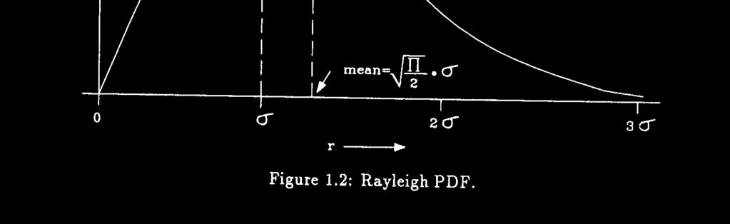
39 Rayleigh Fading PDF Rayleigh Fading PDF and CDF

 r r - s pr ( ) = e ; for r³ 0 s When there is a dominant stationary t At")
40 Rayleigh Fading PDF Ricean Fading 1 Rayleigh fading, when there is No dominant stationary signal component (i.e., Non LoS scenario) r r - s pr ( ) = e ; for r³ 0 s When there is a dominant stationary signal component At the output of an envelope detector - adding a DC component at the random multi-path ( r + a ) ar s 0 ç r - æ ö pr ( ) = e Iç ; for ( a³ 0, r³ 0) s çès ø
41 Ricean Fading a - pea amplitude of the dominant signal I 0 (.) - modified Bessel function of the first ind and zero order, (available in Matlab with, besseli) Described in terms of a Ricean factor, K a = s a K ( db) = 10log ( db) s Ricean PDF
42 Rayleigh/Ricean Schematic Rayleigh(a) and Ricean(b) Schematic


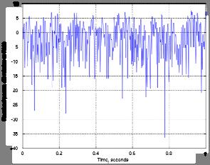
43 Rayleigh Fading One second of Rayleigh fading with a maximum Doppler shift of 10 Hz. One second of Rayleigh fading with a maximum Doppler shift of 100 Hz. Fading in Brief
 must be removed before decision maing (the case is illustrated below for a binary signal, where symbol =")
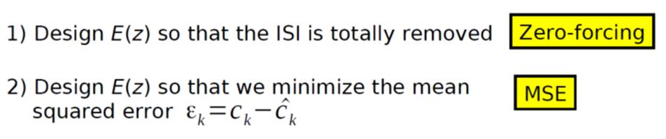
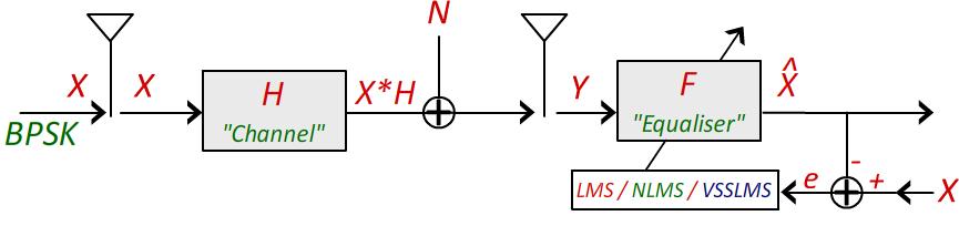
44 Channel Equalization Equalizer The goal of equalizers is to eliminate inter symbol interference (ISI) and the additive noise as much as possible. The inter symbol interference of received symbols (bits) must be removed before decision maing (the case is illustrated below for a binary signal, where symbol = bit): Equalizer
45 Equalizer Equalizer
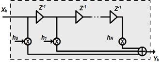
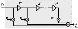
46 Equalization Techniques or Structures Three Basic Equalization Structures Linear Transversal Filter Simple implementation using Tap Delay Line or FIR filters FIR filter has guaranteed stability (although adaptive algorithm which determines coefficients may still be unstable) Decision Feedbac Equalizer Extra step in subtracting estimated residual error from signal Maximal Lielihood Sequence Estimator (Viterbi) Optimal performance High complexity and implementation problem (not heavily used) Linear Transversal Equalizer This is simply a linear filter with adjustable parameters The parameters are adjusted on the basis of the measurement of the channel characteristics A common choice for implementation is the transversal filter (Tap Delay Line) or the FIR filter with adjustable tap coefficient Fig. 3.6 Total number of taps = N+1 Total delay = N
47 Linear Equalizers Linear Equalizer:
48 LMS: Initialize:, Repeat for X W * y e X X W W e End W 1 y 0 1 max Mapping
49 LMS Results: H=[0.9], SNR=18 db, µ = 0.08, α=0.85, γ=0.1, E-taps= LMS Results: H=[0.9], SNR=18 db, µ = 0.08, α=0.85, γ=0.1, E-taps=
![LMS Results: H=[0.9], SNR=18 db, µ = 0.08, α=0.85, γ=0.](/docs-images/87/96919774/images/50-3.jpg "1, E-taps= Least Squares Channel Estimation training data")
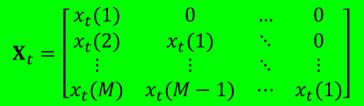
50 LMS Results: H=[0.9], SNR=18 db, µ = 0.08, α=0.85, γ=0.1, E-taps= Least Squares Channel Estimation training data Tx Rx

51 Least Squares Channel Estimation training Tx data Rx Least Squares Channel Estimation Representation 1: training Tx data Rx Representation :

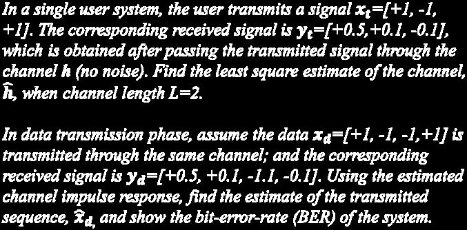
52 Summary Channel Estimation: training data Tx Rx Channel Equalization: Example

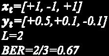
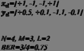
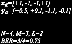
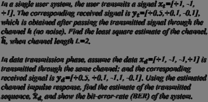
53 Example Moore Penrose pseudoinverse Example pseudoinverse BER=0/4=0

54 Decision feedbac equalization (DFE): Performances better than LE, due to ISI cancellation of tails of previously received symbols. Decision feedbac equalization (DFE):
55 Wiener solution R = correlation matrix (M x M) of received (sampled) signal values p = vector (of length M) indicating cross-correlation between received signal values and estimate of received symbol copt = vector (of length M) consisting of the optimal equalizer coefficient values LMS converges to Decision feedbac equalization (DFE):

56 Basic Idea: Linear, Zero-Forcing Linear, Zero-Forcing
 n, n where he ( t) ht ( t)* hc ( t)* hr ( t), n ( t) n( t ) * h ( t) e R Nyquist condition for zero ISI A pulse will produce zero ISI at sampling instants if it satisfies h e 1, ( nt) 0, n 0")
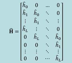
57 ISI Baseband Communication System Model where h ( t) Impulse response of the transmitte r T h ( t) Impulse response of the channel C h ( t) Impulse response of the receiver R y( T) h 0 a anhe ( T nt) ne ( T) n, n where he ( t) ht ( t)* hc ( t)* hr ( t), n ( t) n( t ) * h ( t) e R Nyquist condition for zero ISI A pulse will produce zero ISI at sampling instants if it satisfies h e 1, ( nt) 0, n 0 n 0 provided that its Fourier Transform satisfy n n He f T T
 function will satisfy this but we see a pulse shape that Has a more gradual transition in the frequency domain Is more robust to timing errors Yet still satisfies Nyquist s condition for zero ISI")
58 A sinc(.) function will satisfy this but we see a pulse shape that Has a more gradual transition in the frequency domain Is more robust to timing errors Yet still satisfies Nyquist s condition for zero ISI Consider a pulse shape that satisfies: In this case, pulse touch and almost begin to overlap There are many H e (f) for which H(f) = T B T or B T 1 1 Raised Cosine Pulse W f W f W W W W W W f W W f f H 0,, ) ( 4 cos 1, ) ( ) ) (4( 1 ] ) ( cos[ ) ( ) ( t W W t W W t W Sa W t h e Frequency domain Time domain where W= absolute bandwidth, W 0 =R s /=1/T is the minimum theoretical bandwidth and W-W 0 = excess bandwidth, r = (W-W 0 )/W0 is the rolloff factor and is in the range 0 r 1.
 R s The DSB bandwidth can be written as: W ( 1 r ) DSB R s Example 3.")
59 If we denote A RC rolloff pulse shape is defined in this case by the rolloff factor f W W 0 r f 0 W 0 where f o is the 6 db bandwidth of the pulse f1 and f are related to the pulse bandwidth B (or W) as shown in the figure: Solving for bandwidth in terms of the roll off factor and symbol rate, we have: 1 W (1 r ) R s The DSB bandwidth can be written as: W ( 1 r ) DSB R s Example 3.3: Find the minimum bandwidth for the baseband transmission of a 4 level PAM having a R=400bits/sec and r=1.
60 Root RC rolloff Pulse Shaping We saw earlier that the noise is minimized at the receiver by using a matched filter If the transmit filter is H(f), then the receive filter should be H*(f) The combination of transmit and receive filters must satisfy Nyquist s first method for zero ISI H ( f ) H( f ) H e * ( f ) H( f ) H ( f ) e Transmit filter with the above response is called the root raised cosine-rolloff filter Root RC rolloff pulse shapes are used in many applications such as IS- 54 and IS R R C P ulse S hape R C P ulse S hape (E xcess B W = 0.5)
61 Eye Patterns An eye pattern is obtained by superimposing the actual waveforms for large numbers of transmitted or received symbols Perfect eye pattern for noise-free, bandwidth-limited transmission of an alphabet of two digital waveforms encoding a binary signal (1 s and 0 s) Actual eye patterns are used to estimate the bit error rate and the signal to- noise ratio Concept of the eye pattern
62 EYE DIAGRAM Time (sec) 1.5 EYE DIAGRAM WITH NOISE (Variance =0.1) Time (sec)
63 3 EYE DIAGRAM WITH NOISE (Variance =0.5) Time (sec) 3.4 Equalization Nyquist filtering and pulse shaping schemes assumes that the channel is precisely nown and its characteristics do not change with time However, in practice we encounter channels whose frequency response are either unnown or change with time For example, each time we dial a telephone number, the communication channel will be different because the communication route will be different However, when we mae a connection, the channel becomes time-invariant The characteristics of such channels are not nown a priori Examples of time-varying channels are radio channels These channels are characterized by time-varying frequency response characteristics
64 To compensate for channel induced ISI we use a process nown as Equalization: a technique of correcting the frequency response of the channel The filter used to perform such a process is called an equalizer Since H R (f) is matched to H T (f), we usually worry about H C (f) The goal is to pic the frequency response H EQ (f) of the equalizer such that 1 jc ( f ) H c ( f ) H EQ ( f ) 1 H EQ ( f ) e where H C ( f ) 1 H and the phase characteristics EQ( f ) EQ ( f ) C ( f ) H ( f ) C Problems with Equalization It can be difficult to determine the inverse of the channel response If the channel response is zero at any frequency, then the inverse is not defined at that frequency The receiver generally does not now what the channel response is. Channel changes in real time so equalization must be adaptive The equalizer can have an infinite impulse response even if the channel has a finite impulse response The impulse response of the equalizer must usually be truncated
65 N is chosen sufficiently large so that equalizer spans length of the ISI. Normally the ISI is assumed to be limited to a finite number of samples The output y of the Tap Delay Line equalizer in response to the input sequence {x } is N y c x, N,... N n n N n where c n is the weight of the n th tap Ideally, we would lie the equalizer to eliminate ISI resulting in y 1, 0, 0 0 But this cannot be achieved in practice. However, the tap gains can be chosen such that y 1, 0 0, 1,,... N There are two types of such equalizer (i.e., linear equalizers) Preset Equalizer: Transmits a training sequence that is compared at the receiver with a locally generated sequence Requires an initial training sequence Differences between sequences are used to update the coefficient c n Time varying channel can change the sequence, since the coefficients are fixed Adaptive Equalizer: Equalizer adjust itself periodically during transmission of data
66 The tap weights constitute the adaptive filter coefficient The two techniques can be combined into a robust equalizer In this case, there are two modes of operation: Training Mode For the training mode, a nown sequence is transmitted and a synchronized version is generated at the receiver Decision-directed mode When training mode is complete, the adaptive algorithm is switched on The tap weights are then adjusted with info from training mode The impulse response of the transversal filter is h eq ( t ) H n N eq ( N f c ( t ) n N n N n ) c n e j fn If x(t) is the signal pulse corresponding to X ( f ) H ( f ) H ( f ) H ( f T C R ) then the equalized output signal is N y ( t ) c x ( t n ) Nyquist zero ISI condition implies that n N n y N 1, y( T ) cn x( T n ) n N 0, 0 1,,..., N
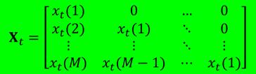
67 Since there are N+1 equalizer coefficients, we may express in matrix form as: y=xc where: x = (N+1) x(n+1) matrix with elements x(t - n) c = (N+1) column coefficient vector y = (N+1) column vector Since this design forces the ISI to be zero at sampling instants t = T, the equalizer is called zero-forcing equalizer (ZFE) Thus we obtain a set of (N+1) linear equations for the ZFE In Figure 3.6 is chosen as high as T = T Symbol-spaced equalizer; < T Fractional-spaced equalizer Example 3.5: (Page 155) 1 Received Pulse
68 Decision Feedbac Equalizer A decision-feedbac equalizer (DFE) is a nonlinear equalizer that employs previous decisions to eliminate the ISI caused by previously detected symbol It consists of a feedforward section a feedbac section and a detector connected together as shown The filters are usually fractionally spaced FIR with adjustable tap coefficients The detector is a symbol-by-symbol detector
Wireless Channel Modeling (Modeling, Simulation, and Mitigation)
") Wireless Channel Modeling (Modeling, Simulation, and Mitigation) Dr. Syed Junaid Nawaz Assistant Proessor Department o Electrical Engineering COMSATS Institute o Inormation Technology Islamabad, Paistan.
Wireless Channel Modeling (Modeling, Simulation, and Mitigation) Dr. Syed Junaid Nawaz Assistant Proessor Department o Electrical Engineering COMSATS Institute o Inormation Technology Islamabad, Paistan.
Digital Communications over Fading Channel s
 over Fading Channel s Instructor: Prof. Dr. Noor M Khan Department of Electronic Engineering, Muhammad Ali Jinnah University, Islamabad Campus, Islamabad, PAKISTAN Ph: +9 (51) 111-878787, Ext. 19 (Office),
Muhammad Ali Jinnah University, Islamabad Campus, Pakistan. Fading Channel. Base Station
 Fading Lecturer: Assoc. Prof. Dr. Noor M Khan Department of Electronic Engineering, Muhammad Ali Jinnah University, Islamabad Campus, Islamabad, PAKISTAN Ph: +9 (51) 111-878787, Ext. 19 (Office), 186 (ARWiC
Multi-Path Fading Channel
 Instructor: Prof. Dr. Noor M. Khan Department of Electronic Engineering, Muhammad Ali Jinnah University, Islamabad Campus, Islamabad, PAKISTAN Ph: +9 (51) 111-878787, Ext. 19 (Office), 186 (Lab) Fax: +9
Channel. Muhammad Ali Jinnah University, Islamabad Campus, Pakistan. Multi-Path Fading. Dr. Noor M Khan EE, MAJU
 Instructor: Prof. Dr. Noor M. Khan Department of Electronic Engineering, Muhammad Ali Jinnah University, Islamabad Campus, Islamabad, PAKISTAN Ph: +9 (51) 111-878787, Ext. 19 (Office), 186 (Lab) Fax: +9
Wireless Channel Propagation Model Small-scale Fading
 Wireless Channel Propagation Model Small-scale Fading Basic Questions T x What will happen if the transmitter - changes transmit power? - changes frequency? - operates at higher speed? Transmit power,
The Radio Channel. COS 463: Wireless Networks Lecture 14 Kyle Jamieson. [Parts adapted from I. Darwazeh, A. Goldsmith, T. Rappaport, P.
 The Radio Channel COS 463: Wireless Networks Lecture 14 Kyle Jamieson [Parts adapted from I. Darwazeh, A. Goldsmith, T. Rappaport, P. Steenkiste] Motivation The radio channel is what limits most radio
Mobile Radio Propagation Channel Models
 Wireless Information Transmission System Lab. Mobile Radio Propagation Channel Models Institute of Communications Engineering National Sun Yat-sen University Table of Contents Introduction Propagation
EENG473 Mobile Communications Module 3 : Week # (12) Mobile Radio Propagation: Small-Scale Path Loss
 Mobile Radio Propagation: Small-Scale Path Loss") EENG473 Mobile Communications Module 3 : Week # (12) Mobile Radio Propagation: Small-Scale Path Loss Introduction Small-scale fading is used to describe the rapid fluctuation of the amplitude of a radio
EENG473 Mobile Communications Module 3 : Week # (12) Mobile Radio Propagation: Small-Scale Path Loss Introduction Small-scale fading is used to describe the rapid fluctuation of the amplitude of a radio
WIRELESS COMMUNICATION TECHNOLOGIES (16:332:546) LECTURE 5 SMALL SCALE FADING
 LECTURE 5 SMALL SCALE FADING") WIRELESS COMMUNICATION TECHNOLOGIES (16:332:546) LECTURE 5 SMALL SCALE FADING Instructor: Dr. Narayan Mandayam Slides: SabarishVivek Sarathy A QUICK RECAP Why is there poor signal reception in urban clutters?
WIRELESS COMMUNICATION TECHNOLOGIES (16:332:546) LECTURE 5 SMALL SCALE FADING Instructor: Dr. Narayan Mandayam Slides: SabarishVivek Sarathy A QUICK RECAP Why is there poor signal reception in urban clutters?
ECE 476/ECE 501C/CS Wireless Communication Systems Winter Lecture 6: Fading
 ECE 476/ECE 501C/CS 513 - Wireless Communication Systems Winter 2003 Lecture 6: Fading Last lecture: Large scale propagation properties of wireless systems - slowly varying properties that depend primarily
ECE 476/ECE 501C/CS Wireless Communication Systems Winter Lecture 6: Fading
 ECE 476/ECE 501C/CS 513 - Wireless Communication Systems Winter 2005 Lecture 6: Fading Last lecture: Large scale propagation properties of wireless systems - slowly varying properties that depend primarily
ECE 476/ECE 501C/CS Wireless Communication Systems Winter Lecture 6: Fading
 ECE 476/ECE 501C/CS 513 - Wireless Communication Systems Winter 2004 Lecture 6: Fading Last lecture: Large scale propagation properties of wireless systems - slowly varying properties that depend primarily
Mobile Radio Propagation: Small-Scale Fading and Multi-path
 Mobile Radio Propagation: Small-Scale Fading and Multi-path 1 EE/TE 4365, UT Dallas 2 Small-scale Fading Small-scale fading, or simply fading describes the rapid fluctuation of the amplitude of a radio
Small-Scale Fading I PROF. MICHAEL TSAI 2011/10/27
 Small-Scale Fading I PROF. MICHAEL TSAI 011/10/7 Multipath Propagation RX just sums up all Multi Path Component (MPC). Multipath Channel Impulse Response An example of the time-varying discrete-time impulse
Chapter 2 Channel Equalization
 Chapter 2 Channel Equalization 2.1 Introduction In wireless communication systems signal experiences distortion due to fading [17]. As signal propagates, it follows multiple paths between transmitter and
EC 551 Telecommunication System Engineering. Mohamed Khedr
 EC 551 Telecommunication System Engineering Mohamed Khedr http://webmail.aast.edu/~khedr 1 Mohamed Khedr., 2008 Syllabus Tentatively Week 1 Week 2 Week 3 Week 4 Week 5 Week 6 Week 7 Week 8 Week 9 Week
Wireless Communication: Concepts, Techniques, and Models. Hongwei Zhang
 Wireless Communication: Concepts, Techniques, and Models Hongwei Zhang http://www.cs.wayne.edu/~hzhang Outline Digital communication over radio channels Channel capacity MIMO: diversity and parallel channels
CALIFORNIA STATE UNIVERSITY, NORTHRIDGE FADING CHANNEL CHARACTERIZATION AND MODELING
 CALIFORNIA STATE UNIVERSITY, NORTHRIDGE FADING CHANNEL CHARACTERIZATION AND MODELING A graduate project submitted in partial fulfillment of the requirements For the degree of Master of Science in Electrical
CHAPTER 2 WIRELESS CHANNEL
 CHAPTER 2 WIRELESS CHANNEL 2.1 INTRODUCTION In mobile radio channel there is certain fundamental limitation on the performance of wireless communication system. There are many obstructions between transmitter
Revision of Wireless Channel
 Revision of Wireless Channel Quick recap system block diagram CODEC MODEM Wireless Channel Previous three lectures looked into wireless mobile channels To understand mobile communication technologies,
Text Book. References. Andrea Goldsmith, Wireless Communications, Cambridge University Press Wireless Communications
 Ammar Abu-Hudrouss Islamic University Gaza ١ Course Syllabus Text Boo Andrea Goldsmith,, Cambridge University Press 005. References 1. Rappaport, : Principles and Practice, Prentice Hall nd Ed. D. N. C.
Channel Models. Spring 2017 ELE 492 FUNDAMENTALS OF WIRELESS COMMUNICATIONS 1
 Channel Models Spring 2017 ELE 492 FUNDAMENTALS OF WIRELESS COMMUNICATIONS 1 Narrowband Channel Models Statistical Approach: Impulse response modeling: A narrowband channel can be represented by an impulse
UNIK4230: Mobile Communications Spring 2013
 UNIK4230: Mobile Communications Spring 2013 Abul Kaosher abul.kaosher@nsn.com Mobile: 99 27 10 19 1 UNIK4230: Mobile Communications Propagation characteristis of wireless channel Date: 07.02.2013 2 UNIK4230:
Narrow- and wideband channels
 RADIO SYSTEMS ETIN15 Lecture no: 3 Narrow- and wideband channels Ove Edfors, Department of Electrical and Information technology Ove.Edfors@eit.lth.se 2012-03-19 Ove Edfors - ETIN15 1 Contents Short review
EE5713 : Advanced Digital Communications
 EE573 : Advanced Digital Communications Week 4, 5: Inter Symbol Interference (ISI) Nyquist Criteria for ISI Pulse Shaping and Raised-Cosine Filter Eye Pattern Error Performance Degradation (On Board) Demodulation
Fundamentals of Digital Communication
 Fundamentals of Digital Communication Network Infrastructures A.A. 2017/18 Digital communication system Analog Digital Input Signal Analog/ Digital Low Pass Filter Sampler Quantizer Source Encoder Channel
Revision of Lecture One
 Revision of Lecture One System blocks and basic concepts Multiple access, MIMO, space-time Transceiver Wireless Channel Signal/System: Bandpass (Passband) Baseband Baseband complex envelope Linear system:
Revision of Lecture One
 Revision of Lecture One System block Transceiver Wireless Channel Signal / System: Bandpass (Passband) Baseband Baseband complex envelope Linear system: complex (baseband) channel impulse response Channel:
Simulation of Outdoor Radio Channel
 Simulation of Outdoor Radio Channel Peter Brída, Ján Dúha Department of Telecommunication, University of Žilina Univerzitná 815/1, 010 6 Žilina Email: brida@fel.utc.sk, duha@fel.utc.sk Abstract Wireless
Wireless Physical Layer Concepts: Part II
 Wireless Physical Layer Concepts: Part II Raj Jain Professor of CSE Washington University in Saint Louis Saint Louis, MO 63130 Jain@cse.wustl.edu Audio/Video recordings of this lecture are available at:
Lecture 1 Wireless Channel Models
 MIMO Communication Systems Lecture 1 Wireless Channel Models Prof. Chun-Hung Liu Dept. of Electrical and Computer Engineering National Chiao Tung University Spring 2017 2017/3/2 Lecture 1: Wireless Channel
EE3723 : Digital Communications
 EE3723 : Digital Communications Week 11, 12: Inter Symbol Interference (ISI) Nyquist Criteria for ISI Pulse Shaping and Raised-Cosine Filter Eye Pattern Equalization (On Board) 01-Jun-15 Muhammad Ali Jinnah
Chapter 3. Mobile Radio Propagation
 Chapter 3 Mobile Radio Propagation Based on the slides of Dr. Dharma P. Agrawal, University of Cincinnati and Dr. Andrea Goldsmith, Stanford University Propagation Mechanisms Outline Radio Propagation
WIRELESS COMMUNICATIONS PRELIMINARIES
 WIRELESS COMMUNICATIONS Preliminaries Radio Environment Modulation Performance PRELIMINARIES db s and dbm s Frequency/Time Relationship Bandwidth, Symbol Rate, and Bit Rate 1 DECIBELS Relative signal strengths
Antennas and Propagation. Chapter 6a: Propagation Definitions, Path-based Modeling
 Antennas and Propagation a: Propagation Definitions, Path-based Modeling Introduction Propagation How signals from antennas interact with environment Goal: model channel connecting TX and RX Antennas and
UNIVERSITY OF SOUTHAMPTON
 UNIVERSITY OF SOUTHAMPTON ELEC6014W1 SEMESTER II EXAMINATIONS 2007/08 RADIO COMMUNICATION NETWORKS AND SYSTEMS Duration: 120 mins Answer THREE questions out of FIVE. University approved calculators may
Narrow- and wideband channels
 RADIO SYSTEMS ETIN15 Lecture no: 3 Narrow- and wideband channels Ove Edfors, Department of Electrical and Information technology Ove.Edfors@eit.lth.se 27 March 2017 1 Contents Short review NARROW-BAND
9.4 Temporal Channel Models
 ECEn 665: Antennas and Propagation for Wireless Communications 127 9.4 Temporal Channel Models The Rayleigh and Ricean fading models provide a statistical model for the variation of the power received
Wireless Communication Fundamentals Feb. 8, 2005
 Wireless Communication Fundamentals Feb. 8, 005 Dr. Chengzhi Li 1 Suggested Reading Chapter Wireless Communications by T. S. Rappaport, 001 (version ) Rayleigh Fading Channels in Mobile Digital Communication
Part 4. Communications over Wireless Channels
 Part 4. Communications over Wireless Channels p. 1 Wireless Channels Performance of a wireless communication system is basically limited by the wireless channel wired channel: stationary and predicable
Session2 Antennas and Propagation
 Wireless Communication Presented by Dr. Mahmoud Daneshvar Session2 Antennas and Propagation 1. Introduction Types of Anttenas Free space Propagation 2. Propagation modes 3. Transmission Problems 4. Fading
Mobile Radio Propagation Channel Models
 Wireless Information Transmission System Lab. Mobile Radio Propagation Channel Models Institute of Communications Engineering National Sun Yat-sen University Table of Contents Introduction Propagation
IEEE Working Group on Mobile Broadband Wireless Access <http://grouper.ieee.org/groups/802/mbwa>
 2003-01-10 IEEE C802.20-03/09 Project Title IEEE 802.20 Working Group on Mobile Broadband Wireless Access Channel Modeling Suitable for MBWA Date Submitted Source(s)
CHAPTER 4 PERFORMANCE ANALYSIS OF THE ALAMOUTI STBC BASED DS-CDMA SYSTEM
 89 CHAPTER 4 PERFORMANCE ANALYSIS OF THE ALAMOUTI STBC BASED DS-CDMA SYSTEM 4.1 INTRODUCTION This chapter investigates a technique, which uses antenna diversity to achieve full transmit diversity, using
NETW 701: Wireless Communications. Lecture 5. Small Scale Fading
 NETW 701: Wireless Communications Lecture 5 Small Scale Fading Small Scale Fading Most mobile communication systems are used in and around center of population. The transmitting antenna or Base Station
Empirical Path Loss Models
 Empirical Path Loss Models 1 Free space and direct plus reflected path loss 2 Hata model 3 Lee model 4 Other models 5 Examples Levis, Johnson, Teixeira (ESL/OSU) Radiowave Propagation August 17, 2018 1
Written Exam Channel Modeling for Wireless Communications - ETIN10
 Written Exam Channel Modeling for Wireless Communications - ETIN10 Department of Electrical and Information Technology Lund University 2017-03-13 2.00 PM - 7.00 PM A minimum of 30 out of 60 points are
Lab 3.0. Pulse Shaping and Rayleigh Channel. Faculty of Information Engineering & Technology. The Communications Department
 Faculty of Information Engineering & Technology The Communications Department Course: Advanced Communication Lab [COMM 1005] Lab 3.0 Pulse Shaping and Rayleigh Channel 1 TABLE OF CONTENTS 2 Summary...
Wideband Channel Characterization. Spring 2017 ELE 492 FUNDAMENTALS OF WIRELESS COMMUNICATIONS 1
 Wideband Channel Characterization Spring 2017 ELE 492 FUNDAMENTALS OF WIRELESS COMMUNICATIONS 1 Wideband Systems - ISI Previous chapter considered CW (carrier-only) or narrow-band signals which do NOT
UWB Channel Modeling
 Channel Modeling ETIN10 Lecture no: 9 UWB Channel Modeling Fredrik Tufvesson & Johan Kåredal, Department of Electrical and Information Technology fredrik.tufvesson@eit.lth.se 2011-02-21 Fredrik Tufvesson
Channel Modelling ETIM10. Channel models
 Channel Modelling ETIM10 Lecture no: 6 Channel models Fredrik Tufvesson Department of Electrical and Information Technology Lund University, Sweden Fredrik.Tufvesson@eit.lth.se 2012-02-03 Fredrik Tufvesson
Channel Modeling ETI 085
 Channel Modeling ETI 085 Overview Lecture no: 9 What is Ultra-Wideband (UWB)? Why do we need UWB channel models? UWB Channel Modeling UWB channel modeling Standardized UWB channel models Fredrik Tufvesson
Department of Electronics and Communication Engineering 1
 UNIT I SAMPLING AND QUANTIZATION Pulse Modulation 1. Explain in detail the generation of PWM and PPM signals (16) (M/J 2011) 2. Explain in detail the concept of PWM and PAM (16) (N/D 2012) 3. What is the
LECTURE 3. Radio Propagation
 LECTURE 3 Radio Propagation 2 Simplified model of a digital communication system Source Source Encoder Channel Encoder Modulator Radio Channel Destination Source Decoder Channel Decoder Demod -ulator Components
RECOMMENDATION ITU-R P The prediction of the time and the spatial profile for broadband land mobile services using UHF and SHF bands
 Rec. ITU-R P.1816 1 RECOMMENDATION ITU-R P.1816 The prediction of the time and the spatial profile for broadband land mobile services using UHF and SHF bands (Question ITU-R 211/3) (2007) Scope The purpose
Application Note 37. Emulating RF Channel Characteristics
 Application Note 37 Emulating RF Channel Characteristics Wireless communication is one of the most demanding applications for the telecommunications equipment designer. Typical signals at the receiver
Wireless Networked Systems. Lec #1b: PHY Basics
 Wireless Networked Systems CS 795/895 - Spring 2013 Lec #1b: PHY Basics Tamer Nadeem Dept. of Computer Science Wireless Communication Page 2 Spring 2013 CS 795/895 - Wireless Networked Systems Radio Signal
Elham Torabi Supervisor: Dr. Robert Schober
 Low-Rate Ultra-Wideband Low-Power for Wireless Personal Communication Area Networks Channel Models and Signaling Schemes Department of Electrical & Computer Engineering The University of British Columbia
EITN85, FREDRIK TUFVESSON ELECTRICAL AND INFORMATION TECHNOLOGY
 Wireless Communication Channels Lecture 6: Channel Models EITN85, FREDRIK TUFVESSON ELECTRICAL AND INFORMATION TECHNOLOGY Content Modelling methods Okumura-Hata path loss model COST 231 model Indoor models
Problem Sheet 1 Probability, random processes, and noise
 Problem Sheet 1 Probability, random processes, and noise 1. If F X (x) is the distribution function of a random variable X and x 1 x 2, show that F X (x 1 ) F X (x 2 ). 2. Use the definition of the cumulative
Lecture 7/8: UWB Channel. Kommunikations
 Lecture 7/8: UWB Channel Kommunikations Technik UWB Propagation Channel Radio Propagation Channel Model is important for Link level simulation (bit error ratios, block error ratios) Coverage evaluation
EITN85, FREDRIK TUFVESSON, JOHAN KÅREDAL ELECTRICAL AND INFORMATION TECHNOLOGY. Why do we need UWB channel models?
 Wireless Communication Channels Lecture 9:UWB Channel Modeling EITN85, FREDRIK TUFVESSON, JOHAN KÅREDAL ELECTRICAL AND INFORMATION TECHNOLOGY Overview What is Ultra-Wideband (UWB)? Why do we need UWB channel
Chapter 9. Digital Communication Through Band-Limited Channels. Muris Sarajlic
 Chapter 9 Digital Communication Through Band-Limited Channels Muris Sarajlic Band limited channels (9.1) Analysis in previous chapters considered the channel bandwidth to be unbounded All physical channels
Chapter 5 Small-Scale Fading and Multipath. School of Information Science and Engineering, SDU
 Chapter 5 Small-Scale Fading and Multipath School of Information Science and Engineering, SDU Outline Small-Scale Multipath Propagation Impulse Response Model of a Multipath Channel Small-Scale Multipath
Implementation of a MIMO Transceiver Using GNU Radio
 ECE 4901 Fall 2015 Implementation of a MIMO Transceiver Using GNU Radio Ethan Aebli (EE) Michael Williams (EE) Erica Wisniewski (CMPE/EE) The MITRE Corporation 202 Burlington Rd Bedford, MA 01730 Department
Propagation Characteristics of a Mobile Radio Channel for Rural, Suburban and Urban Environments
 Propagation Characteristics of a Mobile Radio Channel for Rural, Suburban and Urban Environments Mr. ANIL KUMAR KODURI, Mr. VSRK. SHARMA 2, Mr. M. KHALEEL ULLAH KHAN 3, STUDENT, M.TECH 2,3 ASSOCIATE PROFESSOR
Ultra Wideband Radio Propagation Measurement, Characterization and Modeling
 Ultra Wideband Radio Propagation Measurement, Characterization and Modeling Rachid Saadane rachid.saadane@gmail.com GSCM LRIT April 14, 2007 achid Saadane rachid.saadane@gmail.com ( GSCM Ultra Wideband
ECS455: Chapter 5 OFDM
 ECS455: Chapter 5 OFDM 1 Dr.Prapun Suksompong www.prapun.com Office Hours: Library (Rangsit) Mon 16:20-16:50 BKD 3601-7 Wed 9:20-11:20 OFDM Applications 802.11 Wi-Fi: a/g/n/ac versions DVB-T (Digital Video
Testing c2k Mobile Stations Using a Digitally Generated Faded Signal
 Testing c2k Mobile Stations Using a Digitally Generated Faded Signal Agenda Overview of Presentation Fading Overview Mitigation Test Methods Agenda Fading Presentation Fading Overview Mitigation Test Methods
Objectives. Presentation Outline. Digital Modulation Lecture 03
 Digital Modulation Lecture 03 Inter-Symbol Interference Power Spectral Density Richard Harris Objectives To be able to discuss Inter-Symbol Interference (ISI), its causes and possible remedies. To be able
Point-to-Point Communications
 Point-to-Point Communications Key Aspects of Communication Voice Mail Tones Alphabet Signals Air Paper Media Language English/Hindi English/Hindi Outline of Point-to-Point Communication 1. Signals basic
Massive MIMO: Signal Structure, Efficient Processing, and Open Problems I
 Massive MIMO: Signal Structure, Efficient Processing, and Open Problems I Saeid Haghighatshoar Communications and Information Theory Group (CommIT) Technische Universität Berlin CoSIP Winter Retreat Berlin,
Performance Evaluation Of Digital Modulation Techniques In Awgn Communication Channel
 Performance Evaluation Of Digital Modulation Techniques In Awgn Communication Channel Oyetunji S. A 1 and Akinninranye A. A 2 1 Federal University of Technology Akure, Nigeria 2 MTN Nigeria Abstract The
TEMPUS PROJECT JEP Wideband Analysis of the Propagation Channel in Mobile Broadband System
 Department of Electrical Engineering and Computer Science TEMPUS PROJECT JEP 743-94 Wideband Analysis of the Propagation Channel in Mobile Broadband System Krzysztof Jacek Kurek Final report Supervisor:
Radio channel modeling: from GSM to LTE
 Radio channel modeling: from GSM to LTE and beyond Alain Sibille Telecom ParisTech Comelec / RFM Outline Introduction: why do we need channel models? Basics Narrow band channels Wideband channels MIMO
Communication Theory
 Communication Theory Adnan Aziz Abstract We review the basic elements of communications systems, our goal being to motivate our study of filter implementation in VLSI. Specifically, we review some basic
Propagation Channels. Chapter Path Loss
 Chapter 9 Propagation Channels The transmit and receive antennas in the systems we have analyzed in earlier chapters have been in free space with no other objects present. In a practical communication
Statistical multipath channel models
 Statistical multipath channel models 1. ABSTRACT *) in this seminar we examine fading models for the constructive and destructive addition of different multipath component *) science deterministic channel
Antennas & Propagation. CSG 250 Fall 2007 Rajmohan Rajaraman
 Antennas & Propagation CSG 250 Fall 2007 Rajmohan Rajaraman Introduction An antenna is an electrical conductor or system of conductors o Transmission - radiates electromagnetic energy into space o Reception
Contents. Telecom Service Chae Y. Lee. Data Signal Transmission Transmission Impairments Channel Capacity
 Data Transmission Contents Data Signal Transmission Transmission Impairments Channel Capacity 2 Data/Signal/Transmission Data: entities that convey meaning or information Signal: electric or electromagnetic
Unit 5 - Week 4 - Multipath Fading Environment
 2/29/207 Introduction to ireless and Cellular Communications - - Unit 5 - eek 4 - Multipath Fading Environment X Courses Unit 5 - eek 4 - Multipath Fading Environment Course outline How to access the portal
Exam 3 is two weeks from today. Today s is the final lecture that will be included on the exam.
 ECE 5325/6325: Wireless Communication Systems Lecture Notes, Spring 2010 Lecture 19 Today: (1) Diversity Exam 3 is two weeks from today. Today s is the final lecture that will be included on the exam.
BER ANALYSIS OF WiMAX IN MULTIPATH FADING CHANNELS
 BER ANALYSIS OF WiMAX IN MULTIPATH FADING CHANNELS Navgeet Singh 1, Amita Soni 2 1 P.G. Scholar, Department of Electronics and Electrical Engineering, PEC University of Technology, Chandigarh, India 2
Design of a Radio channel Simulator for Aeronautical Communications
 Design of a Radio channel Simulator for Aeronautical Communications Item Type text; Proceedings Authors Montaquila, Roberto V.; Iudice, Ivan; Castrillo, Vittorio U. Publisher International Foundation for
Mobile Communications
 Mobile Communications Part IV- Propagation Characteristics Professor Z Ghassemlooy School of Computing, Engineering and Information Sciences University of Northumbria U.K. http://soe.unn.ac.uk/ocr Contents
MSIT 413: Wireless Technologies Week 3
 MSIT 413: Wireless Technologies Week 3 Michael L. Honig Department of EECS Northwestern University January 2016 Why Study Radio Propagation? To determine coverage Can we use the same channels? Must determine
Digital Modulation Schemes
 Digital Modulation Schemes 1. In binary data transmission DPSK is preferred to PSK because (a) a coherent carrier is not required to be generated at the receiver (b) for a given energy per bit, the probability
Performance Evaluation of different α value for OFDM System
 Performance Evaluation of different α value for OFDM System Dr. K.Elangovan Dept. of Computer Science & Engineering Bharathidasan University richirappalli Abstract: Orthogonal Frequency Division Multiplexing
1.1 Introduction to the book
 1 Introduction 1.1 Introduction to the book Recent advances in wireless communication systems have increased the throughput over wireless channels and networks. At the same time, the reliability of wireless
Lecture 3: Wireless Physical Layer: Modulation Techniques. Mythili Vutukuru CS 653 Spring 2014 Jan 13, Monday
 Lecture 3: Wireless Physical Layer: Modulation Techniques Mythili Vutukuru CS 653 Spring 2014 Jan 13, Monday Modulation We saw a simple example of amplitude modulation in the last lecture Modulation how
EXAMINATION FOR THE DEGREE OF B.E. Semester 1 June COMMUNICATIONS IV (ELEC ENG 4035)
") EXAMINATION FOR THE DEGREE OF B.E. Semester 1 June 2007 101902 COMMUNICATIONS IV (ELEC ENG 4035) Official Reading Time: Writing Time: Total Duration: 10 mins 120 mins 130 mins Instructions: This is a closed
EXAMINATION FOR THE DEGREE OF B.E. Semester 1 June 2007 101902 COMMUNICATIONS IV (ELEC ENG 4035) Official Reading Time: Writing Time: Total Duration: 10 mins 120 mins 130 mins Instructions: This is a closed
EC 551 Telecommunication System Engineering. Mohamed Khedr
 EC 551 Telecommunication System Engineering Mohamed Khedr http://webmail.aast.edu/~khedr 1 Mohamed Khedr., 2008 Syllabus Tentatively Week 1 Week 2 Week 3 Week 4 Week 5 Week 6 Week 7 Week 8 Week 9 Week
Chapter 3 Digital Transmission Fundamentals
 Chapter 3 Digital Transmission Fundamentals Characterization of Communication Channels Fundamental Limits in Digital Transmission CSE 323, Winter 200 Instructor: Foroohar Foroozan Chapter 3 Digital Transmission
Multipath Propagation Model for High Altitude Platform (HAP) Based on Circular Straight Cone Geometry
 Based on Circular Straight Cone Geometry") Multipath Propagation Model for High Altitude Platform (HAP) Based on Circular Straight Cone Geometry J. L. Cuevas-Ruíz ITESM-CEM México D.F., México jose.cuevas@itesm.mx A. Aragón-Zavala ITESM-Qro Querétaro
Multipath Propagation Model for High Altitude Platform (HAP) Based on Circular Straight Cone Geometry J. L. Cuevas-Ruíz ITESM-CEM México D.F., México jose.cuevas@itesm.mx A. Aragón-Zavala ITESM-Qro Querétaro
Chapter 3 Data Transmission COSC 3213 Summer 2003
 Chapter 3 Data Transmission COSC 3213 Summer 2003 Courtesy of Prof. Amir Asif Definitions 1. Recall that the lowest layer in OSI is the physical layer. The physical layer deals with the transfer of raw
Project: IEEE P Working Group for Wireless Personal Area Networks N
 Project: IEEE P82.15 Working Group for Wireless Personal Area Networks N (WPANs( WPANs) Title: [UWB Channel Model for Indoor Residential Environment] Date Submitted: [2 September, 24] Source: [Chia-Chin
Wireless Sensor Networks 4th Lecture
 Wireless Sensor Networks 4th Lecture 07.11.2006 Christian Schindelhauer schindel@informatik.uni-freiburg.de 1 Amplitude Representation Amplitude representation of a sinus curve s(t) = A sin(2π f t + ϕ)
Performance comparison between different channel models with channel estimation and adaptive equalization using Rayleigh fading channel.
 Performance comparison between different channel models with channel estimation and adaptive equalization using Rayleigh fading channel. A Thesis Submitted to the Department of Computer Science and Engineering
Antennas and Propagation
 Antennas and Propagation Chapter 5 Introduction An antenna is an electrical conductor or system of conductors Transmission - radiates electromagnetic energy into space Reception - collects electromagnetic