Satellite Communications
|
|
|
- Damian Sparks
- 5 years ago
- Views:
Transcription
 3 electronics (amplifiers, filters, modems, etc) and a lot of")
1 Signal processing elements Department of Electrical and Computer Science University of Liège Academic year Signal processing elements Example of an analog communication system Main components: 1 signal 2 transmitting channel (cable, radio) 3 electronics (amplifiers, filters, modems, etc) and a lot of engineering!
2 Signal processing elements Outline 1 Signal processing elements Signal information! Source coding (dealing with the information content) Modulation Multiplexing 2 Introduction to radio communications Radiowave propagation Examples of antennas 3 Noise Link budget Outline Signal processing elements Signal information! Source coding (dealing with the information content) Modulation Multiplexing 1 Signal processing elements Signal information! Source coding (dealing with the information content) Modulation Multiplexing 2 Introduction to radio communications Radiowave propagation Examples of antennas 3 Noise Link budget
 Modulation Multiplexing Main types of satellite different types of information Astronomical satellites: used for the observation of distant")
3 Signal processing elements Signal information! Source coding (dealing with the information content) Modulation Multiplexing Main types of satellite different types of information Astronomical satellites: used for the observation of distant planets, galaxies, and other outer space objects. Navigational satellites [GPS, Galileo]: they use radio time signals transmitted to enable mobile receivers on the ground to determine their exact location (positioning). Earth observation satellites: used for environmental monitoring, meteorology, map making. Miniaturized satellites: satellites of unusually low masses and small sizes. For example, for educational purposes (OUFTI-1). Communications satellites: stationed in space for the purpose of telecommunications. Modern communications satellites typically use geosynchronous orbits, or Low Earth orbits (LEO). Example: constellation of GPS satellites 6 planes with a 55 angle with the equator, spaced by 60 and with 4 satellites per plane (24 satellites in total) Located on high orbits (but sub-geostationary)/revolution in 12 hours Transmitting power of 20 to 50[W]


4 Galileo I Positioning system promoted by the European commission and the ESA. Galileo GPS Orbital period 20 hours 15 hours 10 hours Geostationary Earth Orbit COMPASS MEO satellites GLONASS 5 hours Radius of orbit Iridium 40 Mm 30 Mm 20 Mm 10 Mm Hubble Height above sea level 10 Mm 20 Mm 30 Mm miles miles mph ISS km/h km/h miles miles mph km/h Orbital speed Galileo II Orbital altitude: 23,222 [km] (MEO - Medium Earth Orbit) 3 orbital planes, 56 inclination, separated by 120 longitude Constellation of 30 satellites (with working 24 [3x8] satellites and 6 [3x2] spares)
. November 2017: 15 satellites fully operational, 3 for testing or not available.")
5 Deployment of Galileo First launches: 2 satellites in October 2011, 2 satellites in October These were test satellites. First Full Operational Capability satellite launched in November August 2014, two more satellites (but... injected on a wrong orbit). November 2017: 15 satellites fully operational, 3 for testing or not available. Types of data streams Types of data Control data Payload Measurements Remote sensing data Localization data Broadcasting Digital data Characteristics Must be very reliable Unicast communication for mobile ground station Accurate signals with constant monitoring High volume of downstream data Accurate time reference (synchronization) Digital television channels Voice + data (Internet) for remote areas Because the purposes of data sent are different, the mechanisms to transmit the data are designed according to the constraints. Simplified typography of data streams: control data payload (+ some unavoidable overhead)
6 Signal processing elements Main issues related to signals Signal information! Source coding (dealing with the information content) Modulation Multiplexing 1 Signal source handling (preparation of the signal, at the source, in the transmitter): filtering (remove what is useless for communications) analog digital (digitization) remove the redundancy in the signal: compression 2 Signal over the channel: signal shaping to make it suitable for transmission (coding, modulation, multiplexing, etc) signal power versus the noise signal (protect the signal against noise effects) Digitization I Signal processing elements Signal information! Source coding (dealing with the information content) Modulation Multiplexing
 Modulation Multiplexing Digitization = from analog to digital analog digital g(t) samples g[it ], with i = 0, 1, 2,.")

7 Digitization II Signal processing elements Signal information! Source coding (dealing with the information content) Modulation Multiplexing Digitization = from analog to digital analog digital g(t) samples g[it ], with i = 0, 1, 2,... and T = a time period signal over time sampling rate series of samples each sample is coded with n bits (quantization) in the end, we have a bitsream: Digitization III Signal processing elements Signal information! Source coding (dealing with the information content) Modulation Multiplexing Digitization in numbers: 1 f s : sampling frequency Let W be the highest frequency of the signal to be converted theoretical lower bound: f s > 2W practical rule (Nyquist criterion): f s > 2.2W 2 n: number of bits par sample (quantization) 3 bit rate = f s n signal band W f s n bit rate units Hz Hz sample/s b/sa. b/s audio [300 Hz, 3400 Hz 8000 sa./s 8 64 kb/s (telephone) 3400 Hz] audio (CD) [0 Hz, 20 khz] 20 khz 44.1 ksa./s kb/s
8 Signal processing elements Signal information! Source coding (dealing with the information content) Modulation Multiplexing Analog and digital signals: don t confuse information and its representation! Analog information signal Digital information signal Analog representation Analog representation Characterization of signals over the channel Analog signal bandwidth [Hz] Signal to Noise Ratio (S/N or SNR) Reasons for going digital: Digital signal bit rate [bit/s] Bit Error Rate (BER) bandwidth of the underlying channel [Hz] possibility to regenerate a digital signal better bandwidth usage Example (better bandwidth usage: from analog to digital television) analog PAL television channel: bandwidth of 8[MHz] digital television, PAL quality 5[Mb/s] With a 64-QAM modulation, whose spectral efficiency is 6 b/s per Hz. A bandwidth of 8[MHz] allows for 48[Mb/s]. Conclusion: thanks to digitization, there is room for 10 digital television channels instead of 1 analog television channel.


9 Software organization of a transmitter/receiver: the OSI reference model Consequence: encapsulation overhead OSI reference model vs Internet model (+ some corresponding Internet protocols)

10 Elements of a communication system I Figure: Block diagram of a communication channel for a single signal. Elements of a communication system II
11 Outline Signal processing elements Signal information! Source coding (dealing with the information content) Modulation Multiplexing 1 Signal processing elements Signal information! Source coding (dealing with the information content) Modulation Multiplexing 2 Introduction to radio communications Radiowave propagation Examples of antennas 3 Noise Link budget Signal processing elements Signal information! Source coding (dealing with the information content) Modulation Multiplexing Information theory and channel capacity: there is maximum bit rate (the sky is not the limit...)! I Theorem (Shannon-Hartley) The channel capacity C (conditions for the Bit Error Rate BER 0) is given by ( C [b/s] = W log S ) N (1) where W is the channel bandwidth in Hz S N the Signal to Noise ratio (in watts/watts, not in db).
12 Consequences of the capacity theorem Let R b be the bit rate [b/s] and E b the energy per bit [Joule/b], we have S = E b R b [Watt], and N = N 0 W (where N 0 is the noise spectral power density; N 0 = k B T as shown later). Therefore: ( C = W log E ) b R b (2) N 0 W The ratio R b W is defined as the spectral efficiency given in [b/s] per [Hz]. Consequences: the capacity is bounded (there is a maximal limit), related to 1 the E b N 0 ratio. We only have control over E b. 2 the spectral efficiency. for a fixed E b N 0 ratio and spectral efficiency, C can only be increased by increasing the bandwidth. But the bandwidth is a scarce resource. Impact of errors on the transmission: bit/packet error rate Assume a packet of size N and let P e be the probability error on one bit ( Bit Error Rate, BER). The probability for the packet to be correct is Therefore the packet error rate is For large packets and small P e, this becomes Example (1 P e ) N. (3) P P = 1 (1 P e ) N. (4) P P 1 (1 NP e ) = N P e. (5) With N = 10 5 bits and a bit error rate of P e = 10 7, P P We thus need to lower P e error detection/correction mechanisms
13 Forward Error Coding A simplistic example of Forward Error Coding (FEC) consists to transmit each data bit 3 times, known as a (3,1) repetition code. Received bits Interpreted as (error free) (error free) Other forward error codes Hamming code Reed Solomon code Turbo code,...
14 Outline Signal processing elements Signal information! Source coding (dealing with the information content) Modulation Multiplexing 1 Signal processing elements Signal information! Source coding (dealing with the information content) Modulation Multiplexing 2 Introduction to radio communications Radiowave propagation Examples of antennas 3 Noise Link budget Signal processing elements Modulation: principles Signal information! Source coding (dealing with the information content) Modulation Multiplexing Principle Modulation is all about using of a carrier cosine at frequency f c for transmitting information. The carrier is A c cos(2πf c t) Frequency modulation [FM] s(t) = A(t)cos(2πf (t)t + φ(t)) Amplitude Phase Amplitude modulation [AM] Phase modulation [PM]
15 Consequences of modulation frequency band is shifted towards the carrier frequency ( f c ) bandwidth modification, compared to that of the modulating signal m(t) Effects of Amplitude Modulation on the spectrum ( s(t) = A c m(t)cos(2πf c t) ) M(f ) W 0 +W (a) S(f ) f USB f c W f c LSB f c + W 0 (b) LSB f c W f c USB f f c + W Demodulation of an AM modulated signal: principles Received signal: s(t) = m(t)cos(2πf c t). Task: recover m(t). Principles of a synchronous demodulation. At the receiver: 1 acquire a local, synchronous, copy of the carrier f c build a local copy of cos(2πf c t) 2 multiply s(t) by cos(2πf c t): [cosa cosb = 1 2 cos(a b) cos(a + b)] s(t)cos(2πf c t) = m(t)cos 2 (2πf c t) (6) 3 filter out the 2f c components 1 2 m(t) = m(t)[ cos(2π(2f c)t)] (7) = 1 2 m(t) m(t)cos(2π(2f c)t)] (8)
 techniques I")
16 Demodulation of an AM modulated signal: interpretation in the spectral domain AM spectrum Spectrum of the carrier A c /2 A c /2 1/2 1/2 Mixer f c f f c f f f c c Spectrum of the mixed signal A c /2 A c /4 A c /4 2f c f W c W f c 2f c f Signal spectrum A c /2 W W f Basic digital modulation (coding) techniques I
17 Basic digital modulation (coding) techniques II Quadrature modulation It is possible to use both a cosine and a sine: s(t) = m 1 (t)cos(2πf c t) m 2 (t)sin(2πf c t) (9) m 1 (t)cos(2πf c t) cos(2πf c )t m 1 (t) m 2 (t) π 2 + s(t) sin(2πf c )t m 2 (t)sin(2πf c t)
18 Quadrature demodulation: principles s(t) = m 1 (t)cos(2πf c t) + m 2 (t)sin(2πf c t) is the modulated signal. We want to recover m 1 (t) and m 2 (t) Step 1: multiply by cos(2πf c t) [remember that cosa cosb = 1 2 cos(a b) cos(a + b) and that cosa sina = 1 2 sin(2a)] s(t) cos(2πf c t) = m 1 (t)cos 2 (2πf c t) + m 2 (t)sin(2πf c t)cos(2πf c t) = 1 2 m 1(t) m 1(t)cos(2π(2f c )t) m 2(t)sin(2π(2f c )t) Step 2: filter to keep the baseband signal 1 2 m 1(t) Steps 3 and 4: multiply by sin(2πf c t) and low-pass filter to get m 2 (t) Purposes of the quadrature modulation There are 2 possible uses/advantages for a quadrature modulation: 1 [Bandwidth savings by a factor of 2] Send two signals in the same bandwidth s(t) = m 1 (t)cos(2πf c t) + m 2 (t)sin(2πf c t) (10) Both m 1 (t)cos(2πf c t) and m 2 (t)sin(2πf c t) have exactly the same bandwidth, that is [f c W, f c + W ] where W denotes the original bandwidth of m 1 (t) and m 2 (t). 2 [Easier demodulation] A coherent demodulation of m(t)cos(2πf c t + φ c ) requires the perfect knowledge of f c and φ c at the receiver. However, it is sometimes difficult to synchronize the receiver. Therefore, s(t) = m(t)cos(2πf c t + φ c ) + m(t)sin(2πf c t + φ c ) (11) is sometimes used. At the receiver, m(t), the signal of interest can be obtained by m 2 (t)cos 2 (.) + m 2 (t)sin 2 (.) = m(t).
19 Outline Signal processing elements Signal information! Source coding (dealing with the information content) Modulation Multiplexing 1 Signal processing elements Signal information! Source coding (dealing with the information content) Modulation Multiplexing 2 Introduction to radio communications Radiowave propagation Examples of antennas 3 Noise Link budget Signal processing elements Multiplexing: combining several sources Mechanisms to share resources between users: Frequency Division Multiplexing (FDM) Time Division Multiplexing (TDM) Code Division Multiplexing (CDM) Space Division Multiplexing + combinations! Signal information! Source coding (dealing with the information content) Modulation Multiplexing
20 Frequency Division Multiplexing (FDM) X 1 (f ) f X 2 (f ) f 1 f 1 f 1 f f X 3 (f ) f 2 f 2 f 2 f f f 3 f 3 f 3 f Multiplexed signal Demultiplexing f 3 f 2 f 1 f 1 f 2 f 3 f Multiplexed signal f 3 f 2 f 1 f 1 f 2 f 3 f f 1 f 2 f 3 f 1 f 2 f 3 X 1 (f ) X 2 (f ) X 3 (f ) f f f
21 Time Division Multiplexing (TDM) Spread spectrum for Code Division Multiplexing Principle of spread spectrum: multiply a digital signal with a faster pseudo-random sequence (spreading step) Binary data waveform T b (one bit) t F B 0 B f Spreading sequence t F NB 0 NB f Spread sequence T c t F (N + 1)B 0 f (N + 1)B At the receiver, the same, synchronized, pseudo-random sequence is generated and used to despread the signal (despreading step)
 Code Physical channel Frequency Time User 1 User 2 Free channel")
22 Code Division Multiple Access Each user is given its own code (multiple codes can be used simultaneously) Code Physical channel Frequency Time User 1 User 2 Free channel Summary
23 Outline Signal processing elements Introduction to radio communications Radiowave propagation Examples of antennas 1 Signal processing elements Signal information! Source coding (dealing with the information content) Modulation Multiplexing 2 Introduction to radio communications Radiowave propagation Examples of antennas 3 Noise Link budget Signal processing elements Satellite link definition Introduction to radio communications Radiowave propagation Examples of antennas
: Radio-communications Sector (ITU-R) service regions organizes WARC (World Administrative Radio Conference) - worldwide allocation of")
24 Frequency bands But it is also common to designate the carrier frequency and bandwidth directly. Regulatory bodies International Telecommunications Union (ITU): Radio-communications Sector (ITU-R) service regions organizes WARC (World Administrative Radio Conference) - worldwide allocation of frequencies Regional body: European Conference of Postal and Telecommunications Administrations (CEPT)
![Excerpt of the allocation plan/radio spectrum (by the ITU) Frequency allocations [2] Radio-communications service Typical up/down link Terminology Fixed satellite service (FSS) 6/4[GHz] C band](/docs-images/87/96196734/images/25-0.jpg "8/7[GHz] X band 14/12.1[GHz] Ku band 30/20[GHz] Ka band 50/40[GHz] V band Mobile satellite service (MSS) 1.6/1.5[GHz] L band 30/20[GHz] Ka band Broadcasting satellite service (BSS) 2/2.")
25 Excerpt of the allocation plan/radio spectrum (by the ITU) Frequency allocations [2] Radio-communications service Typical up/down link Terminology Fixed satellite service (FSS) 6/4[GHz] C band 8/7[GHz] X band 14/12.1[GHz] Ku band 30/20[GHz] Ka band 50/40[GHz] V band Mobile satellite service (MSS) 1.6/1.5[GHz] L band 30/20[GHz] Ka band Broadcasting satellite service (BSS) 2/2.2[GHz] S band 12[GHz] Ku band 2.6/2.5[GHz] S band Note that frequencies for down links are usually lower than for up links: this is because the power loss increases with the frequency. The use of higher frequencies allows larger bandwidths, better tracking capability and minimizes ionospheric effects. But it also requires greater pointing accuracy
26 Frequency allocations [2] Radio-communications service Typical up/down link Terminology Fixed satellite service (FSS) 6/4[GHz] C band 8/7[GHz] X band 14/12.1[GHz] Ku band 30/20[GHz] Ka band 50/40[GHz] V band Mobile satellite service (MSS) 1.6/1.5[GHz] L band 30/20[GHz] Ka band Broadcasting satellite service (BSS) 2/2.2[GHz] S band 12[GHz] Ku band 2.6/2.5[GHz] S band Orbits Note that frequencies for down links are usually lower than for up links: this is because the power loss increases with the frequency. The use of higher frequencies allows larger bandwidths, better tracking capability and minimizes ionospheric effects. But it also requires greater pointing accuracy considerations: distance between user and satellite. delay (increases with the distance) attenuation of the signal (increases with the distance) relative position of the user/satellite pair
27 Signal processing elements Introduction to radio communications Radiowave propagation Examples of antennas Outline 1 Signal processing elements Signal information! Source coding (dealing with the information content) Modulation Multiplexing 2 Introduction to radio communications Radiowave propagation Examples of antennas 3 Noise Link budget Signal processing elements Introduction to radio communications Radiowave propagation Examples of antennas Radiowave propagation d P R P T Important issues: channel characteristics attenuation (distance) atmospheric effects wave polarization rain mitigation antenna design power budget (related to the Signal to Noise ratio)
28 Two main types of radiation pattern Reciprocity Theorem (Reciprocity for antennas) The electrical characteristics of an antenna such as gain, radiation pattern, impedance, bandwidth, resonant frequency and polarization, are the same whether the antenna is transmitting (T ) or receiving (R). Theorem (Strong reciprocity) If a voltage is applied to an antenna A and the current is measured at another antenna B, then an equal current (in both amplitude and phase) will appear at A if the same voltage is applied to B.
29 Inverse square law of radiation The power flux density (or power density) S, over the surface of a sphere of radius r a from the point P, is given by (Poynting vector) S a = P t 4πr 2 a [ W m 2 ] Effective Isotropic Radiated Power [EIRP] (12) Definition (EIRP) The Effective Isotropic Radiated Power (EIRP) of a transmitter is the power that the transmitter appears to have if the transmitter were an isotropic radiator (if the antenna radiated equally in all directions). From the receiver s point of view, where: P t = P T G T (13) P t is the power of a imaginary isotropic antenna. P T is the transmitter power and G T is its gain (in that direction). If the cable losses can be neglected, then EIRP = P T G T.
30 Effective area Definition (Effective area) The effective area of an antenna is the ratio of the available power to the power flux density (Poynting vector): A eff,r = P R S eff,r (14) Theorem The effective area of an antenna is related to its gain by the following formula λ 2 A eff,r = G R (15) 4π By reciprocity, all these results are equally valid for a transmitting antenna T. Friis s relationship d P R We have P T P R = S eff,r A eff,r ( PT G T = 4πd 2 ) A eff,r = ( PT G T 4πd 2 ) ( λ 2 ) 4π ( ) λ 2 G R = P T G T G R 4πd Free space path loss L FS = ( λ 4πd ) 2 ɛ = P T P R = Friis s relationship ( 4πd λ ) 2 1 G T G R
31 Decibel as a common power unit x 10log 10 (x)[db] (16) P [dbm] = 10log 10 P [mw] 1[mW] (17) x [W] 10log 10 (x)[dbw] 1[W] 0[dBW] 2[W] 3[dBW] 0,5[W] 3[dBW] 5[W] 7[dBW] 10 n [W] 10 n [dbw] Orders of magnitude in satellite communications: transmitter power: 100[W] 20[dB] received power: 100[pW] = [W] 100[dB] Free space losses
32 Are high frequencies less adequate? In [db], Friis s relationship becomes ɛ = logf [MHz] + 20logd [km] G T [db] G R [db] The attenuation (loss) increases with f. So?! Remember that So, A eff = G λ2 4π (18) ( ) 4πd 2 ( ) 1 4πd 2 λ 2 λ 2 ɛ = = (19) λ G T G R λ 4πA T 4πA R = λ2 d 2 = c2 d 2 A T A R f 2 (20) A T A R It all depends on the antenna gains! Are high frequencies less adequate? In [db], Friis s relationship becomes ɛ = logf [MHz] + 20logd [km] G T [db] G R [db] The attenuation (loss) increases with f. So?! Remember that So, A eff = G λ2 4π (18) ( ) 4πd 2 ( ) 1 4πd 2 λ 2 λ 2 ɛ = = (19) λ G T G R λ 4πA T 4πA R = λ2 d 2 = c2 d 2 A T A R f 2 (20) A T A R It all depends on the antenna gains!
![Practical case: VSAT in the Ku-band [1] Antenna gains: 48.93[dB] The free space path loss is, in [db], L FS = 32.5 + 20logf [MHz] + 20logd [km] = 205.](/docs-images/87/96196734/images/33-0.jpg "1[dB] The received power is, in [db], P R = P T + G T + G R L FS (21) = 10 + 48.93 + 48.93 205.1 = 97.24[dB] (22) In [W], the received power is P R = 10 97.24 10 = 1.")
33 Practical case: VSAT in the Ku-band [1] Antenna gains: 48.93[dB] The free space path loss is, in [db], L FS = logf [MHz] + 20logd [km] = 205.1[dB] The received power is, in [db], P R = P T + G T + G R L FS (21) = = 97.24[dB] (22) In [W], the received power is P R = = [W] = 189[pW] (23) Signal processing elements Introduction to radio communications Radiowave propagation Examples of antennas Outline 1 Signal processing elements Signal information! Source coding (dealing with the information content) Modulation Multiplexing 2 Introduction to radio communications Radiowave propagation Examples of antennas 3 Noise Link budget

34 Signal processing elements Terrestrial antennas Introduction to radio communications Radiowave propagation Examples of antennas Beamwidth and aperture


35 Ground station antenna Parabolic (dish) antenna Radiation pattern


36 Deployable antenna Horn antenna and waveguide feed

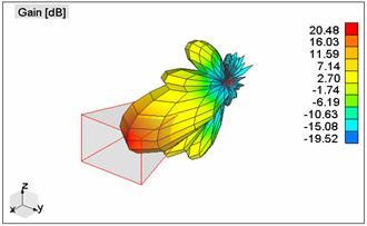
37 Yagi antenna Patch array antenna


38 Phased array antenna Radiowave propagation mechanisms + Doppler effect
![Earth atmosphere absorption Expressed in terms of the wavelength:λ[m] = c f = 3 108 [m/s] f [Hz] Attenuation due to](/docs-images/87/96196734/images/39-0.jpg "atmospheric gases Zenith attenuation due to atmospheric gases (source: ITU-R P.")
39 Earth atmosphere absorption Expressed in terms of the wavelength:λ[m] = c f = [m/s] f [Hz] Attenuation due to atmospheric gases Zenith attenuation due to atmospheric gases (source: ITU-R P.676-6) [O 2 and H 2 0 are the main contributors]
40 Rain attenuation Total path rain attenuation as a function of frequency and elevation angle. Cloud attenuation Location: Washington, DC, Link Availability: 99% Cloud attenuation as a function of frequency, for elevation angles from 5 to 30
41 Total attenuation The ITU recommends that all tropospheric contributions to signal attenuation are combined as follows: A T (p) = A G + (A R (p) + A c (p)) 2 + A s (p) (24) where: A T (p) is the total attenuation for a given probability A G (p) is the attenuation due to water vapor and oxygen A R (p) is the attenuation due to rain A c (p) is the attenuation due to clouds A s (p) is the attenuation due to scintillation (rapid fluctuations attributed to irregularities in the tropospheric refractive index) Service Level Agreement (SLA) Customers ask for a guaranteed level of quality: this leads to a Service Level Agreement (SLA) with the satellite operator. In engineering terms: introduction of power margins!
42 Signal processing elements Noise Link budget Outline 1 Signal processing elements Signal information! Source coding (dealing with the information content) Modulation Multiplexing 2 Introduction to radio communications Radiowave propagation Examples of antennas 3 Noise Link budget Signal processing elements Noise Link budget Noise Theorem (Nyquist s formula for a one-port noise generator) The available power from a thermal source in a bandwidth of W is where P N = k B T W (25) k B = 1, [J/K] is the constant of Boltzmann ( 198[dBm/K/Hz] = 228.6[dBW/K/Hz]), T is the equivalent noise temperature of the noise source W is the bandwidth of the system Thermal noise is one the main sources of noise in a satellite put electronics in the cold zone of a satellite
43 Noise in two-port circuits Definitions Noise Factor (F ): [provided by the manufacturer] F = ( SN ) in ( SN ) out > 1 (26) Noise Figure (NF): NF=10 log 10 F (27) Effective noise temperature T e (T 0 = 290[K]): Noise factor of a two-port cascade T e = T 0 (F 1) (28) (F 01 1)γ an1 (f ) F 01 (F 02 1)γ an1 (f ) F 02 γ an1 (f ) G 1 G 1 F 01 γ an1 (f ) G 2 Figure: Cascading two-port elements. For a two-port network with n stages, F 0 = F 01 + F 02 1 G 1 + F 03 1 G 1 G 2 + = F 01 + n i=2 F 0i 1 i 1 j=1 G j (29) Likewise, T e = T e1 + T e2 G 1 + T e3 G 1 G 2 + = T e1 + n i=2 T ei i 1 j=1 G j (30)
 and best noise figure (F 01 ) first.")
44 Receiver front end I Figure: Block diagram of a typical receiver. Receiver front end II Rule of thumb: highest gain (G 1 ) and best noise figure (F 01 ) first. Then F 0 = F 01 + F 02 1 G 1 + F 03 1 G 1 G 2 + F 01 + F 02 1 G 1 (31) T e = T e1 + T e2 G 1 + T e3 G 1 G 2 + T e1 + T e2 G 1 (32)
![Example of the calculation of a noise budget [1] Low Noise Amplifier: T LA = 290 (10 4 10 1) = 438[K] Line.](/docs-images/87/96196734/images/45-0.jpg "For a passive two-port circuit, the noise factor is equal to the attenuation: F 0 = A.")
![T Line = 290 (10 3 10 1) = 289[K], G Line = 1 2 The effective noise temperature, including the antenna noise, is T e = t A](/docs-images/87/96196734/images/45-1.jpg "+ T e1 + T e2 G 1 + T e3 G 1 G 2 + (33) = 60 + 438+ 289 }{{} 1000 + 2610 1000 1 498 2 + = 509.")
45 Example of the calculation of a noise budget [1] Low Noise Amplifier: T LA = 290 ( ) = 438[K] Line. For a passive two-port circuit, the noise factor is equal to the attenuation: F 0 = A. T Line = 290 ( ) = 289[K], G Line = 1 2 The effective noise temperature, including the antenna noise, is T e = t A + T e1 + T e2 G 1 + T e3 G 1 G 2 + (33) = }{{} = 509.3[K] (34) Typical values for the increase in antenna temperature due to rain [1]
46 Signal processing elements Noise Link budget Outline 1 Signal processing elements Signal information! Source coding (dealing with the information content) Modulation Multiplexing 2 Introduction to radio communications Radiowave propagation Examples of antennas 3 Noise Link budget Signal processing elements Noise Link budget Example of parameter values for a communication satellite [1] Parameter uplink downlink Frequency 14.1[GHz] 12.1[GHz] Bandwidth 30[MHz] 30[MHz] Transmitter power [W] [W] Transmitter antenna gain 54[dBi] 36.9[dBi] Receiver antenna gain 37.9[dBi] 52.6[dBi] Receiver noise figure 8[dB] 3[dB] Receiver antenna temperature 290[K] 50[K] Free space path loss (30 elevation) 207.2[dB] 205.8[dB]
47 Clear sky down link performance [2] Signal processing elements For further reading Noise Link budget L. Ippolito. Systems : Atmospheric Effects, Satellite Link Design and System Performance. Wiley, G. Maral, M. Bousquet. Systems: Systems, Techniques and Technology. Wiley, J. Gibsons. The Communications Handbook. CRC Press, Wikipedia.
Satellite Communications
 Signal processing elements Department of Electrical and Computer Science University of Liège Academic year 2016-2017 Signal processing elements Example of an analog communication system Main components:
Satellite Signals and Communications Principles. Dr. Ugur GUVEN Aerospace Engineer (P.hD)
") Satellite Signals and Communications Principles Dr. Ugur GUVEN Aerospace Engineer (P.hD) Principle of Satellite Signals In essence, satellite signals are electromagnetic waves that travel from the satellite
Satellite Signals and Communications Principles Dr. Ugur GUVEN Aerospace Engineer (P.hD) Principle of Satellite Signals In essence, satellite signals are electromagnetic waves that travel from the satellite
Chapter 6 Solution to Problems
 Chapter 6 Solution to Problems 1. You are designing an FDM/FM/FDMA analog link that will occupy 36 MHz of an INTELSAT VI transponder. The uplink and downlink center frequencies of the occupied band are
SATELLITE LINK DESIGN
 1 SATELLITE LINK DESIGN Networks and Communication Department Dr. Marwah Ahmed Outlines 2 Introduction Basic Transmission Theory System Noise Temperature and G/T Ratio Design of Downlinks Satellite Communication
Protection criteria for Cospas-Sarsat local user terminals in the band MHz
 Recommendation ITU-R M.1731-2 (01/2012) Protection criteria for Cospas-Sarsat local user terminals in the band 1 544-1 545 MHz M Series Mobile, radiodetermination, amateur and related satellite services
Final Examination. 22 April 2013, 9:30 12:00. Examiner: Prof. Sean V. Hum. All non-programmable electronic calculators are allowed.
 UNIVERSITY OF TORONTO FACULTY OF APPLIED SCIENCE AND ENGINEERING The Edward S. Rogers Sr. Department of Electrical and Computer Engineering ECE 422H1S RADIO AND MICROWAVE WIRELESS SYSTEMS Final Examination
Satellite Link Budget 6/10/5244-1
 Satellite Link Budget 6/10/5244-1 Link Budgets This will provide an overview of the information that is required to perform a link budget and their impact on the Communication link Link Budget tool Has
Spacecraft Communications
 Antennas Orbits Modulation Noise Link Budgets 1 2012 David L. Akin - All rights reserved http://spacecraft.ssl.umd.edu The Problem Pointing Loss Polarization Loss Atmospheric Loss, Rain Loss Space Loss
Antennas & Propagation. CSG 250 Fall 2007 Rajmohan Rajaraman
 Antennas & Propagation CSG 250 Fall 2007 Rajmohan Rajaraman Introduction An antenna is an electrical conductor or system of conductors o Transmission - radiates electromagnetic energy into space o Reception
Chapter 3 Solution to Problems
 Chapter 3 Solution to Problems 1. The telemetry system of a geostationary communications satellite samples 100 sensors on the spacecraft in sequence. Each sample is transmitted to earth as an eight-bit
Outline / Wireless Networks and Applications Lecture 3: Physical Layer Signals, Modulation, Multiplexing. Cartoon View 1 A Wave of Energy
 Outline 18-452/18-750 Wireless Networks and Applications Lecture 3: Physical Layer Signals, Modulation, Multiplexing Peter Steenkiste Carnegie Mellon University Spring Semester 2017 http://www.cs.cmu.edu/~prs/wirelesss17/
Antennas and Propagation. Chapter 5
 Antennas and Propagation Chapter 5 Introduction An antenna is an electrical conductor or system of conductors Transmission - radiates electromagnetic energy into space Reception - collects electromagnetic
Digital Communications Theory. Phil Horkin/AF7GY Satellite Communications Consultant
 Digital Communications Theory Phil Horkin/AF7GY Satellite Communications Consultant AF7GY@arrl.net Overview Sending voice or data over a constrained channel is a balancing act trading many communication
SATELLITE COMMUNICATIONS
 SATELLITE COMMUNICATIONS Master of Management and Economics of Telecommunication Networks University of Athens - 006 The Link Budget by E. Rammos ESA Senior Advisor Satcom Courses University of Athens
Antennas and Propagation. Chapter 5
 Antennas and Propagation Chapter 5 Introduction An antenna is an electrical conductor or system of conductors Transmission - radiates electromagnetic energy into space Reception - collects electromagnetic
Amplitude Modulation, II
 Amplitude Modulation, II Single sideband modulation (SSB) Vestigial sideband modulation (VSB) VSB spectrum Modulator and demodulator NTSC TV signsals Quadrature modulation Spectral efficiency Modulator
Announcements : Wireless Networks Lecture 3: Physical Layer. Bird s Eye View. Outline. Page 1
 Announcements 18-759: Wireless Networks Lecture 3: Physical Layer Please start to form project teams» Updated project handout is available on the web site Also start to form teams for surveys» Send mail
Unguided Media and Matched Filter After this lecture, you will be able to Example?
 Unguided Media and Matched Filter After this lecture, you will be able to describe the physical and transmission characteristics of various unguided media Example? B.1 Unguided media Guided to unguided
Antennas Orbits Modulation Noise Link Budgets U N I V E R S I T Y O F. Spacecraft Communications MARYLAND. Principles of Space Systems Design
 Antennas Orbits Modulation Noise Link Budgets The Problem Pointing Loss Polarization Loss Atmospheric Loss, Rain Loss Space Loss Pointing Loss Transmitter Antenna SPACE CHANNEL Receiver Power Amplifier
Satellite Communications System
 Satellite Communications System Capacity Allocation Multiplexing Transponders Applications Maria Leonora Guico Tcom 126 Lecture 13 Capacity Allocation Strategies Frequency division multiple access (FDMA)
Adapted from Dr. Joe Montana (George mason University) Dr. James
 Dr. James") ink Budget Adapted from Dr. Joe Montana (George mason University) Dr. James W. apean course notes Dr. Jeremy Allnutt course notes And some internet resources + Tim Pratt book 1 ink Power Budget Tx EIRP
ink Budget Adapted from Dr. Joe Montana (George mason University) Dr. James W. apean course notes Dr. Jeremy Allnutt course notes And some internet resources + Tim Pratt book 1 ink Power Budget Tx EIRP
Contents. ITS323: Introduction to Data Communications CSS331: Fundamentals of Data Communications. Transmission Media and Spectrum.
 2 ITS323: Introduction to Data Communications CSS331: Fundamentals of Data Communications Sirindhorn International Institute of Technology Thammasat University Prepared by Steven Gordon on 3 August 2015
ITS323: Introduction to Data Communications CSS331: Fundamentals of Data Communications
 ITS323: Introduction to Data Communications CSS331: Fundamentals of Data Communications Sirindhorn International Institute of Technology Thammasat University Prepared by Steven Gordon on 3 August 2015
EEG 816: Radiowave Propagation 2009
 Student Matriculation No: Name: EEG 816: Radiowave Propagation 2009 Dr A Ogunsola This exam consists of 5 problems. The total number of pages is 5, including the cover page. You have 2.5 hours to solve
Glossary of Satellite Terms
 Glossary of Satellite Terms Satellite Terms A-D The following terms and definitions will help familiarize you with your Satellite solution. Adaptive Coding and Modulation (ACM) Technology which automatically
ITU/ITSO Workshop on Satellite Communications, AFRALTI, Nairobi Kenya, 8-12, August, Link Budget Analysis
 ITU/ITSO Workshop on Satellite Communications, AFRALTI, Nairobi Kenya, 8-12, August, 2016 Link Budget Analysis Presenter: E. Kasule Musisi ITSO Consultant Email: kasule@datafundi.com Cell: +256 772 783
Announcement : Wireless Networks Lecture 3: Physical Layer. A Reminder about Prerequisites. Outline. Page 1
 Announcement 18-759: Wireless Networks Lecture 3: Physical Layer Peter Steenkiste Departments of Computer Science and Electrical and Computer Engineering Spring Semester 2010 http://www.cs.cmu.edu/~prs/wirelesss10/
CHAPTER 6 THE WIRELESS CHANNEL
 CHAPTER 6 THE WIRELESS CHANNEL These slides are made available to faculty in PowerPoint form. Slides can be freely added, modified, and deleted to suit student needs. They represent substantial work on
Data and Computer Communications. Tenth Edition by William Stallings
 Data and Computer Communications Tenth Edition by William Stallings Data and Computer Communications, Tenth Edition by William Stallings, (c) Pearson Education - Prentice Hall, 2013 Wireless Transmission
Antennas and Propagation
 CMPE 477 Wireless and Mobile Networks Lecture 3: Antennas and Propagation Antennas Propagation Modes Line of Sight Transmission Fading in the Mobile Environment Introduction An antenna is an electrical
DRONACHARYA GROUP OF INSTITUTIONS, GREATER NOIDA. SATELLITE COMMUNICATIONS (EEC 021) QUESTION BANK
 QUESTION BANK") DRONACHARYA GROUP OF INSTITUTIONS, GREATER NOIDA. SATELLITE COMMUNICATIONS (EEC 021) QUESTION BANK 1. Write the advantages and disadvantages of Satellite Communication. 2. Distinguish between active and
DRONACHARYA GROUP OF INSTITUTIONS, GREATER NOIDA. SATELLITE COMMUNICATIONS (EEC 021) QUESTION BANK 1. Write the advantages and disadvantages of Satellite Communication. 2. Distinguish between active and
The Friis Transmission Formula
 The Friis Transmission Formula If we assume that the antennas are aligned for maximum transmission and reception, then in free space, P RX = G TXA e P TX 4πr 2 where A e is the receiving aperture of the
Noise and Interference Limited Systems
 Chapter 3 Noise and Interference Limited Systems 47 Basics of link budgets Link budgets show how different components and propagation processes influence the available SNR Link budgets can be used to compute
Satellite Communications. Chapter 9
 Satellite Communications Chapter 9 Satellite-Related Terms Earth Stations antenna systems on or near earth Uplink transmission from an earth station to a satellite Downlink transmission from a satellite
Satellite Communications. Chapter 9
 Satellite Communications Chapter 9 Satellite-Related Terms Earth Stations antenna systems on or near earth Uplink transmission from an earth station to a satellite Downlink transmission from a satellite
Communication Channels
 Communication Channels wires (PCB trace or conductor on IC) optical fiber (attenuation 4dB/km) broadcast TV (50 kw transmit) voice telephone line (under -9 dbm or 110 µw) walkie-talkie: 500 mw, 467 MHz
Chapter 3 Data Transmission COSC 3213 Summer 2003
 Chapter 3 Data Transmission COSC 3213 Summer 2003 Courtesy of Prof. Amir Asif Definitions 1. Recall that the lowest layer in OSI is the physical layer. The physical layer deals with the transfer of raw
Chapter 7. Multiple Division Techniques
 Chapter 7 Multiple Division Techniques 1 Outline Frequency Division Multiple Access (FDMA) Division Multiple Access (TDMA) Code Division Multiple Access (CDMA) Comparison of FDMA, TDMA, and CDMA Walsh
RECOMMENDATION ITU-R SA (Question ITU-R 131/7) a) that telecommunications between the Earth and stations in deep space have unique requirements;
 a) that telecommunications between the Earth and stations in deep space have unique requirements;") Rec. ITU-R SA.1014 1 RECOMMENDATION ITU-R SA.1014 TELECOMMUNICATION REQUIREMENTS FOR MANNED AND UNMANNED DEEP-SPACE RESEARCH (Question ITU-R 131/7) Rec. ITU-R SA.1014 (1994) The ITU Radiocommunication
Rec. ITU-R SA.1014 1 RECOMMENDATION ITU-R SA.1014 TELECOMMUNICATION REQUIREMENTS FOR MANNED AND UNMANNED DEEP-SPACE RESEARCH (Question ITU-R 131/7) Rec. ITU-R SA.1014 (1994) The ITU Radiocommunication
TSEK02: Radio Electronics Lecture 6: Propagation and Noise. Ted Johansson, EKS, ISY
 TSEK02: Radio Electronics Lecture 6: Propagation and Noise Ted Johansson, EKS, ISY 2 Propagation and Noise - Channel and antenna: not in the Razavi book - Noise: 2.3 The wireless channel The antenna Signal
Antennas and Propagation
 Antennas and Propagation Chapter 5 Introduction An antenna is an electrical conductor or system of conductors Transmission - radiates electromagnetic energy into space Reception - collects electromagnetic
SATELLITE COMMUNICATIONS
 SATELLITE COMMUNICATIONS Timothy Pratt Charles W. Bostian Department of Electrical Engineering Virginia Polytechnic Institute and State University JOHN WILEY & SONS New York Chichester Brisbane Toronto
HY448 Sample Problems
 HY448 Sample Problems 10 November 2014 These sample problems include the material in the lectures and the guided lab exercises. 1 Part 1 1.1 Combining logarithmic quantities A carrier signal with power
CSCD 433 Network Programming Fall Lecture 5 Physical Layer Continued
 CSCD 433 Network Programming Fall 2016 Lecture 5 Physical Layer Continued 1 Topics Definitions Analog Transmission of Digital Data Digital Transmission of Analog Data Multiplexing 2 Different Types of
Unguided Transmission Media
 CS311 Data Communication Unguided Transmission Media by Dr. Manas Khatua Assistant Professor Dept. of CSE IIT Jodhpur E-mail: manaskhatua@iitj.ac.in Web: http://home.iitj.ac.in/~manaskhatua http://manaskhatua.github.io/
RECOMMENDATION ITU-R S.1512
 Rec. ITU-R S.151 1 RECOMMENDATION ITU-R S.151 Measurement procedure for determining non-geostationary satellite orbit satellite equivalent isotropically radiated power and antenna discrimination The ITU
B SCITEQ. Transceiver and System Design for Digital Communications. Scott R. Bullock, P.E. Third Edition. SciTech Publishing, Inc.
 Transceiver and System Design for Digital Communications Scott R. Bullock, P.E. Third Edition B SCITEQ PUBLISHtN^INC. SciTech Publishing, Inc. Raleigh, NC Contents Preface xvii About the Author xxiii Transceiver
Satellite Communications
 Satellite Communications Dennis Roddy Fourth Edition McGraw-Hill New York Chicago San Francisco Lisbon London Madrid Mexico City Milan New Delhi San Juan Seoul Singapore Sydney Toronto Preface xi Chapter
Antennas and Propagation
 Mobile Networks Module D-1 Antennas and Propagation 1. Introduction 2. Propagation modes 3. Line-of-sight transmission 4. Fading Slides adapted from Stallings, Wireless Communications & Networks, Second
(650536) Prerequisite: Digital Communications (610533) Instructor: Dr. Abdel-Rahman Al-Qawasmi
 Prerequisite: Digital Communications (610533) Instructor: Dr. Abdel-Rahman Al-Qawasmi") Communications & Electronics Engineering Dept. Part 6 Satellite Communications Communication Networks (650536) Prerequisite: Digital Communications (610533) Instructor: Dr. Abdel-Rahman Al-Qawasmi Text
Communications & Electronics Engineering Dept. Part 6 Satellite Communications Communication Networks (650536) Prerequisite: Digital Communications (610533) Instructor: Dr. Abdel-Rahman Al-Qawasmi Text
Recommendation ITU-R M (09/2015)
") Recommendation ITU-R M.1906-1 (09/2015) Characteristics and protection criteria of receiving space stations and characteristics of transmitting earth stations in the radionavigation-satellite service (Earth-to-space)
Recommendation ITU-R M.1906-1 (09/2015) Characteristics and protection criteria of receiving space stations and characteristics of transmitting earth stations in the radionavigation-satellite service (Earth-to-space)
RECOMMENDATION ITU-R F.1404*
 Rec. ITU-R F.1404 1 RECOMMENDATION ITU-R F.1404* Rec. ITU-R F.1404 MINIMUM PROPAGATION ATTENUATION DUE TO ATMOSPHERIC GASES FOR USE IN FREQUENCY SHARING STUDIES BETWEEN SYSTEMS IN THE FIXED SERVICE AND
Chapter 7 Multiple Division Techniques for Traffic Channels
 Introduction to Wireless & Mobile Systems Chapter 7 Multiple Division Techniques for Traffic Channels Outline Introduction Concepts and Models for Multiple Divisions Frequency Division Multiple Access
TSEK02: Radio Electronics Lecture 6: Propagation and Noise. Ted Johansson, EKS, ISY
 TSEK02: Radio Electronics Lecture 6: Propagation and Noise Ted Johansson, EKS, ISY 2 Propagation and Noise - Channel and antenna: not in the Razavi book - Noise: 2.3 The wireless channel The antenna Signal
Physical Layer: Outline
 18-345: Introduction to Telecommunication Networks Lectures 3: Physical Layer Peter Steenkiste Spring 2015 www.cs.cmu.edu/~prs/nets-ece Physical Layer: Outline Digital networking Modulation Characterization
Satellite Communications
 Satellite Communications Dennis Roddy Fourth Edition McGraw-Hill New York Chicago San Francisco Lisbon London Madrid Mexico City Milan New Delhi San Juan Seoul Singapore Sydney Toronto Preface xi Chapter
Chapter 1: Telecommunication Fundamentals
 Chapter 1: Telecommunication Fundamentals Block Diagram of a communication system Noise n(t) m(t) Information (base-band signal) Signal Processing Carrier Circuits s(t) Transmission Medium r(t) Signal
Noise and Propagation mechanisms
 2 Noise and Propagation mechanisms Noise Johnson-Nyquist noise Physical review 1928 V rms2 = 4kTBR k : Bolzmann s constant T : absolute temperature B : bandwidth R : Resistance P=4kTB 1 1 Why is this a
Project = An Adventure : Wireless Networks. Lecture 4: More Physical Layer. What is an Antenna? Outline. Page 1
 Project = An Adventure 18-759: Wireless Networks Checkpoint 2 Checkpoint 1 Lecture 4: More Physical Layer You are here Done! Peter Steenkiste Departments of Computer Science and Electrical and Computer
Recommendation ITU-R SF.1486 (05/2000)
") Recommendation ITU-R SF.1486 (05/2000) Sharing methodology between fixed wireless access systems in the fixed service and very small aperture terminals in the fixed-satellite service in the 3 400-3 700
Recommendation ITU-R SF.1486 (05/2000) Sharing methodology between fixed wireless access systems in the fixed service and very small aperture terminals in the fixed-satellite service in the 3 400-3 700
CSCD 433 Network Programming Fall Lecture 5 Physical Layer Continued
 CSCD 433 Network Programming Fall 2016 Lecture 5 Physical Layer Continued 1 Topics Definitions Analog Transmission of Digital Data Digital Transmission of Analog Data Multiplexing 2 Different Types of
Recommendation ITU-R SF.1843 (10/2007)
") Recommendation ITU-R SF.1843 (10/2007) Methodology for determining the power level for high altitude platform stations ground to facilitate sharing with space station receivers in the bands 47.2-47.5 GHz
Recommendation ITU-R SF.1843 (10/2007) Methodology for determining the power level for high altitude platform stations ground to facilitate sharing with space station receivers in the bands 47.2-47.5 GHz
Design of Ka-Band Satellite Links in Indonesia
 Design of Ka-Band Satellite Links in Indonesia Zulfajri Basri Hasanuddin International Science Index, Electronics and Communication Engineering waset.org/publication/9999249 Abstract There is an increasing
SRSP-101 Issue 1 May Spectrum Management. Standard Radio System Plan
 Issue 1 May 2014 Spectrum Management Standard Radio System Plan Technical Requirements for Fixed Earth Stations Operating Above 1 GHz in Space Radiocommunication Services and Earth Stations On Board Vessels
UNIT-1. Basic signal processing operations in digital communication
 UNIT-1 Lecture-1 Basic signal processing operations in digital communication The three basic elements of every communication systems are Transmitter, Receiver and Channel. The Overall purpose of this system
Recommendation ITU-R SA (07/2017)
") Recommendation ITU-R SA.1026-5 (07/2017) Aggregate interference criteria for space-to- Earth data transmission systems operating in the Earth exploration-satellite and meteorological-satellite services
Recommendation ITU-R SA.1026-5 (07/2017) Aggregate interference criteria for space-to- Earth data transmission systems operating in the Earth exploration-satellite and meteorological-satellite services
TELECOMMUNICATION SATELLITE TELEMETRY TRACKING AND COMMAND SUB-SYSTEM
 TELECOMMUNICATION SATELLITE TELEMETRY TRACKING AND COMMAND SUB-SYSTEM Rodolphe Nasta Engineering Division ALCATEL ESPACE Toulouse, France ABSTRACT This paper gives an overview on Telemetry, Tracking and
Characteristics and protection criteria for non-geostationary mobile-satellite service systems operating in the band
 Recommendation ITU-R M.2046 (12/2013) Characteristics and protection criteria for non-geostationary mobile-satellite service systems operating in the band 399.9-400.05 MHz M Series Mobile, radiodetermination,
Opportunistic Vehicular Networks by Satellite Links for Safety Applications
 1 Opportunistic Vehicular Networks by Satellite Links for Safety Applications A.M. Vegni, C. Vegni, and T.D.C. Little Outline 2 o o o Opportunistic Networking as traditional connectivity in VANETs. Limitation
RECOMMENDATION ITU-R S.1557
 Rec. ITU-R S.1557 1 RECOMMENDATION ITU-R S.1557 Operational requirements and characteristics of fixed-satellite service systems operating in the 50/40 GHz bands for use in sharing studies between the fixed-satellite
Session2 Antennas and Propagation
 Wireless Communication Presented by Dr. Mahmoud Daneshvar Session2 Antennas and Propagation 1. Introduction Types of Anttenas Free space Propagation 2. Propagation modes 3. Transmission Problems 4. Fading
Unit 3 - Wireless Propagation and Cellular Concepts
 X Courses» Introduction to Wireless and Cellular Communications Unit 3 - Wireless Propagation and Cellular Concepts Course outline How to access the portal Assignment 2. Overview of Cellular Evolution
Mobile and Wireless Networks Course Instructor: Dr. Safdar Ali
 Mobile and Wireless Networks Course Instructor: Dr. Safdar Ali BOOKS Text Book: William Stallings, Wireless Communications and Networks, Pearson Hall, 2002. BOOKS Reference Books: Sumit Kasera, Nishit
Chapter-15. Communication systems -1 mark Questions
 Chapter-15 Communication systems -1 mark Questions 1) What are the three main units of a Communication System? 2) What is meant by Bandwidth of transmission? 3) What is a transducer? Give an example. 4)
Propagation Effects Handbook for Satellite Systems Design
 ITT Industries Advanced Engineering & Sciences Ashburn, VA 20147 Phone: (703) 858-4061, Fax: (703) 858-4130 E-mail: louis.ippolito@itt.com Abstract This paper describes the latest edition of the NASA and
High Speed Data Downlink for NSF Space Weather CubeSats
 High Speed Data Downlink for NSF Space Weather CubeSats National Science Foundation Meeting Monday August 31, 2009 Charles Swenson Satellite Data Flow Onboard Instruments R collected Spacecraft Memory
Lecture 3 Concepts for the Data Communications and Computer Interconnection
 Lecture 3 Concepts for the Data Communications and Computer Interconnection Aim: overview of existing methods and techniques Terms used: -Data entities conveying meaning (of information) -Signals data
SATELLIT COMMUNICATION
 QUESTION BANK FOR SATELLITE COMMUNICATION UNIT I 1) Explain Kepler s laws. What are the fords that give rise to these laws? 2) Explain how a satellite is located with respect to earth. 3) Describe antenna
Wireless Communications
 2. Physical Layer DIN/CTC/UEM 2018 Periodic Signal Periodic signal: repeats itself in time, that is g(t) = g(t + T ) in which T (given in seconds [s]) is the period of the signal g(t) The number of cycles
Report ITU-R S (06/2015)
") Report ITU-R S.2363-0 (06/2015) Interference effect of transmissions from earth stations on board vessels operating in fixed-satellite service networks on terrestrial co-frequency stations S Series Fixed
Report ITU-R S.2363-0 (06/2015) Interference effect of transmissions from earth stations on board vessels operating in fixed-satellite service networks on terrestrial co-frequency stations S Series Fixed
Chapter 4 The RF Link
 Chapter 4 The RF Link The fundamental elements of the communications satellite Radio Frequency (RF) or free space link are introduced. Basic transmission parameters, such as Antenna gain, Beamwidth, Free-space
Wireless Communication Fading Modulation
 EC744 Wireless Communication Fall 2008 Mohamed Essam Khedr Department of Electronics and Communications Wireless Communication Fading Modulation Syllabus Tentatively Week 1 Week 2 Week 3 Week 4 Week 5
Satellite Navigation Principle and performance of GPS receivers
 Satellite Navigation Principle and performance of GPS receivers AE4E08 GPS Block IIF satellite Boeing North America Christian Tiberius Course 2010 2011, lecture 3 Today s topics Introduction basic idea
Amplitude Modulation II
 Lecture 6: Amplitude Modulation II EE 3770: Communication Systems Lecture 6 Amplitude Modulation II AM Limitations DSB-SC Modulation SSB Modulation VSB Modulation Multiplexing Mojtaba Vaezi 6-1 Contents
ECE 6390: Satellite Communications and Navigation Systems TEST 1 (Fall 2004)
") Name: GTID: ECE 6390: Satellite Communications and Navigation Systems TEST 1 (Fall 2004) Please read all instructions before continuing with the test. This is a closed notes, closed book, closed friend,
Name: GTID: ECE 6390: Satellite Communications and Navigation Systems TEST 1 (Fall 2004) Please read all instructions before continuing with the test. This is a closed notes, closed book, closed friend,
ARTICLE 22. Space services 1
 CHAPTER VI Provisions for services and stations RR22-1 ARTICLE 22 Space services 1 Section I Cessation of emissions 22.1 1 Space stations shall be fitted with devices to ensure immediate cessation of their
RECOMMENDATION ITU-R S.733-1* (Question ITU-R 42/4 (1990))**
)**") Rec. ITU-R S.733-1 1 RECOMMENDATION ITU-R S.733-1* DETERMINATION OF THE G/T RATIO FOR EARTH STATIONS OPERATING IN THE FIXED-SATELLITE SERVICE (Question ITU-R 42/4 (1990))** Rec. ITU-R S.733-1 (1992-1993)
Rec. ITU-R S.733-1 1 RECOMMENDATION ITU-R S.733-1* DETERMINATION OF THE G/T RATIO FOR EARTH STATIONS OPERATING IN THE FIXED-SATELLITE SERVICE (Question ITU-R 42/4 (1990))** Rec. ITU-R S.733-1 (1992-1993)
CS441 Mobile & Wireless Computing Communication Basics
 Department of Computer Science Southern Illinois University Carbondale CS441 Mobile & Wireless Computing Communication Basics Dr. Kemal Akkaya E-mail: kemal@cs.siu.edu Kemal Akkaya Mobile & Wireless Computing
Radio Propagation Fundamentals
 Radio Propagation Fundamentals Concept of Electromagnetic Wave Propagation Mechanisms Modes of Propagation Propagation Models Path Profiles Link Budget Fading Channels Electromagnetic (EM) Waves EM Wave
An Introduction to Antennas
 May 11, 010 An Introduction to Antennas 1 Outline Antenna definition Main parameters of an antenna Types of antennas Antenna radiation (oynting vector) Radiation pattern Far-field distance, directivity,
RECOMMENDATION ITU-R SF.1320
 Rec. ITU-R SF.130 1 RECOMMENDATION ITU-R SF.130 MAXIMUM ALLOWABLE VALUES OF POWER FLUX-DENSITY AT THE SURFACE OF THE EARTH PRODUCED BY NON-GEOSTATIONARY SATELLITES IN THE FIXED-SATELLITE SERVICE USED IN
Recommendation ITU-R F (05/2011)
") Recommendation ITU-R F.1764-1 (05/011) Methodology to evaluate interference from user links in fixed service systems using high altitude platform stations to fixed wireless systems in the bands above 3
Recommendation ITU-R F.1764-1 (05/011) Methodology to evaluate interference from user links in fixed service systems using high altitude platform stations to fixed wireless systems in the bands above 3
Outline. EECS 3213 Fall Sebastian Magierowski York University. Review Passband Modulation. Constellations ASK, FSK, PSK.
 EECS 3213 Fall 2014 L12: Modulation Sebastian Magierowski York University 1 Outline Review Passband Modulation ASK, FSK, PSK Constellations 2 1 Underlying Idea Attempting to send a sequence of digits through
h max 20 TX Ionosphere d 1649 km Radio and Optical Wave Propagation Prof. L. Luini, July 1 st, 2016 SURNAME AND NAME ID NUMBER SIGNATURE
 Radio and Optical Wave Propagation Prof. L. Luini, July st, 06 3 4 do not write above SURNAME AND NAME ID NUMBER SIGNATURE Exercise Making reference to the figure below, the transmitter TX, working at
Satellite Tracking, Telemetry and Command Design Basis
 Satellite Tracking, Telemetry and Command Design Basis Jyh-Ching Juang ( 莊智清 ) Department of Electrical Engineering National Cheng Kung University juang@mail.ncku.edu.tw November, 2008 SATELLITE TRACKING,
Satellite Communications Training System
 Satellite Communications Training System LabVolt Series Datasheet Festo Didactic en 220 V - 60 Hz 07/208 Table of Contents General Description 2 System Configurations and Capabilities 3 Topic Coverage
CubeSat Communications Review and Concepts. Workshop, July 2, 2009
 CubeSat Communications Review and Concepts CEDAR CubeSats Constellations and Communications Workshop, July 2, 29 Charles Swenson Presentation Outline Introduction slides for reference Link Budgets Data
Vehicle Networks. Wireless communication basics. Univ.-Prof. Dr. Thomas Strang, Dipl.-Inform. Matthias Röckl
 Vehicle Networks Wireless communication basics Univ.-Prof. Dr. Thomas Strang, Dipl.-Inform. Matthias Röckl Outline Wireless Signal Propagation Electro-magnetic waves Signal impairments Attenuation Distortion
AM Limitations. Amplitude Modulation II. DSB-SC Modulation. AM Modifications
 Lecture 6: Amplitude Modulation II EE 3770: Communication Systems AM Limitations AM Limitations DSB-SC Modulation SSB Modulation VSB Modulation Lecture 6 Amplitude Modulation II Amplitude modulation is
Exploiting Link Dynamics in LEO-to-Ground Communications
 SSC09-V-1 Exploiting Link Dynamics in LEO-to-Ground Communications Joseph Palmer Los Alamos National Laboratory MS D440 P.O. Box 1663, Los Alamos, NM 87544; (505) 665-8657 jmp@lanl.gov Michael Caffrey