TRANSMITTER CALIBRATION
|
|
|
- Mervyn Henderson
- 5 years ago
- Views:
Transcription
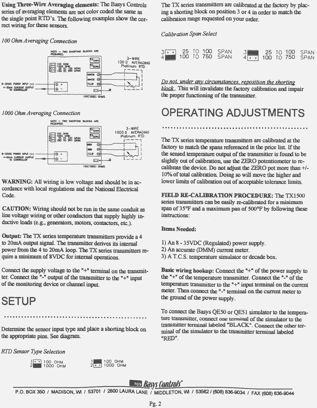
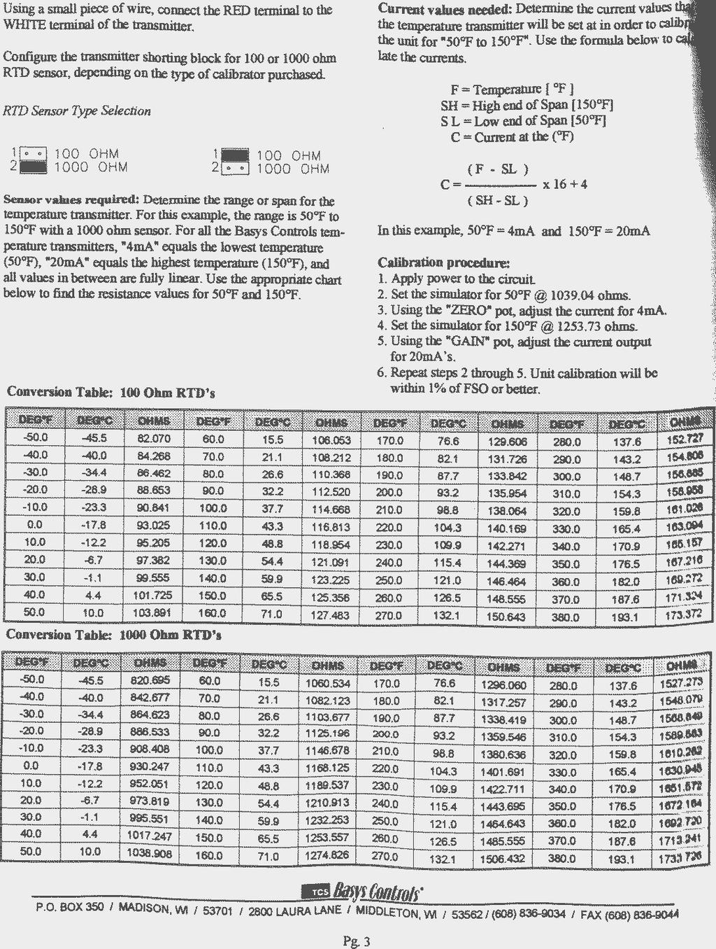
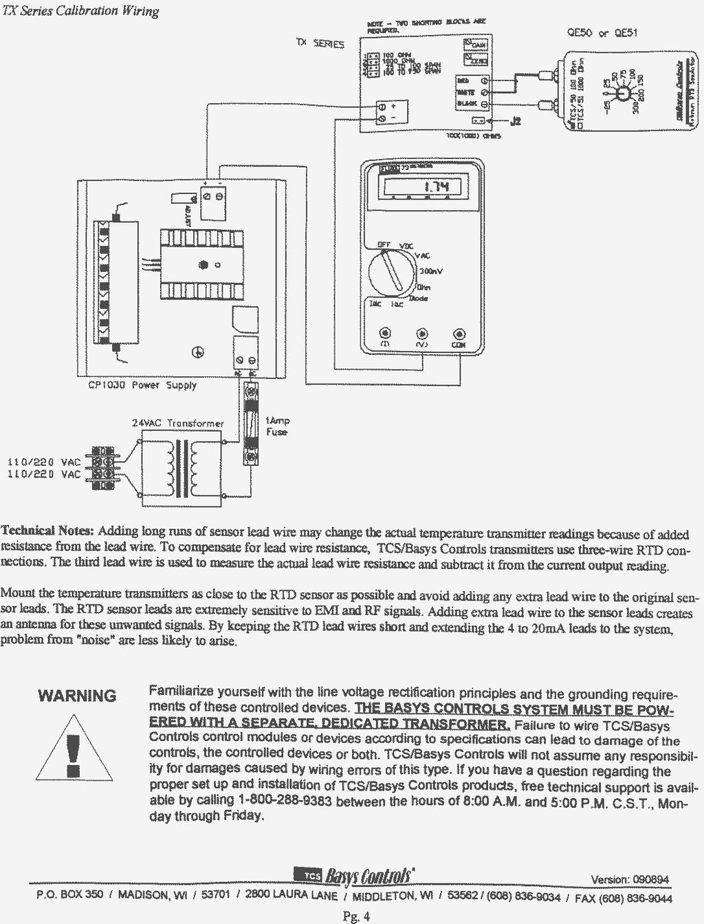
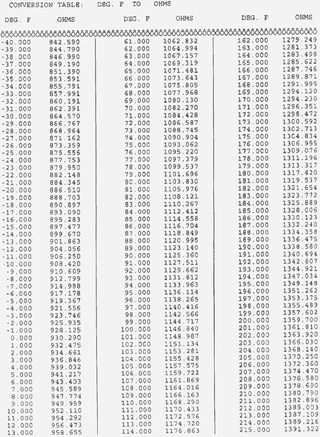
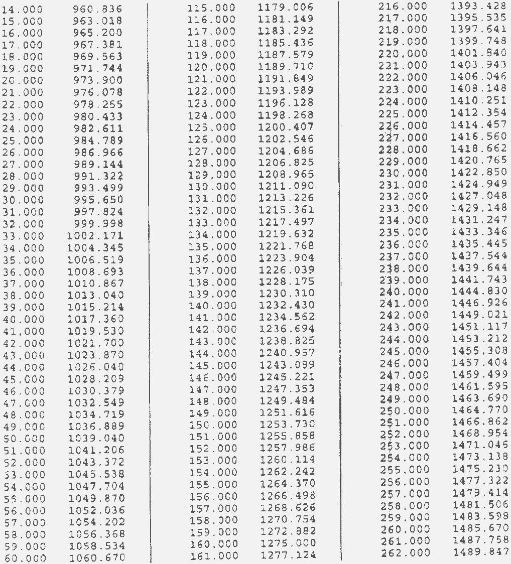
1 TRANSMITTER CALIBRATION In this laboratory study, you will be asked to calibrate two of four different devices. To do so, you will need to write the equation defining the performance of the unit. Use this equation to predict the output of the unit with a known value of input. The transmitters under study are: TCS Model TX1504 temperature transmitter calibrated for an RTD input. The input range is either o F or o F. The output range is 420 ma. This is a loop powered current device requiring an input voltage of 835 VDC. Contractor Instruments Model P855 static pressure transmitter. Input range is either 0 to 3 in w.g. or 0.25 to 1.75 in w.g. The output range is 4 to 20 ma. This is a loop powered current device requiring an input voltage of 840 VDC. Omega Model FLSC18B flow transmitter designed for use with any number of their flow sensors. This particular transducer is a loop powered current device with a 4 to 20 ma output. The input signal is the frequency of a magnetic pulse as output from the flow sensor. PROCEDURE In all cases, you must first be able to determine the output of the device for a given input. If the manufacturer does not provide a table, you can develop the equation for the device. The equation should be written so as to predict the transmitter output with a known input of simulated temperature, pressure or flow. TCS Model TX1504 The input to the transmitter will be a resistance. The attached table correlates resistance to temperature for a 1000 Ω sensor. Select two appropriate resistors. Do not rely on the stated rating of the resistor. Use a multimeter to measure its resistance. Once the actual resistance of each is measured, determine what temperature this represents. For example, assume you selected a resistor with a resistance of Ω. Referring to the attached resistance table, note this falls between 92 o F and 93 o F. Interpolating, we find: * ( 93 92) 92 = Using the equation you developed, you can now predict the output of the transmitter. o F If a desired resistance cannot be found, you can parallel two resistors to obtain that desired resistance. To determine the resistance of two resistors in parallel, remember that: = R R R 1 2 where: R=desired resistance R 1 = resistance of first resistor R 2 = resistance of second resistor Connect the device as shown below. Ensure the device is properly configured for a 1000 Ω sensor and a 200 o F temperature span as shown in the attached specification sheet. Your instructor will inspect the wiring prior to switching on the power supply.
2 Power Supply Milliamp Meter R W B SENSOR Signal is B to W Terminal R is compensating Note: Replace sensor with a resistor during calibration. With the power supply off, connect the resistor of the lowest value to the input terminals (B to W) or (B to R) of the transducer. Before switching on the power supply, ensure the proper voltage range is selected and the voltage output is turned down. Turn the voltage up on the power supply while monitoring it with the builtin voltmeter or a handheld multimeter until you read 24 VDC. Current output will read on the analog milliamp meter. Adjust the zero pot on the transducer until you read your desired milliamp output. Now switch the power off, replace the resistor with a higher value and turn the power back on. Adjust the span pot to read the desired value of current output. Repeat the procedure by switching resistors and adjusting zero and span until they settle out to the desired values. The transducer is now calibrated. Check your calibration by connecting any value of resistance that falls within the specified input range and observe the output. Is this what you expect? CAUTION We have found the TCS transducers often calibrate just the opposite of what is normally expected. In other words, you may need to adjust the zero pot with the high resistance connected and the span pot with the low resistance connected. CONTRACTOR INSTRUMENTS Model P855 The Contractor Instruments static pressure transmitter accepts wither a 03 in w.g. or in w.g. static pressure as stated on the nameplate. The output is 420 ma. Connect the transmitter as shown in the diagram below. Apply Pressure Here Power Supply LO HI Manometer Milliamp Meter Pressure input will be measured with an Airflow Manometer. Connect a tube to the high port of the transmitter and the manometer so they both read static pressure. Be extremely cautious of attaching and removing tubes from the sensor. The barbs are plastic and break easily. By blowing into the tube, apply a pressure to the manometer/transmitter close to the upper end of its range and pinch it off with a pair of vice grips. Read the pressure on the manometer and the current from the milliamp meter. Based
3 on the equation you developed for this unit, determine what current you should be reading. Adjust the span pot as necessary to read the proper voltage. Now release the pressure. This should be zero pressure. Read the current. If it is not what you expect, adjust the zero pot. Repeat the procedure by alternating between zero pressure and any other pressure (close to the upper end of the sensor span) until the readings settle out to what you ve calculated. The transmitter is now calibrated. Check your calibration by applying any pressure within the range of the transmitter and observing the current. Is the current what you expect? OMEGA Model FLSC18B The input to the transducer will be a pulse at a certain frequency. The attached table correlates pulse frequency with flow in gpm. Select two appropriate values of input frequency. Determine the appropriate gpm flow these values represent and the current output of the transducer. Connect the device as shown below. The 180 Ω resistor simulates the receiver display or the controller. 1 2 Leads FUNCTION GENERATOR Power Supply 180 Ω FREQUENCY COUNTER Milliamp Meter Select a square wave output on the function generator and adjust the output to your desired frequency. Use the frequency counter to measure the frequency output of the function generator. Set the frequency counter for DC Coupling, 20X attenuation, and LP (Low Pass) filter on. These settings will filter out the electrical noise within the lab as a result of the fluorescent lighting and the effects of the local radio stations (RF Interference). With the output of the function generator on low frequency, measure the output of the transmitter on the milliamp meter. Adjust the zero pot if necessary. Change the output of the function generator to your desired high frequency. Measure the output of the transmitter. Adjust the span as necessary to obtain the desired output. Repeat the procedure by alternating between high and low frequencies until the readings settle out to what is calculated. The transmitter is now calibrated. Check your calibration by applying any other frequency within the range of the transmitter and observing the output. Is the output what you expect?
4
5
6
7
8
9
10
TI25 - Pre-Instructional Survey
 TI25 - Pre-Instructional Survey Name: Date: 1. Scheduled maintenance that is planned, with materials on hand, personnel on site, and production planning advised is called maintenance. a. predictive b.
Department of Mechanical and Aerospace Engineering. MAE334 - Introduction to Instrumentation and Computers. Final Examination.
 Name: Number: Department of Mechanical and Aerospace Engineering MAE334 - Introduction to Instrumentation and Computers Final Examination December 12, 2002 Closed Book and Notes 1. Be sure to fill in your
BASIC TECHNIQUES FOR ACCURATE RESISTANCE MEASUREMENT WHITE PAPER. Reduce Measurement Errors in your Application
 BASIC TECHNIQUES FOR ACCURATE RESISTANCE MEASUREMENT Reduce Measurement Errors in your Application At CAS DataLoggers we often receive calls from users working in resistance measurement applications, for
WATER METERS M SERIES WATER METERS INSTALLATION, OPERATION AND MAINTENANCE GUIDE METAL M SERIES WATER METER PLASTIC M SERIES WATER METER
 WATER METERS M SERIES WATER METERS INSTALLATION, OPERATION AND MAINTENANCE GUIDE METAL M SERIES WATER METER PLASTIC M SERIES WATER METER INTRODUCTION M SERIES WATER METERS INDUSTRY S SMALLEST WATER METERS
HUMITRAN-RHT & RH RELATIVE HUMIDITY/TEMPERATURE TRANSMITTER RELATIVE HUMIDITY TRANSMITTER
 HUMITRAN-RHT & RH RELATIVE HUMIDITY/TEMPERATURE TRANSMITTER RELATIVE HUMIDITY TRANSMITTER A. GENERAL DESCRIPTION The Tegam Model RH is a relative humidity transmitter; the Model RHT includes a temperature
EE 241 Experiment #4: USE OF BASIC ELECTRONIC MEASURING INSTRUMENTS, Part III 1
 EE 241 Experiment #4: USE OF BASIC ELECTRONIC MEASURING INSTRUMENTS, Part III 1 PURPOSE: To become familiar with more of the instruments in the laboratory. To become aware of operating limitations of input
Exercise 2: Temperature Measurement
 Exercise 2: Temperature Measurement EXERCISE OBJECTIVE When you have completed this exercise, you will be able to explain the use of a thermocouple in temperature measurement applications. DISCUSSION the
EE283 Laboratory Exercise 1-Page 1
 EE283 Laboratory Exercise # Basic Circuit Concepts Objectives:. To become familiar with the DC Power Supply unit, analog and digital multi-meters, fixed and variable resistors, and the use of solderless
Introduction to Electronic Equipment
 Introduction to Electronic Equipment INTRODUCTION This semester you will be exploring electricity and magnetism. In order to make your time in here more instructive we ve designed this laboratory exercise
Group: Names: Resistor Band Colors Measured Value ( ) R 1 : 1k R 2 : 1k R 3 : 2k R 4 : 1M R 5 : 1M
 R 1 : 1k R 2 : 1k R 3 : 2k R 4 : 1M R 5 : 1M") 2.4 Laboratory Procedure / Summary Sheet Group: Names: (1) Select five separate resistors whose nominal values are listed below. Record the band colors for each resistor in the table below. Then connect
2.4 Laboratory Procedure / Summary Sheet Group: Names: (1) Select five separate resistors whose nominal values are listed below. Record the band colors for each resistor in the table below. Then connect
Differential Amplifier : input. resistance. Differential amplifiers are widely used in engineering instrumentation
 Differential Amplifier : input resistance Differential amplifiers are widely used in engineering instrumentation Differential Amplifier : input resistance v 2 v 1 ir 1 ir 1 2iR 1 R in v 2 i v 1 2R 1 Differential
MARMARA UNIVERSITY CSE315 DIGITAL DESIGN LABORATORY MANUAL. EXPERIMENT 7: Analog-to-Digital Conversion. Research Assistant Müzeyyen KARAMANOĞLU
 MARMARA UNIVERSITY CSE315 DIGITAL DESIGN LABORATORY MANUAL EXPERIMENT 7: Analog-to-Digital Conversion Research Assistant Müzeyyen KARAMANOĞLU Electrical&Electronics Engineering Department Marmara University
Exercise 3: Voltage in a Series Resistive Circuit
 DC Fundamentals Series Resistive Circuits Exercise 3: Voltage in a Series Resistive Circuit EXERCISE OBJECTIVE When you have completed this exercise, you will be able to determine the voltage in a series
To Calibrate or Not to Calibrate a fieldbus transmitter? Dale Perry Pressure Marketing Manager Rosemount
 To Calibrate or Not to Calibrate a fieldbus transmitter? Dale Perry Pressure Marketing Manager Rosemount Introduction Digital Transmitters are here Wireless Fieldbus Same architecture as Smart-HART transmitter
EE 448 Fall Lab Experiment No. 3 04/04/2008. Transformer Experiment
 EE 8 Laboratory Experiment 3 EE 8 Fall 2008 Lab Experiment No. 3 0/0/2008 1 I. INTRODUCTION OBJECTIVES: EE 8 Laboratory Experiment 3 1. To learn how real world transformers operate under ideal conditions.
Laboratory Exercise - Seven
 Basic D.C. AVIM 121 Lab 7 Page 1 of 9 rev. 08.09 Laboratory Exercise - Seven Objectives Determine milliammeter equivalent resistance. Calculate and apply meter shunts and multipliers. Determine voltmeter
Pre-Lab for Batteries and Bulbs
 Pre-Lab for Batteries and Bulbs Complex circuits composed of resistors can be simplified by using the concept of equivalent resistors. For example if resistors R 1, R 2, and R 3 are connected in series,
Ohm s Law and Electrical Circuits
 Ohm s Law and Electrical Circuits INTRODUCTION In this experiment, you will measure the current-voltage characteristics of a resistor and check to see if the resistor satisfies Ohm s law. In the process
Configurations of Resistors
 Configurations of Resistors Safety and Equipment Multimeter with probes or banana leads. Two of 50Ω and one of 100Ω resistors 5 connecting wires with double alligator clips Introduction There are two basic
The Art of Electrical Measurements
 The Art of Electrical Measurements Purpose: Introduce fundamental electrical test and measurement tools and the art of making electrical measurements. Equipment Required Prelab 1 Digital Multimeter 1 -
Electric Transformer. Specifically, for each coil: Since the rate of change in flux through single loop of each coil are approximately the same,
 Electric Transformer Safety and Equipment Computer with PASCO 850 Universal Interface and PASCO Capstone Coils Set 3 Double Banana Cables PASCO Voltage Sensor (DIN to Banana cable with slip-on Alligator
Process Calibrator. TechChek 820
 Process Calibrator TechChek 80 CONTENTS GENERAL... TURN ON... CONNECTIONS... TILT STAND...4 CHANGING BATTERIES...4 RESTORING DEFAULT SETTINGS... CONFIGURING TEMPERATURE SCALES... ENABLING AUTO-OFF... SELECTING
PAD - Heavy Duty Differential Pressure Trasmitter
 Benefits and Features Span: 0.3" W.C. 6" W.C. to 60 6000 PSIG Static Pressure: Max. 4500 PSIG t max : 248 F Process Connection: ½" NPT, ¼" NPT, or Various Diaphragm Seals Available upon Request Material:
DSTS-3B DEPTHSOUNDER TEST SET OPERATOR S MANUAL
 Page 1 1.0 INTRODUCTION DSTS-3B DEPTHSOUNDER TEST SET OPERATOR S MANUAL The DSTS-3B is a full-featured test set designed for use with all types of echo sounders from small flashers to large commercial
MFJ ENTERPRISES, INC.
 TM Model MFJ-1924 INSTRUCTION MANUAL CAUTION: Read All Instructions Before Operating Equipment! MFJ ENTERPRISES, INC. 300 Industrial Park Road Starkville, MS 39759 USA Tel: 662-323-5869 Fax: 662-323-6551
Ohm s and Kirchhoff s Circuit Laws. Abstract. Introduction and Theory. EE 101 Spring 2006 Date: Lab Section #: Lab #2
 EE 101 Spring 2006 Date: Lab Section #: Lab #2 Name: Ohm s and Kirchhoff s Circuit Laws Abstract Rev. 20051222JPB Partner: Electrical circuits can be described with mathematical expressions. In fact, it
April 1994 UCM-420A. Setpoint Controller. Operating and Installation Instructions
 April TM UCM-A Setpoint Controller Operating and Installation Instructions A LARGE number of applications in a SMALL package... REMOTE SETPOINT CONTROLLER LOCAL SETPOINT CONTROLLER - ma SIGNAL GENERATOR
Resistance and Ohm s law
 Resistance and Ohm s law Objectives Characterize materials as conductors or insulators based on their electrical properties. State and apply Ohm s law to calculate current, voltage or resistance in an
Series APD4059. For Load Cells/Pressure Transducer Transmitters. Field Rangeable, with Calibration Resistor. Standard Features.
 TECHNICAL MANUAL Series APD4059 For Load Cells/Pressure Transducer Transmitters. Field Rangeable, with Calibration Resistor Standard Features Use Internal or External Calibration Resistor Sense Lead Compensation
KING-GAGE KING. ES2 Liquid Level Transmitter. Installation and Operation Instructions ma Liquid Level Transmitter EX-1834
 Effective: April 2007 (Replaces January 2007) KING-GAGE 4-20 ma Liquid Level Transmitter ES2 Liquid Level Transmitter Installation and Operation Instructions Since 1937 KING E N G I N E E R I N G C O R
User manual Firmware V1.0-V1.2 HTB230. In-head transmitter
 User manual 18.2.2013 Firmware V1.0-V1.2 HTB230 In-head transmitter 1 INTRODUCTION Nokeval HTB230 is a basic level in-head transmitter for RTD sensors. The range and sensor type are programmable using
5. Transducers Definition and General Concept of Transducer Classification of Transducers
 5.1. Definition and General Concept of Definition The transducer is a device which converts one form of energy into another form. Examples: Mechanical transducer and Electrical transducer Electrical A
Wiring and Measuring 4-20mA Instruments
 5 Gould Road, PO Box 2155 New London, NH 03257 USA Voice: (603) 526-9800 info@canarysystems.com www.canarysystems.com Wiring and Measuring 4-20mA Instruments Sensor Application Note #33 - Revision 1/24/2019
Exercise 2: Ohm s Law Circuit Current
 Exercise 2: Circuit Current EXERCISE OBJECTIVE When you have completed this exercise, you will be able to determine current by using Ohm s law. You will verify your results with a multimeter. DISCUSSION
Process Multimeter DPM 79
 NEW! Processmeter is a handheld, battery operated tool for measuring & simulation of electrical parameters. It has all the features of a digital multimeter (including the feature of RTD and TC) and it
Using Circuits, Signals and Instruments
 Using Circuits, Signals and Instruments To be ignorant of one s ignorance is the malady of the ignorant. A. B. Alcott (1799-1888) Some knowledge of electrical and electronic technology is essential for
Economical Digital Indicators For Process and Electrical Measurement
 Economical Digital Indicators For Process and Electrical Measurement DP18 Series Panel Punches Available DP18-P5, 4 to 20 ma input. DP18-EC, thermocouple input visit omega.com/thermocouple for thermocouples.
Isolated, Linearized RTD Input 7B34 FEATURES APPLICATIONS PRODUCT OVERVIEW FUNCTIONAL BLOCK DIAGRAM
 Isolated, Linearized RTD Input 7B34 FEATURES Amplifies, Protects, Filters, and interfaces input voltages from a wide variety of two and three-wire platinum, copper and nickel Resistor Temperature Detectors
W100/W600/W900 Controller ph Electrode Troubleshooting Guide
 W100/W600/W900 Controller ph Electrode Troubleshooting Guide Table of Contents Section 1 Section 2 Section 3 Section 4 Section 5 Electrode Reading Responds Slowly Electrode Reading is Stuck on one Value
INSTALLATION & OPERATION MANUAL
 INSTALLATION & OPERATION MANUAL AN25 Totalizer/ Rate Indicator DOC#: MN-AN25.doc Sponsler Co., Inc. AN25 Totalizer/Rate Indicator pg. 2 DOC#: MN-AN25 SPECIFICATIONS Temperature: Operating 0 to 70 C Storage
PHYS 1112L - Introductory Physics Laboratory II
 PHYS 1112L - Introductory Physics Laboratory II Laboratory Advanced Sheet dc Circuits 1. Objectives. The objectives of this laboratory are a. to be able to construct dc circuits given a circuit diagram
DRG-SC Series Signal Conditioners
 DRG-SC Series Signal Conditioners DRG-SC Series 245 Basic unit Models Available for Thermocouples, RTDs, DC Voltage and Current, Frequency, Strain Gage Bridge, AC Voltage and Current Field Configurable
User s Guide FLSC-45/45B. Paddlewheel Signal Conditioner. Shop online at omega.com
 TM User s Guide Shop online at omega.com e-mail: info@omega.com For latest product manuals: www.omegamanual.info NORWALK, CT FLSC-45/45B Paddlewheel Signal Conditioner omega.com info@omega.com U.S.A. Headquarters:
ECE 317 Laboratory #1 Force Sensitive Resistors
 ECE 317 Laboratory #1 Force Sensitive Resistors Background Force, pressure, and position sensing are required for a wide variety of uses. In this lab, we will investigate a sensor called a force sensitive
Instrument Usage in Circuits Lab
 Instrument Usage in Circuits Lab This document contains descriptions of the various components and instruments that will be used in Circuit Analysis laboratory. Descriptions currently exist for the following
Basic Electronics. Chapter 2 Basic Electrical Principles and the Functions of Components. PHYS 401 Physics of Ham Radio
 Basic Electronics Chapter 2 Basic Electrical Principles and the Functions of Components Figures in this course book are reproduced with the permission of the American Radio Relay League. This booklet was
CA330 RTD Calibrator: High-speed Response and High-resolution Resistance Simulator
 CA33 RTD Calibrator: High-speed Response and High-resolution Resistance Simulator CA33 RTD Calibrator: High-speed Response and High-resolution Resistance Simulator Kouki Shouji *1 Yokogawa Meters & Instruments
ANALOG SCALING MODULE
 ANALOG SCALING MODULE FEATURES 24V AC operation Output can sink input s pull-up voltage Optional Zero & Span potentiometers Small size 1.10" by 2.19" Two mounting options APPLICATIONS Analog 0 to 5V DC
Operating Manual. Differential Pressure Transmitter DPS 100
 Operating Manual Differential Pressure Transmitter DPS 100 Important notes: Please read this operating manual carefully before installing and starting up the pressure transmitter. This operating manual
SHRI ANGALAMMAN COLLEGE OF ENGINEERING & TECHNOLOGY (An ISO 9001:2008 Certified Institution) SIRUGANOOR,TRICHY
 SIRUGANOOR,TRICHY") SHRI ANGALAMMAN COLLEGE OF ENGINEERING & TECHNOLOGY (An ISO 9001:2008 Certified Institution) SIRUGANOOR,TRICHY-621105. DEPARTMENT OF ELECTRICAL AND ELECTRONICS ENGINEERING EI 1306-MEASUREMENT AND INSTRUMENTATION
SHRI ANGALAMMAN COLLEGE OF ENGINEERING & TECHNOLOGY (An ISO 9001:2008 Certified Institution) SIRUGANOOR,TRICHY-621105. DEPARTMENT OF ELECTRICAL AND ELECTRONICS ENGINEERING EI 1306-MEASUREMENT AND INSTRUMENTATION
PIE 525. Diagnostic Thermocouple RTD & Milliamp Calibrator Operating Instructions. Practical Instrument Electronics
 PIE 525 Diagnostic Thermocouple RTD & Milliamp Calibrator Operating Instructions Practical Instrument Electronics Tel: 585.872.9350 Fax: 585.872.2638 sales@piecal.com www.piecal.com Contents General Operations
MEASUREMENTS & INSTRUMENTATION ANALOG AND DIGITAL METERS
 MEASUREMENTS & INSTRUMENTATION ANALOG AND DIGITAL METERS ANALOG Metering devices Provides monotonous (continuous) movement. ELECTRICAL MEASURING INSTRUMENTS ANALOG METERS A d Arsonval galvanometer (Moving
SIGNAL INTERFACE MODULE
 SIGNAL INTERFACE MODULE FEATURES Optically isolated inputs Field adjustable output Second onboard DC supply Positive / negative voltage output APPLICATIONS Phase cut to ma / VDC conversion Signal scaling
Princo MagneLevel Model LML
 Instrumentation designed with the user in mind Instruction Manual Princo MagneLevel Model LML Two-Wire Magnetic Coupled Level Transmitter 11 Nov 05 PRINCO INSTRUMENTS INC., 1020 INDUSTRIAL BLVD., SOUTHAMPTON,
MFJ ENTERPRISES, INC.
 Screwdriver Antenna Controller Model MFJ-1926 INSTRUCTION MANUAL CAUTION: Read All Instructions Before Operating Equipment! MFJ ENTERPRISES, INC. 300 Industrial Park Road Starkville, MS 39759 USA Tel:
User manual V1.0 RTB231 RTB232. RTD transmitter
 User manual 26.9.2007 V1.0 RTB231 RTB232 RTD transmitter 1 INTRODUCTION RTB231 and RTB232 are basic level DIN rail mounted transmitter for RTD sensors. The range and sensor type are programmable using
Laboratory 2 (drawn from lab text by Alciatore)
") Laboratory 2 (drawn from lab text by Alciatore) Instrument Familiarization and Basic Electrical Relations Required Components: 2 1k resistors 2 1M resistors 1 2k resistor Objectives This exercise is designed
Laboratory 2 (drawn from lab text by Alciatore) Instrument Familiarization and Basic Electrical Relations Required Components: 2 1k resistors 2 1M resistors 1 2k resistor Objectives This exercise is designed
SENSOR AND MEASUREMENT EXPERIMENTS
 SENSOR AND MEASUREMENT EXPERIMENTS Page: 1 Contents 1. Capacitive sensors 2. Temperature measurements 3. Signal processing and data analysis using LabVIEW 4. Load measurements 5. Noise and noise reduction
CEC VIBRATION TRANSMITTER
 CEC 1-808 VIBRATION TRANSMITTER Operation & Maintenance Manual 746 Arrow Grand Circle Covina, CA 91722 United States of America Tel: (626) 938-0200 Fax: (626) 938-0202 Internet: http://www.cecvp.com E-mail:
Temperature Transmitters - Head Mounted
 XTH Features - Non-programmable Models Sensor Types: Models for thermocouple Types J, K, or T Models for RTD Type Pt100 3-wire Select from a variety of pre-configured measuring ranges Internal cold junction
Current, resistance, and Ohm s law
 Current, resistance, and Ohm s law Apparatus DC voltage source set of alligator clips 2 pairs of red and black banana clips 3 round bulb 2 bulb sockets 2 battery holders or 1 two-battery holder 2 1.5V
Lab 11: Circuits. Figure 1: A hydroelectric dam system.
 Description Lab 11: Circuits In this lab, you will study voltage, current, and resistance. You will learn the basics of designing circuits and you will explore how to find the total resistance of a circuit
AMERITRON SDC-102 Screwdriver Antenna Controller
 AMERITRON SDC-102 Screwdriver Antenna Controller INSTRUCTION MANUAL PLEA S E REA D T H IS M A NU A L BEFORE OP ERA T I N G T H IS EQU IP M EN T! 116 Willow Road Starkville, MS 39759 USA 662-323-8211 Version
KING-GAGE. D/P Transmitter 4-20 ma Pressure Transmitter ma Pressure Transmitter. Operation/Calibration Manual
 Effective: August, 2009 (January, 2007) KING-GAGE 4-20 ma Pressure Transmitter D/P Transmitter 4-20 ma Pressure Transmitter Operation/Calibration Manual User Guide to Range Calculation, Calibration Procedures,
CX105 Conductivity/Resistivity Transmitter
 CX105 Conductivity/Resistivity Transmitter User Manual REV A.15 Sensorex Corporation, USA 11751 Markon Drive Garden Grove, CA. 92841 U.S.A. www.sensorex.com IMPORTANT SAFETY INFORMATION Please read and
INSTALLATION & OPERATION MANUAL
 INSTALLATION & OPERATION MANUAL Analog Signal Conditioner Rev. C Page 0 GENERAL DESCRIPTION: The frequency to current/voltage converter is designed to be a general purpose signal conditioner. The signal
MEASUREMENT AND INSTRUMENTATION QUESTION BANK UNIT I INTRODUCTION. Part A
 MEASUREMENT AND INSTRUMENTATION QUESTION BANK UNIT I INTRODUCTION Part A 1. Define Standard deviation. 2. Why calibration of instrument is important? 3. What are the different calibration methodologies?
Motomatic Servo Control
 Exercise 2 Motomatic Servo Control This exercise will take two weeks. You will work in teams of two. 2.0 Prelab Read through this exercise in the lab manual. Using Appendix B as a reference, create a block
50 Ω Dummy Load for Transmitter testing and experiments
 50 Ω Dummy Load for Transmitter testing and experiments Many thanks for purchasing this dummy load, it has been designed to provide constant 50 Ω impedance to a radio transmitter to allow off air tests
Installation and Operating Manual
 GB Analog Weight Transmitter PS-1000 Installation and Operating Manual LIST OF CONTENTS Section 1, General information Introduction... 3 Description... 3 Specifications... 4 Wiring connections... 5 Section
Basic Electronics. Chapter 2, 3A (test T5, T6) Basic Electrical Principles and the Functions of Components. PHYS 401 Physics of Ham Radio
 Basic Electrical Principles and the Functions of Components. PHYS 401 Physics of Ham Radio") Basic Electronics Chapter 2, 3A (test T5, T6) Basic Electrical Principles and the Functions of Components Figures in this course book are reproduced with the permission of the American Radio Relay League.
Basic Electronics Chapter 2, 3A (test T5, T6) Basic Electrical Principles and the Functions of Components Figures in this course book are reproduced with the permission of the American Radio Relay League.
EKT 314/4 LABORATORIES SHEET
 EKT 314/4 LABORATORIES SHEET WEEK DAY HOUR 4 1 2 PREPARED BY: EN. MUHAMAD ASMI BIN ROMLI EN. MOHD FISOL BIN OSMAN JULY 2009 Creating a Typical Measurement Application 5 This chapter introduces you to common
December 2014 Ed 21. Testing and Recalibration
 Testing and Recalibration Testing and Recalibration of the MAS2600 37 MAS2600: Testing and Recalibration Ed 21 December 2014 Testing Before dispatch, the MAS2600 transmitter is calibrated in accordance
CPE 100L DIGITAL LOGIC DESIGN I DESIGN LABORATORY LABORATORY 1 LAB SAFETY QUIZ & LAB EQUIPMENT USE TUTORIAL UNIVERSITY OF NEVADA, LAS VEGAS GOALS:
 CPE 100L DESIGN LABORATORY LABORATORY 1 LAB SAFETY QUIZ & LAB EQUIPMENT USE TUTORIAL DEPARTMENT OF ELECTRICAL AND COMPUTER ENGINEERING UNIVERSITY OF NEVADA, LAS VEGAS GOALS: Introduce laboratory safety
NOVATO (MAXREFDES16#): 4-20MA LOOP-POWERED TEMPERATURE SENSOR WITH HART
: 4-20MA LOOP-POWERED TEMPERATURE SENSOR WITH HART") System Board 5817 NOVATO (MAXREFDES16#): 4-20MA LOOP-POWERED TEMPERATURE SENSOR WITH HART Introduction Temperature is one of the most widely measured parameters in industrial process control and automation.
System Board 5817 NOVATO (MAXREFDES16#): 4-20MA LOOP-POWERED TEMPERATURE SENSOR WITH HART Introduction Temperature is one of the most widely measured parameters in industrial process control and automation.
LABORATORY MODULE. Analog Electronics. Semester 2 (2005/2006)
") LABORATORY MODULE ENT 162 Analog Electronics Semester 2 (2005/2006) EXPERIMENT 1 : Introduction to Diode Name Matric No. : : PUSAT PENGAJIAN KEJURUTERAAN MEKATRONIK KOLEJ UNIVERSITI KEJURUTERAAN UTARA
LABORATORY MODULE ENT 162 Analog Electronics Semester 2 (2005/2006) EXPERIMENT 1 : Introduction to Diode Name Matric No. : : PUSAT PENGAJIAN KEJURUTERAAN MEKATRONIK KOLEJ UNIVERSITI KEJURUTERAAN UTARA
RTD and thermocouple circuits, with millivolt calculations
 RTD and thermocouple circuits, with millivolt calculations This worksheet and all related files are licensed under the Creative Commons ttribution License, version 1.0. To view a copy of this license,
STATION NUMBER: LAB SECTION: RC Oscillators. LAB 5: RC Oscillators ELECTRICAL ENGINEERING 43/100. University Of California, Berkeley
 YOUR NAME: YOUR SID: Lab 5: RC Oscillators EE43/100 Spring 2013 Kris Pister YOUR PARTNER S NAME: YOUR PARTNER S SID: STATION NUMBER: LAB SECTION: Pre- Lab GSI Sign- Off: Pre- Lab Score: /40 In- Lab Score:
Lab Exercise # 9 Operational Amplifier Circuits
 Objectives: THEORY Lab Exercise # 9 Operational Amplifier Circuits 1. To understand how to use multiple power supplies in a circuit. 2. To understand the distinction between signals and power. 3. To understand
Technician License Course Chapter 3. Lesson Plan Module 4 Electricity
 Technician License Course Chapter 3 Lesson Plan Module 4 Electricity Fundamentals of Electricity Radios are powered by electricity and radio signals are a form of electrical energy. A basic understanding
// Parts of a Multimeter
 Using a Multimeter // Parts of a Multimeter Often you will have to use a multimeter for troubleshooting a circuit, testing components, materials or the occasional worksheet. This section will cover how
Interfacing the 1250B, 1250LTC and 1511-LTC Monitors to the Beckwith Tapchanger Controller
 INTELLIGENT CONTROLS INC PO BOX 638 34 SPRING HILL RD SACO, ME 04072 USA Application Bulletin 000-2060 Rev B Interfacing the 1250B, 1250LTC and 1511-LTC Monitors to the Beckwith Tapchanger Controller Introduction:
EELE 354 Lab Assignment 2: Electric Heater - Power Measurements and Considerations
 EELE 354 Lab Assignment 2: Electric Heater - Power Measurements and Considerations EELE 354 Lab Assignment 2 1 Lab Overview: In this lab, students will simulate the operation of a resistive electric heater.
KING-GAGE. D/P Transmitter 4 20 ma Pressure Transmitter ma Pressure Transmitter. Operation/Calibration Manual
 ffective: eptember, 2010 (August, 2009) KING-GAG 4 20 ma Pressure Transmitter D/P Transmitter 4 20 ma Pressure Transmitter Operation/Calibration Manual User Guide to Range Calculation, Calibration Procedures,
MFJ-219/219N 440 MHz UHF SWR Analyzer TABLE OF CONTENTS
 MFJ-219/219N 440 MHz UHF SWR Analyzer TABLE OF CONTENTS Introduction...2 Powering The MFJ-219/219N...3 Battery Installation...3 Operation Of The MFJ-219/219N...4 SWR and the MFJ-219/219N...4 Measuring
PHYS 1112L - Introductory Physics Laboratory II
 PHYS 1112L - Introductory Physics Laboratory II Laboratory Advanced Sheet Galvanometers and Voltmeters 1. Objectives. The objectives of this laboratory are a. to be able to characterize a galvanometer
Curriculum. Technology Education ELECTRONICS
 Curriculum Technology Education ELECTRONICS Supports Academic Learning Expectation # 3 Students and graduates of Ledyard High School will employ problem-solving skills effectively Approved by Instructional
Lab 3: Digital Multimeter and Voltage Generator
 Lab 3: Digital Multimeter and Voltage Generator Lab Goals: Learn how to use your mydaq as a Digital Multimeter (DMM) Learn how to output a signal to a specified output port on the mydaq and verify its
Module 1, Lesson 2 Introduction to electricity. Student. 45 minutes
 Module 1, Lesson 2 Introduction to electricity 45 minutes Student Purpose of this lesson Explanations of fundamental quantities of electrical circuits, including voltage, current and resistance. Use a
ELE.B: Original Assignment Resistors in Series Classwork Homework
 ELE.B: Original Assignment Resistors in Series Classwork 1. A 3 Ω resistor is connected in series to a 6 Ω resistor and a 12-V battery. What is the current in each of the resistors? What is the voltage
DC Electric Circuits: Resistance and Ohm s Law
 DC Electric Circuits: Resistance and Ohm s Law Goals and Introduction Our society is very reliant on electric phenomena, perhaps most so on the utilization of electric circuits. For much of our world to
= 7 volts Copyright , R. Eckweiler & OCARC, Inc. Page 1 of 5
 by Bob Eckweiler, AF6C Ohm s Law (Part II of IV): Thévenin s Theorem: Last month the three forms of Ohm s Law were introduced. For simple circuits the law is easy to apply, as we saw in the examples and
KING-GAGE ES2. Installation and Operation Instructions Manual. Electronic Liquid Level Transmitter. ESR Serial No. Versions and Slimline Versions
 Effective: November 2009 (replaces August 2009) KING-GAGE ES2 Electronic Liquid Level Transmitter Installation and Operation Instructions Manual ESR Serial No. Versions and Slimline Versions 2009 King
Experiment 1: Instrument Familiarization (8/28/06)
") Electrical Measurement Issues Experiment 1: Instrument Familiarization (8/28/06) Electrical measurements are only as meaningful as the quality of the measurement techniques and the instrumentation applied
Electrical Measurement Issues Experiment 1: Instrument Familiarization (8/28/06) Electrical measurements are only as meaningful as the quality of the measurement techniques and the instrumentation applied
Loop calibration and maintenance
 Loop calibration and maintenance pplication Note Introduction Process instrumentation requires periodic calibration and maintenance to ensure that it is operating correctly. This application note contains
OPTITEMP TT 20 Technical Datasheet
 OPTITEMP TT 20 Technical Datasheet Analog PC-programmable two-wire transmitters for Pt100 Efficient PC-configuration without recalibration Very stable output Very fast response time The documentation is
Ultra Precise Immersion RTD Sensors
 Ultra Precise Immersion RTD Sensors Starts at 32 75 UK P-M-A-3-25-G/4-P-, 55.25, shown smaller m of 4-wire, 7/0. stranded cable with stripped ends standard (see table for insulation options) 00 Ω Platinum
 Page 1 of 6 A Historical Perspective From Aristotle to Hawking Force & Its Effects Measurement Limitations The Strain Gage Sensor Designs Measuring Circuits Application & Installation Process Pressure
Series and Parallel Resistors
 Lab 8. Series and Parallel Resistors Goals To understand the fundamental difference between resistors connected in series and in parallel. To calculate the voltages and currents in simple circuits involving
WATT TRANSDUCER. Instruction Manual
 WT 9200 WATT TRANSDUCER Instruction Manual IM-2 September 2003 USA: 6428 Ridglea Drive, Watauga, Texas 76148 Tel/Fax 1-817-427-2060/2067 E-mail: wes@westecinstruments.com SPECIFICATIONS Power Supply Input