Designing 100kHz, flyback transformers for input voltage vdc and power up to 500W
|
|
|
- Gregory Norman
- 5 years ago
- Views:
Transcription
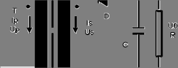
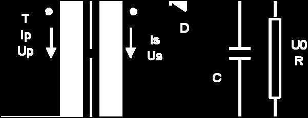
1 In the beginning Designing 100kHz, flyback transformers for input voltage vdc and power up to 500W Thirty years ago, designers calculated transformers on their pocket calculators. The designer had to pencil in all the input and output fields onto a form and then feed them into the calculator. Today, he can forget the pencil, but he still has to enter the figures into spread-sheet programs such as Excel and Lotus 123 After the first economical 8-bit computer became available in 1978, professionals could begin to develop programs to design transformers and inductors. This development went in two directions: First, companies developed their own computer programs to meet their own specific requirements. These usually used already available algorithms and experience. After reaching acceptable levels to meet the company s needs both in technical capability and ease of use, further development ceased. Secondly, small companies began to develop professional computer programs which are sold or leased to the manufacturers of transformers and inductors. With continuous input from the various manufacturers, they were able to develop universal, powerful, easy-to-use tools for use throughout the industry. Designing with the Rale Design System The Rale Design system automatically calculates designs for transformers and inductors. Consequently, its data base incorporates all the necessary materials including cores, bobbins, wires, steels, etc. in both metric and USA units. This data base is totally user expandable. To use the programs, the designer needs only a basic knowledge of transformers or inductors and their operation mode. The designer does not need to use any complicated formulas, he only needs to follow two simple phases: The user only fills in the input mask with the global parameters (voltage, current, temperature rise, regulation, etc.) and runs the program. After the design is finished by the program the user can switch to the Test Mode and change by hand the parameters of the designed transformer (turns, wire sizes, steel,...) and run the program in order to redesign it. In this phase the user can also test his design, changing the input voltage, frequency, load, duty cycle,... The Operating Modes of a Flyback Transformer The following flyback transformer diagram illustrates only the parameters relating to its design. 1
2 2
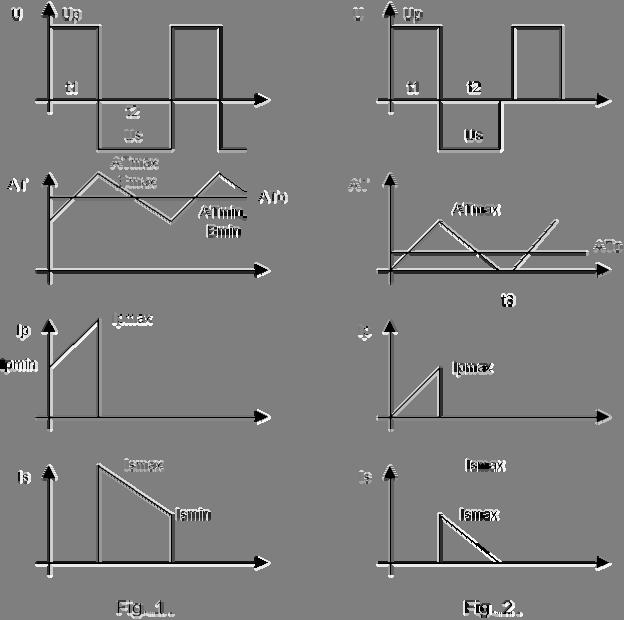
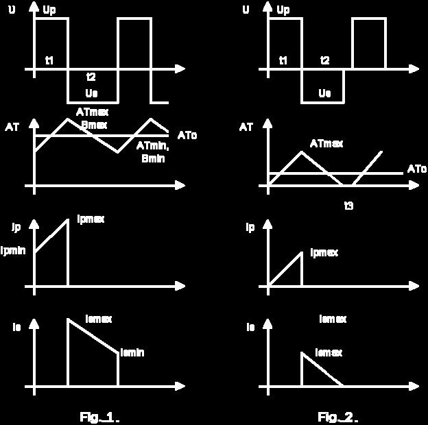
3 With a flyback transformer, the distinction is drawn between two modes of operation: Mode with continuous secondary current ( Fig. 1, t3=0). Mode with intermittent DC secondary current (Fig. 2, t3>0). Continuous mode (Fig.1) In this mode, secondary current ripple is less than 100%: 3 Ripple = 100* (Ismax-Ismin)/(Ismax+Ismin) =(Bmax-Bmin)/(Bmax+Bmin) < 100 In the flyback transformer s continuous mode, the output voltage is "impressed" for practical purposes, and is not greatly dependent upon load. Because the variation of the duty cycle is not directly proportional to the variation of the input voltage, this mode is preferred for a wide range of the input voltages (min. 3:1). Secondly, the flyback transformer is larger with less ripple in the primary current. For that reason, the choice of ripple (10% to 100%) of the secondary current has to be harmonized between the transformer manufacturer and the electronics engineer. Intermittent mode (Fig.2) If the range of the input is not too wide (max. 3:1) then this is the most common operation mode because the flyback transformer is smaller than in the continuous operation mode: t1=t2 at minimal input voltage Ripple => 100%. Input only relevant to the design of a flyback Criterion for design Normally, high-frequency transformers have very low regulation and are designed according to the prescribed temperature rise. Since these transformers are manufactured almost exclusively using ferrite, the optimum operating temperature is around 100 C. Bobbin In order to protect the transistors, high-frequency transformers should be manufactured for low leaking reactance, with single-section bobbin units. For this reason, they often require bifilar or interleaved windings. Ferrite, Induction and Temperature rise Since the optimum operating temperature of ferrite for high-frequency transformers is around 100 C and their ambient temperature is 40 C, our design assumption must be for a temperature rise of 60 K. The program calculates both the active and the reactive core losses by hypothesizing the ferrite type, the frequency, the form of input voltage, induction and core temperature. The induction should be selected so that the transformer does not saturate at minimum input voltage, maximum duty cycle and maximum core temperature. If the core losses in relation to temperature rise are not economically acceptable, then the computer program will optimize or reduce the AC-


4 component (the ripple of the input current) of the induction automatically. But this indicates that the selected ferrite quality is not optimal. Copper additional losses With a high-frequency transformer, the distinctions are drawn between the following additional losses in a winding, over and above the dc-current losses: 1. Eddy current losses 2. Skin effect losses 3. Proximity effect losses 4. Losses due to circulating currents through the parallel-connected wires. Proximity losses are smaller in the case of a winding that takes up only 30-60% of the available winding space. For that reason, one should always set the input for the Space between 0.3 and 0.6 for purposes of automatic core selection by the program. The input for Rac/Rdc will limit the extent of additional losses. The computer program selects a high enough number of parallel-connected wires for the eddy current losses and skin effect losses to fall short of the prescribed value for Rac/Rdc. For that reason, the input for Rac/Rdc is also used for monitoring parallel-connected wires. The value is normally set between 1.25 and 3. Losses of circulating currents through the parallel-connected wires are not calculated. It is assumed that these additional losses have been eliminated by suitable design precautions. In particular, it should be ensured, for a given litz, that the twisting for the winding maintains the same position at the input and at the output of the winding for any given winding. Duty cycle at minimal input voltage 4
1/2 = (125*700) 1/2= 296V. At this input voltage the duty cycle q nom will be 0.5. This flyback transformer has to be designed at the input voltage Upmin = 125V.")
 = 296/(700+296) = 0.")
5 The duty cycle q is defined as follows: A flyback transformer with an automatic controller of output voltage and current ripple less than 100% is normally designed with the following parameters: "Nominal" input voltage Upnom= (Upmin*Upmax)1/2 = (125*700) 1/2= 296V. At this input voltage the duty cycle q nom will be 0.5. This flyback transformer has to be designed at the input voltage Upmin = 125V. At this input voltage the duty cycle will be: q max = Unom/(Umin + Unom) = 296/( ) = 0.7. Th duty cycle at the input voltage Upmax = 700V will be: q min = Upnom/(Upmax+Upnom) = 296/( ) = 0.3 Ripple of the input current at the minimal input voltage = 17% In order to have the ripple smaller than 100% at the maximal input voltage, you have to prescribe the ripple at the minimal input voltage as follows: Ripple min = Ripple max *(Upmin*q max /Upmax/q min )^2 = 100*(0.7*125/750/0.3)^2 < 17% 5
6 Procedure to design a 200W flyback transformer Normally the user loads the standard input file for the flyback transformer and fills in the input mask in accordance with the discussion above. Note that all other parameters (such as chassis, insulation, case, impregnation, ) are generally relevant to the transformer design and will not be discussed: Input voltage : U(V) = 125V Duty cycle : Formfactor = 0.7 Ripple of the primary current (induction) : di/io = 17% Output DC-voltage : Voltage = 2 x 24V Output DC-current ; Current = 2 x 4A Ambient temperature : Amb. Temp. = 40 C Temperature rise : Temp. rise = 60 K Induction = 0.275T 6


7 Single-section bobbin with the primary between 2 secondary : Bobbin = 11 Max. Build 50%: Space = 0.5 Factor for additional Cu-losses : Rac/Rdc = 3 If the core size is not prescribed by the user the input field Selection is set at 0. This means that the program should search for a suitable core for this application from your selected core family. In the system for automatic selection of the core from your prescribed core family, the program will offer you an adequately sized core for your application. On completion of the design work, the following design data will be available, which 7
8 can be saved and/or printed on 3 pages: 8
9 9
10 Checking the design However, there are two parameters, which relate exclusively to the flyback transformer: primary winding inductance (1.12 mh) and the gap (2x0.014") for calibration of the primary winding inductance at the nominal frequency. The winding filling factor :44%<100% 10
. The foil width should be matched to the width of the bobbin.")
")
11 The maximum temperature of the windings is 40 C+57 K = 97 C < 115 C. The number of parallel-connected wires (litz) for the secondary only is 30 x WG 29. A copper foil can replace this litz. The foil thickness should correspond to the wire diameter of the litz (11.3 mill or less). The foil width should be matched to the width of the bobbin. The number of foils connected in parallel is determined in accordance with the following illustration. Using the Test Mode If the design data is not satisfactory, then you can access the test mode, modify the designed transformer manually (turns, wire size, steel, input voltage, load, duty cycle, ) and redesign the transformer by that means. The following output mask in the test mode shows the results by checking the output voltage for the maximal input voltage of 700V and the duty cycle of 0.3: Uin = 700/125 =
 was changed in order to get the nominal input voltage that a voltage controller would give. Ui V Iprms A 2xIsrms A 2xUodc V 2xIodc A Pcu W Pfe W Q Ripple % DTcu K 125 1.")
12 The following table shows the summary of the most important parameters, calculated by the program in the test mode. Note that the duty cycle (q) was changed in order to get the nominal input voltage that a voltage controller would give. Ui V Iprms A 2xIsrms A 2xUodc V 2xIodc A Pcu W Pfe W Q Ripple % DTcu K In order to get the constant total losses in the whole range of the input voltage, select the ferrite and the operation frequency at the nominal input voltage so that you get approximately Pfe = Pcu Technical specification common for all designs All flyback transformers in the following table were calculated under the same conditions: Input voltage : 125Vdc - 700Vdc Output voltages : 2 x 24Vdc Frequency : 100kHz Duty cycle : 0.7 at the input voltage 125V Ripple of the induction : 17% at the input voltage 125Vdc Peak induction : T Build of the windings : approx. 50% 12
13 Ambient temperature : 40 C Temperature rise : 60 K Core family and ferrite : ETD, N27 or better Order of the windings : Primary between both secondary The parameters of the designs are core size, output power and eddy current losses (Rac/Rdc) / Primary Secondary Core Rac/Rdc Power W Inductance mh Turns Parallel x Wire Gauge Turns Parallel x Wire Gauge ETD x37 2x5 1x29 ETD x33 2x16 1x x33 10x34 ETD x30 2x12 1x x29 9x x32 40x36 ETD x28 2x10 30x x33 65x36 ETD39 2, x25 2x8 22x x29 50x x33 140x33 ETD x29 2x6 90x x34 300x38 ETD x30 2x5 200x x36 750x40 13
14 About Designing of Flyback Transformers About Rale Input In order to design a flyback transformer with the Rale Design Software you need the following inputs: 1. Min. input voltage and the duty cycle at this voltage 2. Dc-output voltages and dc-output currents 3. The ripple of the input current (induction) 4. Frequency In the following Figure are 2 typical operation modes: Continuous mod Bmin>0 Discontinuous mode Bmin=0 14
15 User Input Some of customers use other inputs for designing of a flyback. Here are some typical cases Inductance of the primary winding You know: 1. Min. input voltage and the duty cycle at this voltage 2. DC-output voltages and dc-output currents (output power) 3. Inductance of the primary winding 4. Frequency Then you need to calculate the ripple of the primary Pout = L x (Imax^2-Imin^2) x f / 2 = L x (Imax+Imin) x (Imax-Imin) x f /2 Where: Using: Pout Output power in W L Inductance in H F Frequency in Hz Imax Max. primary current (peak) Imin Min. primary current Ripple%= 100 x (Imax-Imin)/(Imax+Imin) Iav = (Imax+Imin)/2 Pout = Uin x Iav x q We can calculate: Pout = 2 x L x Iav^2 x (Ripple%/100) x f or Ripple% = 100 x Uin^2 x q^2 / L / Pout / f / 2 (<=100) Formfactor = 1 / 2 / q Where: Uin Min. input voltage q Duty cycle of the primary Ripple% Ripple of the primary current dio/i = 100 x (Imax-Imin)/(Imax+Imin) 15
16 Ration of the primary and secondary turns in continuous operation mode You know: 1. Min. input voltage 2. DC-output voltages and dc-output currents (output power) 3. Inductance of the primary winding 4. Frequency 5. Ratio of the primary and secondary turns (T1/T2) 6. Continuous operation mode (s=p, Bmin>0, see Figure) Now you need to calculate the duty cycle (Formfactor) and the input dio/i: (Uin x q) / (Uout x s) = (T1/T2) s= p = 1 - q q = A/(1+A) and Formfactor = 1 / 2 / q Ripple% = 100 x Uin^2 x q^2 / L / Pout / f / 2 (<=100) Where: A = (Uout/Uin) x (T1/T2 Ration of the primary and secondary turns in discontinuous operation mode You know: 7. Min. input voltage 8. DC-output voltages and dc-output currents (output power) 9. Inductance of the primary winding 10. Frequency 11. Ratio of the primary and secondary turns (T1/T2) 12. Discontinuous operation mode (s<p, Bmin=0, see Figure) Now you need to calculate the duty cycle (Formfactor) and the input dio/i: The ripple of the primary current is 100% and the primary duty cycle can be calculated: Ripple% = 100 x Uin^2 x q^2 / L / Pout / f / 2 (<=100) and q = (2 x L x Pout x f)^0.5 / Uin (q has to be <1) s = q x (Uin/Uout) / (T1/T2) (s <= 1 - q) and 16
17 dio/i = 100 x (1- q) / s Formfactor = 1 / 2 / q Home 17
How should one design a 250kHz, 120W forward transformer with voltage controller, for input voltage range 200V to 350V, as per IEC 61558?
 How should one design a 250kHz, 120W forward transformer with voltage controller, for input voltage range 200V to 350V, as per IEC 61558? Technical specification relevant only to design Electrical data
How should one design a 50kHz, 1200VA transformer as per IEC 61558?
 How should one design a 50kHz, 1200VA transformer as per IEC 61558? Technical specification relevant only to design Electrical data and diagram Input voltages Frequency Nominal output voltage 1 Nominal
Technical specification relevant only to design. Electrical data and diagram. Frequency. Nominal output voltage. Nominal output current
 How do we design a 60VA - non-inherently short-circuit proof safety transformer for halogen lamps in accordance with IEC 61558, protected by a thermal cutout? Technical specification relevant only to design
Topic 4 Practical Magnetic Design: Inductors and Coupled Inductors
 Topic 4 Practical Magnetic Design: Inductors and Coupled Inductors Louis Diana Agenda Theory of operation and design equations Design flow diagram discussion Inductance calculations Ampere s law for magnetizing
DESIGN AND TECHNOLOGY OF THE MAINS SINGLE PHASE, LOW POWER TRANSFORMER
 ANNEX A6* DESIGN AND TECHNOLOGY OF THE MAINS SINGLE PHASE, LOW POWER TRANSFORMER A6.1 Generalities This presentation aims to help in knowing the constructive structure, the manufacturing technology, as
R. W. Erickson. Department of Electrical, Computer, and Energy Engineering University of Colorado, Boulder
 R. W. Erickson Department of Electrical, Computer, and Energy Engineering University of Colorado, Boulder 13.2.3 Leakage inductances + v 1 (t) i 1 (t) Φ l1 Φ M Φ l2 i 2 (t) + v 2 (t) Φ l1 Φ l2 i 1 (t)
Magnetics Design. Specification, Performance and Economics
 Magnetics Design Specification, Performance and Economics W H I T E P A P E R MAGNETICS DESIGN SPECIFICATION, PERFORMANCE AND ECONOMICS By Paul Castillo Applications Engineer Datatronics Introduction The
Designers Series XIII
 Designers Series XIII 1 We have had many requests over the last few years to cover magnetics design in our magazine. It is a topic that we focus on for two full days in our design workshops, and it has
Designing a 50W Forward Converter Transformer With Magnetics Designer
 Tel. (310) 329-3295 FAX (310) 329-9864 879 W. 190th St., Suite 100 Gardena, CA 90248-4223 Designing a 50W Forward Converter sformer With Magnetics Designer In order to introduce you to the power of Magnetics
Iron Powder Cores for High Q Inductors By: Jim Cox - Micrometals, Inc.
 HOME APPLICATION NOTES Iron Powder Cores for High Q Inductors By: Jim Cox - Micrometals, Inc. SUBJECT: A brief overview will be given of the development of carbonyl iron powders. We will show how the magnetic
Iron Powder Core Selection For RF Power Applications. Jim Cox Micrometals, Inc. Anaheim, CA
 HOME APPLICATION NOTES Iron Powder Core Selection For RF Power Applications Jim Cox Micrometals, Inc. Anaheim, CA Purpose: The purpose of this article is to present new information that will allow the
Glossary of Common Magnetic Terms
 Glossary of Common Magnetic Terms Copyright by Magnelab, Inc. 2009 Air Core A term used when no ferromagnetic core is used to obtain the required magnetic characteristics of a given coil. (see Core) Ampere
Wide ouput range power supply
 Wide ouput range power supply Armond Gauthier Pierre Yves Droz I Introduction I Goal / Constraints of the project Offline power supply. Constraints: - cheap - wide output range application : Power supply
R. W. Erickson. Department of Electrical, Computer, and Energy Engineering University of Colorado, Boulder
 R. W. Erickson Department of Electrical, Computer, and Energy Engineering University of Colorado, Boulder 13.3.2 Low-frequency copper loss DC resistance of wire R = ρ l b A w where A w is the wire bare
Low AC Resistance Foil Cut Inductor
 Low AC Resistance Foil Cut Inductor West Coast Magnetics Weyman Lundquist, Vivien Yang, and Carl Castro West Coast Magnetics Stockton, CA, USA wlundquist@wcmagnetics.com, vyang@wcmagnetics.com, and ccastro@wcmagnetics.com.
Renco Electronics, Inc.
 Abstract The operating frequency of most electronic circuits has been increasing since the late 1950 s. While the increase in frequency has reduced the overall weight and size of most consumer electronics
Transformers for Offline Flyback Converters
 Transformers for Offline Flyback Converters WHITE PAPER ABSTRACT This paper examines the design of a Bourns Model flyback transformer for a low power offline converter which could be used in applications
HP1, HPH1 HP2, HPH2 HP3, HPH3 HP4, HPH4 HP5, HPH5 HP6, HPH6. Winding Layout. Middle 11. Inner
 Document - HP, HPH HP, HPH HP, HPH HP, HPH HP, HPH HP, HPH Six : isolated windings that can be connected in series or parallel Tightly coupled windings Power range: 0 Watts as inductor and flyback transformer;
Magnetics. Selection guide for a coupled inductor used in Sepic DC/DC Converter. Application Note. BI Technologies
 Selection guide for a coupled inductor used in Sepic DC/DC Converter. The most popular DC/DC Converter topology used on the led drivers in automotive industry is SEPIC topology (single ended primary inductance
Basic High Voltage / Horizontal Deflection
 Basic High Voltage / Horizontal Deflection In a monochrome monitor it is common to get the high voltage from the horizontal deflection circuit. The retrace pulse is multiplied by the turn ration of the
Windings for High Frequency
 Windings for High Frequency Charles R. Sullivan chrs@dartmouth.edu Dartmouth Magnetics and Power Electronics Research Group http://power.engineering.dartmouth.edu 1 The Issue The best-available technology
West Coast Magnetics. Advancing Power Electronics FOIL WINDINGS FOR SMPS INDUCTORS AND TRANSFORMERS. Weyman Lundquist, CEO and Engineering Manager
 1 West Coast Magnetics Advancing Power Electronics FOIL WINDINGS FOR SMPS INDUCTORS AND TRANSFORMERS Weyman Lundquist, CEO and Engineering Manager TYPES OF WINDINGS 2 Solid wire Lowest cost Low DC resistance
Transformer and Inductor Design for Optimum Circuit Performance
 Power Supply Design Seminar Transformer and Inductor Design for Optimum Circuit Performance Topic Category: Magnetic Component Design Reproduced from 2002 Texas Instruments Power Supply Design Seminar
Switch Mode Power Supplies and their Magnetics
 Switch Mode Power Supplies and their Magnetics Many factors must be considered by designers when choosing the magnetic components required in today s electronic power supplies In today s day and age the
Telemetrie-Messtechnik Schnorrenberg
 Telemetrie-Messtechnik Schnorrenberg MTP-IND-PWR User Manual Inductive power supply set Power supply for power head 25 and 50mm mounting tape to fix coil on shaft Ferrite tape 30mmx3m CUL 1.00 mm (Enamelled
Flyback transformer design considerations for efficiency and EMI
 Flyback transformer design considerations for efficiency and EMI Isaac Cohen Bernard Keogh Agenda Flyback transformer basics Review of Flyback transformer losses: o Core loss dependence on DC bias, duty
LEAKAGE FLUX CONSIDERATIONS ON KOOL Mµ E CORES
 LEAKAGE FLUX CONSIDERATIONS ON E CORES Michael W. Horgan Senior Applications Engineer Magnetics Division of Spang & Co. Butler, PA 163 Abstract Kool Mu, a Silicon-Aluminum-Iron powder, is a popular soft
Laminate Transformer Testing
 1. Introduction: Laminate transformers are mostly used as line frequency, low frequency and low/high voltage step-up, step-down transformers. Two coils are wound over a core such that they are magnetically
Optimizing Custom Magnetics for High-Performance Power Supplies
 Optimizing Custom Magnetics for High-Performance Power Supplies Michael Seeman, Ph.D. Founder / CEO. mike@eta1power.com April 2018 PELS Seminar 2018. Outline What is Power Supply Optimization? Performance
DESIGN TIPS FOR L6561 POWER FACTOR CORRECTOR
 AN1214 APPLICATION NOTE DESIGN TIPS FOR L6561 POWER FACTOR CORRECTOR IN WIDE RANGE by Cliff Ortmeyer & Claudio Adragna This application note will describe some basic steps to optimize the design of the
The Ins and Outs of Audio Transformers. How to Choose them and How to Use them
 The Ins and Outs of Audio Transformers How to Choose them and How to Use them Steve Hogan Product Development Engineer, Jensen Transformers 1983 1989 Designed new products and provided application assistance
What is an Inductor? Token Electronics Industry Co., Ltd. Version: January 16, Web:
 Version: January 16, 2017 What is an Inductor? Web: www.token.com.tw Email: rfq@token.com.tw Token Electronics Industry Co., Ltd. Taiwan: No.137, Sec. 1, Zhongxing Rd., Wugu District, New Taipei City,
Planar Transformer Prototyping Kit. Designer s Kit C356
 Planar Transformer Prototyping Kit Designer s Kit C Contents Introduction... Kit Contents... Part Details... Core... Primary Boards... Secondary Stamps... Auxiliary Boards... Pins and Insulators... Designing
Switching Frequency and Efficiency: A Complex Relationship
 Switching Frequency and Efficiency: A Complex Relationship By Andrew Smith Senior Product Marketing Manager Power Integrations Power supply designers can increase efficiency while moving to a higher switching
Use of inductive heating for superconducting magnet protection*
 PSFC/JA-11-26 Use of inductive heating for superconducting magnet protection* L. Bromberg, J. V. Minervini, J.H. Schultz, T. Antaya and L. Myatt** MIT Plasma Science and Fusion Center November 4, 2011
HOME APPLICATION NOTES
 HOME APPLICATION NOTES INDUCTOR DESIGNS FOR HIGH FREQUENCIES Powdered Iron "Flux Paths" can Eliminate Eddy Current 'Gap Effect' Winding Losses INTRODUCTION by Bruce Carsten for: MICROMETALS, Inc. There
The Flyback Converter
 The Flyback Converter Course Project Power Electronics Design and Implementation Report by Kamran Ali 13100174 Muhammad Asad Lodhi 13100175 Ovais bin Usman 13100026 Syed Bilal Ali 13100026 Advisor Nauman
Practical Tricks with Transformers. Larry Weinstein K0NA
 Practical Tricks with Transformers Larry Weinstein K0NA Practical Tricks with Transformers Quick review of inductance and magnetics Switching inductive loads How many voltages can we get out of a $10 Home
LM78S40 Switching Voltage Regulator Applications
 LM78S40 Switching Voltage Regulator Applications Contents Introduction Principle of Operation Architecture Analysis Design Inductor Design Transistor and Diode Selection Capacitor Selection EMI Design
Experience the Power of Confidence
 Experience the Power of Confidence the confidence of over fifty years of expertise in the research, design, manufacture and support of high quality magnetic materials and components. A leading manufacturer
Bridgeport Magnetics Design Guide
 Bridgeport Magnetics Design Guide Our design guide takes you step by step through the process of designing a toroidal transformer. No engineering design charges for all standard designs. State of the art
Improved High-Frequency Planar Transformer for Line Level Control (LLC) Resonant Converters
 Resonant Converters") Improved High-Frequency Planar Transformer for Line Level Control (LLC) Resonant Converters Author Water, Wayne, Lu, Junwei Published 2013 Journal Title IEEE Magnetics Letters DOI https://doi.org/10.1109/lmag.2013.2284767
Improved High-Frequency Planar Transformer for Line Level Control (LLC) Resonant Converters Author Water, Wayne, Lu, Junwei Published 2013 Journal Title IEEE Magnetics Letters DOI https://doi.org/10.1109/lmag.2013.2284767
DUAL STEPPER MOTOR DRIVER
 DUAL STEPPER MOTOR DRIVER GENERAL DESCRIPTION The is a switch-mode (chopper), constant-current driver with two channels: one for each winding of a two-phase stepper motor. is equipped with a Disable input
CITY UNIVERSITY OF HONG KONG
 CITY UNIVERSITY OF HONG KONG Modeling and Analysis of the Planar Spiral Inductor Including the Effect of Magnetic-Conductive Electromagnetic Shields Submitted to Department of Electronic Engineering in
Lecture 6 ECEN 4517/5517
 Lecture 6 ECEN 4517/5517 Experiment 4: inverter system Battery 12 VDC HVDC: 120-200 VDC DC-DC converter Isolated flyback DC-AC inverter H-bridge v ac AC load 120 Vrms 60 Hz d d Feedback controller V ref
Shielded Power Inductors
 Shielded Power Inductors MN509 Shielded inductor with minimum EMI Minimum power loss Non standard values available Low DC resistance Flat top for SMT operations Specifications Inductance tested at 100KHz
Ferrite Transformer Testing
 AT Series Testers Application Note Ferrite Transformer Testing VPN: 104-128/2 Voltech Instruments, all rights reserved Page 1 of 16 Introduction: As electronic products utilise higher frequency techniques
Large Kool Mµ Core Shapes
 Large Kool Mµ Core Shapes TECHNICAL BULLETIN Ideal for high current inductors, large Kool Mµ geometries (E cores, U Cores and Blocks) offer all the advantages of Kool Mµ material, low core loss, excellent
800 W PFC evaluation board
 800 W PFC evaluation board EVAL_800W_PFC_C7_V2 / SP001647120 / SA001647124 High power density 800 W 130 khz platinum server design with analog & digital control Garcia Rafael (IFAT PMM ACDC AE) Zechner
Outcomes from this session
 Outcomes from this session At the end of this session you should be able to Understand what is meant by the term losses. Iron Losses There are three types of iron losses Eddy current losses Hysteresis
ELEC4240/ELEC9240 POWER ELECTRONICS
 THE UNIVERSITY OF NEW SOUTH WALES FINAL EXAMINATION JUNE/JULY, 2003 ELEC4240/ELEC9240 POWER ELECTRONICS 1. Time allowed: 3 (three) hours 2. This paper has six questions. Answer any four. 3. All questions
Differential-Mode Emissions
 Differential-Mode Emissions In Fig. 13-5, the primary purpose of the capacitor C F, however, is to filter the full-wave rectified ac line voltage. The filter capacitor is therefore a large-value, high-voltage
Inductors & Resonance
 Inductors & Resonance The Inductor This figure shows a conductor carrying a current. A magnetic field is set up around the conductor as concentric circles. If a coil of wire has a current flowing through
Large Kool Mµ Core Shapes
 Large Kool Mµ Core Shapes TECHNICAL BULLETIN Ideal for high current inductors, large Kool Mµ geometries (E cores, U Cores and Blocks) offer all the advantages of Kool Mµ material, low core loss, excellent
The Reliable Source... FERROPERM. Inductors. Transformers
 The Reliable Source... FERROPERM for High Quality Inductors and Transformers INDUCTORS AND TRANSFORMERS from FERROPERM UK Ltd. FERROPERM offers a manufacturing capability for the production of most types
Lecture 16 Transformer Design
 Design and Simulation of DC-DC converters using open source tools Prof. L. Umanand Department of Electronics System Engineering Indian Institute of Science, Bangalore Lecture 16 Transformer Design In this
Impact of Fringing Effects on the Design of DC-DC Converters
 Impact of Fringing Effects on the Design of DC-DC Converters Michael Seeman, Ph.D. Founder / CEO. 2018 APEC PSMA/PELS 2018. Outline Fringe-field loss: What does a power supply designer need to know? Which
Switching Power Supplies
 Switching Power Supplies Chuck Clark AF8Z WWW..ORG 1 Regulated Power Supply Basics WWW..ORG 2 Topics Linear Supplies Switching Supplies Components WWW..ORG 3 Why switching supplies Smaller Lighter More
SHARDA Make Harmonics Filter
 SHARDA Make Harmonics Filter SHARDA offers perfect solution to minimize Harmonics level of industries where non-linear load like, VFD, Electronics load, Convertors, Voltage booster equipment s are present.
Achieving Higher Efficiency Using Planar Flyback Transformers for High Voltage AC/DC Converters
 Achieving Higher Efficiency Using Planar Flyback Transformers for High Voltage AC/DC Converters INTRODUCTION WHITE PAPER The emphasis on improving industrial power supply efficiencies is both environmentally
Leakage Flux Recovery Coil for Energy Harvesting Using Magnetoplated Wire
 APSAEM14 Jorunal of the Japan Society of Applied Electromagnetics and Mechanics Vol.3, No.3 (15) Regular Paper Leakage Flux Recovery Coil for Energy Harvesting Using Magnetoplated Wire Tatsuya YAMAMOTO
AN1606 APPLICATION NOTE A BRIDGELESS P.F.C. CONFIGURATION BASED ON L4981 P.F.C. CONTROLLER.
 AN1606 APPLICATION NOTE A BRIDGELESS P.F.C. CONFIGURATION BASED ON L4981 P.F.C. CONTROLLER. by Ugo Moriconi This technical document describes an innovative topology dedicated to a medium to high power
Fundamentals of Power Electronics
 Fundamentals of Power Electronics SECOND EDITION Robert W. Erickson Dragan Maksimovic University of Colorado Boulder, Colorado Preface 1 Introduction 1 1.1 Introduction to Power Processing 1 1.2 Several
TUTORIAL Inductor Loss Calculation in Thermal Module
 TUTORIAL Inductor Loss Calculation in Thermal Module October 2016 1 The Thermal Module provides the capability to calculate the winding losses, core losses, and temperature rise of inductors based on standard
Target Temperature Effect on Eddy-Current Displacement Sensing
 Target Temperature Effect on Eddy-Current Displacement Sensing Darko Vyroubal Karlovac University of Applied Sciences Karlovac, Croatia, darko.vyroubal@vuka.hr Igor Lacković Faculty of Electrical Engineering
Selecting the Best Inductor for Your DC-DC Converter Leonard Crane Coilcraft
 Selecting the Best Inductor for Your DC-DC Converter Leonard Crane Coilcraft Understanding the Data Sheet Abstract Proper inductor selection requires a good understanding of inductor performance and of
Wire Wound Chip Inductors LPI0805FT Series
 INTRODUCTION Product : LPI Miniature SMD Inductor For Power Line Size : 0805 The LPI series are low profile inductor used in notebook, PC, cellular phone backlight, inverter and etc. The devices are designed
MICROCONTROLLER BASED BOOST PID MUNAJAH BINTI MOHD RUBAEE
 MICROCONTROLLER BASED BOOST PID MUNAJAH BINTI MOHD RUBAEE This thesis is submitted as partial fulfillment of the requirement for the award of Bachelor of Electrical Engineering (Power System) Faculty of
SMA MAGNETICS. Efficient solutions for electrotechnical sector
 SMA MAGNETICS Efficient solutions for electrotechnical sector About us Mission SMA Magnetics Sp. z o.o. is the magnetic components manufacturer that operates in field of electrical engineering in area
ECONO-PAC /OCTA-PAC OCTA-PAC PLUS Power Inductors and Transformers
 Description Surface mount magnetics that can be used as single or coupled inductors or 1:1 transformers that provide isolation between two windings OCTA-PAC s are designed around high frequency, low loss
Application Note. Application for Precision Impedance Meters in a Standards Laboratory. Required Capabilities for Precision Measurements
 Application for Precision Impedance Meters in a Standards Laboratory The IET Labs 1689 Precision RLC Digibridge, which measures resistance, capacitance and inductance, has found wide acceptance in production
COMPLIANT Common Mode Chokes - UU9.8 & UU10.5 Series
 Document FR00 COMPLIANT Common Mode Chokes - UU9.8 & UU0.5 Series Order Code MCU 000 MCU 0002 Core Mounting Inductance mh (Min) UU9.8 Series Current Rating ma (steady state) 350 350 Leakage DC Inductance
Inductor Glossary. Token Electronics Industry Co., Ltd. Version: January 16, Web:
 Version: January 16, 2017 Inductor Glossary Web: www.token.com.tw Email: rfq@token.com.tw Token Electronics Industry Co., Ltd. Taiwan: No.137, Sec. 1, Zhongxing Rd., Wugu District, New Taipei City, Taiwan,
The Future for SMPS Magnetics
 The Future for SMPS Magnetics Weyman Lundquist President and CEO West Coast Magnetics ISO9001:2008 ISO13485 Registered How Much Smaller Can SMPS Power Magnetics Get? How Quickly? How much can we reduce
MIC2171. General Description. Features. Applications. Typical Application. 100kHz 2.5A Switching Regulator
 1kHz.5A Switching Regulator General Description The is a complete 1kHz SMPS current-mode controller with an internal 65.5A power switch. Although primarily intended for voltage step-up applications, the
Large Kool Mµ Core Shapes
 Large Kool Mµ Core Shapes Technical Bulletin Ideal for high current inductors, large Kool Mµ geometries (E cores, Toroids, U Cores and Blocks) offer all the advantages of Kool Mµ material, low core loss,
AT2596 3A Step Down Voltage Switching Regulators
 FEATURES Standard PSOP-8/TO-220-5L /TO-263-5L Package Adjustable Output Versions Adjustable Version Output Voltage Range 1.23V to 37V V OUT Accuracy is to ± 3% Under Specified Input Voltage the Output
An Interleaved Flyback Inverter for Residential Photovoltaic Applications
 An Interleaved Flyback Inverter for Residential Photovoltaic Applications Bunyamin Tamyurek and Bilgehan Kirimer ESKISEHIR OSMANGAZI UNIVERSITY Electrical and Electronics Engineering Department Eskisehir,
DC-to-DC Converter for Low Voltage Solar Applications
 Proceedings of the th WSEAS International Conference on CIRCUITS, Agios Nikolaos, Crete Island, Greece, July 3-, 7 4 DC-to-DC Converter for Low Voltage Solar Applications K. H. EDELMOSER, H. ERTL Institute
Conventional Single-Switch Forward Converter Design
 Maxim > Design Support > Technical Documents > Application Notes > Amplifier and Comparator Circuits > APP 3983 Maxim > Design Support > Technical Documents > Application Notes > Power-Supply Circuits
7.2 SEPIC Buck-Boost Converters
 Boost-Buck Converter 131 5. The length of the trace from GATE output of the HV9930 to the GATE of the MOSFET should be as small as possible, with the source of the MOSFET and the GND of the HV9930 being
Realisation of the galvanic isolation in customer-end DC to AC inverters for the LVDC distribution
 Realisation of the galvanic isolation in customer-end DC to AC inverters for the LVDC distribution Background: The electric distribution network in Finland has normally voltage levels of 20 kv and 400
LLC Resonance Power Transformers Using Magnetoplated Wire. and Shigeaki Tsuchiya b,
 LLC Resonance Power Transformers Using Magnetoplated Wire Yinggang Bu a, *, Masahiro Nishiyama a, Tatsuya Yamamoto a, Tsutomu Mizuno a and Shigeaki Tsuchiya b, a Faculty of Engineering, Shinshu University,
SMALLER-FASTER- OW R CO$T
 SMALLER-FASTER- OW R CO$T Magnetic Materials for Today s High-Power Fast-Paced Designs Donna Kepcia Technical Sales Manager Magnetics DISCUSSION OVERVIEW Semiconductor Materials, SiC, Silicon Carbide &
HIGH FREQQUENCY TRANSFORMER DESIGN PROGRAM MANUAL V12.0
 HITRIN OPTIMIZED PROGRAM SERVICE, LLC Electro-Magnetic Design Using Advanced Computer Techniques HIGH FREQQUENCY TRANSFORMER DESIGN PROGRAM MANUAL V12.0 www.opsprograms.com opseast@opsprograms.com HITRIN
TL-W. Standard Flat Inductive Proximity Sensors. Ordering Information. Front and side facing surface IP67 DC 2-wire and DC 3-wire models
 Standard Flat Inductive Proximity Sensors Front and side facing surface IP67 DC -wire and DC -wire models Ordering Information DC -wire Models Shape distance Model Output and operating status mm MD1 *1
discontinued October 31, 2017 or until inventory is
 Supersedes June 2017 Applications Computer and portable power devices LCD panels, DVD players Inductor: DC-DC converters Buck, boost, forward, and resonant converters Noise filtering and filter chokes
Walchand Institute of Technology. Basic Electrical and Electronics Engineering. Transformer
 Walchand Institute of Technology Basic Electrical and Electronics Engineering Transformer 1. What is transformer? explain working principle of transformer. Electrical power transformer is a static device
Medium Power 137kHz Linear Power Amplifier G4JNT Sept 2010
 Medium Power 137kHz Linear Power Amplifier G4JNT Sept 2010 This project was conceived on the back of an envelope after running a WSPR beacon thorough my 600 Watt switch mode Power Amplifier, and setting
TOPSwitch for Telecom and
 DC to DC Converters Using TOPSwitch for Telecom and Cablecom pplications Design Note DN-6 Description The TOPSwitch product family provides a cost effective and reliable solution for DC to DC converter
SOME STUDIES ON HIGH FREQUENCY RESONANT INVERTER BASED INDUCTION HEATER AND THE CORRESPONDING CHOICE OF SECONDARY METALLIC OBJECTS
 SOME STUDIES ON HIGH FREQUENCY RESONANT INVERTER BASED INDUCTION HEATER AND THE CORRESPONDING CHOICE OF SECONDARY METALLIC OBJECTS ATANU BANDYOPADHYAY Reg.No-2010DR0139, dt-09.11.2010 Synopsis of Thesis
Volts Volts. Pout < 4.0W (See Fig 8/9) Pout < 11.5W (See Fig 8/9) EnablePin Threshold uamps In to/out of enable pin: Venable = 0-16V
 Pout < 11.5W (See Fig 8/9) EnablePin Threshold uamps In to/out of enable pin: Venable = 0-16V") Specifications: 363/36 Rev: G Description: The 363/36 series high voltage power supplies are miniature flyback boost converters operating from 2 to 6VDC input, with an output of 50 to 200VDC set by a single
Specifications: 363/36 Rev: G Description: The 363/36 series high voltage power supplies are miniature flyback boost converters operating from 2 to 6VDC input, with an output of 50 to 200VDC set by a single
By Hiroo Sekiya, Chiba University, Chiba, Japan and Marian K. Kazimierzuk, Wright State University, Dayton, OH
 ISSUE: November 2011 Core Geometry Coefficient For Resonant Inductors* By Hiroo Sekiya, Chiba University, Chiba, Japan and Marian K. Kazimierzuk, Wright State University, Dayton, OH A resonant inductor
COMPONENTS MODULES CORES
 COMPONENTS MODULES CORES 211 SUMIDA Components & Modules GmbH Dr. Hans-Vogt-Platz 1 D-9413 Obernzell Phone: ++49/85 91/937- Fax: ++49/85 91/937-3 E-Mail: contact@sumida-eu.com Internet: www.sumida-eu.com
Common Mode Filter Inductor Analysis
 Document 2-1 Common Mode Filter Inductor Analysis Abstract Noise limits set by regulatory agencies make solutions to common mode EMI a necessary consideration in the manufacture and use of electronic equipment.
Reference Design EBC iw for 12V 600mA Network Adapter Design
 Reference Design EBC10011 iw1706-00 for 12V 600mA Network Adapter Design Table of Contents iw1706-00 For Network Adapter Design (AC Input 90 264V AC, Output 12V 600mA) EBC10011 1.0. Introduction...3 2.0.
TRAFTOR WINDINGS CHANGING THE RULES TOROIDAL INDUCTORS & TRANSFORMERS SOLUTIONS PROVIDER AND MANUFACTURER
 TRAFTOR WINDINGS CHANGING THE RULES TOROIDAL INDUCTORS & TRANSFORMERS SOLUTIONS PROVIDER AND MANUFACTURER PRODUCT RANGE POWER INDUCTORS Toroidal technology, driven by 20 years of R&D. POWER TRANSFORMERS
Finite Element Analysis (FEA) software. Magnetic component design. 3D Electromagnetic Simulation Allows Reduction of AC Copper Losses
 software. Magnetic component design. 3D Electromagnetic Simulation Allows Reduction of AC Copper Losses") ABSTRACT AC currents in multiple layers in the transformer window can increase copper losses significantly due to the proximity effect. Traditionally used Dowell s curves show that the phenomenon starts
ABSTRACT AC currents in multiple layers in the transformer window can increase copper losses significantly due to the proximity effect. Traditionally used Dowell s curves show that the phenomenon starts
IEC Standard Caledonian Offshore & Marine Cables
 Power Copper s According to IEC 60228 Tinned conductors Cross section cl.2 cl.5 Cross section cl.2 cl.5 mm² Ohm/km Ohm/km mm² Ohm/km Ohm/km 1.0 18.2 20 70 0.270 0.277 1.5 12.2 13.7 95 0.195 0.210 2.5 7.56
Dry Type Distribution Transformers NON-LINEAR TRANSFORMER PRESENTATION
 NON-LINEAR TRANSFORMER PRESENTATION 1 PROBLEM: HARMONICS CAUSE EXCESSIVE TRANSFORMER HEATING Increased Losses Proximity Skin Effect Stray Losses Circulating Effect Triplen Harmonics Add in Neutral Increased