How should one design a 250kHz, 120W forward transformer with voltage controller, for input voltage range 200V to 350V, as per IEC 61558?
|
|
|
- Phyllis Mason
- 5 years ago
- Views:
Transcription
1 How should one design a 250kHz, 120W forward transformer with voltage controller, for input voltage range 200V to 350V, as per IEC 61558? Technical specification relevant only to design Electrical data and diagram: Input voltages range Frequency Nominal output voltage Nominal output current Ripple of the input current 200Vdc - 350Vdc (bridge rectifier with RCload, for input voltage 230Vac+10%-20%, 50Hz) 70kHz 2 x 12Vdc, automatic controlled on the primary side 2 x 5Adc, -50% Max. 50% at the maximal input voltage and the nominal load Ambient and operating conditions: Ambient temperature 40 C Test conditions Mode of operation Non inherently short-circuit proof Continuous Specification Insulation class E The following forward transformer diagram illustrates only parameters relating to design. The windings for rekuperation and for measurement cannot be calculated by program. 1


2 During the initial half period a normal AC transformer is powered by positive voltage, and during the second half period by negative voltage. The values of the voltagetime surfaces of both voltages are the same. This changes the induction in the core of the AC transformer from -Bmax to +Bmax. In the case of a forward transformer, the start of the primary development Wp during the initial switching period q*t, which is not necessarily the same as the second switching period, is fed to the input voltage Up. In this time the induction rises from Br to Bmax. During the second switching period the end of the recuperation development Wr is fed to the same input voltage. In this time the induction falls from Bmax to Br. In this frequently-used forward transformer switch, magnetic energy stored during the switch-on phase q*t is returned to the feed source via the feed source recuperation development Wr. There are several layouts which can be used to realize the recuperation. For this reason, and because the structural performance of this winding is normally only approx. 10%-20% of the structural performance of the winding Wp, this winding is not calculated with the program. The user calculates it manually. 2


3 In the case of forward transformers, one distinguishes between 2 main phases during a switching period: during the first phase the primary voltage Up is fed to the primary winding Wp. The primary voltage increases in direct proportion to the voltage IL through the choke L. In addition comes the magnetizing voltage io. The voltage lies in the secondary winding: 3 Us = (Uo+Udiode) / q. During the second phase the primary winding WP is separated from the primary voltage. The magnetic energy which is stored in this is returned via the winding Wr. The number of windings Wr in this winding is chosen to ensure that the conditions: q + r < and r = q * (Wr/Wp) are constantly fulfilled. The relative switch-on duration q is chosen to be between 0.40 and 0.60 at minimum input voltage. This produces:
4 r < or Wr = ( ) * Wp During the switching period T, the induction changes by pulsing between Br and Bmax. The choice of Bmax depends on the ferrite type and on the operating temperature. The residual induction Br can be set practically at a value between 5% and 10% of the Bmax induction by an air gap in the core. With an external source or a permanent magnet it would be possible to set a negative residual induction. The ripple of the voltage through the choke L affects the effective value of the transformer voltage. This value must be notified by the user. Criteria for design Ripple = 100 * (Ilmax-Ilmin)/Ilmax+Ilmin) IEC A high-frequency transformer with non- inherently short-circuit proof as per IEC is equipped with a safety. Very often we arrive at a combined protection solution consisting of a thermal cutout in the transformer and cutout electronics in the cycled mains power unit to protect against overload and short-circuit. For this reason, short-circuit and overloads are not design criteria. The criterion for design with regard to IEC is only temperature θ nominal. Insulation class A E B F H Max winding temperature in nominal operating mode θ nominal ( C) Insulation class Max winding temperature in nominal operating mode = 115 C Insulation class E is prescribed. Criterion for design Normally, high-frequency transformers have very low regulation and are designed according to the prescribed temperature rise. Since these transformers are manufactured almost exclusively using ferrites, the optimum operating temperature is around 100 C. 4
5 Bobbin unit In order to protect the transistors, high-frequency transformers should be manufactured for low leaking reactance, with single-chamber bobbin units. For this reason, we very often arrive at bifilar or interleaved windings. Ferrite quality Since the optimum operating temperature of ferrite for high-frequency transformers over 100VA is around 100 C and their ambient temperature is between 40 C and 70 C, our design assumption must be for a temperature rise of between 30 K and 60 K. If the core losses in relation to temperature rise are not economically acceptable, then the computer program will optimize or reduce the AC-component of the induction automatically. But this does indicate that the selected ferrite quality is not optimized. Induction and ferrite quality High-frequency transformers are equipped almost exclusively with ferrites. The program calculates both the active and the reactive core losses by hypothesizing the ferrite type, the frequency, the form of input voltage, induction and core temperature. The induction should be selected such that the transformer does not saturate at maximum input voltage and maximum core temperature. Copper additional losses With a high-frequency transformer, the distinctions are drawn between the following additional losses in a winding, over and above the dc-current losses: 1. Eddy current losses 1. Displacement losses 1. Proximity effect losses 1. Losses due to circulating currents through the parallel-connected wires. Additional losses are smaller in the case of a winding that takes up only 30-60% of the available winding space. For that reason, one should always set the input for the filling factor between 0.3 and 0.6 for purposes of automatic core selection. The input for Rac/Rdc will limit the extent of additional losses (eddy current losses and displacement losses). The computer program selects a high enough number of parallel-connected wires for the eddy current losses and displacement losses to fall short of the prescribed value for Rac/Rdc. For that reason, the input for Rac/Rdc is also used for monitoring of parallel-connected wires. The value is normally set between 1.5 and 5. Proximity effects can be reduced by means of the Spread input. Another option for reducing proximity effects is to select wires with thicker insulation. Losses of circulating currents through the parallel-connected wires are not calculated. It is assumed that these additional losses have been eliminated by suitable design precautions. In particular, it should be ensured, for a given litz, that the twisting for the winding is done such that a given wire has the same position at the input and at the output of the winding. 5

 A forward transformer with an automatic controller of")

 = 1 Th relative switch-on period at the input voltage Upmax = 350V will be: q min = q max *")
6 Nominal input voltage and relative switch-on period The relative primary voltage switch-on period is defined as follows: In the design of a forward transformer, the duration of the relative switch-on period (q = t1/(t1+t2) ) is taken into account indirectly via the input mode of the form factor: Form factor = 1/(2*q) A forward transformer with an automatic controller of output voltage is normally designed with the following parameters: "Nominal" input voltage Upmin = 200V. At this input voltage the relative switch-on period q max will be 0.5 and the relative recuperation period r min = The form factor = 1/(2* q max ) = 1/(2*0.5) = 1 Th relative switch-on period at the input voltage Upmax = 350V will be: q min = q max * Upmin/Upmax = 0.5 * 200 / 350 =

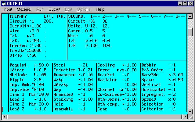
7 Procedure for design 1. If you are not yet acquainted with Rale design software, please read the text "How should I design a small transformer?". Keep a copy of this text within convenient reach whenever performing design work. 2. Fill in the design input mask as follows. If you need any help, press function keys F1. There is extensive description for each input field. 3. The Selection input field is set at 0. This means that the program should search on-line for a suitable core for this application, from your selected core family. 4. Save your input data file. In this specimen design calculation, we saved the input data in input data file CAL0011E.TK1. This input data file was supplied together with this document. Copy it into the directory in which your Rale demo program is installed. 5. Connect up to the Rale design server. 6. Load up your input data file. 7. Now select the core family and the core for automatic search by the computer program. 7


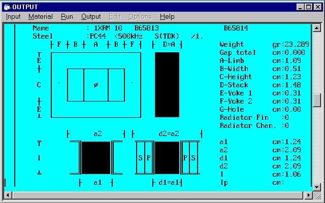
8 8 8. Click on OK. 9. Start your design work. In the system for automatic selection of the core from your prescribed core family, the program will offer you an adequately sized core for your application. Click on OK in order to accept the core. 10. On completion of your design work, the following design data is available. We must not omit to mention at this point that the calculated data for shortcircuit is not applicable to the forward transformer (and cannot be used for that context). 11. On completion of the design work, the following design data will be available, which can be printed on 3 pages.

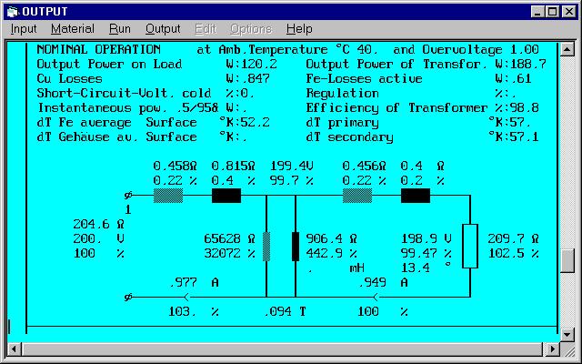
9 9 12.

10 10

11 11


12 13. Checking of the design data follows this. We now check the winding data and the filling factor (34.2%<100%). The maximum temperature of the windings is 40 C+57.1 K = 97.1 C < 115 C. The number of parallel-connected wires with 0.16 mm diameter is 6 and 27. Commercial considerations prompt us to select a litz of 5 wires of 0.16 mm diameter for the primary and a litz of 30 wires of 0.16mm for both secondary windings. This operation must be performed manually in the test mode. There now follows the configuration of the recuperation winding Wr: Wr = Wp * r min /q max = 23 * / 0.5 = 13 windings The number of parallel-switched wires is smaller than the number of parallel-switched wires in the primary winding Wp by the factor Iporms/Iprms. 12
 = 1.754.")
13 5 * 0.218/0.99= 1 wire Iporms => No-load voltage Iprms => Primary nominal voltage 13. This is followed by checking of the output voltage for the maximal input voltage of 350V and the relative switch-on period of 0.285: Uin = 350/200 = 1.75 and form factor = 1/(2*0.285) = Note that the program controls your input in order to avoid the operation in the saturation of the core. If you get any problem with your input, follow these procedures. or Increase the form factor to (q = 0.285) Press F6 to recalculate Increase the input voltage to 350V : Uin = 1.75 Press F6 to recalculate Decrease the input voltage to 200V : Uin = 1 Press F6 to recalculate Decrease the form factor to 1.0 (q = 0.5) Press F6 to recalculate The following table shows the summery of the most important parameters, calculated by program in the test mode. Note that the relative switch-on period (q) was changed in order to get the nominal input voltage as by a voltage controller. 13
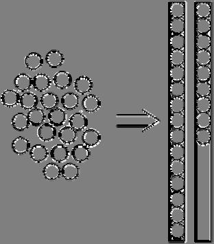
14 Ui V Iprms A 2xIsrms A 2xUodc V 2xIodc A Pcu W Pfe W q Ripple % dtcu K If the design data is not satisfactory, then there are two ways by which we can implement the desired correction: You can return to the input mask (function key F2), correct the input data and redesign the transformer. Or you can access the test program (function key F5), modify the designed transformer manually and redesign the transformer by that means. 12. On completion of the design work, you can print out the design data on-line, or save it on your local PC and print it out off-line. The output data file from this design example, CAL0011E.TK2, is supplied together with this document. Copy it into the directory in which your Rale demo program is installed. Tips & Tricks Rounding off the number of windings With a flyback transformer, the procedure for rounding off the number of windings differs from that employed with a "normal" transformer. Next, we correct the nominal primary voltage until the desired number of primary windings is reached. In the test program, finally, the number of windings is rounded off manually. Copper strip instead of litz A copper strip can replace a litz. The strip thickness should correspond to the wire diameter of the litz. Strip width should be matched to the width of the bobbin. The number of strips connected in parallel is determined in accordance with the following illustration. 14

15 Home 15
How should one design a 50kHz, 1200VA transformer as per IEC 61558?
 How should one design a 50kHz, 1200VA transformer as per IEC 61558? Technical specification relevant only to design Electrical data and diagram Input voltages Frequency Nominal output voltage 1 Nominal
Designing 100kHz, flyback transformers for input voltage vdc and power up to 500W
 In the beginning Designing 100kHz, flyback transformers for input voltage125-700vdc and power up to 500W Thirty years ago, designers calculated transformers on their pocket calculators. The designer had
Technical specification relevant only to design. Electrical data and diagram. Frequency. Nominal output voltage. Nominal output current
 How do we design a 60VA - non-inherently short-circuit proof safety transformer for halogen lamps in accordance with IEC 61558, protected by a thermal cutout? Technical specification relevant only to design
Practical Tricks with Transformers. Larry Weinstein K0NA
 Practical Tricks with Transformers Larry Weinstein K0NA Practical Tricks with Transformers Quick review of inductance and magnetics Switching inductive loads How many voltages can we get out of a $10 Home
Topic 4 Practical Magnetic Design: Inductors and Coupled Inductors
 Topic 4 Practical Magnetic Design: Inductors and Coupled Inductors Louis Diana Agenda Theory of operation and design equations Design flow diagram discussion Inductance calculations Ampere s law for magnetizing
Designing a 50W Forward Converter Transformer With Magnetics Designer
 Tel. (310) 329-3295 FAX (310) 329-9864 879 W. 190th St., Suite 100 Gardena, CA 90248-4223 Designing a 50W Forward Converter sformer With Magnetics Designer In order to introduce you to the power of Magnetics
AN003. Basic Terms Used for DC Power Supplies. Elaborated by: Marco Geri (R&D Manager - NEXTYS SA.)
") AN003 Elaborated by: Marco Geri (R&D Manager - NEXTYS SA.) Rev.1.0 Page 1/5 1 Introduction DC (Direct Current) power supplies are used in various applications related to automation, telecom, industry,
AN003 Elaborated by: Marco Geri (R&D Manager - NEXTYS SA.) Rev.1.0 Page 1/5 1 Introduction DC (Direct Current) power supplies are used in various applications related to automation, telecom, industry,
TRANSFORMERS & INDUCTORS MYRRA....Of course!
 TRANSFORMERS & INDUCTORS...Of course! COMPANY PROFILE Myrra is a major supplier in high quality for electronics components. Myrra has established a worldwide reputation. Myrra design and manufacture high-quality
DUAL STEPPER MOTOR DRIVER
 DUAL STEPPER MOTOR DRIVER GENERAL DESCRIPTION The is a switch-mode (chopper), constant-current driver with two channels: one for each winding of a two-phase stepper motor. is equipped with a Disable input
5V/550mA Battery Charger Solution Using AP3703
 System Engineering Department BCD Semiconductor Manufacturing Limited 01/19/2009 Summary of Report Specifications 85~264Vac, 5V/550mA Applications Key features Cellphone charger or adapter Primary Side
Differential-Mode Emissions
 Differential-Mode Emissions In Fig. 13-5, the primary purpose of the capacitor C F, however, is to filter the full-wave rectified ac line voltage. The filter capacitor is therefore a large-value, high-voltage
Designers Series XIII
 Designers Series XIII 1 We have had many requests over the last few years to cover magnetics design in our magazine. It is a topic that we focus on for two full days in our design workshops, and it has
NJM3777 DUAL STEPPER MOTOR DRIVER NJM3777E3(SOP24)
") DUAL STEPPER MOTOR DRIER GENERAL DESCRIPTION The NJM3777 is a switch-mode (chopper), constant-current driver with two channels: one for each winding of a two-phase stepper motor. The NJM3777 is equipped
DUAL STEPPER MOTOR DRIER GENERAL DESCRIPTION The NJM3777 is a switch-mode (chopper), constant-current driver with two channels: one for each winding of a two-phase stepper motor. The NJM3777 is equipped
Iron Powder Cores for High Q Inductors By: Jim Cox - Micrometals, Inc.
 HOME APPLICATION NOTES Iron Powder Cores for High Q Inductors By: Jim Cox - Micrometals, Inc. SUBJECT: A brief overview will be given of the development of carbonyl iron powders. We will show how the magnetic
(2) New Standard IEEE P (3) Core : (4) Windings :
 New Standard IEEE P (3) Core : (4) Windings :") (d) Electrical characteristics (such as short-circuit withstand, commutating reactance, more number of windings, etc); (e) Longer life expectancy; (f) Energy efficiency; (g) more demanding environment.
(d) Electrical characteristics (such as short-circuit withstand, commutating reactance, more number of windings, etc); (e) Longer life expectancy; (f) Energy efficiency; (g) more demanding environment.
COMPLIANT Common Mode Chokes - UU9.8 & UU10.5 Series
 Document FR00 COMPLIANT Common Mode Chokes - UU9.8 & UU0.5 Series Order Code MCU 000 MCU 0002 Core Mounting Inductance mh (Min) UU9.8 Series Current Rating ma (steady state) 350 350 Leakage DC Inductance
Magnetics Design. Specification, Performance and Economics
 Magnetics Design Specification, Performance and Economics W H I T E P A P E R MAGNETICS DESIGN SPECIFICATION, PERFORMANCE AND ECONOMICS By Paul Castillo Applications Engineer Datatronics Introduction The
Ferrite Transformer Testing
 AT Series Testers Application Note Ferrite Transformer Testing VPN: 104-128/2 Voltech Instruments, all rights reserved Page 1 of 16 Introduction: As electronic products utilise higher frequency techniques
APPLICATION NOTE. Design Considerations to Optimize and Expedite Custom Magnetic Prototypes INTRODUCTION.
 Design Considerations to Optimize and Expedite Custom Magnetic Prototypes INTRODUCTION The application-specific features in today s high frequency power converters and EMI filters have resulted in a growing
Application Note. Applicable Product: AC Drives
 Application Note Application Note Guidelines For The Use Of 400-600 Volt AC Drives In Medium Voltage Applications Applicable Product: AC Drives 4kV Step-down Transformer AC Drive 400-600V Output Filter
HP1, HPH1 HP2, HPH2 HP3, HPH3 HP4, HPH4 HP5, HPH5 HP6, HPH6. Winding Layout. Middle 11. Inner
 Document - HP, HPH HP, HPH HP, HPH HP, HPH HP, HPH HP, HPH Six : isolated windings that can be connected in series or parallel Tightly coupled windings Power range: 0 Watts as inductor and flyback transformer;
Telemetrie-Messtechnik Schnorrenberg
 Telemetrie-Messtechnik Schnorrenberg MTP-IND-PWR User Manual Inductive power supply set Power supply for power head 25 and 50mm mounting tape to fix coil on shaft Ferrite tape 30mmx3m CUL 1.00 mm (Enamelled
TL783 HIGH-VOLTAGE ADJUSTABLE REGULATOR
 HIGH-VOLTAGE USTABLE REGULATOR Output Adjustable From 1.25 V to 125 V When Used With an External Resistor Divider 7-mA Output Current Full Short-Circuit, Safe-Operating-Area, and Thermal-Shutdown Protection.1%/V
Technical Bulletin Switch Mode PS Principles Page 1 of 5
 Technical Bulletin Switch Mode PS Principles Page 1 of 5 Switch Mode PS Principles By G8MNY (Updated Dec 06) (8 Bit ASCII Graphics use code page 437 or 850) There are 2 types, they work slightly differently
Achieving Higher Efficiency Using Planar Flyback Transformers for High Voltage AC/DC Converters
 Achieving Higher Efficiency Using Planar Flyback Transformers for High Voltage AC/DC Converters INTRODUCTION WHITE PAPER The emphasis on improving industrial power supply efficiencies is both environmentally
What is an Inductor? Token Electronics Industry Co., Ltd. Version: January 16, Web:
 Version: January 16, 2017 What is an Inductor? Web: www.token.com.tw Email: rfq@token.com.tw Token Electronics Industry Co., Ltd. Taiwan: No.137, Sec. 1, Zhongxing Rd., Wugu District, New Taipei City,
Planar Transformer Prototyping Kit. Designer s Kit C356
 Planar Transformer Prototyping Kit Designer s Kit C Contents Introduction... Kit Contents... Part Details... Core... Primary Boards... Secondary Stamps... Auxiliary Boards... Pins and Insulators... Designing
TRANSFORMER CONTROL (AC-56a)
") Solid State Relays (SSR) TRANSFORMER CONTROL (AC-56a) celduc relais solutions Tips and tricks to make good control of transformer primary using celduc relais solutions TECHNICAL INFORMATION Switching ON
Solid State Relays (SSR) TRANSFORMER CONTROL (AC-56a) celduc relais solutions Tips and tricks to make good control of transformer primary using celduc relais solutions TECHNICAL INFORMATION Switching ON
TL-W. Standard Flat Inductive Proximity Sensors. Ordering Information. Front and side facing surface IP67 DC 2-wire and DC 3-wire models
 Standard Flat Inductive Proximity Sensors Front and side facing surface IP67 DC -wire and DC -wire models Ordering Information DC -wire Models Shape distance Model Output and operating status mm MD1 *1
Switch Mode Power Supplies and their Magnetics
 Switch Mode Power Supplies and their Magnetics Many factors must be considered by designers when choosing the magnetic components required in today s electronic power supplies In today s day and age the
Type Ordering Code Package TDA Q67000-A5066 P-DIP-8-1
 Control IC for Switched-Mode Power Supplies using MOS-Transistor TDA 4605-3 Bipolar IC Features Fold-back characteristics provides overload protection for external components Burst operation under secondary
Design considerations for a Half- Bridge LLC resonant converter
 Design considerations for a Half- Bridge LLC resonant converter Why an HB LLC converter Agenda Configurations of the HB LLC converter and a resonant tank Operating states of the HB LLC HB LLC converter
DESIGN AND TECHNOLOGY OF THE MAINS SINGLE PHASE, LOW POWER TRANSFORMER
 ANNEX A6* DESIGN AND TECHNOLOGY OF THE MAINS SINGLE PHASE, LOW POWER TRANSFORMER A6.1 Generalities This presentation aims to help in knowing the constructive structure, the manufacturing technology, as
West Coast Magnetics. Advancing Power Electronics FOIL WINDINGS FOR SMPS INDUCTORS AND TRANSFORMERS. Weyman Lundquist, CEO and Engineering Manager
 1 West Coast Magnetics Advancing Power Electronics FOIL WINDINGS FOR SMPS INDUCTORS AND TRANSFORMERS Weyman Lundquist, CEO and Engineering Manager TYPES OF WINDINGS 2 Solid wire Lowest cost Low DC resistance
MINI-PS AC/2X15DC/1
 MII-PS-100-240AC/2X15DC/1 Power supply unit ITERFACE Data sheet 100299_en_04 1 Description PHOEIX COTACT - 2010-10-20 Features MII POWER is the extremely slim power supply unit with constructional widths
Excitation Systems THYRIPART. Compound-Excitation System for Synchronous Generators. Power Generation
 Excitation Systems Compound-Excitation System for Synchronous Generators Power Generation Operating Characteristics Load dependent Short circuit supporting Low voltage gradient dv/dt Black start capability
Inductive Proximity Sensor
 Inductive Proximity Sensor Linear Proximity Sensor with High-accuracy Resolution Resolution is 0.05% of the maximum sensing distance. The model with a sensing distance of 1.2 mm ensures a resolution of
COMPONENTS MODULES CORES
 COMPONENTS MODULES CORES 211 SUMIDA Components & Modules GmbH Dr. Hans-Vogt-Platz 1 D-9413 Obernzell Phone: ++49/85 91/937- Fax: ++49/85 91/937-3 E-Mail: contact@sumida-eu.com Internet: www.sumida-eu.com
Improved High-Frequency Planar Transformer for Line Level Control (LLC) Resonant Converters
 Resonant Converters") Improved High-Frequency Planar Transformer for Line Level Control (LLC) Resonant Converters Author Water, Wayne, Lu, Junwei Published 2013 Journal Title IEEE Magnetics Letters DOI https://doi.org/10.1109/lmag.2013.2284767
Improved High-Frequency Planar Transformer for Line Level Control (LLC) Resonant Converters Author Water, Wayne, Lu, Junwei Published 2013 Journal Title IEEE Magnetics Letters DOI https://doi.org/10.1109/lmag.2013.2284767
DESIGN TIPS FOR L6561 POWER FACTOR CORRECTOR
 AN1214 APPLICATION NOTE DESIGN TIPS FOR L6561 POWER FACTOR CORRECTOR IN WIDE RANGE by Cliff Ortmeyer & Claudio Adragna This application note will describe some basic steps to optimize the design of the
PROXIMITY SENSOR TERMINOLOGY
 Never use this desk reference for installation or operation of equipment. Refer to manual for installation and operation instructions. The following descriptions refer to the European standard EN 60947-5-2.
By Hiroo Sekiya, Chiba University, Chiba, Japan and Marian K. Kazimierzuk, Wright State University, Dayton, OH
 ISSUE: November 2011 Core Geometry Coefficient For Resonant Inductors* By Hiroo Sekiya, Chiba University, Chiba, Japan and Marian K. Kazimierzuk, Wright State University, Dayton, OH A resonant inductor
Power Supply Unit (550W)
") Contents Power Supply Unit (550W) Chapter 3.1 GENERAL DESCRIPTION...3.1-1 APPLIED VOLTAGE...3.1-2 INPUT CURRENT...3.1-2 DC OUTPUT...3.1-3 VOLTAGE DROPOUT...3.1-4 OUTPUT ISOLATION...3.1-4 OVERLOAD/UNDERLOAD
Contents Power Supply Unit (550W) Chapter 3.1 GENERAL DESCRIPTION...3.1-1 APPLIED VOLTAGE...3.1-2 INPUT CURRENT...3.1-2 DC OUTPUT...3.1-3 VOLTAGE DROPOUT...3.1-4 OUTPUT ISOLATION...3.1-4 OVERLOAD/UNDERLOAD
Amveco Toroidal Solutions. Acme Electric s class leading toroidal magnetics is the perfect solution for the most challenging applications.
 Amveco Toroidal Solutions Acme Electric s class leading toroidal magnetics is the perfect solution for the most challenging applications. AMVECO TOROIDAL SOLUTIONS Acme Electric s Amveco brand specializes
Inductors & Resonance
 Inductors & Resonance The Inductor This figure shows a conductor carrying a current. A magnetic field is set up around the conductor as concentric circles. If a coil of wire has a current flowing through
MIC2171. General Description. Features. Applications. Typical Application. 100kHz 2.5A Switching Regulator
 1kHz.5A Switching Regulator General Description The is a complete 1kHz SMPS current-mode controller with an internal 65.5A power switch. Although primarily intended for voltage step-up applications, the
INTEGRATED CIRCUITS. AN120 An overview of switched-mode power supplies Dec
 INTEGRATED CIRCUITS An overview of switched-mode power supplies 1988 Dec Conceptually, three basic approaches exist for obtaining regulated DC voltage from an AC power source. These are: Shunt regulation
Outcomes from this session
 Outcomes from this session At the end of this session you should be able to Understand what is meant by the term losses. Iron Losses There are three types of iron losses Eddy current losses Hysteresis
Reactors for filtering
 NEW ZEALAND WWW.LPINZ.CO.NZ Unit 6/22 Moselle Ave, Henderson, Auckland, New Zealand PO Box 21-872, Henderson, Auckland, New Zealand Phone:+64 9 833 5749 Email:info@LPINZ.co.nz Web: www.lpinz.co.nz Reactors
Bridgeport Magnetics Design Guide
 Bridgeport Magnetics Design Guide Our design guide takes you step by step through the process of designing a toroidal transformer. No engineering design charges for all standard designs. State of the art
Self Oscillating 25W CFL Lamp Circuit
 APPLICATION NOTE Self Oscillating 25W CFL Lamp Circuit TP97036.2/F5.5 Abstract A description is given of a self oscillating CFL circuit (demo board PR39922), which is able to drive a standard Osram Dulux
12V-65W WIDE-RANGE INPUT MAINS ADAPTER USING THE L6566B
 APPLICATION NOTE 12V-65W WIDE-RANGE INPUT MAINS ADAPTER USING THE L6566B Introduction This note describes the characteristics and the features of a 65 W reference board, wide-range input mains, AC-DC adapter
K Factor Power Transformers
 Ashley-Edison AsiaElectricTransformers (UK) K Factor Power Transformers DTKF series Low Voltage Dry Type K Factor Power Transformers AET-DTKF-2004-01: Page 1 Asia Electric Transformers, Entrepreneur Business
10/2 Product overview. 10/3 4AC3 0, 4AC3 1 bell transformers. 10/5 4AC AC3 6 transformers for permanent loads. 10/8 4AC2 4 power supply units
 BETA Switching Transformers, Bells and Socket Outlets /2 Product overview /3 4AC3 0, 4AC3 1 bell transformers /5 4AC3 4... 4AC3 transformers for permanent loads /8 4AC2 4 power supply units / 7LQ2 2 bells
Laminate Transformer Testing
 1. Introduction: Laminate transformers are mostly used as line frequency, low frequency and low/high voltage step-up, step-down transformers. Two coils are wound over a core such that they are magnetically
Using the EVM: PFC Design Tips and Techniques
 PFC Design Tips and Techniques Features: Bare die attach with epoxy Gold wire bondable Integral precision resistors Reduced size and weight High temperature operation Solder ready surfaces for flip chips
Transformers for Offline Flyback Converters
 Transformers for Offline Flyback Converters WHITE PAPER ABSTRACT This paper examines the design of a Bourns Model flyback transformer for a low power offline converter which could be used in applications
Switching Frequency and Efficiency: A Complex Relationship
 Switching Frequency and Efficiency: A Complex Relationship By Andrew Smith Senior Product Marketing Manager Power Integrations Power supply designers can increase efficiency while moving to a higher switching
6L]LQJ$8366\VWHP )RU1RQ/LQHDU/RDGV
![6L]LQJ$8366\VWHP )RU1RQ/LQHDU/RDGV](/thumbs/73/68996182.jpg "6L]LQJ$8366\VWHP )RU1RQ/LQHDU/RDGV") 6L]LQJ$8366\VWHP )RU1RQ/LQHDU/RDGV SOLIDSTATE CONTROLS, INC. Solidstate Controls Incorporated 875 Dearborn Drive Columbus, Ohio 43085 Tel : (614) 846-7500 Fax: (614) 885-3990 6L]LQJ $ 836 6\VWHP )RU 1RQ/LQHDU
6L]LQJ$8366\VWHP )RU1RQ/LQHDU/RDGV SOLIDSTATE CONTROLS, INC. Solidstate Controls Incorporated 875 Dearborn Drive Columbus, Ohio 43085 Tel : (614) 846-7500 Fax: (614) 885-3990 6L]LQJ $ 836 6\VWHP )RU 1RQ/LQHDU
LLC Resonance Power Transformers Using Magnetoplated Wire. and Shigeaki Tsuchiya b,
 LLC Resonance Power Transformers Using Magnetoplated Wire Yinggang Bu a, *, Masahiro Nishiyama a, Tatsuya Yamamoto a, Tsutomu Mizuno a and Shigeaki Tsuchiya b, a Faculty of Engineering, Shinshu University,
Inductive Proximity Detectors Technical Guide
 Operating principles Figure 1 illustrates the principle of an Inductive Proximity Detector (I.P.D.) M Method of measuring sensing distances: according to standard EN 50010. Lateral approach and axial approach:
( ) ON s inductance of 10 mh. The motor draws an average current of 20A at a constant back emf of 80 V, under steady state.
 ON s inductance of 10 mh. The motor draws an average current of 20A at a constant back emf of 80 V, under steady state.") 1991 1.12 The operating state that distinguishes a silicon controlled rectifier (SCR) from a diode is (a) forward conduction state (b) forward blocking state (c) reverse conduction state (d) reverse blocking
1991 1.12 The operating state that distinguishes a silicon controlled rectifier (SCR) from a diode is (a) forward conduction state (b) forward blocking state (c) reverse conduction state (d) reverse blocking
A simple and compact high-voltage switch mode power supply for streak cameras
 Meas. Sci. Technol. 7 (1996) 1668 1672. Printed in the UK DESIGN NOTE A simple and compact high-voltage switch mode power supply for streak cameras M Shukla, V N Rai and H C Pant Laser Plasma Group, Center
TL-W5MD1 2M *1 *3 TL-W5MD2 2M
 Flat Inductive CSM DS_E_9_ Standard Flat s in Many Different Variations Only mm thick yet provides a sensing distance of mm (MC). Aluminum die-cast models also available. Be sure to read Safety Precautions
LEAKAGE FLUX CONSIDERATIONS ON KOOL Mµ E CORES
 LEAKAGE FLUX CONSIDERATIONS ON E CORES Michael W. Horgan Senior Applications Engineer Magnetics Division of Spang & Co. Butler, PA 163 Abstract Kool Mu, a Silicon-Aluminum-Iron powder, is a popular soft
Low AC Resistance Foil Cut Inductor
 Low AC Resistance Foil Cut Inductor West Coast Magnetics Weyman Lundquist, Vivien Yang, and Carl Castro West Coast Magnetics Stockton, CA, USA wlundquist@wcmagnetics.com, vyang@wcmagnetics.com, and ccastro@wcmagnetics.com.
QUINT-PS/ 3AC/24DC/10
 Primary-switched power supply with SFB technology, 3 AC, output current 10 A INTERFACE Data sheet 103131_en_01 1 Description PHOENIX CONTACT - 09/2009 Features QUINT POWER power supply units Maximum system
Proximity Sensor Terminology
 The following descriptions refer to the European standard EN 60947-5-2. of 2007. The specifications given here are intended to be minimum performance values described by the standard. Alignment must not
A Practical Guide to Free Energy Devices
 A Practical Guide to Free Energy Devices Part PatD14: Last updated: 25th February 2006 Author: Patrick J. Kelly This patent application shows the details of a device which it is claimed, can produce sufficient
DIO8650 buck boost-80v235ma- THD<5% for LED T-tube lighting
 DEMO EVALUATION REPORT DIO8650 buck boost-80v235ma- THD
LeMeniz Infotech. 36, 100 Feet Road, Natesan Nagar, Near Indira Gandhi Statue, Pondicherry Call: , ,
 Analysis of the Interleaved Isolated Boost Converter with Coupled Inductors Abstract Introduction: A configuration with many parallel-connected boostflyback converters sharing a single active clamp has
Stepper Motor Drive Circuit
 Stepper Motor Drive Circuit FEATURES Full-Step, Half-Step and Micro-Step Capability Bipolar Output Current up to 1A Wide Range of Motor Supply Voltage 10-46V Low Saturation Voltage with Integrated Bootstrap
AT7370 FEATURES DESCRIPTION APPLICATIONS. Isolation with active PFC LED Controller (patented) AT KF R SOT-26. Immense Advance Tech.
 AT KF R SOT-26. Immense Advance Tech.") FEATURES DESCRITIO rimary-side Feedback Constant Current Control Universal Rectified 90VAC to 264VAC Input Voltage Range Boundary Conduction Mode (BCM) Operation with FC (>0.95) Constant Current Control
FEATURES DESCRITIO rimary-side Feedback Constant Current Control Universal Rectified 90VAC to 264VAC Input Voltage Range Boundary Conduction Mode (BCM) Operation with FC (>0.95) Constant Current Control
HIGH FREQQUENCY TRANSFORMER DESIGN PROGRAM MANUAL V12.0
 HITRIN OPTIMIZED PROGRAM SERVICE, LLC Electro-Magnetic Design Using Advanced Computer Techniques HIGH FREQQUENCY TRANSFORMER DESIGN PROGRAM MANUAL V12.0 www.opsprograms.com opseast@opsprograms.com HITRIN
Universal AC Input, 5 Volt Output, 10 Watt Power Supply
 Design Note DN05064/D Universal AC Input, 5 Volt Output, 10 Watt Power Supply Device Application Input Voltage Output Power Topology I/O Isolation NCP1124 NCP431 Smart Meters, Electric Meters, White Goods
Designated client product
 Designated client product This product will be discontinued its production in the near term. And it is provided for customers currently in use only, with a time limit. It can not be available for your
AT2596 3A Step Down Voltage Switching Regulators
 FEATURES Standard PSOP-8/TO-220-5L /TO-263-5L Package Adjustable Output Versions Adjustable Version Output Voltage Range 1.23V to 37V V OUT Accuracy is to ± 3% Under Specified Input Voltage the Output
CHAPTER 3 MODIFIED FULL BRIDGE ZERO VOLTAGE SWITCHING DC-DC CONVERTER
 53 CHAPTER 3 MODIFIED FULL BRIDGE ZERO VOLTAGE SWITCHING DC-DC CONVERTER 3.1 INTRODUCTION This chapter introduces the Full Bridge Zero Voltage Switching (FBZVSC) converter. Operation of the circuit is
EMC Components. HF Series Common-Mode Choke Coils for AC Power Supply Closed Magnetic Circuit, High Impedance
 (/5) FEATURES Comprising double-square closed magnetic circuit ferrite cores and windings on partitioned bobbins, these common-mode choke coils are useful for noise suppression. With the small size and
The Application Note of AP3968/69/70. (Not open yet-bcd semi)
") The of AP3968/69/70 (Not open yet-bcd semi) 1. ntroduction The AP3968/69/70 series of power switcher circuits consist of a primary side regulation controller and a high voltage transistor, and is specially
The of AP3968/69/70 (Not open yet-bcd semi) 1. ntroduction The AP3968/69/70 series of power switcher circuits consist of a primary side regulation controller and a high voltage transistor, and is specially
Silvertel. Ag Features. 2. Description. IEEE802.3bt PD Module
 Silvertel V.0 May 208 Datasheet. Features Type 4 PD Compliant with IEEE802.3bt (Draft V3.2) 85 Watt Output Power Compact DIL package - 70mm(L) x 35mm(W) x 7mm(H) High efficiency DC/DC converter 2V or 24V
TL780 SERIES POSITIVE-VOLTAGE REGULATORS
 ±1% Output Tolerance at ±2% Output Tolerance Over Full Operating Range Thermal Shutdown description Internal Short-Circuit Current Limiting Pinout Identical to µa7800 Series Improved Version of µa7800
EE-SPY311/411/312/412
 Accurately Detects Objects Placed in Front of Mirror-like Background A mirror-like background can be used when the distance between the sensor and the background is 20 mm or more Detects an object as small
SRM TM A Synchronous Rectifier Module. Figure 1 Figure 2
 SRM TM 00 The SRM TM 00 Module is a complete solution for implementing very high efficiency Synchronous Rectification and eliminates many of the problems with selfdriven approaches. The module connects
P2 Power Solutions Pvt. Ltd. P2 Power Magnetics. Quality Power within your Reach. An ISO 9001:2008 Company
 P2 Power Solutions Pvt. Ltd. An ISO 9001:2008 Company Quality Power within your Reach P2 Power Magnetics P2 Power Solutions Pvt. Ltd. P2 Power Solutions Pvt. Ltd. provides EMC and power quality solutions,
Data Sheet. Hall effect transducers, current and voltage
 Data Pack E Issued March 200 232-20 Data Sheet Hall effect transducers, current and voltage This data sheet covers the following products: RS stock no. Type of transducer 28-3 Multi-range current, PCB
800 W PFC evaluation board
 800 W PFC evaluation board EVAL_800W_PFC_C7_V2 / SP001647120 / SA001647124 High power density 800 W 130 khz platinum server design with analog & digital control Garcia Rafael (IFAT PMM ACDC AE) Zechner
Finite Element Analysis (FEA) software. Magnetic component design. 3D Electromagnetic Simulation Allows Reduction of AC Copper Losses
 software. Magnetic component design. 3D Electromagnetic Simulation Allows Reduction of AC Copper Losses") ABSTRACT AC currents in multiple layers in the transformer window can increase copper losses significantly due to the proximity effect. Traditionally used Dowell s curves show that the phenomenon starts
ABSTRACT AC currents in multiple layers in the transformer window can increase copper losses significantly due to the proximity effect. Traditionally used Dowell s curves show that the phenomenon starts
IEC Standard Caledonian Offshore & Marine Cables
 Power Copper s According to IEC 60228 Tinned conductors Cross section cl.2 cl.5 Cross section cl.2 cl.5 mm² Ohm/km Ohm/km mm² Ohm/km Ohm/km 1.0 18.2 20 70 0.270 0.277 1.5 12.2 13.7 95 0.195 0.210 2.5 7.56
Functional Range. PLA2 - Generator Power Factor Regulator. C&S Protection & Control Ltd.
 Functional Range PLA2 - Generator Power Factor Regulator C&S Protection & Control Ltd. Contentss Page No. 1. Application 3 2. Mode of operation 3 3. Connection Diagram 3 4. Adjustment of the Regulation
Efficiency Improvement of High Frequency Inverter for Wireless Power Transfer System Using a Series Reactive Power Compensator
 IEEE PEDS 27, Honolulu, USA 2-5 December 27 Efficiency Improvement of High Frequency Inverter for Wireless Power Transfer System Using a Series Reactive Power Compensator Jun Osawa Graduate School of Pure
AN1606 APPLICATION NOTE A BRIDGELESS P.F.C. CONFIGURATION BASED ON L4981 P.F.C. CONTROLLER.
 AN1606 APPLICATION NOTE A BRIDGELESS P.F.C. CONFIGURATION BASED ON L4981 P.F.C. CONTROLLER. by Ugo Moriconi This technical document describes an innovative topology dedicated to a medium to high power
Renco Electronics, Inc.
 Abstract The operating frequency of most electronic circuits has been increasing since the late 1950 s. While the increase in frequency has reduced the overall weight and size of most consumer electronics
1393 DISPLACEMENT SENSORS
 1393 DISPLACEMENT SENSORS INTRODUCTION While regular sensors detect the existence of objects, displacement sensors detect the amount of displacement when objects move from one position to another. Detecting
The design of Ruthroff broadband voltage transformers M. Ehrenfried G8JNJ
 The design of Ruthroff broadband voltage transformers M. Ehrenfried G8JNJ Introduction I started investigating balun construction as a result of various observations I made whilst building HF antennas.
Iron Powder Core Selection For RF Power Applications. Jim Cox Micrometals, Inc. Anaheim, CA
 HOME APPLICATION NOTES Iron Powder Core Selection For RF Power Applications Jim Cox Micrometals, Inc. Anaheim, CA Purpose: The purpose of this article is to present new information that will allow the
Coiltronics. High Frequency Inductor Catalog Magnetics for Power Management
 Coiltronics High Frequency Inductor Catalog Magnetics for Power Management Magnetics Products for Power Management Table of Contents Inductor Series Size (mm) Page FP0705 7 x 7 x 5 4 FP0708 7 x 8.5 x 7.
Series P. Applications
 Ratings 25 800 VA Voltage Primary 230 / 400 / 460 V range Secondary 6 / 12 V 12 / 24 V 24 / 48 V 115 / 230 V Voltage selection by means of metal connection bridges, offering the full rated power at any
Ultra Low Quiescent Current 5V/150mA Fixed-Voltage Ultra Low LDO
 Ultra Low Quiescent Current 5V/150mA Fixed-Voltage Ultra Low LDO DESCRIPTION The TS4264GCW50 is a monolithic integrated low-drop fixed voltage regulator which can supply loads up to 150mA. It is functional
Model Number Structure. Ordering Information. Solid-state Power OFF-delay Timer H3DE-H. Model Number Legend. List of Models
 Solid-state Power OFF-delay Timer H3DE-H Timers Two delay-time models available. 0.1 to 12 seconds (S Series) 1 to 120 seconds (L Series) Covers wide range of supply voltage. Model Number Structure Model