6 Contact Voltage. 6.1 Background. 6.2 Causes of Contact Voltage
|
|
|
- Mervin Tyler
- 5 years ago
- Views:
Transcription
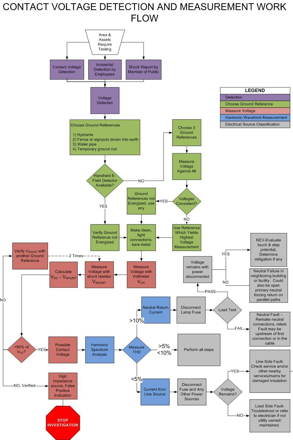
1 6 Contact Voltage 6.1 Background Contact voltage is not a step and touch potential problem. The risk of contact voltage is not from the momentary voltage, but the presence of an underlying fault, which is at or near line voltage. Published data from a New York utility shows the voltage measured and recorded by the utility during investigation of confirmed shock reports range from 1-120V and higher, with many voltages below 5V. These measurements were taken by workers arriving at the scene hours or perhaps days following the shock incident. This suggests that voltages from high impedance faults do not remain constant over time, but are functions of environmental conditions such as temperature and moisture levels in the soil. The reported shocks are typically associated with some type of fault to the distribution system, either an insulation breach on a supply conductor or faulty or open neutral. As defined in this Guide, these are instances of contact voltage, since they are not present when the system is operating normally, without a fault present. 6.2 Causes of Contact Voltage Contact voltage can occur at any place where the electric system breaks down from mechanical, thermal, chemical, or electrical stress. The root cause of this failure can be attributed to one or more of a list of causes, including: a) Infrastructure Decay As an installation ages, electrical insulation on cables and connectors tends to become brittle and may begin to crack, exposing energized components. Corrosion also reduces the strength of conduits, supports, cable jackets, and mechanical connections, all of which can initiate damage to insulation or neutral return paths. This effect is accelerated by the presence of moisture and other contaminants (road salt, for example) and by exposure to freeze/thaw cycles, especially around the edges of cable supports or duct edges. b) Inadequate Design Damaged wires can occur due to insufficient protection, mechanical support, insulation, or weatherproofing. There may also be inadequate grounding and bonding. Components installed in below grade enclosures that can fill with water or ice may also not be rated accordingly, leading to damaged wires and connections. c) Improper Installation Poor workmanship can directly result in a hazard to the public. Specific examples include substandard installation of hand taped insulation, reversed polarity, and insufficient mechanical protection of wires around stress points. Any component must be installed in accordance with the manufacturer s instructions. Such components are tested and qualified based on the assumption that they are installed properly; meaning that if they are not the product is not guaranteed to perform as designed. d) Accidental Damage Third parties may dig-in to a cable without knowing it, or compromise the integrity of a structure when working nearby. For example, concrete work on a sidewalk can leak into adjacent below grade hand wells, leading to damaged cables. Outdoor construction without a dig safe survey can lead to direct contact with electrical infrastructure by fence posts, road signs, guy wire supports, etc. Vibration and mechanical stress from traffic, ice heaving, and tree root penetration also cause inadvertent damage to underground infrastructure over time. e) Rodent Damage - 1 -
2 Rodents such as squirrels, mice and raccoons have been known to chew through wire or connector insulation. f) Vandalism/Copper Theft/Theft of Power Vandals can damage or remove access covers, resulting in exposed wires and the introduction of debris into electrical structures or streetlight bases. Thieves create hazards by removing neutral and ground conductors. Unauthorized connections to supply circuits may be made using unapproved components or work practices. g) Workmanship Insulation can be damaged during normal maintenance; pinched wires, loosened connections, reversed polarity have all been documented. Workers may pierce or remove insulation to test for voltage on an underground supply cable. If not properly re-insulated, this can leave a path for current leakage to cable supports, duct work, and other normally non-energized surfaces. h) Temporary Connections Temporary power connected for emergency restoration or seasonal lighting can, if not adequately safeguarded from the elements and from unauthorized access, create electrical hazards. See Appendix 6A for a description of waterproof seasonal lighting receptacles. Compromised conductor insulation results in a high-impedance fault which can go unnoticed by the party responsible for maintaining the asset until reported by a member of the public or identified through some kind of testing process. Experience has shown that any conductive structure in the vicinity of an electrical fault may become energized and pose a hazard to the public. 6.3 Detection and Testing of Contact Voltage Protection for low voltage supply circuits is typically rated at or above the maximum ampacity of conductors or the overload rating of the transformer. Detection of contact voltage is often the only proactive way to find and repair underground, low voltage electrical faults between utility transformers and customer points of connection. Tools are available to detect voltages as low as 1V AC or less, and can easily detect the voltage produced by leakage from a high impedance fault. These detections can be documented and repaired before a shock occurs to people or their animals. Detection of contact voltage is well documented using existing technology, has been shown to enhance public safety, and may enhance system reliability. Contact Voltage is detected in three ways. Direct detection A managed program of testing for contact voltage Incidental detection Discovery of energized structures during maintenance work or through abnormalities noticed during visual inspections or routine service work Reported shock Structure involved in a shock incident reported by the public Direct Detection An asset owner or electric utility may periodically test for contact voltage. The goal of such a program is to detect electrical faults underground or inside equipment housings by detecting voltage on the surface. Once detected, the utility can use a series of tests to determine whether a potential hazard exists and make decisions about repairs, if they are necessary. It is advisable to use the most sensitive means available to detect voltage from all possible faults and then use a more rigorous diagnostic process to rule out conditions which do not come from a fault and therefore are not likely to be hazardous. A sensitive detection process accomplishes the goal of proactively finding and repairing faults, preventing contact voltage incidents, and improving the safety and reliability of the system. Insensitive processes filter out possible hazards before any diagnostics can be performed. Incidental detection - 2 -


3 Detection of contact voltage can also occur during regularly scheduled repair and maintenance work. The addition of pre and post-work tests for contact voltage is recommended for both public and worker safety. These checks are ideally performed with a voltmeter against a grounded reference point. Reported shock First responders investigating a reported shock site should assume a fault condition exists and treat surfaces as energized until proven otherwise using actual voltage measurements against verified ground references. 6.4 Detection Equipment This guideline is not intended to suggest a requirement to use a specific technology. Every product should be tested in the intended operating area, as performance varies widely and may not meet marketing claims in actual field use. Users of any contact voltage method should consider the public safety ramifications resulting from the limitations of the method chosen. The most sensitive detection tools on the market, and the only Figure 15 HD Electric LV-S-5 Low Voltage Detector ones with any significant field use are the SVD2000 (Power Survey Company) and the LV-S-5 (HD Electric.) Digital voltmeters are used to verify indications from both of these, and can also be used to check for voltage before and after regular maintenance activities. Mobile Electric Field Detection The SVD2000 is a Mobile Electric Field Detector and Comparator [MEDAC.]. MEDAC detection relies on a capacitive sensor which detects small changes in the ambient electric field caused by the presence of an energized object. The sensor operates on a mobile platform, and deviations from background field levels are readily apparent to a trained technician as the sensor moves with relation to energized objects. The SVD2000 has been tested by an accredited independent laboratory for reliable detection of contact voltage in field operating environments. The system routinely detects surfaces energized to as little as 1 volt. It can test an area quickly, and provides both positive indication of an energized surface, and evidence that structures not giving rise to an electric field indication were not energized at the time of testing. It simultaneously detects voltage on all surfaces in an area: streetlights, manholes, fences, hand hole covers roadways, and sidewalks. As of this writing it is used in several cities in the US and Canada and has detected tens of thousands of instances of contact voltage. It is the most sensitive detection method currently available. MEDAC systems have limitations with respect to contact voltage detection. Underground distribution and mixed overhead/underground residential distribution are generally testable, though field levels from overhead high voltage lines can mask contact voltage signals in areas directly beneath primary distribution. Handheld Voltage Detectors Figure 14 SVD 2000 mobile detection system Courtesy Power Survey Company - 3 -


4 Handheld capacitive or pen testers have been used to detect contact voltage. They detect a potential difference exceeding a pre-set threshold between the sensor tip and the user s body, which is assumed to be capacitively coupled to ground. The HD Electric LV-S-5 is the most sensitive pen tester available as of this writing. Independent lab tests have documented detection of 5V in a lab environment, though its sensitivity to contact voltage in the field environment outside the laboratory has never been independently tested. As of this writing, all other marketed pen detectors are even less sensitive than the LV-S-5 and cannot be recommended for use in contact voltage detection. Along with direct voltmeter measurements, the LV-S-5 is one of two methods for detecting contact voltage directly under primary distribution lines. Figure 17 Digital Voltmeter with low impedance voltage measurement option built in (Fluke Model 117 shown as representative example) Pen testers have limitations as general contact voltage detection tools. The asset list-based process misses underground faults, which may energize sidewalks or other surfaces that do not appear on an asset list. Also, the 5 Volt threshold filters out findings without allowing the user to determine whether a potential hazard exists. The ground reference (the user) is always in proximity and sometimes in physical contact with the presumed energized surface, making the test subject to false negatives. The detector does not provide evidence that a tested surface was not energized at the time of test. Variations from user to user affect the reliability of detection and usage practices must be reinforced for all personnel: 1. Keep all body parts as far away from the object being tested as possible. Even accidental contact with a glove or boot will prevent a voltage indication from occurring, since the tester s body is the ground reference for the test. 2. Make solid metal-to-metal contact with each surface tested. Paint can mask energized surfaces from detection with a contact device. 3. Test all metal parts of an object separately. Metal surfaces in physical contact are not necessarily in electrical contact, especially if painted or corroded (see Fig 16.) 4. Grip the detector firmly with a full bare hand, no gloves. 5. Hold the detector at arms length and test from several angles to reduce the chance of standing on energized ground. 6. Test the battery frequently, especially in cold weather. Digital Voltmeter (DVM) with Low Impedance Feature A true RMS DVM is always used as a means of verifying the voltage once it has been detected by what ever means. Voltage measurements require several steps, including the use of a shunt resistor. Meter manufacturers offer built-in shunt resistors, called a low impedance function designed specifically for this purpose. Shunt resistors can also be purchased as an accessory or built from easily available parts. DVMs are impractical for large scale contact voltage surveys, but can be used for contact voltage detection where testing is done as part of routine maintenance or where assets are few in number Figure 16 Physical contact is not electrical contact. Pen tester must test each part of a lamp separately, e.g. pole, base, access door, bolt covers, mounting flange
5 6.5 Verification and Measurement Once a voltage is detected, it must be verified and measured. The measurement scenario is unconventional compared with typical utility work. Voltages may be variable and far below line voltage. Suitable ground reference points may not be close by. Significant contact and ground impedances are present. Active faults must also be assumed, placing nearby objects or the earth itself at an elevated voltage. Figure 18 illustrates the measurement circuit. In this measurement scenario, the investigator must accomplish the following tasks: 1. Identify suitable ground references 2. Prepare measurement surfaces 3. Eliminate false positive detections due to capacitive coupling 4. Accurately measure the voltage 5. Characterize the voltage source Identify suitable ground references A suitable ground reference must not be energized and must have low impedance to ground. Since the reference is only being used for measurement and is not intended to conduct fault current, it is not necessary to achieve the kind of grounding demanded for a code compliant grounding electrode; visible contact with the earth is usually sufficient. Ground references available at street level include but are not Figure 18 Measurement circuit of an energized streetlight, using hydrant as field ground. In this example, cause of contact voltage is open neutral in supply conductors. limited to fire hydrants, fence or sign posts driven into earth, grounded street furniture, and temporary grounds placed for the purpose of testing
6 General Do s and Don ts for selecting ground references: Do Carry long ground leads, 15m (50ft) minimum, to easily reach a suitable ground in the immediate area. Ground leads should have strong spring clamps. Do spend extra time making a clean, bare metal contact for your measurement. Do verify that ground references are not energized. Don t drive grounds without following any applicable dig safe procedures to avoid disturbing underground infrastructure. Don t use ground electrodes inside or directly adjacent to the object under test. If the object has voltage, the ground electrode will also be energized. Don t connect to an auxiliary part of a ground reference, such as an operating handle or knob. The main body is more likely to be solidly grounded. Verify ground references are not energized A handheld electric field meter like the ones pictured in Figure 19 can verify a reference ground has zero voltage. Any voltage on a surface gives rise to an electric field, so if electric field is zero, voltage is also zero. The device must be a meter, measuring electric field down to zero V/m, rather than simply indicating the presence of a field above some pre-set threshold. For this reason, pen testers are not suitable for validating ground references. In the absence of these meters, voltage measurements must be repeated using multiple references. The voltage reading should be the same among them if all references are at zero potential. If they differ, one or more references could be at elevated potential. The larger voltage measured is usually the correct one, though it is always appropriate to corroborate recorded values with more measurements rather than assuming a value on the basis of only one measurement. Re-verifying voltage measurements against field references using the shunt resistor provides a useful assurance that ground references have low impedance and do not contribute very large errors to measurement


7 Figure 19 Examples of handheld electric field detectors which can be used to check ground references for voltage (Power Survey Co EFD-100 and Walker Engineering Contact Voltage Detector pictured) Prepare measurement surfaces Measurement accuracy and repeatability depends on good references and clean connections. Reducing contact impedance to a practical minimum is necessary to make an accurate measurement in the field. Even bare metal surfaces like manhole covers have a resistive patina which must be removed from the test site to get repeatable measurements. Scratching with test lead tips will not penetrate this layer. Metal surfaces at both the measurement point and reference must be prepared with a wire brush or file to remove corrosion and paint. Proper equipment is also important for achieving and maintaining good surface contact in the field. A long ground lead, at least 50ft (15m) is necessary for reaching ground reference points, which are usually beyond the reach of standard voltmeter test leads. Strong spring clamps ensure solid contact throughout the process without having to move or adjust the connections. For non-metallic surfaces, good electrical contact depends on surface area. Utility regulations in dairy states and the guide published by NEETRAC suggest a copper plate with a weight applied to maximize electrode contact surface area. 1 This works well in a wet, electrolytic environment like a muddy feedlot, but not on a hard textured surface like a sidewalk. On sidewalks, a temporary metal rod driven between the cracks or a weighted, flexible metallic pad of foil or steel wool which can conform to the surface texture makes a more solid contact. Making electrical contact for a measurement on a dry day is difficult, but the same surface becomes fairly conductive after rain or snow. Extra attention to making good contact is especially important when following up on reports of electric shock which occurred in earlier, wetter conditions. 1 Patel, S; Lambert, F, Exposure Voltages - Concerns, Analysis, and Mitigation, Georgia Tech Research Corp. March 2008 pp
8 Eliminate false positive detections due to capacitive coupling Field voltage measurements are subject to false readings from capacitively coupled voltages and, especially at low voltages, large measurement error. Measurements with a shunt resistor eliminate false readings and minimize measurement error, resulting in accurate measurements that are repeatable from user to user. Workers, utility management, testing teams, and the general public all have an interest in accurate, repeatable measurements for efficient troubleshooting, business decisions, safety, and other reasons. A small extra effort reduces confusion at all levels of the process, ensures resources are not wasted pursuing false positive indications, and prevents crews from failing to recognize a real problem. Significant, measureable voltage can be present on ungrounded, isolated metal objects due to the influence of nearby high voltage sources such as power lines, lighting ballasts, or unshielded power cords. This phenomenon is called capacitive coupling, though the trade applies other terms to describe it, including phantom voltage. The object under test has a voltage, but no connection to a current source. Placing a small known load, or shunt, in parallel between the test leads of a digital voltmeter measures the voltage across the resistor from the voltage (source) to a ground. If no current flows, the voltage collapses to zero, eliminating false positive voltages due to capacitive coupling. Energized objects with some real current source will not collapse to zero, but will be reduced from the open circuit value (V OC ), without the shunt, according to Ohm s Law, (see Eq 1.) 2 V SHUNT V OC Z Z SOURCE SHUNT + Z SHUNT Equation 1 V SHUNT collapses to 0 in cases where voltage is sourced via capacitive coupling, as Z SOURCE >>Z SHUNT. This equation assumes zero contact impedance and ground impedance. Accurately measure voltage Errors due to contact and ground impedance cause disagreement between testing, repair, and management personnel and the small extra effort to record repeatable voltage measurements is worthwhile. After eliminating findings of capacitively coupled voltage, a few additional measurements will ensure accurate, repeatable data. By observing and minimizing the small change in voltage with the shunt engaged, the technician can minimize contact and ground impedances and get accurate readings that are repeatable from person to person. This positive feedback activity calls for a shunt resistor that can be quickly engaged and disengaged without disconnecting or moving the test leads, using a pushbutton or switch. It also calls for a shunt with resistance small enough to collapse the voltage from a capacitively coupled source, but large enough to control measurement error. 2 Kalokitis, D; Prazan, A, Technique for Accurate Voltage Measurement of Energized Street Level Objects IEEE PES 12 th Intl. Conf. on Trans. & Dist Const. and Live-Line Maint May, 2011, Providence, RI paper , ISBN
9 Measurement error is a function of the impedances in the measurement (Eq 2.) Ideally, the variability in measurements as a result of typical error values in the field should be <10%. Table 1 shows shunt voltage variability for a 20Ω source impedance, low total (ground and contact) impedances (50Ω) and more realistic value (250Ω), using 500Ω and 3000Ω shunt resistors. Those impedances will vary from technician to technician and it is easy to see how a lower shunt impedance results in large measurement variability which can cause confusion and miscommunication between multiple diagnostic or repair crews. V SHUNT ε = Z = V SHUNT Z Z + Z OC Z SOURCE SHUNT SOURCE SHUNT + Z + Z + Z SHUNT SOURCE CONTACT ε + Z GROUND MeasurementError (%) = (1 ε ) 100 Equation 2 Measurement error of shunt voltage is a function of the ground and contact impedances in the measurement circuit Z SHUNT 500Ω 3000Ω 500Ω 3000Ω Z S 20 Ω 20 Ω 20 Ω 20 Ω Z G +Z C 50 Ω 50Ω 250 Ω 250 Ω V SHUNT 0.88 V OC 0.98 V OC 0.65 V OC 0.92 V OC Error (%) 9% 2% 32% 8% Table 1 Measurement error for 500Ω and 3000Ω shunt resistances for a high impedance fault and low and typical values of ground and contact impedances. From the table, we see that error in measurements utilizing a 500Ω shunt is only low when ground and contact impedances are remarkably low. When more realistic values of ground and contact impedance are considered, measurement error increases rapidly. The importance of measurement accuracy and appropriately large shunt resistances was noted as early as Ω is the minimum recommended shunt resistance to minimize errors in measurement and reporting. Characterize the voltage source Voltage measurement alone cannot distinguish a fault condition from NEV, but harmonic analysis of the voltage can reveal its source, guide repair efforts, and help determine the possible hazard level. AC voltage sources can be one of three types: a) Phase (or supply) conductor fault- faults in internal wiring, service cable, or 3 rd party owned conductors 3 Gustafson, RJ, Instrumentation for Stray Voltage ASAE Proc. Of the Nat. Stray Voltage Symp. Oct 10-12, 1984, Syracuse, NY, pp
 Neutral to Earth voltage (NEV) - neutral voltage rise due to return current flowing through the impedance of the neutral Figure 20 Output screen showing 2.")
10 b) Neutral fault if neutral is faulty, return current is forced through the grounding electrode, energizing all bonded surfaces to a voltage proportional to Z G. c) Neutral to Earth voltage (NEV) - neutral voltage rise due to return current flowing through the impedance of the neutral Figure 20 Output screen showing 2.8% harmonic voltage distortion from a Fluke model 345, one of many tools available for harmonic spectrum analysis. distinguish a faulty neutral from an NEV. Phase and neutral conductor faults have the potential to deliver a shock under certain conditions. NEV is a stray voltage condition and generally not a shock hazard. Harmonic analysis allows confirmation that voltages are from the power system and whether the electric energy is from a phase source or neutral return current source. Further tests can Harmonic analysis works by measuring the degree of voltage distortion present in a measured voltage. Equipment is available from several manufacturers to do this analysis. Non-linear loads, including lighting ballasts, impose third harmonic [3HD] voltage distortion on neutral return current. Measurements of >10% 3HD indicate either a neutral fault or NEV. Phase, or line conductor sources are much closer to a pure 60Hz sine wave with <5% 3HD. When 3HD is between 5% and 10%, the source is less clear and should not be characterized from harmonic analysis alone. Further hands-on troubleshooting steps will be needed to locate the source. Figure 20 shows the output from a typical harmonic analyser. If harmonic analysis indicates a neutral return source, it is still not certain whether the voltage is the result of a fault or NEV. NEV is always present; a voltage difference will be present between the neutral conductor and anything it is bonded to and the local earth even if the neutral is completely disconnect from the load. NEV is also less than 8V in nearly all cases. If voltage is higher or if the voltage is only present with loads connected, a faulty neutral is the more likely cause. Another test is the load test. Disconnect the supply and neutral from the load and connect a load device, typically a W resistive load with a voltmeter to measure the voltage drop under load. If the voltage drops by more than 5% under load, a faulty neutral or neutral connector is the likely cause of the voltage. * Caution: Current flow on bonds or ground electrodes with loads disconnected or switched off is a sign of a hidden fault elsewhere. Treat all conductors as live unless proven dead
11 6.6 Sample Mitigation Steps These sample steps are designed for a 2-wire lighting circuit. Other scenarios may require more steps to perform harmonic analysis, determine the energy source, and assess whether voltage is due to a fault or normal condition. <5% Harmonic (Phase conductor source) 1. Test the hot and neutral wires for reversed polarity. 2. Open any disconnecting means, e.g. fuse, meter, main switch, etc. If the elevated voltage condition goes away, the fault is downstream of the fuse, switch, etc. Check connections and accessible parts of the streetlight for damage if the source is a phase fault. 3. Survey the area for additional sources of power, such as overhead cables from a streetlight or underground building service cables running adjacent or under the site. De-energize those one at a time to see if they are the cause. 4. If the elevated voltage condition remains on the streetlight with the fuse and any other sources disconnected, the fault is in the underground service conductor or its main feeder. Check for voltage on the service conduit, hand hole, sidewalk, or roadway. Disconnect the service at the feed structure. If voltage remains, disconnect other supply conductors which are routed near the energized surface. This may be a faulty service to a nearby kiosk, building, etc or a fault in the secondary feeder running past/under the site. Hot, dry patches of sidewalk or soil may be present, even in wet weather. This is a hazardous condition and should not be left unattended until voltage is mitigated. >10% harmonic (neutral conductor source) 1. Open any disconnecting means (see step 2 in phase conductor procedure.) 2. If voltage goes away with disconnecting means opened, check for neutral faults in the utility supply circuit by performing a load test with dummy load, typically 1000W or more. If voltage drop is >5%, check neutral connections or cable for possible repair or replacement. Start at the feed structure and work back towards the supply transformer. If the voltage drop under load is <5%, check for faulty neutral conductors or connections on the load side of the disconnect. 3. If voltage does not go away, source could be NEV or a neutral failure in another nearby building or street furniture. There may be electrical complaints or malfunctions that help identify a degraded neutral. Net current will also be present. That is, an ammeter placed around all supply and neutral conductors should measure zero amps, but Check neighbouring buildings or street furniture by deenergizing them one at a time. If the load test passes and voltage is low, <10V, the source is likely NEV. 4. To confirm NEV, measure for voltage on utility system neutral wire, compared with validated ground references. NEV will be measureable as a small, steady voltage with high harmonic distortion between the neutral and local ground references, even with no loads attached. NEV mitigation is covered in section 7 of the Guide. An engineering analysis will be required to determine the best course of action, which may be to do nothing. NOTE: Between 5-10% 3HD, source is likely a phase conductor, but could also be a neutral problem or NEV. Perform all steps
12 - 12 -
13 6.7 Developing a Contact Voltage Detection Program Contact voltage is present anywhere electric distribution is installed without a protection or monitoring system capable of detecting and eliminating it. This includes most underground low voltage distribution, and the problem only becomes more prominent as infrastructure ages. Due to the nature of a high impedance fault or a failing system neutral, a dangerous voltage can be present and can remain on a conductive surface which is otherwise properly grounded and bonded. In this circumstance, the protective device may not operate to remove the hazard if the fault current is below the trip threshold. This is analogous to the dangerous condition that exists when the earth is relied upon to act as a fault current return path. While the use of modern ground fault monitoring instrumentation and/or double (Class II) insulation might reduce the risk, it cannot be eliminated. The occurrence of system faults leading to contact voltage is common, therefore a program of regularly scheduled CVD is recommended. Recommendation: Asset owners create a written CVD policy to deal with the hazard in a proactive manner. Contact Voltage Detection Program Design Standard industry practices for controlling hazards in the workplace do not apply to public safety vis-à-vis contact voltage. Workplace hazards are controlled by: 1. Hazard elimination or substitution 2. Engineering controls 3. Administrative controls 4. Personal Protective Equipment A serious contact voltage detection and mitigation effort is the only source of data to target efforts or to measure their effectiveness. Hazard elimination can only occur after the specific electric fault has been detected. Engineering controls such as design changes or the application of guards or coatings reduce risk, but do not prevent the underlying hazard from occurring or existing. Existing codes do not specifically address the causes of contact voltage. Personal protective equipment can not be applied to the general public. Detection targets specific hazards for repair, yielding an immediate safety benefit and current, actionable data for designing safer electrical facilities in the future. In the absence of any prior or active Contact Voltage Detection [CVD] program, the asset owner s knowledge of contact voltage is anecdotal or sometimes non-existent. Contact voltages are only found and repaired when the underlying fault has caused some kind of collateral damage such as an outage, shock or electrical malfunction. Reports from the general public are an unreliable data source. The lack of general electrical knowledge leads to a tendency for electrical problems to be reported to police, fire, EMS, private electricians, or to go unreported. If contact voltage is reported, most utilities do not specifically track it. CVD creates traceable, actionable data to guide repairs and upgrades and improve system safety. Detecting voltages on normally non-energized objects in the underground system provides a set of locations where electrical faults may exist. The measurement and verification steps filter those findings down to exclude false detections and precisely quantify the voltage present. Harmonic analysis further separates the voltage findings into two categories: voltage from possible phase conductor faults, and voltage from either faulty neutrals or NEV. Further troubleshooting will again separate out the potentially hazardous system faults from the cases of stray voltage which occur on a normally operating system. System repairs finally eliminate the hazardous and potentially hazardous faults. Post-test analysis of this process gives the asset owner new information about what kinds of equipment, cable, connections, and locations are most often associated with contact voltage. The process yields both system improvement
14 and new knowledge about the state of the distribution system. Each subsequent cycle of the process improves the depth and accuracy of that knowledge and informs future decisions. Figure 21 CVD process for mitigating contact voltage and gaining knowledge about contact voltage on an underground distribution system Contact Voltage Detection Options Some utilities and asset owners in the USA are required to test their electrical assets twelve times per year, others test voluntarily, while others do no testing whatsoever and have no policy in place. Strategies to repair or prevent contact voltage are also diverse. Table 6-1 describes the mitigation strategies currently in use. Typically, a utility or asset owner will employ a combination of these strategies in concert to enhance safety and reliability based on the specific risk factors present in the distribution system. Recommendation: Asset owners review their assets and establish standards for CVD on new and existing installations based on the risk factors present Risk factors for Contact Voltage A few of the key Risk Factors for contact voltage on the distribution system are as follows:
15 a) Streetlights and other loads supplied from underground infrastructure are more likely to have buried or concealed faults than overhead systems, where conductors are mostly visible and out of reach of the public. b) High pedestrian/ pet traffic increases exposure to faults, if they are present. c) Conductive raceways/ equipment provide more paths for fault energy to objects or surfaces not intended to be energized, in the public right of way. d) Age, environmental conditions, high vehicular traffic, vandalism, and rodents may make some areas more prone to wear or damage. Note: Incidence of reported shock should not be the sole consideration when evaluating risk for the purpose of developing a CVD program. Many cases are reported to non-utility responders such as police/fire or not reported at all due to a lack of electrical safety awareness among the general public. Asset owners whose distribution systems or service areas encompass all or most of the risk factors may consider more aggressive or comprehensive testing options, whereas those systems or areas which are at lower risk, (ie. Overhead infrastructure, low or zero pedestrian exposure, newer infrastructure with nonmetallic ductwork and sensitive GFCI protection, etc.) may opt to perform less testing. Options for test intervals are as follows: test new installations upon commission one-time audit of existing infrastructure test only areas of high exposure or high risk spot checks at trouble-call times routine tests at re-lamp intervals Testing before and after maintenance work is performed regular testing independent of other maintenance cycles (typically done on a monthly, semi-annual or annual basis) performing multiple-asset, wide area mobile patrols (as opposed to manual, asset specific, foot patrols) any combination of the above An initial CVD effort provides a baseline of the number and type of contact voltage conditions that exist. A second test allows the asset owner to evaluate the success of repair efforts and estimate the rate of new infrastructure failure that occurs over time. Other mitigation strategies can be incorporated into maintenance and design procedure either systemwide, or on a targeted basis based on the data gathered from CVD. Table 6-1 describes some strategies that are used by utilities working to reduce contact voltage exposure to the public. Table 6-1 Summary of Contact Voltage Mitigation Strategies No. Lifecycle Phase Strategy Notes
16 1 Systems Design Prevention Specify equipment, protective devices, insulation, bonding conductors and system design with CV hazards in mind. 2 Equipment Manufacturing Prevention Manage purchasing process to ensure suppliers conform to applicable standards (UL, ISO, etc.) 3 Installation Prevention Avoid creating hazards during cable pulls and splicing processes through training, supervision and the use of proper tools and materials. 4 Commissioning Detection Test and inspect new assets. This is the best opportunity to detect and correct hazards from insulation that is defective or damaged during installation. 5 Operation & Maintenance Prevention Detection Corrective Action Operating equipment at or below its rating will prolong service life and reduce the probability of faults. Routine pre/post work testing by properly trained workers can detect contact voltage. 6 Ongoing Detection Corrective Action Analysis A CVD program covering areas of high risk or specific assets, such as underground infrastructure and streetlights, focuses resources on the specific areas where contact voltage is present and is most likely to occur in the future. Periodic, independent wide area auditing is strongly recommended where warranted by risk analysis. 7 Ongoing Education Conduct public awareness campaign. Coordinate with public/media relations personnel for bulletins, announcements, or electronic media to improve electrical safety knowledge. 8 Replacement Analysis Prevention Schedule replacement of aged infrastructure before problems occur. May include cables, poles, arms, streetlight luminaires or power distribution panels and wiring. Corrective Action CVD Program Management Asset owners may consider forming a team of qualified persons for the purpose of developing a CVD policy and a project charter. The team may consider coordinating with the owners of other electrical assets such as park lighting and traffic signals. Where it has been determined that a formal, comprehensive CVD program should be implemented by Asset owners, the following program elements may need to be incorporated: a management team or committee a policy or mission statement
17 a risk management assessment of assets written test procedures (for CVD) pre-determined acceptance standards (pass/fail criteria) test record and data collection forms a testing schedule (frequency, areas etc.) a test & repair protocol (who does what) an incidence reporting form and protocol tool and test instrument specifications test instrument calibration and inspection records procedures for barricading hazardous areas (if CV is found) personal protective equipment requirements a CV oriented review of engineering practices updates to existing asset inspection checklists changes to existing electrical work safety practices staffing requirements a budget Testing Personnel Persons trained in performing CVD may assist in troubleshooting but must report incidents immediately and defer repair work to qualified persons. This policy must apply whether the work is performed by the asset owners staff, by the street lighting maintenance contractor or by a specialist brought in for the specific purpose of CVD. Metal equipment housings or access covers should be checked both before regular maintenance work is performed, for worker safety, and after work is performed, for public safety. This protects against the possibility of worker induced faults. Repair Criteria for Contact Voltage Detections A detected voltage may or may not be a hazard and repair decisions are not obvious from a voltage measurement alone. There is no 'acceptable voltage threshold' for energized surfaces. The more detailed measurement and validation steps outlined in this guide allow discrimination between contact voltage from a faulted phase conductor and a neutral problem, and also between open neutrals and Stray Voltage due to NEV. Using these distinctions, a technician can more accurately describe a voltage as either contact voltage or stray voltage and then assess whether a hazard exists or could exist at the location under investigation. The best historical data collected to date would indicate very strongly that two common misconceptions ought to be dispelled. a) The voltage found on an energized surface cannot serve as an indicator of Mean-Time- Between-Failure, for the equipment. Any unintentionally energized surface of a street lighting pole or associated electrical enclosure indicates a possible fault condition. It should be investigated regardless of the voltage measurement. The root cause may be hazardous or benign, but voltage measurement alone is insufficient to make that determination
18 b) Unintended voltages measured on a surface are constant over time. The only reliable conclusion that can be made from the presence of contact voltage once NEV and capacitive coupling are eliminated as a cause, is that on some level, an electrical fault does exist. Many variables contribute to the voltage that may be discovered at any given time on the surface of faulted equipment. Since contact voltage is not constant, using just a voltage threshold as a guide for determining the degree of hazard is inadequate. The correct methodology is to find energized equipment conditions where they exist, then use the data gathered from measurement and diagnostics to make decisions about safety and repair activity. Safe voltage thresholds are used in NEV mitigation or worker protection standards which do not deal with faulted systems exposed to the general public. Those threshold values are unsuitable for the issue of CVD. Recommendation: When a legitimate electrical fault is found to exist, repairs ought to be effected in a timely manner before the situation deteriorates further, causes harm or results in the failure of equipment. Design Improvement Guideline A comprehensive review of the system design can identify risk areas which can be reduced or eliminated. Prevention at the design level is a way to reduce the possibility of future contact voltages over the long term. Such a review should include: grounding and bonding practices conductor clearances and burial depths guarding and mechanical protection conductor insulation grades connection and splicing methods, especially hand-taping and the use of non-submersible equipment in outdoor environments component specifications (non-conductive enclosures, light poles, luminaires, etc) protective devices (fuses, breakers, GFCI's etc) Recommendation: Owners review design and construction standards with contact voltage prevention in mind. Conclusion Contact voltage hazard mitigation is best accomplished by means of a balanced approach which includes system design, quality control, inspection, testing, risk analysis, life cycle analysis and infrastructure replacement. Three essential conclusions can be made: a) Distribution system and asset owners should proactively test for contact voltage. b) Any CVD program must be scaled and tailored to the needs of the community it serves. Various technologies and detection strategies may be employed and the asset manager must understand the limitations and risks of each approach
 type.")
19 c) Elevated voltage conditions found should be remedied in a timely fashion and proper records maintained. Appendix 6A Weatherproof while in use Receptacles For Seasonal Lighting Receptacles used on streetlight poles for seasonal lighting shall be of the ground fault circuit interrupter (GFCI) type. Receptacles with weatherproof while in use coverings are recommended for use in outdoor wet locations. These covers allow the receptacle to be protected from weather elements even when a power cord is plugged in. See Figure 22 Figure 22 In-Use Weatherproof Receptacle Cover The size of the receptacles used shall be 15 amps or as specified by the applicable electric code. The "while-in-use" weatherproof covers should be constructed from high-impact, UV-resistant non-metallic material or sturdy, corrosion-resistant metallic material
Technique for Accurate Voltage Measurement of Energized Street Level Objects
 Technique for Accurate Voltage Measurement of Energized Street Level Objects David Kalokitis (SM), Aaron Prazan (M) The demand and volume of stray voltage testing in urban areas have increased greatly
Contact Voltage Detection and Testing. David Kalokitis CTO Power Survey Company
 Contact Voltage Detection and Testing David Kalokitis CTO dkalokitis@powersurveyco.com Power Survey Company www.powersurveyco.com (888) PSC-2008 Who is Power Survey Company? Core business: Electrical hazard
EPG. by Chris C. Kleronomos
 April 1994 EFFECTIVE EQUIPMENT GROUNDING ECOS Electronics Corporation by Chris C. Kleronomos The quality of the electrical wiring and grounding in a facility containing sensitive electronic equipment is
Contact Voltage Detection
 Contact Voltage Detection Midwest Rural Energy Conference 48th Annual Rural Energy Conference March 11-12 La Crosse, Wisconsin Chad Hadley, Senior Engineer Overview Contact Voltage Definition History Equipment
Light Pole Safety Testing Mark Voigtsberger VP of Operations Power Quality Testing
 Light Pole Safety Testing Mark Voigtsberger VP of Operations Power Quality Testing Each year a handful of people are electrocuted, and hundreds more report being shocked, due to electrical wiring problems
CHAPTER 15 GROUNDING REQUIREMENTS FOR ELECTRICAL EQUIPMENT
 CHAPTER 15 GROUNDING REQUIREMENTS FOR ELECTRICAL EQUIPMENT A. General In a hazardous location grounding of an electrical power system and bonding of enclosures of circuits and electrical equipment in the
National Marine Manufacturers Association Compliance Specialist Examination A.C. Electrical (2018 Model Year) ABYC E-11 Supplement 56
 ABYC E-11 Supplement 56") 1. Two Electrical Technicians are discussing markings that are required for AC wiring. Tech A says that AC conductors must be rated for 600 volts and must have their jackets and individual conductors marked
1. Two Electrical Technicians are discussing markings that are required for AC wiring. Tech A says that AC conductors must be rated for 600 volts and must have their jackets and individual conductors marked
Article 225: Outside Branch Circuits And Feeders
 Part C: Code Book Questions Article 225: Outside Branch Circuits And Feeders 1.! Open (individual) aerial overhead conductors shall be insulated or covered when within! feet of a building.! (a) 10! (c)
PHASE ROTATION METER. Operating and Instruction Manual. a n d A C C E S S O R I E S
 PHASE ROTATION METER a n d A C C E S S O R I E S Operating and Instruction Manual HD ELECTRIC COMPANY 1 4 7 5 L A K E S I D E D R I V E WA U K E G A N, I L L I N O I S 6 0 0 8 5 U. S. A. PHONE 847.473.4980
The Basics of Insulation Testing
 The Basics of Insulation Testing Feature by Jim Gregorec IDEAL Industries, Inc. What Is Insulation Testing? In a perfect world, all the electrical current sent along a conductive wire would reach its intended
Industrial and Commercial Power Systems Topic 7 EARTHING
 The University of New South Wales School of Electrical Engineering and Telecommunications Industrial and Commercial Power Systems Topic 7 EARTHING 1 INTRODUCTION Advantages of earthing (grounding): Limitation
American Electrical Institute
 American Electrical Institute Oregon Electricians Continuing Education Grounding & Bonding (Article 250) 4 Hours American Electrical Institute PO Box 31131 Spokane, WA 99223 www.aeitraining.com Article
2011 / Circuit Tracer
 INSTRUCTION MANUAL 2011 / 00521 Circuit Tracer Read and understand all of the instructions and safety information in this manual before operating or servicing this tool. 52044992 2008 Greenlee Textron
Chapter 1. Applied Grounding and Bonding. Applied Grounding and Bonding 9/18/2011. Introduction. Introduction. Paul Dobrowsky Member NEC Panel 5
 Applied Grounding and Bonding Paul Dobrowsky Member NEC Panel 5 1 Introduction This presentation is a representative sample from the following Chapters of Applied Grounding and Bonding. Chapter 1, Introduction
Earthing of Electrical Devices and Safety
 Earthing of Electrical Devices and Safety JOŽE PIHLER Faculty of Electrical Engineering and Computer Sciences University of Maribor Smetanova 17, 2000 Maribor SLOVENIA joze.pihler@um.si Abstract: - This
... avoid using constructionstyle generators that have master GFCIs.
 Production Power on a budget: Ground-fault protection strategies, Part 3 BY GUY HOLT The third in a multipart exploration of how to safely use small portable generators in motion picture and live event
Electrical Measurement Safety. Sponsored By:
 Electrical Measurement Safety Sponsored By: About the Viewer Panel Slides: Go to the Links tab at the top and click on the link to download the PDF of the slides If you re watching the archive version,
SECTION 5 TRANSFORMERS
 SECTION 5 TRANSFORMERS Necessary transformers will be installed and maintained by The City of Aspen. The City of Aspen will not furnish transformers unless they are of standard size and voltage as established
User's Guide. AC Circuit Load Tester. Model CT70
 User's Guide AC Circuit Load Tester Model CT70 Introduction Congratulations on your purchase of the CT70 AC Circuit Load Tester. This device can detect circuit and wiring problems such as: Poor ground
Back to the Basics Current Transformer (CT) Testing
 Testing") Back to the Basics Current Transformer (CT) Testing As test equipment becomes more sophisticated with better features and accuracy, we risk turning our field personnel into test set operators instead of
Back to the Basics Current Transformer (CT) Testing As test equipment becomes more sophisticated with better features and accuracy, we risk turning our field personnel into test set operators instead of
SAFETY AND HEALTH STANDARD ELECTRICAL GROUNDING Effective Date: 07/17/10 Standard: Document Number: KUCSH0039 Rev: 4
 SAFETY AND HEALTH STANDARD ELECTRICAL GROUNDING Effective Date: 07/17/10 Standard: 16.10 Document Number: KUCSH0039 Rev: 4 16.10.1 INTRODUCTION 16.10.1.1 The intent of this standard is to ensure that continuity
Article 250 Grounding & Bonding
 Article 250 Grounding & Bonding AMERICAN ELECTRICAL INSTITUTE N16 W23217 Stone Ridge Dr. Waukesha, WI 53188 855-780-5046 www.aeitraining.com DISCLAIMER NOTE: This course is APPROVED for continuing education
2/15/2015. Current will always try to return to its source. In order for there to be current, there must be a complete circuit
 Current will always try to return to its source In order for there to be current, there must be a complete circuit Current will take as many paths or circuits available to it to return to the source The
A DUMMIES GUIDE TO GROUND FAULT PROTECTION
 A DUMMIES GUIDE TO GROUND FAULT PROTECTION A DUMMIES GUIDE TO GROUND FAULT PROTECTION What is Grounding? The term grounding is commonly used in the electrical industry to mean both equipment grounding
Pathfinder. Instruction Manual for: PF620 Circuit Tracer Kit
 Pathfinder Instruction Manual for: PF620 Circuit Tracer Kit Table of Contents Page Safety Considerations...3 Introduction...4 Specifications...5 Theory of Operation...6 Single Phase Circuits Locating Circuit
The Isolator/Surge Protector (ISP)
") The Isolator/Surge Protector (ISP) Technical Literature INTRODUCTION The Isolator/Surge Protector (ISP) is a solid-state device with logic-controlled circuitry which simultaneously provides isolation and
The Isolator/Surge Protector (ISP) Technical Literature INTRODUCTION The Isolator/Surge Protector (ISP) is a solid-state device with logic-controlled circuitry which simultaneously provides isolation and
The Isolator/Surge Protector (ISP)
") The Isolator/Surge Protector (ISP) Technical Literature INTRODUCTION The Isolator/Surge Protector (ISP) is a solid-state device with logic-controlled circuitry which simultaneously provides DC isolation
The Isolator/Surge Protector (ISP) Technical Literature INTRODUCTION The Isolator/Surge Protector (ISP) is a solid-state device with logic-controlled circuitry which simultaneously provides DC isolation
CONTINUING EDUC ATION
 3 CONTINUING EDUC ATION FOR WISCONSIN ELECTRICIANS 2017 NEC Article 250 2 Hours WISCONSIN CONTRACTORS INSTITUTE N16 W23217 Stone Ridge Drive Suite 290 Waukesha, WI 53188 262-409-4282 www.wcitraining.com
The Isolator/Surge Protector (ISP) Technical Literature
 Technical Literature") The Isolator/Surge Protector (ISP) Technical Literature INTRODUCTION The Isolator/Surge Protector (ISP) is a solid-state device with logic-controlled circuitry which simultaneously provides DC isolation
The Isolator/Surge Protector (ISP) Technical Literature INTRODUCTION The Isolator/Surge Protector (ISP) is a solid-state device with logic-controlled circuitry which simultaneously provides DC isolation
ENSURING PUBLIC SAFETY THROUGH PROPER EARTHING IN LOW VOLTAGE NETWORKS
 ENSURING PUBLIC SAFETY THROUGH PROPER EARTHING IN LOW VOLTAGE NETWORKS Sharmistha BHATTACHARYYA Enexis The Netherlands sharmirb@yahoo.com ABSTRACT Every electrical supply network should provide a proper
Customer Requirements RF Antenna Installations
 Application Terms Attachment requirements and clearances on the Pole for Radio Frequency (RF) antenna equipment installations. This standard is intended to allow electrical workers to perform their normal
Control Cable installation: Best Practice
 Control Cable installation: Best Practice Years of experience has taught Irri-Gator Product s technical personnel that it is virtually impossible to predict an installation s sensitivity to surges (whether
GROUNDED ELECTRICAL POWER DISTRIBUTION. Excerpt from Inverter Charger Series Manual BY: VIJAY SHARMA ENGINEER
 GROUNDED ELECTRICAL POWER DISTRIBUTION Excerpt from Inverter Charger Series Manual BY: VIJAY SHARMA ENGINEER .0 Conductors for Electrical Power Distribution For single-phase transmission of AC power or
99 Washington Street Melrose, MA Fax TestEquipmentDepot.com # # AAC Clamp Meter. Instruction Manual
 99 Washington Street Melrose, MA 02176 Fax 781-665-0780 TestEquipmentDepot.com #61-732 #61-736 400 AAC Clamp Meter Instruction Manual AC HOLD APO DC KMΩ mva WARNING Read First: Safety Information Understand
AT Advanced Wire Tracer. Users Manual
 AT-1000 Advanced Wire Tracer Users Manual AT-1000 Advanced Wire Tracer English Users Manual AT1000_Rev001 2008 Amprobe Test Tools. All rights reserved. Limited Warranty and Limitation of Liability Your
Grid Radar Installation Manual
 Grid Radar Installation Manual MODELS GN-RD-001 120V Single Phase / Wye, 240V Single Phase, with Neutral GN-RD-002 277V 3-Phase Wye, with Neutral GN-RD-003 480V 3-Phase Delta, no Neutral GN-RD-004 208V
AC INTERFERENCE OF TRANSMISSION LINES ON RAILWAYS: INFLUENCE OF TRACK-CONNECTED EQUIPMENT I. ABSTRACT
 AC INTERFERENCE OF TRANSMISSION LINES ON RAILWAYS: INFLUENCE OF TRACK-CONNECTED EQUIPMENT R. D. Southey, J. Liu, F. P. Dawalibi, Y. Li Safe Engineering Services & technologies ltd. 1544 Viel, Montreal,
SDCS-03 DISTRIBUTION NETWORK GROUNDING CONSTRUCTION STANDARD (PART-I) UNDERGROUND NETWORK GROUNDING. Rev. 01
 UNDERGROUND NETWORK GROUNDING. Rev. 01") SDCS-03 DISTRIBUTION NETWORK GROUNDING CONSTRUCTION STANDARD (PART-I) UNDERGROUND NETWORK GROUNDING Rev. 01 This specification is property of SEC and subject to change or modification without any notice
SDCS-03 DISTRIBUTION NETWORK GROUNDING CONSTRUCTION STANDARD (PART-I) UNDERGROUND NETWORK GROUNDING Rev. 01 This specification is property of SEC and subject to change or modification without any notice
Wisconsin Contractors Institute Continuing Education
 IMPORTANT NOTE: You should have received an email from us with a link and password to take your final exam online. Please check your email for this link. Be sure to check your spam folder as well. If you
SERVICING & METERING SERVICING AND METERING SECTION 5 SEC5:
 SECTION SERVICING AND METERING SECTION 1. SERVICING.... NST IMPEDANCE TESTING.... METERING... General Requirements.... CT METERING... 8 CT Metering General Requirements... 8 Existing Installation Alterations
Load-Trainer Transformer Simulator
 Load-Trainer Transformer Simulator XFMR-3BUSHING Three Bushing Transformer Simulator Operation Manual C-00879 XFMR-3BUSHING (11-11-15) Product Description 2 Components 3 Set-Up 4 Simulator Description
Licensed Electricians Practical Assessment (LEP)
") Licensed Electricians Practical Assessment (LEP) Surname: Given Names: Date: Time: Location: Assessment Time (includes reading and preparation time): At the end of this time you will be asked to stop.
Licensed Electricians Practical Assessment (LEP) Surname: Given Names: Date: Time: Location: Assessment Time (includes reading and preparation time): At the end of this time you will be asked to stop.
GENERAL OPERATIONAL PRECAUTIONS
 GENERAL OPERATIONAL PRECAUTIONS WARNING! When using electric tools, basic safety precautions should always be followed to reduce the risk of fire, electric shock and personal injury, including the following.
Electrical TP-18 February 2017 ELECTRICAL TECHNICAL PAPER 18 FREQUENTLY ASKED QUESTIONS ABOUT CATHODIC PROTECTION SYSTEM EQUIPMENT TESTING
 ELECTRICAL TECHNICAL PAPER 18 FREQUENTLY ASKED QUESTIONS ABOUT CATHODIC PROTECTION SYSTEM EQUIPMENT TESTING CATHODIC PROTECTION SYSTEM EQUIPMENT TESTING Question No. 1 What should I (the contractor) check
SDCS-03 DISTRIBUTION NETWORK GROUNDING CONSTRUCTION STANDARD (PART-II) OVERHEAD NETWORK GROUNDING. Rev. 01
 OVERHEAD NETWORK GROUNDING. Rev. 01") SEC DISTRIBUTION GROUNDING STANDARD SDCS-03 Part-II Rev.01 SDCS-03 DISTRIBUTION NETWORK GROUNDING CONSTRUCTION STANDARD (PART-II) OVERHEAD NETWORK GROUNDING Rev. 01 This specification is property of SEC
SEC DISTRIBUTION GROUNDING STANDARD SDCS-03 Part-II Rev.01 SDCS-03 DISTRIBUTION NETWORK GROUNDING CONSTRUCTION STANDARD (PART-II) OVERHEAD NETWORK GROUNDING Rev. 01 This specification is property of SEC
USER'S MANUAL DMR-6700
 USER'S MANUAL Multimeter True RMS DMR-6700 CIRCUIT-TEST ELECTRONICS www.circuittest.com Introduction This meter measures AC/DC Voltage, AC/DC Current, Resistance, Capacitance, Frequency (electrical & electronic),
2014 NEC Changes Part 1
 www.garyklinka.com Page 1 of 8 Instructions: Fee $20 1. Print these pages. 2. Circle the correct answers and transfer them to the answer sheet. 3. Page down to the last page for the verification forms
Load-Trainer Transformer Simulator
 Load-Trainer Transformer Simulator XFMR-4BUSHING Four Bushing Transformer Simulator Operation Manual Product Description 2 Components Set-Up 3 4 Simulator Description 4 Front Panel Description 5 Toggle
IMPORTANCE OF INSULATION RESISTANCE
 IMPORTANCE OF INSULATION RESISTANCE What is Good Insulation? Every electric wire in your plant whether it s in a motor, generator, cable, switch, transformer, etc., is carefully covered with some form
NEC 2014 Code Changes
 NEC 2014 Code Changes Articles 200-215.3 CHANGES FROM 2011 CODE ARE IN RED Chapter 2 - Wiring and Protection ARTICLE 200 Use and Identification of Grounded Conductors 200.2 General Grounded Conductors
Electrical testing safety Part 1: Preparing for absence of voltage testing
 APPLICATION NOTE Electrical testing safety Part 1: Preparing for absence of voltage testing James R. White, Training Director, Shermco Industries, Inc. OSHA and the NFPA 70E Standard for Electrical Safety
EASQ ELECTRICAL APPLIANCE SERVICEPERSON (QUALIFIED) MARKING SCHEDULE. SECTION 1 Marks Reference Marking notes Qu 1 A 10 MΩ (2 marks)
 MARKING SCHEDULE. SECTION 1 Marks Reference Marking notes Qu 1 A 10 MΩ (2 marks)") EASQ ELECTRICAL APPLIANCE SERVICEPERSON (QUALIFIED) MARKING SCHEDULE Notes: 1. (1mark) means that the preceding statement/answer earns 1 mark. 2. This schedule sets out the expected answers to the examination
EASQ ELECTRICAL APPLIANCE SERVICEPERSON (QUALIFIED) MARKING SCHEDULE Notes: 1. (1mark) means that the preceding statement/answer earns 1 mark. 2. This schedule sets out the expected answers to the examination
Instruction Manual for Digital Grounding Resistance Meter
 Instruction Manual for Digital Grounding Resistance Meter Instruction Manual for Digital Grounding Resistance Meter Table of Contents I. Overview...2 II. Open-case Inspection...3 III. Safety Precautions...4
Technical Seminar for Cathodic Protection to GOGC Design Unit Specialists. Dr. Nick Kioupis, Cathodic & Lightning Protection Section Head, DESFA
 Technical Seminar for Cathodic Protection to GOGC Design Unit Specialists Dr. Nick Kioupis, Cathodic & Lightning Protection Section Head, DESFA Photo of a typical T/R cabinet Impressed current stations
Grounding for Power Quality
 Presents Grounding for Power Quality Grounding for Power Quality NEC 250.53 states that ground resistance should be less than 25 ohms. Is this true? Grounding for Power Quality No! NEC 250.53 states
Electrical IP Red Seal Practice Exam
 Electrical IP Red Seal Practice Exam PRACTICE EXAM-3 1. What size 2 pole breaker must you use on a 3HP, 115V single phase motor? A. 40A B. 50A C. 80A. D. 100A. 2. An electrical equipment approved for use
SE-502 MANUAL GROUND-FAULT GROUND-CONTINUITY DETECTOR
 SE-502 MANUAL GROUND-FAULT GROUND-CONTINUITY DETECTOR March 5, 2002 PRELIMINARY 1 Publication: SE-502-M Document: S95-C502-00000 Printed in Canada. Copyright 2002 by Startco Engineering Ltd. All rights
Multi range AC current clamps (1000A / 100A / 5A / 0.5A) A 1281 Instruction manual Version 2.0, Code no
 A 1281 Instruction manual Version 2.0, Code no") (1000A / 100A / 5A / 0.5A) A 1281 Instruction manual Version 2.0, Code no. 20 751 696 Distributor: Manufacturer: METREL d.d. Ljubljanska cesta 77 1354 Horjul Slovenia web site: http://www.metrel.si e-mail:
(1000A / 100A / 5A / 0.5A) A 1281 Instruction manual Version 2.0, Code no. 20 751 696 Distributor: Manufacturer: METREL d.d. Ljubljanska cesta 77 1354 Horjul Slovenia web site: http://www.metrel.si e-mail:
Guide for Conducting a Stray Voltage Evaluation Under the MPSC Stray Voltage Rule 1
 Guide for Conducting a Stray Voltage Evaluation Under the MPSC Stray Voltage Rule 1 Introduction and Overall Purpose: This guide is intended to be used in conjunction with the administrative rules addressing
SINGLE PHASE BUCK & BOOST TRANSFORMERS INSTRUCTION MANUAL
 SINGLE PHASE INSTRUCTION MANUAL DIAGRAM D This manual applies to all single-phase buck & boost transformers sold by Larson Electronics. Please refer to the connection diagram on pages 4-6 for properly
2015 RIGOL TECHNOLOGIES, INC.
 Service Guide DG000 Series Dual-channel Function/Arbitrary Waveform Generator Oct. 205 TECHNOLOGIES, INC. Guaranty and Declaration Copyright 203 TECHNOLOGIES, INC. All Rights Reserved. Trademark Information
CHANCE Proximity Voltage Indicator
 Revision D 10/16 CHANCE Proximity Voltage Indicator Operating Instructions Model No. PSC4033737 For use with Capacitive Test Point through 500 kv AC NOTICE: Before operating a Chance Proximity Voltage
USER MANUAL. Delta Mains Energizer WARNING: READ ALL INSTRUCTIONS. speedrite ELECTRIC FENCING FOR THE SERIOUS FARMER
 USER MANUAL Delta Mains Energizer WARNING: READ ALL INSTRUCTIONS TM speedrite by ELECTRIC FENCING FOR THE SERIOUS FARMER Contents Electric fencing and your Speedrite energizer... 1 Installation... 2 Operation...
MASTECH MS5908. Circuit Analyzer
 MASTECH MS5908 Circuit Analyzer Operation Manual 2 General Instructions This circuit analyzer is a special test device designed for AC low-voltage distribution line quick fault location. With simple operation,
Stray Voltage and Swimming Pools
 Stray Voltage and Swimming Pools Marty L. Page, P.E. Southern Company malpage@southernco.com October 19 th 2009 2009 Jodie Lane National Conference for Stray Voltage Detection, Mitigation & Prevention
FTTH ENGINEERING AND INSTALLATION INTRODUCTION
 1 FTTH ENGINEERING AND INSTALLATION INTRODUCTION GROUNDING FTTH SYSTEMS AT THE HOME. By Dean Mischke, P.E., V.P. Grounding and bonding. Why are we worried about such an old school concept in the modern
Education & Training
 Distribution System Operator Certificate This program provides you with a proficient working knowledge in modern electric power distribution systems. These four classes are designed to walk students through
TAG5000 WIRELESS PHASER. Instruction Manual HD ELECTRIC COMPANY 1475 LAKESIDE DRIVE WAUKEGAN, ILLINOIS U.S.A.
 TAG5000 WIRELESS PHASER Instruction Manual TM HD ELECTRIC COMPANY 1475 LAKESIDE DRIVE WAUKEGAN, ILLINOIS 60085 U.S.A. PHONE 847.473.4980 FAX 847.473.4981 website: www.hdelectriccompany.com DESCRIPTION
EFCOG BEST PRACTICE # 211. Best Practice Title: Managing Hazards of Multiwire Branch Circuits Installed Before the 2008 NEC
 EFCOG BEST PRACTICE # 211 Best Practice Title: Managing Hazards of Multiwire Branch Circuits Installed Before the 2008 NEC Facility: DOE Complex Point of Contact: John (Jackie) McAlhaney, Savannah River
POWER DELEGATOR SERIES 7200A POWER DISTRIBUTION UNIT WITH POWER CONDITIONING GENERAL SPECIFICATIONS
 POWER DELEGATOR SERIES 7200A POWER DISTRIBUTION UNIT WITH POWER CONDITIONING GENERAL SPECIFICATIONS 1.0 SCOPE The following specification describes the features, design, and application of the Series 7200A
INSTALLATION AND MAINTENANCE MANUAL FOR GROUND MONITOR GM-250 COPYRIGHT 1983 AMERICAN MINE RESEARCH, INC.
 INSTALLATION AND MAINTENANCE MANUAL FOR GROUND MONITOR GM-250 COPYRIGHT 1983 AMERICAN MINE RESEARCH, INC. MANUAL PART NUMBER 180-0036 ORIGINAL: 1-17-83 REVISION: B (8-26-86) NOT TO BE CHANGED WITHOUT MSHA
UNITY/I TM. Installation Manual. UT3K, UT4K, UT5K and UT8K. Single-Phase Uninterruptible Power Systems
 UNITY/I TM UT3K, UT4K, UT5K and UT8K Single-Phase Uninterruptible Power Systems Installation Manual MLS-0351C-OL Copyright 1994-1997 Best Power. All rights reserved. å IMPORTANT SAFETY INSTRUCTIONS! SAVE
ET 40 - Electrician Theory Examination Marking Schedule
 ET 40 - Electrician Theory Examination Marking Schedule Notes:1. means that the preceding statement/answer earns 1 mark. 2. This schedule sets out the accepted answers to the examination questions. A marker
POWER TRACE TM TASCO, INC.
 POWER TRACE TM Instruction Manual PTL610 TASCO, INC. HOW YOUR POWER TRACE TM OPERATES The Power Trace TM is composed of two primary components: the Receiver and the Transmitter. When the Transmitter is
SECTION PANELBOARDS
 PART 1 - GENERAL 1.1 DESCRIPTION SECTION 26 24 16 PANELBOARDS SPEC WRITER NOTE: Delete between // --- // if not applicable to project. Also, delete any other item or paragraph not applicable in the section
CL900. True RMS 1000V 2000A 60MΩ ENGLISH. INSTRUCTION MANUAL 2000A Digital Clamp Meter. Measurement Technology
 ENGLISH INSTRUCTION MANUAL 2000A Digital Clamp Meter True RMS Measurement Technology NON-CONTACT VOLTAGE TESTING INRUSH CURRENT LOW IMPEDANCE DATA HOLD RANGE HOLD AUDIBLE CONTINUITY DIODE TEST CAPACITANCE
SI-125 Power Amplifier Manual 6205 Kestrel Road; Mississauga, Ontario; Canada; L5T 2A1 November 2016, Rev 0.5
 SI-125 Power Amplifier Manual 6205 Kestrel Road; Mississauga, Ontario; Canada; L5T 2A1 November 2016, Rev 0.5 Phone: (905) 564-0801 Fax: (905) 564-0806 www.telecor.com E:\T2-108\T2-M108-ABC\T2-M108-B.doc/AD
ELECTRIC GROUNDING AND WIRING REQUIREMENTS BOOTHS-METAL
 BELL SYSTEM PRACTICES Plant Series SECTION 508-100-100 Issue 3, October 1970 AT&TCo Standard ELECTRIC GROUNDING AND WIRING REQUIREMENTS BOOTHS-METAL I. GENERAL 1.01 This section is reissued to: Revise
VARIABLE TRANSFORMER TYPE CATHODIC PROTECTION RECTIFIER
 VARIABLE TRANSFORMER TYPE CATHODIC PROTECTION RECTIFIER INSTALLATION, OPERATION, & MAINTENANCE MANUAL 15360 116 Avenue, Edmonton, Alberta, Canada T5M 3Z6 Phone: (780) 447-1114 Fax: (780) 454-0004 Website:
SINGLE-PHASE VSV SWITCH
 May 2006 Supercedes: March 2006 SINGLE-PHASE VSV SWITCH INSTALLATION AND OPERATING MANUAL Table of Content: Page I. General...2 II. Specifications...2 III. Installation...2 IV. Maintenance...4 V. VSV Power
TN, TT & IT Earthing Arrangements
 TN, TT & IT Earthing Arrangements In IT and TN-C networks, residual current devices are far less likely to detect an insulation fault. In a TN-C system, they would also be very vulnerable to unwanted triggering
Digital Voltage Detector 0-999kV Operating Instructions VD1000PTM
 Digital Voltage Detector 0-999kV Operating Instructions VD1000PTM CONTENTS Limitation of Warranty and Liability 2 Product Safety Information 3 Design and Function Battery Replacement 4 Voltage Detection
SWITCHING SAFETY & RELIABILITY CONFERENCE
 SWITCHING SAFETY & RELIABILITY CONFERENCE JARGON WORKSHEET Energize (v) Energize is the process of applying rated voltage to circuit or equipment. Modified IEEE or OSHA from Adj. to verb. To make a piece
OPERATION & SERVICE MANUAL FOR FC 110 AC POWER SOURCE
 OPERATION & SERVICE MANUAL FOR FC 100 SERIES AC POWER SOURCE FC 110 AC POWER SOURCE VERSION 1.3, April 2001. copyright reserved. DWG No. FC00001 TABLE OF CONTENTS CHAPTER 1 INTRODUCTION... 1 1.1 GENERAL...
Stake-less earth / ground testing
 APPLICATION NOTE Stake-less earth / ground testing NEW DET14C and DET24C CLAMPS GETTING-AROUND ANY CHALLENGE What is stake-less testing? How does it work? Where and how can it be used? What are the potential
DP&L s Technical Requirements for Interconnection and Parallel Operation of Distributed Generation
 DP&L s Technical Requirements for Interconnection and Parallel Operation of Distributed Generation Technical Requirements for Interconnection and Parallel Operation of Distributed Generation Single Phase
Licensed Electricians Practical Assessment (LEP)
") Licensed Electricians Practical Assessment (LEP) Surname: Date: Given Names: Time: Assessment Time (includes 10 minutes reading time): At the end of this time you will be asked to stop. 4 hours Have you
Licensed Electricians Practical Assessment (LEP) Surname: Date: Given Names: Time: Assessment Time (includes 10 minutes reading time): At the end of this time you will be asked to stop. 4 hours Have you
Application Note. Detection of Partial Discharge Using Ultrasound. Detection of Partial Discharge Using Ultrasound. Problem. iriss.
 Detection of Partial Discharge Using Ultrasound Problem In electrical systems, especially above 1,000 Volts, sufficient and properly maintained equipment insulation helps ensure equipment longevity. However,
Transformers handling and transport
 Special tests (Credit: http://www.breakbulk.com/wp-content/uploads/2015/02/20141117160247x.jpg) Transformers handling and transport Damages that may arise and how to find them Table of contents summary
Section 3. Test Procedures
 Section 3. Information contained within this section shall be read in conjunction with all sections of this manual Non - Compliant Test Results Where acceptable results are not attained in accordance with
Webinar: An Effective Arc Flash Safety Program
 Webinar: An Effective Arc Flash Safety Program Daleep Mohla September 10 th, 2015: 2pm ET Agenda Arc Flash Defined and Quantified NFPA 70E / CSA Z 462 - Recent Updates What is the ANSI Z10 Hierarchy of
G.F.C.I. by Sam Goldwasser -- exerpts from: Sci.Electronics.Repair FAQ:
 1 of 6 8/4/2007 6:52 PM This page is from the original Code Check website. To see the latest version choose "Home Page New" Code Check 1998 by Redwood Kardon Home Page New Search What is a GFCI?: G.F.C.I.
ABCs of DMMs Multimeter features and functions explained Application Note
 ABCs of DMMs Multimeter features and functions explained Application Note Digital multimeters offer a wide selection of features. Choosing the right meter for the job can be challenging unless you know
High Voltage Pylon Earth Measurements
 High Voltage Pylon Earth Measurements Speaker: Gavin van Rooy Authors: Frank Barnes and Gavin van Rooy Tycom (Pty) Ltd PO Box 3546, Randburg, 2125, South Africa E-mail: frank@tycom.co.za Phone: 011 787
AN EXAMPLE OF A STANDARD ARC FLASH PPE LABELING STRATEGY
 The Electrical Power Engineers Qual-Tech Engineers, Inc. 201 Johnson Road Building #1 Suite 203 Houston, PA 15342-1300 Phone 724-873-9275 Fax 724-873-8910 www.qualtecheng.com AN EXAMPLE OF A STANDARD ARC
CONTENTS MS2033A. 1.Introduction Safety Information...01
 MS2033A AC Digital Clamp Meter User s Manual CAT III 600 V CONTENTS 1.Introduction...01 2.Safety Information...01 2.1 Precautions...02 2.2 Safety Symbols...03 3. Description...04 3.1 Front Panel...04 3.2
INSTRUCTION MANUAL UTL260
 INSTRUCTION MANUAL UTL260 1-800-547-5740 Fax: (503) 643-6322 www.ueitest.com email: info@ueitest.com Introduction The UTL260 has all the features and measurement functions that appliance technicians need.
Rev /13 SSRMAN-1B SERIES USERS MANUAL SSR INTELLIGENT BURST FIRING CONTROL COPYRIGHT 2013 NUWAVE TECHNOLOGIES, INC.
 Rev.2.2 12/13 MAN-1B SERIES USERS MANUAL INTELLIGENT BURST FIRING CONTROL COPYRIGHT 2013 MAN-1B Users Manual Page 2 TABLE OF CONTENTS 1. Ordering Codes... 2 2. Description... 2 2.1 Features... 3 3. Installation
Common Covered Task 408OP Inspect Cathodic Protection Rectifier
 Common Covered Task 408OP Inspect Cathodic Protection Rectifier Directions This training guide is to be used by a Veriforce Authorized Evaluator/Trainer and Trainee during on-thejob training (OJT) or prior
E N G I N E E R I N G M A N U A L
 1 1 1.0 PURPOSE The purpose of this document is to define policy and provide engineering guidelines for the AP operating companies (Monongahela Power Company, The Potomac Edison Company, and West Penn