I2C Demonstration Board LED Dimmers and Blinkers PCA9531 and PCA9551
|
|
|
- Leona O’Brien’
- 5 years ago
- Views:
Transcription

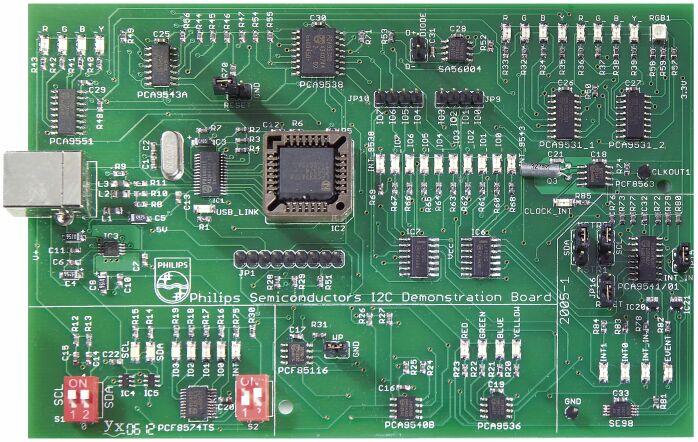
1 I2C Demonstration Board LED Dimmers and Blinkers PCA9531 and PCA9551 Oct, 2006
2 Intelligent I 2 C LED Controller RGBA Dimmer/Blinker /4/5 Dimmer PCA9531/2/3/4 1 MHz I²C Bus PCA963X PCA9533 PCA9533 PWM 1 PWM 2P Global P I²C Bus W : : W PWM : PWM 2 : PWM n M M HW Addr pin Osc Osc 160 Hz Osc 25 MhZ Osc 400 khz PCA953X PCA9533 PCA9533 PWM 1 OE HW Addr pin addr Sub1 addr Sub3 addr Sub2 addr. Group addr. 8-pin = no HW pin 10-pin = 2 HW pins 16-pin = 7 HW pins Blinker PCA9551/2/3/4 400 khz I²C Bus HW Addr pin PCA955X PCA9533 PCA9533 PWM 1 PWM 2 Osc 40 Hz Osc P W M : 2
3 PCA953x and PCA955x LED Dimmers & Blinkers In a nutshell 2, 4, 8 and 16 bits Open Drain output drivers that can drive up to 25 ma each Fully internal oscillator generates the programmed blinking or dimming schemes Each LED driver can be programmed to be: Fully OFF (default power up state) Fully ON Blinking / Dimming at Frequency_0, Duty_Cycle_0 Blinking / Dimming at Frequency_1, Duty_Cycle_1 8-bit resolution for the Blinking / Dimming frequencies and duty cycle Hex value Frequency Duty Cycle LED DIMMERS 0 (00h) 255 (FFh) 160 Hz 1 / 1.6 s 0 % 99.6 % 2.3 V to 5.5 V power supply with 5 V tolerant I/O s Device portfolio: # of bits LED BLINKERS PCA9550 PCA9553 PCA9551 PCA9552 LED BLINKERS 0 (00h) 255 (FFh) 40 Hz 1 / 6.4 s 100 % 0.4 % LED DIMMERS PCA9530 PCA9533 PCA9531 PCA9532 3
4 LED Lighting 3.3/5V 12V 12V Twisted-pair telephone wires, USB or flat ribbon cables Up to 15V logic levels, Include V CC & GND SCL 3.3/5 12V NO LIMIT to the number of connected bus devices! 3.3V SDA P82B96 P82B96 P82B96 P82B96 P82B96 5V SDA/SCL Slave Slave SDA/SCL SDA/SCL Slave SCL SDA/SCL SDA Slave PCA9665 Bus Controller ASIC 4
5 : 4-bit I 2 C LED Driver 4 LED drivers On, Off, Individual brightness, individual brightness + global blink/dim control Individual 8-bit (256 step) linear brightness control Global 8-bit linear brightness or blinking control 5 V tolerant programmable totem-pole / open drain structure: 10 ma source, 25 ma sink capability Output state change at ACK or STOP command Active low /OE input pin allowing hardware dimming / blinking Software programmable I 2 C addresses Sub calls allow groups of devices to be addressed at the same time Fast Mode Plus compatible I 2 C protocol 25 MHz fully internal oscillator Power Supply = 2.3 V to 5.5 V, - 40 to 85 C PCA bit and PCA bit also available I²C Bus Global PWM R PWM G PWM B PWM W PWM RGBW LED Mixing Part Number Package Dev per bus D16 SO DP1 TSSOP8 1 DP2 TSSOP10 4 PW TSSOP TK HVSON8 1 BS HVQFN
6 Bus Applications Each has an individual address set by the seven hardware pins and then up to four more sub call addresses that are programmed via the I²C-bus to allow individual control of each node and also groups of nodes to be controlled with one I²C command. Individual Sub 1 Sub 2 Sub 3 Sub V PCA9665 Bus Controller ASIC 6

7 Demonstration Board SW 5 & 6 used to turn bus pull up resistors on for only the master and termination cards. P82B96 buffers micro onto the high drive I²C-bus SW 4 send Output Enable signal to other boards RJ45 connections & cable used for I²C-bus, power and /OE signal between cards Push Buttons control micro and LEDs 60 V 350 ma FETs for higher brightness LED SW 7 sends 9V battery power over the cables Reprogram micro using ICP SW 8 turns on 9V battery power SW 1-3 sets address pins to GND or V CC allowing up to 8 board to be connected to the same micro 7


8 PCA9531 LED Blinker Hardware and Register definition 8

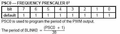
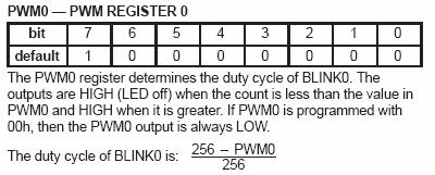
9 Device Hardware and Register definition INPUT Input Register: read back LED driver logic state Programmable I 2 C Addresses 8 devices in the same bus LSx LED Selector: selects the state of the LED Driver 5 V tolerant I 2 C bus 5 V tolerant, 25 ma capable open drain LED drivers Device powers up in a known state Active low RESET pin initializes the device in the same known state PSCx - Prescaler register: defines the frequency to be used for the LED PWMx Pulse Width Modulation register: defines the duty cycle for the LED x = 0 or 1 Internal oscillator does not require any additional components 9
10 Demonstration Board: PCA9551 Hardware Introduction MAIN I 2 C bus SDA SCL LEDs with different colors Only 4 outputs connected to LEDs From PCA9538 I/O0 PCA9551: I 2 C address: A[2:0] = 000 Address = 0xC0 Active Low RESET input controlled by the PCA9538 I/O0 needs to be configured as an output 10

11 Demonstration Board PCA9551 Hardware Introduction 11
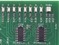
12 Switched 3.3 V. Demonstration Board PCA9531 Hardware Introduction Secondary I 2 C buses controlled by the PCA9543A Active Low RESET input controlled by the PCA9538 I/O1 and I/O4 need to be configured as outputs Unswitched 5 V MAIN I 2 C bus From PCA9538 I/O1. From PCA9538 I/O4 PCA9543A: I 2 C address: A[1:0] = 01 Address = 0xE2. LEDs with different colors RGB LED controlled by the two PCA9531 s PCA9531 device 1 and device 2: I 2 C address: A[2:0] = 100 Address = 0xC8 12
13 Demonstration Board PCA9531 Hardware Introduction 13
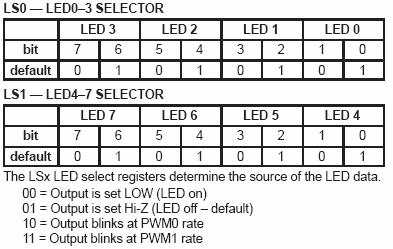
14 REGISTERS definition and PROGRAMMING PCA953x and PCA955x LED Dimmers and Blinkers have the same register mapping Registers: INPUT: allows reading of the LED driver outputs PSC0 & PWM0: define the Blinking or Dimming scheme 0 (8-bit value each) PSC1 & PWM1: define the Blinking or Dimming scheme 1 (8-bit value each) LS0 (up to LS3): defines the LED driver output state (4 possible states per output) A Blinking/Dimming scheme is defined by its period (PSC) and duty cycle (PWM) Programming differences Frequency and duty cycles calculation LED output state programming (2 bits per output) Value LED DIMMERS LED BLINKERS OFF ON ON OFF 10 Rate 0 Rate 0 11 Rate 1 Rate PWMx 256 ON OFF ON PSCx PWMx 256 ON = OFF = OFF ON OFF ON OFF ON PSCx LED BLINKERS LED DIMMERS Auto Increment feature Allows more than one register to be programmed (or read) with the same command Bit 4 in the Control Register (2 nd byte - contains the # of the register to be addressed) INPUT PSC0 PWM0 PSC1 PSC2 LS0 LS1 LS2 LS3 LED ON LED OFF 14
15 Hands-On 1: PCA9551GUI 1. Power sequence the board Board OFF then ON 2. Open the PCA9551 GUI: Device LED Blinkers and Dimmers PCA bit LED Blinker 3. Read all the registers. What do you read? All the LED outputs are OFF Both blinking rates default to slower blinking rate (once every ~ 6.4 s, 50 % duty cycle) 4. Program the 4 LEDs connected to the PCA9551 as following: LED0 ( Y): ON LED1 ( B): Blinking Rate 0 with Blinking Rate 0 = 1s 75 % duty cycle LED2 ( G): OFF LED3 ( R): Blinking Rate 1 with Blinking Rate 1 = 0.2 s (5 Hz) 25 % duty cycle Observe the result 5. Check the Auto Write option Program LED0 to LED3 to Blinking Rate 0 Use the maximum frequency for Blinking Rate 0 (40 Hz) and change the duty cycle from min to max back and forth. What do you observe? Using the maximum frequency of the LED blinkers allow brightness control by changing the duty cycle. However, the human eye can observe some flickering (no perfect dimming) due to the fact that the dimming frequency is not high enough. Effective dimming is achieved with a PWM frequency > 80 to 100 Hz 15

16 RGB COLOR MIXING Human eye sees the sum of primary colors average brightness: X % Red + Y % Green + Z % Blue 16
17 Using PWMs To Mix Colors In RGB LED To perform color mixing: Frequency high enough so that the human eye does not see the ON/OFF phases Brightness for each primary color (desired amount of each primary color) is controlled with the duty cycle Human eye sees the sum of primary colors average brightness:x % Red + Y % Green + Z % Blue 17

18 PCA9531 LED Dimmer GUI Device LED Blinkers and Dimmers PCA bit LED Dimmer Blinking / Dimming frequency and duty cycle selection Register Hexadecimal values LED output state selection I 2 C address: PCA9551 = 0xC0 PCA9531 = 0xC8 Auto Write Feature 18
19 Hands-On: RGB Color mixing using the 2 PCA9531 devices and the PCA9543A 1. Power sequence the board Board OFF then ON 2. a) Open the PCA9531 GUI: Device LED Blinkers and Dimmers PCA bit LED Dimmer b) Open the PCA9543A GUI: Device Multiplexers/Switches PCA9543A 2-channel switch with Interrupt Logic Reminder Architecture (see slide PCA9531 Hardware introduction): a) The 2 PCA9531 have the same I 2 C address and the PCA9543A allows to select one or the other (or both) b) The RGB LED is connected as following: - Red: LED4 of PCA9531 Device 1 (PCA9543A Channel 0) - Green: LED5 of PCA9531 Device 1 (PCA9543A Channel 0) - Blue: LED4 of PCA9531 Device 2 (PCA9543A Channel 1) 3. Use the PCA9543A and PCA9531 GUIs to control individually the 3 LEDs PCA 9543A 0 1 PCA9531 (1) PCA9531 (2) Rate 0 Rate 1 Rate 0 19
20 Hands-On: RGB Color mixing using the 2 PCA9531 devices and the PCA9543A When it is understood how the RGB LEDs are controlled, program the two PCA9531 devices to display a not too bright purple color using the right amount of Red, Green and Blue (Hint: Use the PCA9543A (Switch) and PCA9531 GUIs to control individually the 3 LEDs) Blink the LEDs displaying purple color Now, program the two PCA9531 devices to display a not too bright yellow color. Blink the LEDs displaying Yellow color 20
21 Hands-On 3: Using the Expert Mode Write the following I 2 C sequences (Red) using the Expert Mode and execute it step by step 1. Connect Jumpers SDA and SCL to Master 0 (Higher position) and enable Jumper JP15 (INT_IN) LED INT_IN should be ON 2. Power sequence the board Board OFF then ON 3. Write to the PCA9551 to have LED0/LED3 blinking at 1 Hz, 50% duty cycle and LED1/LED2 blinking at 2 Hz, 50 % duty cycle 4. Write to the 2 PCA9531 to have the 8 discrete blinking at 1 Hz, 50 % duty cycle and the RGB LED displaying a white color 5. Run the sequence above during 2s 6. Reset the 2 PCA9531 and the PCA9551 during 2s 7. Clear the reset conditions and loop back to the 1 st instruction Hints, methodology and Technical Information: Use the GUI s to define the register values (easier than calculating with the formulas) Resets are active low PCA9551 Reset line controlled by I/O0 ; PCA9531 Reset line controlled by I/O4 21
22

23 1= AUTO INCREMENT 23
24 24
25 25
PCA bit I 2 C LED driver with programmable blink rates INTEGRATED CIRCUITS May 05. Product data Supersedes data of 2003 Feb 20
 INTEGRATED CIRCUITS 8-bit I 2 C LED driver with programmable blink rates Supersedes data of 2003 Feb 20 2003 May 05 Philips Semiconductors 8-bit I 2 C LED driver with programmable blink rates FEATURES
LED controllers. Voltage-switch drivers, constant-current drivers, and Flash LED drivers
 LED controllers - drivers, constant-current drivers, and Flash LED drivers LEDs are used in a wide range of applications, from low-end status indicators to high-end video displays. System designers often
INTEGRATED CIRCUITS. PCA bit I 2 C LED dimmer. Product data Supersedes data of 2003 Feb May 02. Philips Semiconductors
 INTEGRATED CIRCUITS Supersedes data of 2003 Feb 26 2003 May 02 Philips Semiconductors DESCRIPTION The is a 16-bit I 2 C-bus and SMBus I/O expander optimized for dimming LEDs in 256 discrete steps for Red/Green/Blue
INTEGRATED CIRCUITS. PCA bit I 2 C LED dimmer. Product data Supersedes data of 2003 May Oct 01. Philips Semiconductors
 INTEGRATED CIRCUITS Product data Supersedes data of 2003 May 02 2004 Oct 01 Philips Semiconductors DESCRIPTION The is a 16-bit I 2 C-bus and SMBus I/O expander optimized for dimming s in 256 discrete steps
PCA General description. 8-bit Fm+ I 2 C-bus LED driver
 Rev. 7.1 18 December 2017 Product data sheet 1. General description The is an I 2 C-bus controlled 8-bit LED driver optimized for Red/Green/Blue/mber (RGB) color mixing applications. Each LED output has
PCA General description. 4-bit Fm+ I 2 C-bus LED driver
 PC9633 Rev. 04 4 March 2008 Product data sheet 1. General description The PC9633 is an I 2 C-bus controlled 4-bit LED driver optimized for Red/Green/Blue/mber (RGB) color mixing applications. Each LED
INTEGRATED CIRCUITS. PCA bit I 2 C LED dimmer. Product data sheet Supersedes data of 2004 Sep Oct 01. Philips Semiconductors
 INTEGRATED CIRCUITS Supersedes data of 2004 Sep 14 2004 Oct 01 Philips Semiconductors The initial setup sequence programs the two blink rates/duty cycles for each individual PWM. From then on, only one
CAT bit Programmable LED Dimmer with I 2 C Interface FEATURES DESCRIPTION APPLICATIONS TYPICAL APPLICATION CIRCUIT
 16-bit Programmable Dimmer with I 2 C Interface FEATURES 16 drivers with dimming control 256 brightness steps 16 open drain outputs drive 25 ma each 2 selectable programmable blink rates: frequency: 0.593Hz
CAT bit Programmable LED Dimmer with I 2 C Interface DESCRIPTION FEATURES APPLICATIONS TYPICAL APPLICATION CIRCUIT
 16-bit Programmable Dimmer with I 2 C Interface FEATURES 16 drivers with dimming control 256 brightness steps 16 open drain outputs drive 25 ma each 2 selectable programmable blink rates: frequency: 0.593Hz
I2C Encoder. HW v1.2
 I2C Encoder HW v1.2 Revision History Revision Date Author(s) Description 1.0 22.11.17 Simone Initial version 1 Contents 1 Device Overview 3 1.1 Electrical characteristics..........................................
EVDP610 IXDP610 Digital PWM Controller IC Evaluation Board
 IXDP610 Digital PWM Controller IC Evaluation Board General Description The IXDP610 Digital Pulse Width Modulator (DPWM) is a programmable CMOS LSI device, which accepts digital pulse width data from a
PCU General description. 24-bit UFm 5 MHz I 2 C-bus 100 ma 40 V LED driver
 Rev. 8 December 20 Product data sheet. General description The is a UFm I 2 C-bus controlled 24-bit LED driver optimized for voltage switch dimming and blinking 00 ma Red/Green/Blue/Amber (RGBA) LEDs.
PCA9633DEMO User Manual. Overview
 PCA9DEMO Overview The PCA9 Demo Board demonstrates the Philips PCA9 Fast Mode Plus -bit I²C LED Dimmer IC. Four LEDs are connected to the PCA9 and through individual pulse width modulation (PWM) of each
PCA General description. 4-bit Fm+ I 2 C-bus low power LED driver
 PC9632 Rev. 03 15 July 2008 Product data sheet 1. General description The PC9632 is an I 2 C-bus controlled 4-bit LED driver optimized for Red/Green/Blue/mber (RGB) color mixing applications. The PC9632
PCA General description. 16-bit Fm+ I 2 C-bus LED driver
 Rev. 05 22 March 2007 Product data sheet 1. General description The is an I 2 C-bus controlled 16-bit LED driver optimized for Red/Green/Blue/mber (RGB) color mixing applications. Each LED output has its
PCA9955A. 1. General description. 16-channel Fm+ I 2 C-bus 57 ma/20 V constant current LED driver
 16-channel Fm+ I 2 C-bus 57 ma/20 V constant current LED driver Rev. 3 14 October 2014 Product data sheet 1. General description The is an I 2 C-bus controlled 16-channel constant current LED driver optimized
3-Channel Fun LED Driver
 3-Channel Fun LED Driver Description is a 3-channel fun LED driver which features two-dimensional auto breathing mode. It has One Shot Programming mode and PWM Control mode for RGB lighting effects. The
I2C Demonstration Board I 2 C-bus Protocol
 I2C 2005-1 Demonstration Board I 2 C-bus Protocol Oct, 2006 I 2 C Introduction I ² C-bus = Inter-Integrated Circuit bus Bus developed by Philips in the early 80s Simple bi-directional 2-wire bus: serial
LP3943/LP3944 as a GPIO Expander
 LP3943/LP3944 as a GPIO Expander General Description LP3943/44 are integrated LED drivers with SMBUS/I 2 C compatible interface. They have open drain outputs with 25 ma maximum output current. LP3943 has
DS1307ZN. 64 X 8 Serial Real Time Clock
 64 X 8 Serial Real Time Clock www.dalsemi.com FEATURES Real time clock counts seconds, minutes, hours, date of the month, month, day of the week, and year with leap year compensation valid up to 2100 56
DS4000 Digitally Controlled TCXO
 DS4000 Digitally Controlled TCXO www.maxim-ic.com GENERAL DESCRIPTION The DS4000 digitally controlled temperature-compensated crystal oscillator (DC-TCXO) features a digital temperature sensor, one fixed-frequency
L, LTC, LTM, LT are registered trademarks of Linear Technology Corporation. PowerPath
 DESCRIPTION WARNING! Do not look directly at operating LED. This circuit produces light that can damage eyes. Demo Circuit 1402 is a Highly Integrated 6-Channel Portable PMIC with a push button controller,
PCA9956B. 1. General description. 24-channel Fm+ I 2 C-bus 57 ma/20 V constant current LED driver
 24-channel Fm+ I 2 C-bus 57 m/20 V constant current LED driver Rev. 1.1 15 December 2015 Product data sheet 1. General description The is an I 2 C-bus controlled 24-channel constant current LED driver
PCU General description. 16-channel UFm I 2 C-bus 57 ma constant current LED driver
 Rev. 2. 29 June 205 Product data sheet. General description The is an Ultra-Fast mode (UFm) I 2 C-bus controlled 6-channel constant current LED driver optimized for dimming and blinking 57 ma Red/Green/Blue/Amber
L, LTC, LTM, LT are registered trademarks of Linear Technology Corporation. PowerPath
 DESCRIPTION WARNING! Do not look directly at operating LED. This circuit produces light that can damage eyes. Demo Circuit 1592A is a Highly Integrated Portable Product PMIC with a pushbutton controller,
IS31FL CHANNEL FUN LED DRIVER July 2015
 1-CHANNEL FUN LED DRIVER July 2015 GENERAL DESCRIPTION IS31FL3191 is a 1-channel fun LED driver which has One Shot Programming mode and PWM Control mode for LED lighting effects. The maximum output current
RB-Dev-03 Devantech CMPS03 Magnetic Compass Module
 RB-Dev-03 Devantech CMPS03 Magnetic Compass Module This compass module has been specifically designed for use in robots as an aid to navigation. The aim was to produce a unique number to represent the
CoolEx User Manual 2008 XDIMAX LTD. Revision 1.0
 CoolEx User Manual Revision 1.0 2 CoolEx User Manual Table of Contents Foreword 0 Part I Overview 3 Part II Configuration and Setup 4 1 Terminals Layout... 4 2 Modbus Address... Switch 4 Part III Functional
PCA General description. 2. Features and benefits. 16-bit I 2 C-bus LED dimmer
 Rev. 4.1 22 August 2016 Product data sheet 1. General description The is a 16-bit I 2 C-bus and SMBus I/O expander optimized for dimming LEDs in 256 discrete steps for Red/Green/Blue (RGB) color mixing
PCA General description. 16-channel, 12-bit PWM Fm+ I 2 C-bus LED controller
 Rev. 02 16 July 2009 Product data sheet 1. General description The is an I 2 C-bus controlled 16-channel LED controller optimized for LCD Red/Green/Blue/mber (RGB) color backlighting applications. Each
PCA General description. 2. Features. 4-bit I 2 C-bus LED dimmer
 Rev. 03 27 April 2009 Product data sheet 1. General description 2. Features The is a 4-bit I 2 C-bus and SMBus I/O expander optimized for dimming LEDs in 256 discrete steps for Red/Green/Blue (RGB) color
INTEGRATED CIRCUITS. PCA9544A 4-channel I 2 C multiplexer with interrupt logic. Product data sheet Supersedes data of 2004 Jul 28.
 INTEGRATED CIRCUITS Supersedes data of 2004 Jul 28 2004 Sep 29 DESCRIPTION The is a 1-of-4 bi-directional translating multiplexer, controlled via the I 2 C-bus. The SCL/SDA upstream pair fans out to four
IS31FL3190 IS31FL CHANNEL FUN LED DRIVER. Preliminary Information November 2015
 1-CHANNEL FUN LED DRIVER GENERAL DESCRIPTION IS31FL3190 is a 1-channel fun LED driver which has One Shot Programming mode and PWM Control mode for LED lighting effects. The maximum output current can be
IS31FL3208A 18-CHANNEL LED DRIVER; SELECTABLE PWM FREQUENCY. August 2018
 18-CHANNEL LED DRIVER; SELECTABLE PWM FREQUENCY August 2018 GENERAL DESCRIPTION is comprised of 18 constant current channels each with independent PWM control, designed for driving LEDs, PWM frequency
7 OUT1 8 OUT2 9 OUT3 10 OUT4 11 OUT5 12 OUT6 13 OUT7 14 OUT8 15 OUT9 16 OUT10 17 OUT11 18 OUT12 19 OUT13 20 OUT14 21 OUT15 22 OUT16 OUT17 23 OUT18
 18 CHANNELS LED DRIVER June 2017 GENERAL DESCRIPTION IS31FL3218 is comprised of 18 constant current channels each with independent PWM control, designed for driving LEDs. The output current of each channel
Programming the Dallas/Maxim DS MHz I2C Oscillator. Jeremy Clark
 Programming the Dallas/Maxim DS1077 133MHz I2C Oscillator Jeremy Clark Copyright Information ISBN 978-0-9880490-1-7 Clark Telecommunications/Jeremy Clark June 2013 All rights reserved. No part of this
16 Channels LED Driver
 16 Channels LED Driver Description The SN3216 is a fun light LED controller with an audio modulation mode. It can store data of 8 frames with internal RAM to play small animations automatically. SN3216
DS1803 Addressable Dual Digital Potentiometer
 www.dalsemi.com FEATURES 3V or 5V Power Supplies Ultra-low power consumption Two digitally controlled, 256-position potentiometers 14-Pin TSSOP (173 mil) and 16-Pin SOIC (150 mil) packaging available for
PCA General description. 16-bit Fm+ I 2 C-bus 100 ma 40 V LED driver
 Rev. 03 31 ugust 2009 Product data sheet 1. General description The is an I 2 C-bus controlled 16-bit LED driver optimized for voltage switch dimming and blinking 100 m Red/Green/Blue/mber (RGB) LEDs.
INTEGRATED CIRCUITS. Control signals. 8 bits
 INTEGRATED CIRCUITS µ Controller, µ Processor, DSP or ASIC Control signals 8 bits PCA9564 SDA SCL Abstract Philips Semiconductors family of bus controllers are detailed in this application note. PCA9564
DALI slave, one to four channels PWM and I2C output
 DALI slave, one to four channels PWM and I2C output 1. Features DALI to PWM and I2C controller Pin selectable 1 to 4 channels Access to raw arc power values via I2C Access to mapped brightness values via
IS31FL3209 IS31FL CHANNELS LED DRIVER; 1/24 DC SCALING WHITE BALANCE. December 2017
 18 CHANNELS LED DRIVER; 1/24 DC SCALING WHITE BALANCE December 2017 GENERAL DESCRIPTION IS31FL3209 is comprised of 18 constant current channels each with independent PWM control, designed for driving LEDs,
Debugging a Boundary-Scan I 2 C Script Test with the BusPro - I and I2C Exerciser Software: A Case Study
 Debugging a Boundary-Scan I 2 C Script Test with the BusPro - I and I2C Exerciser Software: A Case Study Overview When developing and debugging I 2 C based hardware and software, it is extremely helpful
IS31FL3731 AUDIO MODULATED MATRIX LED DRIVER. May 2013
 AUDIO MODULATED MATRIX LED DRIVER May 2013 GENERAL DESCRIPTION The IS31FL3731 is a compact LED driver for 144 single LEDs. The device can be programmed via an I2C compatible interface. The IS31FL3731 offers
VIO 0.47 F CS2 CS1 SW6 SW5 SW2 SW1 PGND. Figure 1 Typical Application Circuit (6 8)
") 6 8 DOTS MATRIX LED DRIVER WITH INDIVIDUAL AUTO BREATH FUNCTION GENERAL DESCRIPTION The IS31FL3738 is a general purpose 6 8 LEDs matrix driver with 1/12 cycle rate. The device can be programmed via an
6 8 DOTS MATRIX LED DRIVER WITH INDIVIDUAL AUTO BREATH FUNCTION GENERAL DESCRIPTION The IS31FL3738 is a general purpose 6 8 LEDs matrix driver with 1/12 cycle rate. The device can be programmed via an
16-channel, 12-bit PWM Fm+ I 2 C-bus LED controller
 Rev. 3 2 September 2010 Product data sheet 1. General description The is an I 2 C-bus controlled 16-channel LED controller optimized for LCD Red/Green/Blue/mber (RGB) color backlighting applications. Each
DS1065 EconOscillator/Divider
 wwwdalsemicom FEATURES 30 khz to 100 MHz output frequencies User-programmable on-chip dividers (from 1-513) User-programmable on-chip prescaler (1, 2, 4) No external components 05% initial tolerance 3%
IS31FL3746A 24-RGB MATRIX LED DRIVER. Preliminary Information September 2018
 24-RGB MATRIX LED DRIVER Preliminary Information September 2018 GENERAL DESCRIPTION The IS31FL3746A is a general purpose 18 n (n=1~4) LED Matrix programmed via 1MHz I2C compatible interface. Each LED can
10 Zone RGB-W LED Controller
 10 Zone RGB-W LED Controller This LED RGB controller is specifically designed to be used with multiple receptors and also has the possibility to control individually each receptor. Main Functionalities:
Pin Assignment SEG28 SEG29 SEG30 SEG31 SEG32 SEG33 SEG34 SEG35 SEG36 SEG37 SEG38 VDD SDA SCL COM0 COM1 COM2 COM3 COM4 COM5 COM6 COM
 General Description Features VK2C23 56 4 / 52 8 LCD Driver Controller The VK2C23 device is a memory mapping and multi-function LCD controller driver. The Display segments of the device are 224 patterns
Servo click. PID: MIKROE 3133 Weight: 32 g
 Servo click PID: MIKROE 3133 Weight: 32 g Servo click is a 16-channel PWM servo driver with the voltage sensing circuitry. It can be used to simultaneously control 16 servo motors, each with its own programmable
7 OUT1 8 OUT2 9 OUT3 10 OUT4 11 OUT5 12 OUT6 13 OUT7 14 OUT8 15 OUT9 16 OUT10 17 OUT11 18 OUT12 19 OUT13 20 OUT14 21 OUT15 22 OUT16 OUT17 23 OUT18
 18 CHANNELS LED DRIVER GENERAL DESCRIPTION is comprised of 18 constant current channels each with independent PWM control, designed for driving LEDs. The output current of each channel can be set at up
2F. No.25, Industry E. 9 th Rd., Science-Based Industrial Park, Hsinchu, Taiwan Application Note of OGM220, AN001 V1.8
 Application Note of OGM220, AN001 V1.8 1.0 Introduction OGM220 series is a dual channels NDIR module having a digital output directly proportional to CO2 concentration. OGM220 is designed for multi-dropped
IS31FL3206 IS31FL CHANNEL LED DRIVER; SELECTABLE PWM FREQUENCY. Preliminary Information May 2018
 12-CHANNEL LED DRIVER; SELECTABLE PWM FREQUENCY Preliminary Information May 2018 GENERAL DESCRIPTION IS31FL3206 is comprised of 12 constant current channels each with independent PWM control, designed
Trademarks & Copyright
 Smart Peripheral Controller Neo DC Motor 1.2A Trademarks & Copyright AT, IBM, and PC are trademarks of International Business Machines Corp. Pentium is a registered trademark of Intel Corporation. Windows
Experiment#6: Speaker Control
 Experiment#6: Speaker Control I. Objectives 1. Describe the operation of the driving circuit for SP1 speaker. II. Circuit Description The circuit of speaker and driver is shown in figure# 1 below. The
PVCC SW6 SW5 SW2 SW1 IS31FL3742 CS30 CS29 CS2 20 CS1. Figure 1 Typical Application Circuit (Single Color: 30x6)
") 30 6 DOTS MATRIX LED DRIVER December 2017 GENERAL DESCRIPTION The IS31FL3742 is a general purpose 30 6 LED Matrix programmed via an I2C compatible interface. Each LED can be dimmed individually with 8-bit
30 6 DOTS MATRIX LED DRIVER December 2017 GENERAL DESCRIPTION The IS31FL3742 is a general purpose 30 6 LED Matrix programmed via an I2C compatible interface. Each LED can be dimmed individually with 8-bit
Advanced Analog Technology, Inc. October 2009 AAT1301 PACKAGE PACKING TEMP RANGE MARKING. T: Tape and Reel. 20 C to +85 C.
 `Product information presented is current as of publication date. Details are subject to change without notice PROGRAMMABLE VCOM BUFFER FEATURES I 2 C Interface Output Range Adjustable by Resistors 7 Bits
IS31FL CHANNELS LED DRIVER. February 2018
 36 CHANNELS LED DRIVER GENERAL DESCRIPTION IS31FL3236 is comprised of 36 constant current channels each with independent PWM control, designed for driving LEDs. The output current of each channel can be
DS1307ZN. 64 X 8 Serial Real Time Clock PIN ASSIGNMENT FEATURES
 DS1307 64 8 Serial Real Time Clock FEATURES Real time clock counts seconds, minutes, hours, date of the month, month, day of the week, and year with leap year compensation valid up to 2100 56 byte nonvolatile
IP1 Datasheet PWM OUTPUT WITH SINGLE CHANNEL ADC MODULE FEATURES DESCRIPTION CONNECTOR DETAILS
 PWM OUTPUT WITH SINGLE CHANNEL ADC MODULE FEATURES 1 PWM Output (3.3V) 0 Hz 1 khz Single Channel 3.3V 12-bit ADC input for voltage sensing Optional automated PWM adjustment based on input voltage for standalone
HT16C22/HT16C22G RAM Mapping 44 4 LCD Controller Driver
 RAM Mapping 44 4 LCD Controller Driver Features Operating voltage: 2.4V~5.5V Internal 32kHz RC oscillator Bias: 1/2 or 1/3; Duty: 1/4 Internal LCD bias generation with voltage-follower buffers I 2 C-bus
Example KodeKLIX Circuits
 Example KodeKLIX Circuits Build these circuits to use with the pre-installed* code * The code is available can be re-downloaded to the SnapCPU at any time. The RGB LED will cycle through 6 colours Pressing
Controlling DC Brush Motor using MD10B or MD30B. Version 1.2. Aug Cytron Technologies Sdn. Bhd.
 PR10 Controlling DC Brush Motor using MD10B or MD30B Version 1.2 Aug 2008 Cytron Technologies Sdn. Bhd. Information contained in this publication regarding device applications and the like is intended
DS1307/DS X 8 Serial Real Time Clock
 DS1307/DS1308 64 X 8 Serial Real Time Clock www.dalsemi.com FEATURES Real time clock counts seconds, minutes, hours, date of the month, month, day of the week, and year with leap year compensation valid
SMD I 2 C Digital RGB Color Sensor CLS-16D17-34-DF6/TR8
 SMD I 2 C Digital RGB Color Sensor Features CMOS technology High sensitivity for Red, Green, and Blue light source Programmable exposure time Convert incident light intensity to digital data 16-bit CS
INTEGRATED CIRCUITS. PCA channel I 2 C multiplexer and interrupt logic. Product data Supersedes data of 2001 May 07.
 INTEGRATED CIRCUITS 2-channel I 2 C multiplexer and interrupt logic Supersedes data of 2001 May 07 2002 Mar 28 The pass gates of the multiplexer are constructed such that the V DD pin can be used to limit
Hello and welcome to this Renesas Interactive Course that provides an overview of the timers found on RL78 MCUs.
 Hello and welcome to this Renesas Interactive Course that provides an overview of the timers found on RL78 MCUs. 1 The purpose of this course is to provide an introduction to the RL78 timer Architecture.
PCA General description. 2. Features. 8-bit I 2 C-bus LED dimmer
 Rev. 05 12 September 2007 Product data sheet 1. General description 2. Features The is an 8-bit I 2 C-bus and SMBus I/O expander optimized for dimming LEDs in 256 discrete steps for Red/Green/Blue (RGB)
High Accuracy Ambient Light Sensor with I 2 C Interface
 High Accuracy Ambient Light Sensor with I 2 C Interface DESCRIPTION is a high accuracy ambient light digital 16-bit resolution sensor in a miniature transparent 2 mm x 2 mm package. It includes a high
16-Port I/O Expander with LED Intensity Control, Interrupt, and Hot-Insertion Protection
 19-3059; Rev 5; 6/11 EVALUATION KIT AVAILABLE 16-Port I/O Expander with LED Intensity General Description The I 2 C-compatible serial interfaced peripheral provides microprocessors with 16 I/O ports. Each
EIE/ENE 334 Microprocessors
 EIE/ENE 334 Microprocessors Lecture 13: NuMicro NUC140 (cont.) Week #13 : Dejwoot KHAWPARISUTH Adapted from http://webstaff.kmutt.ac.th/~dejwoot.kha/ NuMicro NUC140: Technical Ref. Page 2 Week #13 NuMicro
UM User manual for di2c demo board. Document information
 Rev. 1.1 10 July 2017 User manual Document information Info Keywords Abstract Content di2c-bus, differential I 2 C-bus buffer, PCA9614, PCA9615, PCA9616 User manual for the di2c demo board OM13523. This
Fully Integrated Proximity and Ambient Light Sensor with Infrared Emitter and I 2 C Interface
 Fully Integrated Proximity and Ambient Light Sensor with Infrared Emitter and I 2 C Interface IR anode 1 IR cathode 2 IR cathode 3 SDA 4 SCL 5 22297-1 6 12 11 nc 1 nc 9 nc 8 nc 7 V DD DESCRIPTION is a
RAM Mapping 72*4 / 68*8 / 60*16 LCD Driver Controller HT16C24/HT16C24G
 RAM Mapping 72*4 / 68*8 / 60*16 LCD Driver Controller HT16C24/HT16C24G Revision: 1.00 Date: March 23, 2011 Table of Contents Features... 4 Applications... 4 General Description... 4 Block Diagram... 5
IS31FL3235A 28 CHANNELS LED DRIVER. February 2017
 28 CHANNELS LED DRIVER GENERAL DESCRIPTION is comprised of 28 constant current channels each with independent PWM control, designed for driving LEDs, PWM frequency can be 3kHz or 22kHz. The output current
CAT Channel I 2 C-bus LED Driver with Programmable Blink Rate
 16-Channel I 2 C-bus LED Driver with Programmable Blink Rate Description The CT9552 is a 16 channel, parallel input/output port expander optimized for LED On/Off and blinking control. Each individual LED
IS31FL3236A 36-CHANNEL LED DRIVER; SELECTABLE PWM FREQUENCY IS31FL3236A. February 2018
 36-CHANNEL LED DRIVER; SELECTABLE PWM FREQUENCY February 2018 GENERAL DESCRIPTION IS31FL3236A is comprised of 36 constant current channels each with independent PWM control, designed for driving LEDs,
EVAL-ADM8843. Evaluation Board for Charge Pump Driver for LCD White LED Backlights. Preliminary Technical Data
 Evaluation Board for Charge Pump Driver for LCD White LED Backlights EVAL-ADM8843 FEATURES ADM8843 drives 4 white LEDs from a 2.6V to 5.5V (li-ion) input supply 1x/1.5x/2x Fractional Charge Pump to maximize
INF8574 GENERAL DESCRIPTION
 GENERAL DESCRIPTION The INF8574 is a silicon CMOS circuit. It provides general purpose remote I/O expansion for most microcontroller families via the two-line bidirectional bus (I 2 C). The device consists
NJU6063. RGB LED Controller Driver with PWM Control FEATURES BLOCK DIAGRAM NJU6063V - 1 -
 RGB LED Controller Driver with PWM Control GENERAL DESCRIPTION The NJU6063 is RGB LED controller driver with PWM control. It contains PWM controller, LED drivers, I 2 C interface and constant current driver
LED Driver 5 click. PID: MIKROE 3297 Weight: 25 g
 LED Driver 5 click PID: MIKROE 3297 Weight: 25 g LED Driver 5 click is a Click board capable of driving an array of high-power LEDs with constant current, up to 1.5A. This Click board features the TPS54200,
MAX x 8 Key-Switch Controller and LED Driver/GPIOs with I2C Interface and High Level of ESD Protection
 EVALUATION KIT AVAILABLE MAX737 General Description The MAX737 I 2 C-interfaced peripheral provides microprocessors with management of up to 64 key switches, with optional GPIO and PWM-controlled LED drivers.
HT16C23/HT16C23G RAM Mapping 56 4 / 52 8 LCD Driver Controller
 RAM Mapping 56 4 / 52 8 LCD Driver Controller Features Operating voltage: 2.4 ~ 5.5V Internal 32kHz RC oscillator Bias: 1/3 or 1/4; Duty:1/4 or 1/8 Internal LCD bias generation with voltage-follower buffers
IS31FL CHANNEL LIGHT EFFECT LED DRIVER. November 2017
 6-CHANNEL LIGHT EFFECT LED DRIVER November 2017 GENERAL DESCRIPTION IS31FL3196 is a 6-channel light effect LED driver which features two-dimensional auto breathing mode and an audio modulated display mode.
3.3V regulator. JA H-bridge. Doc: page 1 of 7
 Cerebot Reference Manual Revision: February 9, 2009 Note: This document applies to REV B-E of the board. www.digilentinc.com 215 E Main Suite D Pullman, WA 99163 (509) 334 6306 Voice and Fax Overview The
FAH4830 Haptic Driver for DC Motors (ERMs) and Linear Resonant Actuators (LRAs)
 and Linear Resonant Actuators (LRAs)") FAH4830 Haptic Driver for DC Motors (ERMs) and Linear Resonant Actuators (LRAs) Features Direct Drive of ERM and LRA Motors External PWM Input (10 khz to 50 khz) External Motor Enable/Disable Input Internal
FAH4830 Haptic Driver for DC Motors (ERMs) and Linear Resonant Actuators (LRAs) Features Direct Drive of ERM and LRA Motors External PWM Input (10 khz to 50 khz) External Motor Enable/Disable Input Internal
8-Port I/O Expander with LED Intensity Control, Interrupt, and Hot-Insertion Protection
 19-3056; Rev 3; 1/05 EVALUATION KIT AVAILABLE 8-Port I/O Expander with LED Intensity General Description The I 2 C-/SMBus-compatible serial interfaced peripheral provides microprocessors with 8 I/O ports.
SW2 SW1 CS39 CS38 CS37 CS39 CS38 CS3 CS2 CS1 CS2 CS1. Figure 1 Typical Application Circuit (Single Color: 39 9)
") 39 9 DOTS MATRIX LED DRIVER GENERAL DESCRIPTION The IS31FL3741 is a general purpose 39 9 LED Matrix programmed via an I2C compatible interface. Each LED can be dimmed individually with 8-bit PWM data and
39 9 DOTS MATRIX LED DRIVER GENERAL DESCRIPTION The IS31FL3741 is a general purpose 39 9 LED Matrix programmed via an I2C compatible interface. Each LED can be dimmed individually with 8-bit PWM data and
Functional description of BSD-01 Module. Features
 Functional description of BSD-01 Module The BSD-01 module is a complete microstepping driver with built-in translator suitable for driving bipolar step motors up to 750mA and 30V. It operates in Full-,
ZKit-51-RD2, 8051 Development Kit
 ZKit-51-RD2, 8051 Development Kit User Manual 1.1, June 2011 This work is licensed under the Creative Commons Attribution-Share Alike 2.5 India License. To view a copy of this license, visit http://creativecommons.org/licenses/by-sa/2.5/in/
U2C-1SP4T-63H. Typical Applications
 Solid state USB / I 2 C RF SP4T Switch 50Ω 2 to 6000 MHz The Big Deal USB and I 2 C power & control High speed ing (250 ns) High power handling (+30 dbm) Very High Isolation (80 db) Small case (3.75 x
PCA General description. 2. Features. 8-bit I 2 C-bus LED driver with programmable blink rates
 Rev. 07 23 February 2007 Product data sheet 1. General description 2. Features The LED blinker blinks LEDs in I 2 C-bus and SMBus applications where it is necessary to limit bus traffic or free up the
USB-PWM10. User s Manual
 USB-PWM10 User s Manual Windows, Windows2000, Windows NT and Windows XP are trademarks of Microsoft. We acknowledge that the trademarks or service names of all other organizations mentioned in this document
IS32FL DOTS MATRIX LED DRIVER WITH INDIVIDUAL AUTO BREATH FUNCTION. Preliminary Information February 2017
 6 8 DOTS MATRIX LED DRIVER WITH INDIVIDUAL AUTO BREATH FUNCTION Preliminary Information February 2017 GENERAL DESCRIPTION The IS32FL3738 is a general purpose 6 8 LEDs matrix driver with 1/12 cycle rate.
I 2 C RedBot & DC Motor Servo Motor Control
 ECE3411 Fall 2016 Lecture 6c. I 2 C RedBot & DC Motor Servo Motor Control Marten van Dijk Department of Electrical & Computer Engineering University of Connecticut Email: marten.van_dijk@uconn.edu Slides
IS31FL DOTS MATRIX LED DRIVER WITH INDIVIDUAL AUTO BREATH FUNCTION. January 2018
 3 4 DOTS MATRIX LED DRIVER WITH INDIVIDUAL AUTO BREATH FUNCTION January 2018 GENERAL DESCRIPTION The IS31FL3740 is a general purpose 3 4 LEDs matrix driver with 1/12 cycle rate. The device can be programmed
OUT1 OUT2 OUT3 OUT4 IS31FL3237 OUT34 OUT35 OUT36. Figure 1 Typical Application Circuit
 36-CHANNEL LED DRIVER GENERAL DESCRIPTION IS31FL3237 is an LED driver with 36 constant current channels. Each channel can be pulse width modulated (PWM) by 16 bits for smooth LED brightness control. In
FEATURES MECHANICAL SPECIFICATIONS ELECTRICAL SPECIFICATIONS PRODUCT INTERFACE
 DMX512 Wire Leads Input / Output FilmGrade DMX512 LED Dimmer / Decoder is a professional DMX512 dimmer and decoder that boasts the best dimming performance in the industry. The devices takes a low-voltage
CAT bit Programmable LED Dimmer with I 2 C Interface
 16-bit Programmable LED Dimmer with I 2 C Interface Description The CT9532 is a CMOS device that provides 16 bit parallel input/output port expander optimized for LED dimming control. The CT9532 outputs