COAXIAL SWITCHES GENERAL INFORMATION WIDE FIELD OF ACTIVITY EXPERIENCE
|
|
|
- Simon George
- 5 years ago
- Views:
Transcription
1
2


3 GENERAL INFORMATION " CAPACITIES AND FACILITIES The association inside the same plant of all the technical skills R & D, industrialization, manufacturing and quality control enable RADIALL to produce a range of high performance and low cost devices for industrial applications as well as high reliability components for severe requirements in military and space fields. Head office -- Rosny sous Bois FRANCE "A WIDE FIELD OF ACTIVITY Specialized in passive microwave components, the RADIALL s engineering staff develops and manufactures a wide range of coaxial standard devices including terminations, attenuators, couplers, coaxial detectors, coaxial switches, and waveguide switches, covering a wide frequency spectrum from DC to 4 GHz. " RESEARCH " EXPERIENCE Owing to its 5 years experience, its high level of quality and its constant effort in R & D, RADIALL has become the EUROPEAN nû in coaxial connectors. Supported by its position, RADIALL has excelled in passive microwave component fields for more than 4 years. RADIALL s competence in conception, development and manufacturing of passive microwave components is today widely acknowledged. AND DEVELOPMENT The increasing complexity of microwave systems requires more and more high performance components. To meet these requirements, the R & D department is constantly engaged in the development of new products as well as improvement on present products. Fitted out with microwave and mechanical CAD and with the latest generation of microwave test equipments up to 4 GHz, RADIALL uses the state---of---the---art technology to optimize its products and to give the fastest response to the specific customer requirements. 3


4 GENERAL INFORMATION " QUALITY AND RELIABILITY Quality and reliability Two major requirements of passive microwave components that RADIALL has been taking into account for years. ISO 9 label is the best evidence of quality assurance interfaces at every stage of a product from designing to manufacturing. All new products are bounded to rigid qualification programs before mass production. In the same way, every element which could affect products quality is tested periodically. " PRODUCTION Electrical performances of microwave products are closely dependent upon machining quality of individual piece parts and associated surfacing The latest computer---controlled machinary, and a galvanoplasty department allow RADIALL to manufacture high quality piece parts compatible with the requirement of our components. Owing to its thick film and thin film etching equipments, our production department warrants the quality and the reproductibility of our resistive cells. A prototype workshop enables RADIALL to give a fast answer to special customer requirements. All the phases of manufacturing and test are strictly inspected by our quality department, so as to warrant the constancy of our products and to achieve general and specific requirements. " NATO CODE RADIALL is a qualified microwave components manufac turer under military label (manufacturer code F53 and F657). Its products quality assurance has been developed in accordance with N.A.T.O. standards. 4


5 "A GENERAL INFORMATION TESTING LABORATORY So as to observe its engagements concerning quality and reliability, RADIALL has fitted out its company with a test laboratory qualified by CECC permitting to carry out most of the test required by its customers. " PARTIAL LIST OF TEST MEANS ELECTRICALS Breakdown voltage 2 KVolts Insulation resistance Contact resistance 4.3 MOhms mohms ENVIRONMENTAL Vibrations Sine random ---2g 5 at 4 Hz Shocks Shakes 3 to g Thermal vacuum ---5 TORR to +ûc Thermal shock ---7ûC +2ûC/transfer 2 s Storage temperature Humidity Salt spray Hermetic tests 25 to 4 g 6 ms ---7ûC to +2ûC 2 to 98 %HR +35ûC to +55ûC Helium ---5 to ---8 atm cm3/s MICROWAVE V.S.W.R. / Insertion loss / Isolation Vector Network Analyzer From.4 up to 6 GHz TDR 5ps R F Leakage Reverberation chamber method.5 to 2 GHz/Noise db Power handling tests 4 W CW at 936 MHz 4 W CW at 7.8 GHz 2 W CW 8 up to 8 GHz W CW at 42 MHz 5


6 GENERAL INFORMATION " CAPABILITIES RADIALL offers coaxial switches in three major markets commercial, military and Hi---rel space. RADIALL products are currently used in military airborne, earth stations, Automatic Test Equipments, Instrumentation systems, wireless base stations and satellite applications. This catalog is intended to be used as a guide in selecting the right type of switches for a given application. It is important to note that RADIALL doesn t limit itself to catalog products and will be gladly to design a specific product on a tight schedule and reasonable cost. A standard or custom switch can even be integrated with other RF or microwave devices to create high performance subassemblies. " RELIABILITY All RADIALL coaxial switches offers exceptional reliability and performances. A unique patented design of the actuator and transmission link enables RADIALL to guarantee operation from 2 million cycle for Terminated S.P.nT. up to million cycle for S.P.D.T. without noticeable performance degradation. RADIALL welcomes you to discuss your unique requirements. 6
7 TECHNICAL INFORMATION Technical data sheets are available upon request, consult RADIALL sales department. I LIST OF APPLICABLE DOCUMENTS List of related documents covering the general mechanical and climatic tests applicable to the devices described in this catalogue. AIR 734 NFC 9356 NFC 9637 DIN NFC MIL C 392 MIL S 3928 NFC MIL E IEC NFC MIL STD 22 II GENERAL SPECIFICATIONS Designed to meet MIL S 3928 and MIL STD 22 ENVIRONMENTAL CHARACTERISTICS Vibrations Method Hz g Operating Shocks Method 23 Non ---operating 5g, /2 sinus 5g MECHANICAL CHARACTERISTICS, MATERIALS AND FINISHES All materials and finishes are in accordance with applicable MIL and NF specifications. All connectors are in accordance with applicable MIL, DIN, NF and CEI specifications. All dimensions in this catalog are given in millimeters. The non specified dimensions are given within ±.5 mm RF body Aluminium Electroless, Nickel Plated Or, Aluminium with alodyne Contacts Beryllium Copper, Gold Plated Insulator PTFE, ULTEM Connectors Stainless Steel, Passivated Or Brass Nickel, Plated Construction Splash proof Cover Aluminium Black or Blue, Anodized III MANUFACTURING AND QUALITY ASSURANCE RADIALL S Switches product line is made of approximately 6 series of switches, with each serie divided into a large number of configurations. Part Numbers consist of 9 digits, each digit designating a portion of of the part s actual identity, such as series, frequency, actuator voltage... For each digit, 2 to options are available. A complete Part Number represents a unique configuration. Overall, there are more than 4 different configurations being manufactured with very few subasemblies due to the modularity of the RAMSES switching line (less than 3 different subassemblies). A PUSH --- PULL process has been implemented to reduce both lead time and inventory. Based upon Marketing forecast, montly updated, various Subassemblies are manufactured and, after Quality inspection, send to the Stockroom. When an order is coming, an automated MRP system select the right subassemblies from stock to manufacture the needed products within few days or weeks depending on the complexity. 7
8 TECHNICAL INFORMATION MANUFACTURING AND QUALITY ASSURANCE FLOW CHART QUALITY DEPARTMENT Incoming parts --- Components --- Mechanical parts --- Electrical parts Incoming Inspection sampling based on MIL STD 5 and RADIALL Quality Manual Stock Manufacturing pushed by Marketing forecast Manufacturing of subassemblies RF subassemblies Actuator subassemblies % RF test at subassembly level % testing for actuator strength and stroke by automatic test bench Stock Stock of subassemblies Manufacturing of switches Pre---cap visual inspection --- List of key verification points with photographic referential --- Monthly indicators displayed for continuous improvement Encapsulation, Marking And lot identification Burn---in & Acceptance Tests on automatic test equipment actuations at minimum voltage during a complete operating temperature cycle --- Monitoring of RF contact resistances and indicator contact resistances all along the test --- Monthly indicators about test results displayed for continuous improvement Visual inspection Manufacturing pulled by order Final assembly of switches 8
9 TECHNICAL INFORMATION IV POWER RATING CHART AVERAGE POWER RATING ( Watts ) This graph is based on the following conditions --- Ambient temperature 25ûC --- Sea level --- V.S.W.R. and cold switching. N, TNC SMA, DIN.6/5.6, BNC SMA 2.9 FREQUENCY ( GHz ) DERATING FACTOR VERSUS VSWR DERATING FACTOR The average power input must be reduced for load V.S.W.R. above V.S.W.R. 9
 is a patented concept that enables microwave coaxial switches to be produced with a typical operating life of million cycles while")
10 TECHNICAL INFORMATION V RAMSES CONCEPT An innovative new system has been designed for constructing electromechanical coaxial RF switches with increased long---term reliability. The RAdiall Modular System for Electromechanical Switches (RAMSES) is a patented concept that enables microwave coaxial switches to be produced with a typical operating life of million cycles while suffering no decrease in contact resistance reliability over time. In addition, the unique internal construction makes the switches cost ---competitive with traditional switches. FRICTION EFFECTS The unique design of RAMSES is based on the reduction of friction, which minimizes particle deposits that can interfere with the transmission of lower frequency signals (up to 3 GHz). This particle elimination effect is particularly important for telecommunications applications that are currently in the 9 MHz and 2 GHz regions. In addition, the design involves fewer components than other microwave switches, making it easier and quicker to assemble. These savings directly relate to lower cost for improved performance. Many of the existing coaxial electromechanical switches also are able to function mechanically for million operations. But the reliability and quality of the electrical contact can seriously degrade during that lifetime. In general, these traditional switches operate by moving a rectangular switching blades section inside a rectangular cavity. The blades are linked with pushers constructed of dielectric material that travel inside an access hole between the RF cavity and switch actuator. The pushers are directed by dielectric material guides. These dielectric parts rub on the blades and inside the access hole and generate isolating particles in the RF cavity that pollute the electrical contacts and ultimately cause running defects. Figure shows the build---up of minute dielectric particles on a set of conventional switch contacts after one million cycles. These defects are not particularly noticeable at very high frequencies since the contact is established by a capacitive effect. However, the insertion loss of the contacts increases considerably at lower frequencies (3GHz and below). (a) RF line open (a) RF line closed Fig Conventional switch contacts after one million cycles A NEW ACTUATOR CONFIGURATION To eliminate this problem of increased insertion loss in the contacts, RAMSES devices incorporate a patented system compressing two parallel blades suspended from a bearer, which enables the guiding and positioning of the commutation blades to be accomplished entirely outside the RF cavity. These blades impose a rectilinear motion on the switching pusher, suppressing both friction and the production of particles inside the RF cavity. The unique system is extremely small and can be used in all of the RAMSES series switches. Figure 2 shows a cutaway view of a RAMSES coaxial switch displaying the actuator mechanism.


11 TECHNICAL INFORMATION (a) RF line open Fig 2 A cutaway view of a RAMSES coaxial switch A second improvement involves a new rectilinear actuator design using high energy magnets and a patented magnetic circuit that significantly improves switching performance in relation to its size. The system is used in the production of both failsafe and latching actuators, depending on how it is applied in the switch. The actuator system also produces sticking forces that far exceed those of traditional actuators; that is, either 5g locking forces or 3 to 8g current forces for a power consumption of ma at 28V. The new actuator has the added advantage of very low magnetic leakage, allowing actuators to be used in close proximity to one another without performance degradation. Finally, the use of a dry, solid lubricant and the control of friction areas produce an actuator life expectancy of over 5 million operations without defect over a ---55û to +85ûC temperature range SWITCH PERFORMANCE RAMSES series switches have successfully survived tests of million toggles under temperature cycles from ---55û to + 85ûC while demonstrating good contact resistance stability. Visual inspection of these switches after testing has indicated that the RF lines were free of much of the contamination found during similar tests on traditional switches.a comparison of the actual measured contact resistance obtained from monitoring both conventional and RAMSES switches during several hundred toggles on parts that have already been actuated one million cycles is shown in Figure 4. (b) RF line closed Fig 3 A RAMSES set of contacts Figure 3 shows a set of RAMSES contacts. Although the conventional switch may not be considered a failure, its contact resistance has become unstable, thus degrading its reliability. Fig 4 A comparison of (a) conventional and (b) RAMSES switch design contact resistance after one million cycles
12 TECHNICAL INFORMATION VI RF ARRANGEMENT SPDT SWITCH (Single Pole Double Throw) Single pole Double Throw Switch A switch with one input port and two selectable output ports DP3T SWITCH (Double Pole Three Throw) SPDT TERMINATED SWITCH (Single Pole Double Throw Terminated) Single Pole Double Throw, Terminated switch Same as SPDT, but the unused output port is automatically terminated by a 5 Ohm resistive load TRANSFER / DPDT SWITCH (Double Pole Double Throw) POS I POS II Double Pole Three Throw switch A switch with two input ports and three output ports. Each input (J2 --- J4) can be switched between two adjacent outputs with one output being common to both inputs MULTIPOSITION SWITCH (Single Pole n Throw) Single Pole n Throw Switch ( n < 3 ) A switch with one input port and more than two output ports. The multiposition switch allows direct access to any individual output port by energizing the respective actuator. RADIALL SPnT switches provide up to 2 Output ports Double Pole Double Throw Switch A four port switch with two independent paths that operate simultaneously in one of two selected positions. In a DPDT / Transfer switch, the two transmission paths are provided as shown above MULTIPOSITION TERMINATED SWITCH (Single Pole n Throw Terminated) Single Pole n Throw Terminated Switch ( n<3 ) Same as SPnT, but each unused output port is automatically terminated in a internal 5 Ohm resistive load 2
13 TECHNICAL INFORMATION VI DEFINITION OF PARAMETERS ACTUATOR VOLTAGE All RAMSES relays range are 2 and 28 Vdc nominal voltage. Over the whole temperature range, the switches can be operated with a voltage between ---5% and +% of the nominal value. Other voltages can be supplied as non---standard options. AUTOMATIC RESET Latching version multiposition switches (or SPnT) cause the following problem When a RF way is closed, it remains in position after the driver cut ---off (latching function). To switch to an other way, the first way must be opened at first time thanks to a driver called RESET then control the closing of the second RF way. In the opposite case, both ways will remain in ON position in the same time. To simplify the using of such a product, an automatic RESET is proposed. Such an option is realised by an electronic circuit which brings about the automatic opening of a way previously closed during changes of position of the switches. NOTA This option brings about a higher current consumption during few milliseconds (See values of voltage current according to product on individual Technical Data Sheet). BCD DRIVER INTERFACE This interface realised thanks to an electronic circuit recalls the TTL interface characteristics adding a binary coding which enables to reduce TTL pins number used to drive the product. Such an option has an advantage and does exist only for switches equiped with a number of ways superior or equal to 3 (SP3T to SP2T). The used coding is the following E4 BCD logic coding E3 E2 RF & Microwave ways position E Latching models all ways in OFF position Normally Open models memory of last position Way IN --- in ON position Way IN in ON position Way IN in ON position Way IN in ON position Way IN in ON position Way IN in ON position Way IN in ON position Way IN in ON position Way IN in ON position Way IN --- in ON position Way IN --- in ON position Way IN in ON position Latching models memory of last position Normally Open models all ways are in OFF position NOTA E, E2, E3 and E4 are BCD driver pins of the product. E4 does exist only for a products equiped with 8 positions or more. E3 does exist only for products equiped with 4 positions or more. 3
14 TECHNICAL INFORMATION VII DEFINITION OF PARAMETERS BREAK BEFORE MAKE RADIALL coaxial relays are built break before make type, that is to say, contact of first way leaves its state, though the final contact way, has not been established yet. D -- SUB CONNECTOR Type of switch SPDT DPDT SPnT 3 to positions SPnT and 2 positions D ---sub connector 9 pins 9 pins 25 pins 44 pins high density FAILSAFE A switch with an actuator that contains a return mechanism, either mechanical or magnetic, that provides RF connection to one selected position when no voltage is applied to the power terminals. This type of switch requires continuous voltage to maintain RF connection to any other position. FREQUENCY RANGE The frequency range indicated for each device is that over which RADIALL warrants the device performance. HOT SWITCHING Due to break before make actuation, hot switching is not recommended because of high quality gold plated contacts used on these switches for the protection of RF contact areas, but yet can be considered to the detriment of life duration of the product. This power should not exceed 25% of allowable average power, but guaranteed duration of life can be reduced per factor. It depends on the level of the switching power. INDICATOR CONTACTS Electrical contacts of open circuit, short ---circuit type, mechanically linked to the actuator and synchronized with switched RF ways, ensure the recopy of positions of RF transmission ways. When a microwave way is switched, the corresponding indicator contact is closed. It is generally used with pilot lamps to indicate position of RF contacts (characteristics are given for a resistive load). INSERTION LOSS The difference in the power level received at the load before and after the insertion of a device in a transmission line. Insertion loss is measured in decibels below the input power. ISOLATION The RF leakage from a connected path to any connector outside that path. Isolation is measured in decibels below the input power. 4
15 TECHNICAL INFORMATION VII DEFINITION OF PARAMETERS LATCHING A switch with an actuator that contains a mechanism, either mechanical of magnetic, that will maintain a RF contact path whether voltage is maintained or not after switching is accomplished. A pulse length of a duration equal to the maximum switching time is enough to make the relay position change. LIFE Number of toggles a product is able to carry out. Relays and switches of RAMSES range have a life duration from 2 to million of cycles. NORMALLY OPEN Normally open is a mode of operation in which all output ports of the switch are disconnected from the input port until a voltage is applied to a selected position. POLARITY Common minus polarity potential is choosen by RADIALL for its standard products. An inverted polarity (common plus) is available as option on RAMSES range. PEAK POWER HANDLING It is the maximum peak power which, when applied at maximum room temperature under a pulse of one microsecond every millisecond, will not permanently change the specifications of the switch. Any overpowering beyond this limit could alter the RF performances of the switch. RF CONNECTORS RF connectors are 5 or 75 Ohms female, unless otherwise specified. The applicable mating dimensions, materials and finished are in accordance with applicable sections of international standard (MIL C 392, DIN 47295). RF POWER RATING The RF power rating is the capability of handling RF power (CW power) through closed contacts. The RF power should be removed during switching. Power ratings assume unity V.S.W.R. (matched load) at room temperature (25ûC), sea level pressure (4.7 p.s.i.) and cold switching. See the CW power capability Vs. Frequency Chart on page 9. Changes in these specifications require power derating (see derating factor versus V.S.W.R., on page 9). SELF CUT-- OFF This term refers to the ability of a switch to disconnect the actuator voltage as soon as the switching of the position is carried out. The system applies only to latching relays, and is achieved with solid state circuitry. 5
16 TECHNICAL INFORMATION VII DEFINITION OF PARAMETERS SOLDER PINS RAMSES relays are equiped with tinned solder pins, for the control and indicator contacts. the maximum temperature during soldering should not exceed 25ûC during 3 seconds. SUPPRESSION DIODE Diode connected in parallel with the coil of a switch to suppress transient voltage generated by the self inductance of the coil during the falling edge of driver signal. This option is systematically enclosed in all TTL, SELF CUT---OFF electronic interface. SWITCHING TIME The total amount of time between application of voltage to the actuator terminals and completion of switching including all contact bounce, if any. Total switching time consist of three parts, namely inductive delay in the actuator coil, transfer time of the RF contacts, and bounce time of the RF contact. TTL DRIVER INTERFACE This term points out an interface realised thanks to an electronic circuit which enables to drive either relays or switches by TTL logic signals. Products equiped with such an option have therefore a pin for the voltage of the actuator (2V or 28V) as well as a TTL driver pin shared per position. The logic used is a positive one that is to say +5V of TTL signal means logic enabling to close the corresponding microwave way. V.S.W.R. The Voltage Standing Wave Ratio is a measure of the return loss or level of the reflected signal of a device connected on a transmission line. V.S.W.R. is linked to the coefficient of reflection (r) by the equation V.S.W.R with +/r/ = /r/ Z---Zo r = Z+Zo r is the coefficient of reflection Zo is the characteristic impedance of the line Z is the impedance of the line V.S.W.R varies from to, a value equal to represents a perfect matching. 6
17 TECHNICAL INFORMATION VIII SELECTION GUIDE FOR SPDT, DPDT, DP3T & SPnT Quick access to the right page Exemple SPDT DC---3 GHz with SMA connectors see page 8 SMA 2.9 SMA N TNC BNC 8 DC --- S P D T 8 DC DC DC DC DC SMA N TNC SMA BNC.6/ DC --- D P D T.6/ DC DC DC DC DC SMA DP3T, SPDT Terminated SMA 2.9 SMA DC DC N TNC BNC 44 DC --- S P n T.6/ DC DC DC DC DC
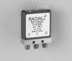
18 SMA -- SMA DIN.6/5.6 SPDT up to 4 GHz --- RAMSES Concept R Actuator terminal Connectors RF Solder Pins SMA up to 3 GHz SMA up to 8 GHz SMA 2.9 up to 26.5 GHz SMA 2.9 up to 4 GHz DIN.6/5.6 up to GHz Options 3 4 Type Failsafe Failsafe + I.C. Latching Latching + I.C. Latching + S.C.O.() Latching + S.C.O. + I.C.() Without option Positive common (2)(3) With suppression diodes () With suppression diodes and positive common (2)(3) TTL option Without TTL driver With TTL driver I.C. Indicator contact. S.C.O. Self Cut Off () Suppression diodes are already included in Self cut--off and TTL options (2) TTL option is not available with this option (3) Positive common must be specified only with Type 3, 4, 5 or 6 Actuator voltage 2 2 Vdc 3 28 Vdc GENERAL SPECIFICATIONS - RF PERFORMANCES Connectors Frequency range GHz SMA / SMA 2.9 SMA 2.9 DC - 3 / DC - 8 / DC DC - 4 DIN.6/5.6 DC -- DC DC DC Insertion Loss (max) db Isolation (min) db Impedance W V.S.W.R. (max) 5 75 Break Before Make Switching sequence GENERAL SPECIFICATIONS - ADDITIONAL SPECIFICATIONS Failsafe or Latching Operating mode Failsafe Actuator voltage (nominal) Vdc Coil resistance (±%) Operating current at 23 C W ma See Power Rating Chart page 9 Average power Peak power TTL INPUT kw High level Low level.5 ( ms, ) 2.2 to 5.5 V to.8 V W -- 3 V -- ma Indicator rating Switching time (max) Latching 2 ms 6 cycles for SMA & SMA 2.9 / 5 6 cycles for DIN.6/5.6 Life SMA, SMA 2.9 & DIN.6/5.6 Connectors Solder pins Actuator terminals Operating temperature range _C --4, +85 (--25, +7 for DIN.6 / 5.6 ) Storage temperature range _C --55, +85 (--4, +85 for DIN.6 / 5.6 ) 8

19 SMA -- SMA DIN.6/5.6 SPDT up to 4 GHz --- RAMSES Concept TYPICAL OUTLINE DRAWING SMA --- SMA 2.9 DIN.6 / 5.6 Connectors SMA SMA 2.9 DIN.6/5.6 A max ( mm )
20 N -- TNC -- BNC SPDT up to 2.4 GHz --- RAMSES Concept R Actuator terminal Connectors RF Solder Pins 5 D SUB N up to 3 GHz N up to 2.4 GHz BNC up to 3 GHz TNC up to 3 GHz TNC up to 2.4 GHz Options 3 4 Type Failsafe Failsafe + I.C. Latching Latching + I.C. Latching + S.C.O.() Latching + S.C.O. + I.C.() Without option Positive common (2)(3) With suppression diodes () With suppression diodes and positive common (2)(3) TTL option Without TTL driver With TTL driver () I.C. Indicator contact. S.C.O. Self Cut Off () Suppression diodes are already included in Self cut--off and TTL options (2) TTL option is not available with this option (3) Positive common must be specified only with Type 3, 4, 5 or 6 Actuator voltage 2 2 Vdc 3 28 Vdc GENERAL SPECIFICATIONS - RF PERFORMANCES Connectors Frequency range GHz N / TNC BNC DC - 3 / DC DC - 3 DC DC Insertion Loss (max) db Isolation (min) db Impedance W V.S.W.R. (max) 5 Break Before Make Switching sequence GENERAL SPECIFICATIONS - ADDITIONAL SPECIFICATIONS Failsafe or Latching Operating mode Failsafe Actuator voltage (nominal) Vdc Coil resistance (±%) Operating current at 23 C 28 W 34 ma 35 TTL INPUT kw High level Low level ( ms, ) 2.2 to 5.5 V to.8 V W -- 3 V -- ma Indicator rating Switching time (max) 2 See Power Rating Chart page 9 Average power Peak power Latching 2 ms 5 6 cycles Life N -- TNC -- BNC Connectors Solder pins or D SUB 9 PINS Actuator terminals Operating temperature range _C --4, +85 Storage temperature range _C --55, +85 2

21 N -- TNC -- BNC SPDT up to 2.4 GHz --- RAMSES Concept TYPICAL OUTLINE DRAWING BNC --- N --- TNC with solder pins BNC --- N --- TNC with D---Sub connector Connectors N BNC TNC A max (mm)
22 SMA -- SMA DIN.6/5.6 SPDT up to 4 GHz --- RAMSES Concept Low consumption current & small size R Actuator terminal Connectors RF Vdc 3 28 Vdc SMA up to 3 GHz SMA up to 8 GHz SMA 2.9 up to 26.5 GHz SMA 2.9 up to 4 GHz DIN.6/5.6 up to GHz Type Failsafe 3 Latching GENERAL SPECIFICATIONS - RF PERFORMANCES Connectors Frequency range GHz V.S.W.R. (max) SMA / SMA 2.9 SMA 2.9 DIN.6/5.6 DC - 3 / DC - 8 / DC DC - 4 DC -- DC DC DC Insertion Loss (max) db Isolation (min) db Impedance W Break Before Make Switching sequence GENERAL SPECIFICATIONS - ADDITIONAL SPECIFICATIONS Failsafe or Latching Operating mode Failsafe Actuator voltage (nominal) Vdc Coil resistance (±%) Operating current at 23 C Latching W 75 ma See Power Rating Chart page 9 Average power Peak power kw Switching time (max) ms.5 ( ms, ) cycles Life SMA, SMA 2.9 & DIN.6/5.6 Connectors Solder pins Actuator terminals Operating temperature range _C --4, +85 (--25, +7 for DIN.6 / 5.6 ) Storage temperature range _C --55, +85 (--4, +85 for DIN.6 / 5.6 ) 22

23 SMA -- SMA DIN.6/5.6 SPDT up to 4 GHz --- RAMSES Concept TYPICAL OUTLINE DRAWING SMA --- SMA DIN.6/5.6 Connectors SMA SMA 2.9 DIN.6/5.6 A max (mm)
24 TECHNICAL INFORMATION SCHEMATICS OF ELECTRICAL CONNECTION FOR SPDT FAILSAFE WITHOUT OPTION R WITH INDICATOR CONTACT R WITH SUPPRESSION DIODES R WITH SUPPRESSION DIODES AND INDICATOR CONTACT R WITH TTL DRIVER R WITH TTL DRIVER AND INDICATOR CONTACT R
25 TECHNICAL INFORMATION SCHEMATICS OF ELECTRICAL CONNECTION FOR SPDT LATCHING WITHOUT OPTION R WITH INDICATOR CONTACT R WITH SUPPRESSION DIODES R WITH SUPPRESSION DIODES AND INDICATOR CONTACT R WITH TTL DRIVER R WITH TTL DRIVER AND INDICATOR CONTACT R
26 TECHNICAL INFORMATION SCHEMATICS OF ELECTRICAL CONNECTION FOR SPDT LATCHING WITH CUT-- OFF R WITH CUT-- OFF AND INDICATOR CONTACT R WITH CUT-- OFF AND TTL R WITH CUT-- OFF, TTL AND INDICATOR CONTACT R WITH POSITIVE COMMON, NO OPTION R WITH POSITIVE COMMON AND INDICATOR CONTACT R
27 TECHNICAL INFORMATION SCHEMATICS OF ELECTRICAL CONNECTION FOR SPDT LATCHING WITH POSITIVE COMMON AND SUPPRESSION DIODES R WITH POSITIVE COMMON, SUPRESSION DIODES AND INDICATOR CONTACT R WITH POSITIVE COMMON AND CUT-- OFF R WITH POSITIVE COMMON, CUT-- OFF AND INDICATOR CONTACT R PIN IDENTIFICATION Pin Type Failsafe Failsafe + I C. Failsafe + TTL Failsafe + I.C. + TTL + + E E Gnd Gnd 4 Latching Latching + Cut---off Latching + I.C. Latching + I.C. + Cut---off Latching + Cut---off Latching + Cut---off + I.C. Latching + TTL + I.C E2 --- or or + E ---C Gnd VCC E2 E Gnd VCC VCC VCC +C ---C +C D--- SUB 9 pins NO NC C 2NO NC C 2 C 2 C bottom view 27
28 SMA TERMINATED SPDT and DP3T up to 8 GHz --- RAMSES Concept R Actuator terminal Connectors RF 3 SMA up to 3 GHz 4 SMA up to 8 GHz Solder Pins Type Options Failsafe Failsafe + I.C. Latching Latching + I.C. Latching + S.C.O.() Latching + S.C.O. + I.C.() Normally Open Normally Open + I.C. Without option Positive common (2)(4) With suppression diodes () With suppression diodes and positive common (3)(4) TTL and termination options Actuator voltage 2 2 Vdc 3 28 Vdc I.C. S.C.O. () (2) (3) (4) Indicator contact. Self Cut Off Without TTL driver (DP3T) With TTL driver (DP3T) Terminated (internal termination) / Without TTL driver Terminated (internal termination) / With TTL driver Terminated (external termination) / Without TTL driver Terminated (external termination) / With TTL driver Suppression diodes are already included in Self Cut--off and TTL TTL option is not available with this option Self Cut--off and TTL options are not available with this option Positive common must be specified only with Type 3, 4, 5 or 6 GENERAL SPECIFICATIONS - RF PERFORMANCES Connectors Frequency range SMA GHz DC - 3 / DC - 8 DC V.S.W.R. (max) Insertion Loss (max) db Isolation (min) db Impedance W 5 Break Before Make Switching sequence GENERAL SPECIFICATIONS - ADDITIONAL SPECIFICATIONS Failsafe, Latching or Normally open Operating mode Failsafe Latching Normally open Actuator voltage (nominal) Vdc Coil resistance (±%) W Operating current at 23 C ma See Power Rating Chart page 9 Average power TTL INPUT Peak power High level Low level kw.5 ( ms, ) W -- 3 V -- ma Indicator rating Switching time (max) 2.2 to 5.5 V to.8 V ms 2 6 cycles for products with internal terminations 6 cycles for all other products Life SMA Connectors Solder pins Actuator terminals Operating temperature range _C --4, +85 Storage temperature range _C --55,

29 SMA DP3T up to 8 GHz --- RAMSES Concept TYPICAL OUTLINE DRAWING DP3T R R With internal terminations R R With external terminations R R
30 TECHNICAL INFORMATION SCHEMATICS OF ELECTRICAL CONNECTION FOR DP3T FAILSAFE WITHOUT OPTION R / R / R WITH INDICATOR CONTACT R / R / R WITH SUPPRESSION DIODES R / R R WITH SUPPRESSION DIODES AND INDICATOR CONTACT R / R / R WITH TTL DRIVER R / R / R WITH TTL DRIVER AND INDICATOR CONTACT R / R / R
31 TECHNICAL INFORMATION SCHEMATICS OF ELECTRICAL CONNECTION FOR DP3T NORMALLY OPEN WITHOUT OPTION R / R / R WITH INDICATOR CONTACT R / R / R WITH SUPPRESSION DIODES R / R / R WITH SUPPRESSION DIODES AND INDICATOR CONTACT R / R / R WITH TTL DRIVER R / R / R WITH TTL DRIVER AND INDICATOR CONTACT R / R / R
32 TECHNICAL INFORMATION SCHEMATICS OF ELECTRICAL CONNECTION FOR DP3T NORMALLY OPEN WITH POSITIVE COMMON, NO OPTION R / R / R WITH COMMON POSITIVE AND INDICATOR CONTACT R / R / R WITH POSITIVE COMMON AND SUPPRESSION DIODES R / R / R WITH POSITIVE COMMON, SUPRESSION DIODES AND INDICATOR CONTACT R / R / R LATCHING WITHOUT OPTION R / R / R WITH INDICATOR CONTACT R / R / R
33 TECHNICAL INFORMATION SCHEMATICS OF ELECTRICAL CONNECTION FOR DP3T LATCHING WITH SUPPRESSION DIODES R / R / R WITH SUPPRESSION DIODES AND INDICATOR CONTACT R / R / R WITH TTL DRIVER R / R / R WITH TTL DRIVER AND INDICATOR CONTACT R / R / R WITH CUT-- OFF R / R / R WITH CUT-- OFF AND INDICATOR CONTACT R / R / R
34 TECHNICAL INFORMATION SCHEMATICS OF ELECTRICAL CONNECTION FOR DP3T LATCHING WITH CUT-- OFF AND TTL R / R / R WITH CUT-- OFF, TTL AND INDICATOR CONTACT R / R / R WITH POSITIVE COMMON, NO OPTION R / R / R WITH POSITIVE COMMON AND INDICATOR CONTACT R / R / R WITH POSITIVE COMMON AND SUPPRESSION DIODES R / R / R WITH POSITIVE COMMON, SUPRESSION DIODES AND INDICATOR CONTACT R / R /R
35 TECHNICAL INFORMATION SCHEMATICS OF ELECTRICAL CONNECTION FOR DP3T LATCHING WITH POSITIVE COMMON AND CUT-- OFF R / R / R WITH POSITIVE COMMON, CUT-- OFF AND INDICATOR CONTACTS R / R / R PIN IDENTIFICATION Pin Type Failsafe Failsafe + I C Failsafe + TTL E Gnd VCC Failsafe + I.C. + TTL E Gnd VCC Latching Latching + Cut---off or+ +C ---C Latching + I.C. Latching + I.C. + Cut---off or+ +C ---C Latching + TTL. Latching + TTL + Cut---off E2 E Gnd VCC Latching + TTL.+ I.C. Latching + TTL + I.C. Cut---off E2 E Gnd VCC Normally Open N O + Cut---off or+ +C ---C N O + I.C. N O + I.C. + Cut---off or+ +C ---C N O + TTL. N O + TTL + Cut---off E2 E Gnd VCC N O + TTL.+ I.C. N O + TTL + I.C.+ Cut---off E2 E Gnd VCC NO NC C 2NO NC C 2 C 2 C 2 C 2 C 35
36 SMA -- SMA DIN.6/5.6 DPDT up to 4 GHz --- RAMSES Concept R Connectors RF Actuator terminal and fixing SMA up to 3 GHz SMA up to 8 GHz SMA 2.9 up to 26.5 GHz SMA 2.9 up to 4 GHz DIN.6/5.6 up to GHz Solder Pins with Bracket Solder Pins without Bracket DSUB with Bracket DSUB without Bracket Options Type Failsafe Failsafe + I.C. Latching Latching + I.C. Latching + S.C.O.() Latching + S.C.O. + I.C.() Without option Positive common (2)(4) With suppression diodes () With suppression diodes and positive common (3)(4) TTL option Actuator voltage Without TTL driver With TTL driver 2 2 Vdc 3 28 Vdc () (2) (3) (4) I.C. Indicator contact. S.C.O. Self Cut Off Suppression diodes are already included in Self cut--off and TTL TTL option is not available with this option Self Cut Off and TTL option are not available with this option Positive common must be specified only with Type 3, 4, 5 or 6 GENERAL SPECIFICATIONS - RF PERFORMANCES Connectors Frequency range GHz V.S.W.R. (max) SMA / SMA 2.9 SMA 2.9 DIN.6/5.6 DC - 3 / DC - 8 / DC DC - 4 DC -- DC DC DC Insertion Loss (max) db Isolation (min) db Impedance W Break Before Make Switching sequence GENERAL SPECIFICATIONS - ADDITIONAL SPECIFICATIONS Failsafe or Latching Operating mode Failsafe Latching Actuator voltage (nominal) Vdc Coil resistance (±%) W Operating current at 23 C ma See Power Rating Chart page 9 Average power Peak power TTL INPUT kw High level Low level 2.2 to 5.5 V to.8 V W -- 3 V -- ma Indicator rating Switching time (max).5 ( ms, ) ms cycles Life SMA, SMA 2.9, DIN.6/5.6 Connectors Solder pins or DSUB 9 pins Actuator terminals Operating temperature range _C --4, +85 (--25, +7 for DIN.6 / 5.6) Storage temperature range _C --55, +85 (--4, +85 for DIN.6 / 5.6) 36
 7.4 6.3.")
37 SMA -- SMA DIN.6/5.6 DPDT up to 4 GHz --- RAMSES Concept TYPICAL OUTLINE DRAWING SMA --- SMA DIN.6 / 5.6 with bracket SMA --- SMA DIN.6 / 5.6 without bracket Connectors SMA SMA 2.9 DIN.6/5.6 A max ( mm )
38 N -- TNC -- BNC DPDT up to 2.4 GHz --- RAMSES Concept R Connectors RF Actuator terminal and fixing N up to 3 GHz N up to 2.4 GHz BNC up to 3 GHz TNC up to 3 GHz TNC up to 2.4 GHz Solder Pins with Bracket Solder Pins without Bracket DSUB with Bracket DSUB without Bracket Options Type Failsafe Failsafe + I.C. Latching Latching + I.C. Latching + S.C.O.() Latching + S.C.O. + I.C.() Without option Positive common (2)(3) With suppression diodes () With suppression diodes and positive common (2)(3) TTL option Actuator voltage Without TTL driver With TTL driver 2 2 Vdc 3 28 Vdc () Suppression diodes are already included in Self cut--off and TTL options (2) TTL option is not available with this option (3) Positive common must be specified only with Type 3, 4, 5 or 6 I.C. Indicator contact. S.C.O. Self Cut Off GENERAL SPECIFICATIONS - RF PERFORMANCES Connectors Frequency range N / TNC GHz V.S.W.R. (max) BNC DC - 3 / DC DC - 3 DC DC Insertion Loss (max) db Isolation (min) db Impedance W 5 Break Before Make Switching sequence GENERAL SPECIFICATIONS - ADDITIONAL SPECIFICATIONS Failsafe or Latching Operating mode Failsafe Actuator voltage (nominal) Vdc Coil resistance (±%) Operating current at 23 C W ma See Power Rating Chart page 9 Average power Peak power TTL INPUT kw High level Low level.5 ( ms, ) 2.2 to 5.5 V to.8 V W -- 3 V -- ma Indicator rating Switching time (max) Latching 2 ms cycles Life N -- TNC --BNC Connectors Solder pins or DSUB 9 pins Actuator terminals Operating temperature range _C --4, +85 Storage temperature range _C --55,

39 N -- TNC -- BNC SPDT up to 2.4 GHz --- RAMSES Concept TYPICAL OUTLINE DRAWING N --- TNC --- BNC with bracket N --- TNC --- BNC without bracket Connectors N BNC TNC A max ( mm )
40 TECHNICAL INFORMATION SCHEMATICS OF ELECTRICAL CONNECTION FOR DPDT FAILSAFE WITHOUT OPTION R WITH INDICATOR CONTACT R WITH SUPPRESSION DIODES R WITH SUPPRESSION DIODES AND INDICATOR CONTACT R WITH TTL DRIVER R WITH TTL DRIVER AND INDICATOR CONTACT R
41 TECHNICAL INFORMATION SCHEMATICS OF ELECTRICAL CONNECTION FOR DPDT LATCHING WITHOUT OPTION R WITH INDICATOR CONTACT R WITH SUPPRESSION DIODES R WITH SUPPRESSION DIODES AND INDICATOR CONTACT R WITH TTL DRIVER R WITH TTL DRIVER AND INDICATOR CONTACT R
42 TECHNICAL INFORMATION SCHEMATICS OF ELECTRICAL CONNECTION FOR DPDT LATCHING WITH CUT-- OFF R WITH CUT-- OFF AND INDICATOR CONTACT R WITH CUT-- OFF AND TTL R WITH CUT-- OFF, TTL AND INDICATOR CONTACT R WITH POSITIVE COMMON, NO OPTION R WITH POSITIVE COMMON AND INDICATOR CONTACT R
43 TECHNICAL INFORMATION SCHEMATICS OF ELECTRICAL CONNECTION FOR DPDT LATCHING WITH POSITIVE COMMON AND SUPPRESSION DIODES R WITH POSITIVE COMMON, SUPRESSION DIODES AND INDICATOR CONTACT R WITH POSITIVE COMMON AND CUT-- OFF R WITH POSITIVE COMMON, CUT-- OFF AND INDICATOR CONTACT R PIN IDENTIFICATION D--- SUB 9 pins Pin Type Failsafe Failsafe + I C. Failsafe + TTL Failsafe + I.C. + TTL Latching Latching + Cut---off Latching + I.C. Latching + I.C. + Cut---off Latching + Cut---off Latching + Cut---off + I.C. Latching + TTL + I.C. + + E E E ---2 or or +2 E2 E E Gnd Gnd +C ---C +C 4 VCC VCC ---C Gnd VCC Gnd VCC C 2 C 2 C 2 C bottom view 43
44 SMA -- SMA DIN.5 / 5.6 SPnT up to 4 GHz --- RAMSES Concept R Models Actuator terminal 3 Without 5 W termination 4 With 5 W termination Solder Pins 5 DSUB Connector RF Options SMA up to 3 GHz SMA up to 8 GHz SMA 2.9 up to 26.5 GHz (4) SMA 2.9 up to 4 GHz (4) DIN.6/5.6 up to GHz (4) Without option Positive common (2) Compatible TTL driver() With suppression diodes With suppression diodes and positive common (2) 8 BCD driver TTLcompatible()(3) Type Normally open Normally open + I.C. Latching Latching + I.C. Latching + S. C. O.()(4) Latching + S. C. O. + I.C.()(4) Latching + S. C. O. +A.R.() Latching + S. C. O.+ I.C.+ A.R. () Number of positions Actuator voltage (2) 2 2 Vdc 3 28 Vdc I.C. Indicator contact. S.C.O. Self Cut Off A.R. Automatic Reset () (2) (3) (4) 3 Positions 4 Positions 5 Positions 6 Positions 7 Positions 8 Positions 9 Positions Positions Positions 2 Positions These models are already equiped with suppression diodes. Standard products are equiped with common minus. Latching BCD driver enables also a manual reset through driver code. Available only up to 6 positions, and without 5 Ohms termination -- Latching models have a RESET pin which commands the reset of all positions. This command should be used before switching from one position to another. If not, two positions will be set at the same time. Note During the RESET operation the current is Setting current x number of positions. -- Latching models with AUTOMATIC RESET are available; these products have an internal SET/RESET circuit which automatically set the desired position and reset the non--selected positions. This option simplifies the use of latching switches by suppressing the RESET command in switching sequence. For example During the AUTOMATIC RESET operation, a 28V, 4 positions switch has temporarily a consumption of 25 ma, during 4 ms maximum only. AVAILABILITY OF OPTIONS ACCORDING TO BOTH TYPE AND NUMBER OF POSITIONS Type Number of positions Available options or 3 to or 3 3 to to to to 2 Not Available 3 to or 5 8 or 9 44
45 SMA -- SMA DIN.5 / 5.6 SPnT up to 4 GHz --- RAMSES Concept GENERAL SPECIFICATIONS - RF PERFORMANCES Connectors SMA Number of positions Frequency q y range g 3 to 6 GHz 7 and 8 DC--3 /DC -- 8 DC--3 /DC -- 8 DC DC Insertion Loss (max) db Isolation (min) db V.S.W.R. (max) Connectors SMA Number of positions Frequency q y range g 9 and GHz V.S.W.R. (max) and 2 DC - 3 / DC - 8 DC--3 /DC DC DC Insertion Loss (max) db Isolation (min) db Connectors DIN.6 / 5.6 SMA to 6 3 to 6 Number of positions Frequency q y range g GHz DC - DC / DC -- 4 DC DC V.S.W.R. (max) Insertion Loss (max) db Isolation (min) db GENERAL SPECIFICATIONS - ADDITIONAL SPECIFICATIONS Normally open or Latching Operating mode Normally open Latching Actuator voltage (nominal) Vdc 2 28 Operating current at 23 C ma See table page 49 See Power Rating Chart page 9 Average power kw Peak power.5 ( ms, ) High level Low level TTL INPUT 2.2 to 5.5 V ( TTL option ) / 3.5 to 5.5 ( BCD option ) to.8 V ( TTL option ) / to.5 V ( BCD option ) W -- 3 V -- ma Indicator rating ms Switching time (max) 5 (for automatic reset models, SP3T to SP6T 4 ms, SP7T to SP2T 5 ms) Life SP3 to 6T SMA SMA 2.9 /.6/5.6 R573 serie 5 6 cycles per way 2 6 cycles per way R574 serie 2 6 cycles per way 2 6 cycles per way SP7 to 2T SMA, SMA 2.9 or.6/5.6 Connectors Solder pins or DSUB Actuator terminals Operating temperature range _C --4, +85 (SMA & SMA 2.9) /--25,+7 (DIN.6/5.6) Storage temperature range _C --55, +85 (SMA & SMA 2.9) / --4, +85 (DIN.6/5.6) Impedance p For terminated models Switching sequence W SMA & SMA 2.9 DIN.6/ W termination ±5% Watt per termination 3 W total power handling per switch Break Before Make 45

46 SMA -- SMA DIN.5 / 5.6 SPnT up to 4 GHz --- RAMSES Concept TYPICAL OUTLINE DRAWING 3 to 6 positions NOT TERMINATED B 3 to 6 positions NOT TERMINATED A A B 6.5 with D Sub B 55 with solder pins SOLDER PINS Type or with option 2 or 8 Type 2 or 3 with option or 8 Type or 9 with option or 8 D Sub all models SOLDER PINS Type or with option or 4 Type 2 or 3 with option or Connectors SMA SMA 2.9 DIN.6/5.6 A max ( mm )
47 SMA SPnT up to 8 GHz --- RAMSES Concept TYPICAL OUTLINE DRAWING 3 to 6 positions TERMINATED 7 to 2 positions TERMINATED or NOT Type or 3 with option or 4 A 46.5 Maxi with solder pins A 6.5 Maxi with D Sub Type or 3 with option 2 or 8 A 55.5 Maxi with solder pins A 6.5 Maxi with D Sub Type or 9 with option or 8 Type Nb of positions Type or 3 with option or Type or 3 with option 2 or 8 Type or 9 with option or E maxi 5 with solder pins 66 with D Sub 5 with solder pins 66 with D Sub B dia. C dia. D dia
48 N -- TNC -- BNC STANDARD SPnT up to 2.4 GHz --- RAMSES Concept R Models Actuator terminal 3 Without 5 W termination 4 With 5 W termination Solder Pins 5 DSUB Connector RF Options N up to 3 GHz N up to 2.4 GHz BNC up to 3 GHz (4) TNC up to 3 GHz (4) TNC up to 2.4 GHz (4) Without option Positive common (2) Compatible TTL driver() With suppression diodes With suppression diodes and positive common (2) 8 BCD driver TTLcompatible()(3) Type Normally open Normally open + I.C. Latching Latching + I.C. Latching + S. C. O.() Latching + S. C. O. + I.C.() Latching + S. C. O. +A.R.() Latching + S. C. O.+ I.C.+ A.R. () Number of positions Actuator voltage (2) 2 2 Vdc 3 28 Vdc I.C. Indicator contact. S.C.O. Self Cut Off A.R. Automatic Reset () (2) (3) (4) 3 Positions 4 Positions 5 Positions 6 Positions 7 Positions 8 Positions 9 Positions Positions Positions 2 Positions These models are already equiped with suppression diodes. Standard products are equiped with common minus. Latching BCD driver enables also a manual reset through driver code. Available only up to 6 positions. -- Latching models have a RESET pin which commands the reset of all positions. This command should be used before switching from one position to another. If not, two positions will be set at the same time. Note During the RESET operation the current is Setting current x number of positions. -- Latching models with AUTOMATIC RESET are available; these products have an internal SET/RESET circuit which automatically set the desired position and reset the non--selected positions. This option simplifies the use of latching switches by suppressing the RESET command in switching sequence and reducing the operating current consuption. For example During the AUTOMATIC RESET operation, a 28V, 4 positions switch has temporarily a consumption of 25 ma, during 4 ms maximum only ( See page 56 ). AVAILABILITY OF OPTIONS ACCORDING TO BOTH TYPE AND NUMBER OF POSITIONS Type Number of positions Available options or 3 to or 3 3 to to to to 2 Not Available 3 to or 5 8 or 9 48
 db.2.35.5.3.5.5. Isolation (min) db 8 7 6 8 7 7 6 V.S.W.R.")
49 N -- TNC -- BNC SPnT up to 2.4 GHz --- RAMSES Concept GENERAL SPECIFICATIONS - RF PERFORMANCES Connectors N - BNC - TNC Number of positions Frequency q y range g 3 to 6 GHz 7 to DC and 2 DC - 8 DC - 8 DC DC DC Insertion Loss (max) db Isolation (min) db V.S.W.R. (max) GENERAL SPECIFICATIONS - ADDITIONAL SPECIFICATIONS Normally open or Latching Operating mode Normally open Latching Actuator voltage (nominal) Vdc 2 28 Operating current at 23 C ma See table below See Power Rating Chart page 9 Average power kw Peak power.5 ( ms, ) High level Low level TTL INPUT 2.2 to 5.5 V ( TTL option ) / 3.5 to 5.5 V ( BCD option ) to.8 V ( TTL option ) / to.5 V ( BCD option ) W -- 3 V -- ma Indicator rating ms Switching time (max) Life SP3 to 6T 5 (for automatic reset models, SP3T to SP6T 4 ms, SP7T to SP2T 5 ms) R573 serie 5 6 cycles per way R574 serie 2 6 cycles per way 2 6 cycles per way SP7 to 2T N, TNC, BNC Connectors Solder pins or DSUB Actuator terminals Operating temperature range _C --4, +85 Storage temperature range _C --55, +85 Impedance 5 W 5 W termination ±5% Watt per termination 3 W total power handling per switch For terminated models Break Before Make Switching sequence Operating current at 23 C (ma) SPnT LATCHING 2 V 28 V manual reset automatic reset manual reset automatic reset SP 3 to 4 T 32 x n x n 25 SP 5 to 8 T 32 x n x n 375 SP 9 to 2 T 32 x n x n 5 n = number of ways 49
50 N -- TNC -- BNC TYPICAL OUTLINE DRAWING Type Nb of positions 3 to 6 Type,, 2 or 3 with option,,,, 3 or 4 7 to 8 9 to to 2 Type,, 2 or 3 with option 2 or 8 Type 4, 5, 8 or 9 with option,, 2, 3, 4 or 8 3 to 6 7 to 8 9 to to 2 A 56 MAX with Solder Pins 7 MAX with D Sub 66 MAX with Solder Pins 7 MAX with D Sub B dia. C dia. D dia. E F holes M4/6_ N holes M4/9_ BNC holes M4/72_ TNC holes M4/9_ holes M4/6_ holes M4/9_ holes M4/72_ holes M4/9_ 5
51 TECHNICAL INFORMATION SCHEMATICS OF ELECTRICAL CONNECTION FOR SPnT NORMALLY OPEN WITHOUT OPTION R / R WITH INDICATOR CONTACT R / R WITH SUPPRESSION DIODES R / R WITH SUPPRESSION DIODES AND INDICATOR CONTACT R / R WITH TTL DRIVER R / R WITH TTL DRIVER AND INDICATOR CONTACT R / R
52 TECHNICAL INFORMATION SCHEMATICS OF ELECTRICAL CONNECTION FOR SPnT NORMALLY OPEN WITH BCD DRIVER, TTL COMPATIBLE / R WITH BCD DRIVER, TTL COMPATIBLE AND INDICATOR CONTACT / R WITH POSITIVE COMMON R / R WITH POSITIVE COMMON AND INDICATOR CONTACT R / R WITH POSITIVE COMMON AND SUPPRESSION DIODES R / R WITH POSITIVE COMMON, SUPPRESSION DIODES AND INDICATOR CONTACT R / R
53 TECHNICAL INFORMATION SCHEMATICS OF ELECTRICAL CONNECTION FOR SPnT LATCHING WITHOUT OPTION R / R WITH INDICATOR CONTACT R / R WITH SUPPRESSION DIODES R / R WITH SUPPRESSION DIODES AND INDICATOR CONTACT R / R WITH TTL DRIVER R / R WITH TTL DRIVER AND INDICATOR CONTACT R / R
54 TECHNICAL INFORMATION SCHEMATICS OF ELECTRICAL CONNECTION FOR SPnT LATCHING WITH CUT-- OFF R / R WITH CUT-- OFF AND INDICATOR CIRCUIT R / R WITH CUT-- OFF AND AUTO RESET R / R WITH CUT-- OFF, AUTO RESET AND INDICATOR CONTACT R / R WITH TTL DRIVER AND CUT-- OFF R / R WITH TTL DRIVER, CUT-- OFF AND INDICATOR CONTACT R / R
55 TECHNICAL INFORMATION SCHEMATICS OF ELECTRICAL CONNECTION FOR SPnT LATCHING WITH TTL DRIVER, CUT-- OFF AND AUTO RESET R / R WITH TTL DRIVER, CUT-- OFF, AUTO RESET AND INDICATOR CONTACT R / R WITH CUT-- OFF, FORCED R AUTO RESET, BCD DRIVER, TTL COMPATIBLE R / R WITH CUT-- OFF, FORCED OR AUTO RESET, BCD DRIVER, TTL COMPATIBLE AND INDICATOR CONTACT R / R WITH POSITIVE COMMON R / R WITH POSITIVE COMMON AND INDICATOR CONTACT R / R
56 TECHNICAL INFORMATION SCHEMATICS OF ELECTRICAL CONNECTION FOR SPnT LATCHING WITH POSITIVE COMMON AND SUPPRESSION DIODES R / R WITH POSITIVE COMMON, SUPPRESSION DIODES AND INDICATOR CONTACT R / R PIN IDENTIFICATION Due to the numerous various configurations, it isn t possible to introduce Pin Identification it this catalog, ask our sales department for the needed Technical Data Sheet, the requested information is included in all TDS. Note about AUTOMATIC RESET This control circuit is used in multithrow latching switches. It s an electronic matrix that interconnects all the reset coils of each position. Used in conjunction with the cut--off circuitry, it allows the switch to reset from the previous closed RF way upon selection of a new RF one. The current with this option is the total current of 2 or 3 reset coils in the same time. Without Automatic Reset circuitry, all reset coils are connected at all times, so the total current can be excessive. --C volt on --C 28 volts on + 56

57 ACCESSORIES A printed circuit board interface connector ( PCBIC ) has been designed for easy mounting on actuator solder pins. It can be supplied separately for all switches SPDT, DPDT, DP3T, SPnT Model Range PCBIC P/N SPDT R57 R5999 DPDT R577 R5999 DP3T R585 R to 6 position R573 / R574 R to 8 position R573 / R574 R to position R573 / R574 R5999 to 2 position R573 / R574 R59992 SPnT R5999 R59996 R59998 R5999 R
58

 5 max 245 max Voltage ( Vdc ) 2 --- 32 2 --- 3 Current (")

 Voltage ( Vdc ) max 2 --- 32 4 max 2 --- 3 Current ( ma )")
59 SPACE RADIALL HI---REL SPACE QUALIFIED are designed and built to satisfy the stringent demands of space environment via intensive manufacturing and quality procedures, such as European Space Agency ESA / SCC. SPDT or S Type SWITCH DC GHz with SMA connectors DC GHz with TNC Connectors LATCHING with Telemetry Connectors SMA TNC Mass ( g ) 5 max 245 max Voltage ( Vdc ) Current ( ma ) max 26 max Multipactor GHz 23 GHZ DPDT or C Type SWITCH DC GHz with SMA connectors LATCHING with Telemetry Mass 5 g max Voltage V DC Current ma Multipactor GHz DP3T SWITCH DC GHz with SMA connectors DC GHz with TNC Connectors LATCHING with Telemetry Connectors SMA TNC Mass ( g ) Voltage ( Vdc ) max max Current ( ma ) max 26 max Multipactor GHz 8 GHZ T Type SWITCH DC GHz with SMA connectors RANDOM or SEQUENTIAL ACTUATOR with Telemetry Type Sequential Random Mass ( g ) 4 max 5 max Voltage ( Vdc ) Current ( ma ) 4 max 35 max Multipactor 2 3 GHz 2 3 GHZ 59


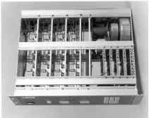
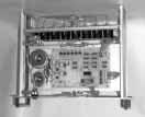
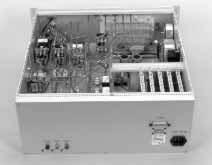
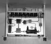
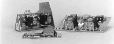
60 SWITCHING NETWORKS As, one of the worldwide leader in the design and development of coaxial connectors, RF and microwave coaxial cables and passive components, RADIALL is now applying its expertise to the developement of switching network product line that offers Standard or Customized solutions to its customers. Switching network applications include Automatic Test Equipment, Environmental or Laboratory Test Equipment improve the reliability and reduce the cost of testing by providing automatic sequences of RF test, with multiple Inputs and Outputs. Designed for Microwave and RF test applications in the DC--- 4 GHz frequency range, RADIALL switching networks allows the connection of each selected Input to any selected Output port. RADIALL switches, with their already acknowledged long life (2 to cycles), are perfectly suited for Switching Networks. RADIALL Switching Networks are packaged in 9 rack---mountable enclosure and provide various remote interfaces (RS 232, IEEE488 or GPIB,...). Specific package and remote controller can be designed on request. TYPICAL SCHEMATIC of SWITCHING NETWORK Microwave Test Instruments MICROWAVE SWITCHING MATRIX Device Under Test CONTROLLER IEEE488 / RS 232 /... POWER SUPPLIES 22 V / DC / 5 Hz or 6 Hz SOME EXEMPLES OF CUSTOM SWITCHING NETWORKS 4 X 4 Network Switching for Automatic Test Equipment 6
61
62
RAMSES SERIES R 570 PART NUMBER SELECTION. SPDT up to 18 GHz. Our Most Important Connection is with You. N - TNC - BNC
 SPDT up to 18 GHz PART NUMBER SELECTION Frequency Range: 0: N up to 3 GHz 1: N up to 12.4 GHz 2: BNC up to 3 GHz 5: TNC up to 3 GHz 6: TNC up to 12.4 GHz D: TNC up to 18 GHz Type: 1: Failsafe 2: Failsafe
Coaxial switching products
 Coaxial switching products Technical training B BARBE RADIALL IDA April 2010 Updated February 2011 Summary Coaxial line Switching sequence on basic product : SPDT - Break Before Make / Make Before Break
Standard Custom Electro-Mechanical Switches
 DC-26.5 GHz, SMA DP2T Series 136 Trsfer Switch RF Performce Freq. Rge (GHz) DC-3 3-8 8-12.4 12.4-18 18-26.5 VSWR (max.) 1.2 1.3 1.4 1.5 1.7 Insertion Loss (db max.) Isolation (db min.) Additional Specifications
PAGE 1/12 ISSUE SERIES DP3T/SPDT PART NUMBER R595 XXX XXX
 PAGE 1/12 ISSUE 22-06-2018 SERIES DP3T/SPDT PART NUMBER R595 XXX XXX DP3T-SPDT Coaxial Switches DC to 6 GHz, DC to 20 GHz, DC to 26.5 GHz, DC to 40 GHz Radiall s PLATINUM SERIES switches are optimised
Standard Custom Electro-Mechanical Switches
 Introduction Power Monitors DC-10 GHz, Type N d TNC SP7T-SP8T Series 073-083 RF Performce Freq. Rge (GHz) DC-3 3-8 8-10 VSWR (max.) 1.2 1.35 1.5 Insertion Loss (db max.) Isolation (db min.) Additional
Standard Custom Electro-Mechanical Switches
 Power Monitors DC-26.5 GHz, SMA SP3T-SP6T Series 030-060 RF Performce Freq. Rge (GHz) DC-3 3-8 8-12.4 12.4-18 18-26.5 VSWR (max.) 1.2 1.3 1.4 1.5 1.8 Insertion Loss (db max.) Isolation (db min.) 0.2 0.3
Series CCS-37K/CS-37K Miniature DC 36 GHz Latching TRANSFER Coaxial Switch
 PART NUMBER CCS-37K CS-37K DESCRIPTION Commercial Latching TRANSFER, DC-36GHz Elite Latching TRANSFER, DC-36GHz The CCS-37K/CS-37K is a long-life high performance transfer switch designed for use in 50
Series CCT-59S/CT-59S Multi-Throw DC-26.5 GHz Latching Coaxial Switch
 PART NUMBER CCT-59S CT-59S DESCRIPTION Commercial Latching Multi-throw, DC-26.5GHz Elite Latching Multi-throw, DC-26.5GHz The CCT-59S/CT-59S is an Internally Terminated broadband, multi-throw, electromechanical
Series CCRT-33S/CRT-33S Internal 50Ω Termination DC 18 GHz/DC-22 GHz Latching SPDT Coaxial Switch
 COAX SWITCHES Series CCRT-33S/CRT-33S PART NUMBER CCRT-33S CRT-33S DESCRIPTION Commercial Latching SPDT, DC-18GHz, Internal 50Ω Termination Elite Latching SPDT, DC-22GHz, Internal 50Ω Termination The CCRT-33S/CRT-33S
Series CCR-39S/CR-39S Multi-Throw DC-18 GHz/DC-22 GHz Latching Coaxial Switch
 PART NUMBER CCR-39S CR-39S DESCRIPTION Commercial Latching Multi-throw, DC-8GHz Elite Latching Multi-throw, DC-22GHz The CCR-39S/CR-39S is a broadband, multi-throw, electromechanical coaxial switch designed
Series CCS-19 Multi-Throw DC-2 GHz Latching Coaxial Switch
 PART NUMBER CCS-19 CS-19 DESCRIPTION Commercial Latching Multi-throw, DC-2GHz, with N or TNC connectors Elite Latching Multi-throw, DC-2GHz, with N or TNC connectors The CCS-19/CS-19 is a broadband, multi-throw,
Series CCS-47/CS-47 High Power DC 12 GHz Failsafe TRANSFER Coaxial Switch
 COAX SWITCHES Series CCS-47/CS-47 PART NUMBER CCS-47 CS-47 DESCRIPTION Commercial Failsafe TRANSFER, DC-GHz Elite Failsafe TRANSFER, DC-GHz The CCS-47/CS-47 is a long-life high performance transfer switch
Series CCT-38S Multi-Throw DC 12 GHz, SP7T & SP8T Normally Open Coaxial Switch
 COAX SWITCHES Series CCT-38S PART NUMBER CCT-38S DESCRIPTION Commercial Normally Open Multi-throw, DC-12 GHz The CCT-38S is a broadband, multi-throw, electromechanical coaxial switch designed to switch
Series CCS-37S/CS-37S Miniature DC 18 GHz Failsafe TRANSFER Coaxial Switch
 COAX SWITCHES Series CCS-37S/CS-37S PART NUMBER CCS-37S CS-37S DESCRIPTION Commercial Failsafe TRANSFER, DC-8GHz Elite Failsafe TRANSFER, DC-8GHz The CCS-37S/CS-37S is a long-life high performance transfer
Series CCT-58S/CT-58S Multi-Throw DC-26.5 GHz Normally Open Coaxial Switch
 COAX SWITCHES Series CCT-58S/CT-58S PART NUMBER CCT-58S CT-58S DESCRIPTION Commercial Normally Open Multi-throw, DC-26.5GHz Elite Normally Open Multi-throw, DC-26.5GHz The CCT-58S/CT-58S is an internally
Series H-47N DC up to 12 GHz Latching Transfer Space Grade Coaxial Switch
 COAX SWITCHES Series H-47N PART NUMBER H-47N DESCRIPTION Space Grade Latching Transfer, DC up to 12GHz Teledyne Coax Switches H-47N Series RF Coaxial Switch is a Commercial Off-The Shelf (COTS) product
433 & 443 Series INTELLIGENT RELAY SP3T & SP4T IN-LINE Multithrow Switches
 433 & 443 Series INTELLIGENT RELAY SP3T & SP4T IN-LINE Multithrow Switches Available with two types of internal drive electronics (Binary Decoding or MOSFET Pulse Latching), these SP3T and SP4T IN-LINE
Series CCP-32N Low PIM DC 3 GHz Latching SPDT Coaxial Switch
 COAX SWITCHES Series CCP-32N PART NUMBER CCP-32N DESCRIPTION Commercial Latching SPDT, DC-3GHz, Low PIM These switches are designed to have extremely low passive intermodulation for use in narrow bandwidth
PAGE 1/6 ISSUE SERIES Micro-SPDT PART NUMBER R516 XXX 10X. (All dimensions are in mm [inches]) R 516 _ 1 0 _
![PAGE 1/6 ISSUE SERIES Micro-SPDT PART NUMBER R516 XXX 10X. (All dimensions are in mm [inches]) R 516 _ 1 0 _](/thumbs/96/127769340.jpg "PAGE 1/6 ISSUE SERIES Micro-SPDT PART NUMBER R516 XXX 10X. (All dimensions are in mm [inches]) R 516 _ 1 0 _") PAGE 1/6 ISSUE 15-10-18 SERIES Micro-SPDT PART NUMBER R516 XXX 10X R516 series: the RAMSES concept merges with the SLIM LINE technology, breaking up the frequency limits of SMT switches : - FULL SMT TECHNOLOGY
PAGE 1/6 ISSUE 15-10-18 SERIES Micro-SPDT PART NUMBER R516 XXX 10X R516 series: the RAMSES concept merges with the SLIM LINE technology, breaking up the frequency limits of SMT switches : - FULL SMT TECHNOLOGY
Series CCP-47N Low PIM DC 3 GHz Latching TRANSFER Coaxial Switch
 COAX SWITCHES Series CCP-47N PART NUMBER CCP-47N DESCRIPTION Commercial Latching TRANSFER, DC-3GHz, Low PIM These switches are designed to have extremely low passive intermodulation for use in narrow bandwidth
Series CCRT-33S/CRT-33S Internal 50Ω Termination DC 18 GHz/DC-22 GHz Failsafe SPDT Coaxial Switch
 COAX SWITCHES Series CCRT-33S/CRT-33S PART NUMBER CCRT-33S CRT-33S DESCRIPTION Commercial Failsafe SPDT, DC-18GHz, Internal 50Ω Termination Elite Failsafe SPDT, DC-22GHz, Internal 50Ω Termination The CCRT-33S/CRT-33S
Series CCS-32/CS-32 High Power DC 12 GHz Failsafe SPDT Coaxial Switch
 PART NUMBER CCS-32 CS-32 DESCRIPTION Commercial Failsafe SPDT, DC-2GHz Elite Failsafe SPDT, DC-2GHz The CCS-32/CS-32 is a broadband, SPDT, electromechanical, coaxial switch designed to switch a microwave
Series CCT-59S Multi-Throw DC-18 GHz, SP7T & SP8T Latching Coaxial Switch, Internal 50Ω Termination
 COAX SWITCHES Series CCT-59S PART NUMBER CCT-59S DESCRIPTION Commercial Latching Multi-throw, DC-18GHz The CCT-59S is a broadband, multi-throw, electromechanical coaxial switch designed to switch a microwave
Series CCT-58S/CT-58S Multi-Throw DC-26.5 GHz Normally Open Coaxial Switch
 COAX SWITCHES Series CCT-58S/CT-58S PART NUMBER CCT-58S CT-58S DESCRIPTION Commercial Normally Open Multi-throw, DC-26.5GHz Elite Normally Open Multi-throw, DC-26.5GHz The CCT-58S/CT-58S is an internally
Series CCS-37S/CS-37S Miniature DC 18 GHz Latching TRANSFER Coaxial Switch
 COAX SWITCHES Series CCS-37S/CS-37S PART NUMBER CCS-37S CS-37S DESCRIPTION Commercial Latching TRANSFER, DC-8GHz Elite Latching TRANSFER, DC-8GHz The CCS-37S/CS-37S is a long-life high performance transfer
Series CCT-38S/CT-38S Multi-Throw DC 18 GHz/DC-22 GHz Normally Open Coaxial Switch
 COAX SWITCHES Series CCT-38S/CT-38S PART NUMBER CCT-38S CT-38S DESCRIPTION Commercial Normally Open Multi-throw, DC-18GHz Elite Normally Open Multi-throw, DC-22GHz The CCT-38S/CT-38S is an internally terminated,
Series H-33S DC up to 26.5 GHz Latching SPDT Space Grade Coaxial Switch
 COAX SWITCHES Series H-33S PART NUMBER H-33S DESCRIPTION Space Grade Latching SPDT, Teledyne Coax Switches H-33S Series RF Coaxial Switch is a Commercial Off-The Shelf (COTS) product suitable for high
TITANIUM SERIES R 51 PART NUMBER SELECTION. High Performance Multiport Switches. Our Most Important Connection is with You.
 PART NUMBER SELECTION Models: 2: Without 50 Ω terminations 4: With 50 Ω terminations RF Connectors: 3: SMA up to 6 GHz 4: SMA up to 20 GHz F: SMA up to 26.5 GHz 8: SMA 2.9 up to 40 GHz (1) Radiall s TITANIUM
Series CCRT-53S/CRT-53S Internal 50Ω Termination DC-26.5 GHz Failsafe SPDT Coaxial Switch
 COAX SWITCHES Series CCRT-53S/CRT-53S PART NUMBER CCRT-53S CRT-53S DESCRIPTION Commercial Failsafe SPDT, DC-26.5GHz, Internal 5Ω Termination Elite Failsafe SPDT, DC-26.5GHz, Internal 5Ω Termination The
Series CCR-33S/CR-33S Miniature DC 18 GHz/DC-22 GHz Failsafe SPDT Coaxial Switch
 COAX SWITCHES Series CCR-33S/CR-33S PART NUMBER CCR-33S CR-33S DESCRIPTION Commercial Failsafe SPDT, DC-18GHz Elite Failsafe SPDT, DC-22GHz The CCR-33S/CR-33S is a broadband, SPDT, electromechanical, coaxial
Series CCS-47/CS-47 High Power DC 12 GHz Latching TRANSFER Coaxial Switch
 PART NUMBER CCS-47 CS-47 DESCRIPTION Commercial Latching TRANSFER, DC-GHz Elite Latching TRANSFER, DC-GHz The CCS-47/CS-47 is a long-life high performance transfer switch designed for use in 5 Ohms coaxial
SPACE COAXIAL SWITCHES
 SPace SECTION CONTENTS SECTION 6 GENERAL INFORMATION... 6-1 low power models... 6-2 to 6-9 HIGH power models... 6-10 to 6-15 RADIALL SPECIFICATIONS... 6-16 GENERAL INFORMATION / SPECIFICATIONS Radiall
Series CCRS-33S/CRS-33S Miniature DC 18 GHz Failsafe 2P3T Coaxial Switch
 COAX SWITCHES Series CCRS-33S/CRS-33S PART NUMBER CCRS-33S CRS-33S DESCRIPTION Commercial Failsafe 2P3T, DC-18GHz Elite Failsafe 2P3T, DC-18GHz The CCRS-33S/CRS-33S is a broadband, 2P3T, electromechanical
Series CCR-58S/CR-58S Multi-Throw DC 26.5 GHz Normally Open Coaxial Switch
 PART NUMBER CCR-58S CR-58S DESCRIPTION Commercial Normally Open Multi-throw, DC-6.5GHz Elite Normally Open Multi-throw, DC-6.5GHz The CCR-58S/CR-58S is a broadband, multi-throw, electromechanical coaxial
FMSW6097 DATA SHEET. SPDT Failsafe Electro-Mechanical Relay Switch From DC to 26.5 GHz, 20 Watts with TTL, Diodes, Indicators, SMA.
 SPDT Failsafe Electro-Mechanical Relay Switch From DC to 26.5 GHz, 20 Watts with TTL, Diodes, Indicators, SMA The FMSW6097 is an SPDT Electromechanical Relay Switch that operates over a wide frequency
Series CCRS-53S/CRS-53S Miniature DC 26.5 GHz Failsafe 2P3T Coaxial Switch
 COAX SWITCHES Series CCRS-53S/CRS-53S PART NUMBER CCRS-53S CRS-53S DESCRIPTION Commercial Failsafe 2P3T, DC-26.5GHz Elite Failsafe 2P3T, DC-26.5GHz The CCRS-53S/CRS-53S is a broadband, 2P3T, electromechanical
Series CCRS-53S/CRS-53S Miniature DC 26.5 GHz Latching 2P3T Coaxial Switch
 COAX SWITCHES Series CCRS-53S/CRS-53S PART NUMBER CCRS-53S CRS-53S DESCRIPTION Commercial Latching 2P3T, DC-26.5GHz Elite Latching 2P3T, DC-26.5GHz The CCRS-53S/CRS-53S is a broadband, 2P3T, electromechanical
Series CCR-33K/CR-33K Miniature DC 33.5 GHz Failsafe SPDT Coaxial Switch
 PART NUMBER CCR-33K CR-33K DESCRIPTION Commercial Failsafe SPDT, DC-33.5GHz Elite Failsafe SPDT, DC-33.5GHz The CCR-33K/CR-33K is a broadband, SPDT, electromechanical, coaxial switch designed to switch
Series CCR-53S/CR-53S Miniature DC 26.5 GHz Latching SPDT Coaxial Switch
 PART NUMBER CCR-53S CR-53S DESCRIPTION Commercial Latching SPDT, DC-26.5GHz Elite Latching SPDT, DC-26.5GHz The CCR-53S/CR-53S is a broadband, SPDT, electromechanical, coaxial switch designed to switch
Series CCR-48K/CR-48K Multi-Throw DC 40 GHz Normally Open Coaxial Switch
 COAX SWITCHES Series CCR-48K/CR-48K PART NUMBER CCR-48K CR-48K DESCRIPTION Commercial Normally Open Multi-throw, DC-40GHz Elite Normally Open Multi-throw, DC-40GHz The CCR-48K/CR-48K is a broadband, multi-throw,
FMSW6129 DATA SHEET. SP4T Normally Open Electro-Mechanical Relay Switch From DC to 22 GHz, 20 Watts with Indicators, TTL, Diodes, SMA.
 SP4T Normally Open Electro-Mechanical Relay Switch From DC to 22 GHz, 20 Watts with Indicators, TTL, Diodes, SMA The FMSW6129 is an SP4T Electromechanical Relay Switch that operates over a wide frequency
MAGNETIC-LATCHING DPDT HALF-SIZE CRYSTAL CAN HIGH POWER RF RELAY DC-3 GHZ
 MAGNETIC-LATCHING DPDT HALF-SIZE CRYSTAL CAN HIGH POWER RF RELAY DC-3 GHZ SERIES RELAY TYPE Commercial, DPDT, High Power, Half-Size Crystal Can Relay Commercial, DPDT, High Power, Half-Size Crystal Can
PAGE 1/6 ISSUE Jul SERIES Micro-SPDT PART NUMBER R516 XXX 10X R 516 _ 1 0 _
 PAGE 1/6 ISSUE Jul-24-2017 SERIES Micro-SPDT PART NUMBER R516 XXX 10X R516 series: the RAMSES concept merges with the SLIM LINE technology, breaking up the frequency limits of SMT switches : - FULL SMT
Series CCR-33S/CR-33S Miniature DC 18 GHz/DC-22 GHz Latching SPDT Coaxial Switch
 PART NUMBER CCR-33S CR-33S DESCRIPTION Commercial Latching SPDT, DC-18GHz Elite Latching SPDT, DC-22GHz The CCR-33S/CR-33S is a broadband, SPDT, electromechanical, coaxial switch designed to switch a microwave
Series CCR-33K/CR-33 K Miniature DC 33.5 GHz Failsafe SPDT Coaxial Switch
 PART NUMBER CCR-33K CR-33K DESCRIPTION Commercial Failsafe SPDT, DC-33.5GHz Elite Failsafe SPDT, DC-33.5GHz The CCR-33K/CR-33K is a broadband, SPDT, electromechanical, coaxial switch designed to switch
Series CCR-40K/CR-40K Miniature DC 40 GHz Latching SPDT Coaxial Switch
 COAX SWITCHES Series CCR-40K/CR-40K PART NUMBER CCR-40K CR-40K DESCRIPTION Commercial Latching SPDT, DC-40GHz, 2.92mm. Elite Latching SPDT, DC-40GHz, 2.92mm. The CCR-40K/CR-40K is a broadband, SPDT, electromechanical,
Series CCR-33K/CR-33K Miniature DC 33.5 GHz Latching SPDT Coaxial Switch
 COAX SWITCHES Series CCR-33K/CR-33K PART NUMBER CCR-33K CR-33K DESCRIPTION Commercial Latching SPDT, DC-33.5GHz Elite Latching SPDT, DC-33.5GHz The CCR-33K/CR-33K is a broadband, SPDT, electromechanical,
Agilent 87222C/D/E Coaxial Transfer Switches dc to 26.5, 40, 50 GHz
 Agilent 87C/D/E Coaxial Transfer Switches dc to 6.5, 0, 50 GHz Technical Overview High Performance Transfer Switches for Micro wave and RF Instrumentation and Systems Exceptional repeatability for more
Stocked Electro-Mechanical Switches
 DC-6.5 GHz SPT SEM Series y Stdard Features Include: Latching Models, Failsafe Models, TTL Logic Control, Indicator Circuits Specifications SPT, SMA (F), DC to 8 GHz MODEL FEATURES ACTUATING CURRENT (ma
Coaxial Switch. Ordering Information. High-frequency, High-capacity Coaxial Switch Supporting Bandwidth to 26.5 GHz. Model Number Legend:
 Coaxial Switch High-frequency, High-capacity Coaxial Switch Supporting Bandwidth to 26.5 GHz Models supporting bandwidth of 26.5 GHz achieve superior high-frequency characteristics, such as an isolation
SECTION 5 SWITCHING CONNECTORS/MOEBIUS MC-CARD/RP-MCX R199/R299 SIMPLIFICATION IS OUR INNOVATON. Visit for more information
 SECTION 5 SWITCHING CONNECTORS/MOEBIUS MC-CARD/RP-MCX R199/R299 SIMPLIFICATION IS OUR INNOVATON Visit www.radiall.com for more information Contents Introduction... 5-4 to 5-5 MOEBIUS Characteristics...
MAGNETIC-LATCHING ESTABLISHED RELIABILITY TO-5 RELAYS DPDT RELAY TYPE. DPDT relay with internal diode for coil transient suppression
 ESTABLISHED RELIABILITY SERIES DESIGNATION MAGNETIC-LATCHING ESTABLISHED RELIABILITY TO-5 RELAYS DPDT 420/422 DPDT basic relay 420D/422D 420DD/422DD RELAY TYPE DPDT relay with internal diode for coil transient
FMSW6124 DATA SHEET. Transfer Latching Electro-Mechanical Relay Switch From DC to 40 GHz, 5 Watts with Indicators, TTL, Self Cut Off, Diodes, 2.
 Transfer Latching Electro-Mechanical Relay Switch From DC to 40 GHz, 5 Watts with Indicators, TTL, Self Cut Off, Diodes, 2.92mm The FMSW6124 is a Transfer Electromechanical Relay Switch that operates over
RF-LAMBDA LEADER OF RF BROADBAND SOLUTIONS
 Reflective Coaxial SP2T Switch 50 700MHz Electrical Specifications, TA = +25 C, Vdd = +5V/-28V, TTL = 0 / +5V Description Features Wide Band Operation 50-700MHz TTL compatible driver included Fast Switching
LoopBack Relay. GLB363 Series. With Built-in AC Bypass Capacitors / DC LoopBack Relay
 GLB363 Series With Built-in AC Bypass Capacitors / DC SERIES DESIGNATION GLB363 RELAY TYPE, Sensitive Coil, Surface Mount Ground Shield and Stub pins with AC Bypass Capacitors or No capacitor DESCRIPTION
TABLE OF CONTENTS. RF Connector/Type. Dow-Key Microwave Ordering Information. Power Chart: Standard Switches.
 MICROWAVE SWITCHES TABLE OF CONTENTS Ordering Information Power Chart: Standard Switches Dow-Key Part Numbering System RF Connector/Type Page i ii iii SPDT Coaxial Switches 1-1 SPDT: 401 Failsafe SMA,
SURFACE MOUNT HIGH REPEATABILITY SPDT, BROADBAND 18 GHZ 40GBPS MAGNETIC-LATCHING RF RELAY
 SURFACE MOUNT HIGH REPEATABILITY SPDT, BROADBAND 18 GHZ 40GBPS MAGNETIC-LATCHING RF RELAY Series GRF121/GRF121R SERIES GRF121 GRF121R RELAY TYPE RF Magnetic-Latching, SPDT, Common Coil Negative, Surface
From dc to 10 GHz the. VSWR shall not exceed 1.3 &.04 (f) where f is the frequency in Gigahertz (GHz).
 where f is the frequency in Gigahertz (GHz).") 121 Series Coaxial Snap On & Screw On Types / 50 Ohm & 75 Ohm These 50 and 75 Ohm coaxial connectors are easily inserted into your printed circuit board using an insertion tool. Solder is eliminated and
121 Series Coaxial Snap On & Screw On Types / 50 Ohm & 75 Ohm These 50 and 75 Ohm coaxial connectors are easily inserted into your printed circuit board using an insertion tool. Solder is eliminated and
100W Wide Band Power Amplifier 6GHz~18GHz. Parameter Min. Typ. Max. Min. Typ. Max. Units. Frequency Range GHz Gain db
 100W Wide Band Power Amplifier 6GHz~18GHz Features Wideband Solid State Power Amplifier Psat: +50dBm Gain: 75 db Typical Supply Voltage: +48V On board microprocessor driven bias controller. Electrical
Date: December 10 th, Titre / Title HIGH RELIABILITY RF COAXIAL CONNECTORS SMA 2.9 TYPE, 50 OHMS (FEMALE CONTACT)
") REF. : RADDETCONN006 1/ 18 Titre / Title HIGH RELIABILITY RF COAXIAL CONNECTORS SMA 2.9 TYPE, 50 OHMS (FEMALE CONTACT) Rédigé par / Written by Responsabilité / Responsibility Date Signature S. POIZAT Space
REF. : RADDETCONN006 1/ 18 Titre / Title HIGH RELIABILITY RF COAXIAL CONNECTORS SMA 2.9 TYPE, 50 OHMS (FEMALE CONTACT) Rédigé par / Written by Responsabilité / Responsibility Date Signature S. POIZAT Space
LoopBack Relay. LB363 Series. With Built-in AC Bypass Capacitors. LoopBack Relay, Sensitive Coil, thru-hole with AC Bypass Capacitors
 LB363 Series With Built-in AC Bypass Capacitors SERIES DESIGNATION LB363 RELAY TYPE, Sensitive Coil, thru-hole with AC Bypass Capacitors DESCRIPTION The LoopBack Series relay combines two DPDT electromechanical
Keysight Technologies 87104/6D Multiport Electromechanical Coaxial Switches
 Keysight Technologies 87104/6D Multiport Electromechanical Coaxial Switches DC to 40 GHz Technical Overview Introduction Modern automated test systems demand higher accuracy and performance than ever before.
Agilent 87204/87206A, B, C Multiport Coaxial Switches dc to 4 GHz, dc to 20 GHz, dc to 26.5 GHz
 Agilent 87204/87206A, B, C Multiport Coaxial Switches dc to 4 GHz, dc to 20 GHz, dc to 26.5 GHz Technical Overview High performance multiport switches for microwave and RF instrumentation and systems SP4T
SURFACE MOUNT HIGH REPEATABILITY SPDT, BROADBAND 16 GHZ 40GBPS MAGNETIC-LATCHING RF RELAY
 SURFACE MOUNT HIGH REPEATABILITY SPDT, BROADBAND 16 GHZ 40GBPS MAGNETIC-LATCHING RF RELAY Series GRF121 SERIES GRF121 RELAY TYPE RF Magnetic-Latching, SPDT, Surface Mount Relay DESCRIPTION The ultraminiature
RF COAXIAL PHASE SHIFTER SMA DC to 18 GHz DETAIL SPECIFICATION
 1/ 35 Titre / Title RF COAXIAL PHASE SHIFTER SMA DC to 18 GHz DETAIL SPECIFICATION Rédigé par / Written by Responsabilité / Responsibility Date Signature S. POIZAT Space Project Manager 04/12/2015 Vérifié
20W Solid State Power Amplifier 26.2GHz~34GHz. Parameter Min. Typ. Max. Min. Typ. Max. Units. Frequency Range GHz.
 20W Solid State Power Amplifier 26.2GHz~34GHz Features Wideband Solid State Power Amplifier Gain: 65dB Typical Psat: +43dBm Typical Supply : +24V Electrical Specifications, T A = +25⁰C, Vcc = +24V Typical
SEMS-4079-SP8T-SMA DATA SHEET
 SP8T Latching Electro-Mechanical Relay Switch From DC to 18 GHz, 100 Watts with Self Cut Off, Auto Reset, Indicators, Diodes, SMA The SEMS-4079-SP8T-SMA is an SP8T Terminated Electromechanical Relay Switch
Date: May 17 th, 16. Titre / Title HIGH RELIABILITY RF COAXIAL CONNECTORS SMP TYPE, 50 OHMS
 1/ 20 Titre / Title HIGH RELIABILITY RF COAXIAL CONNECTORS SMP TYPE, 50 OHMS Rédigé par / Written by Responsabilité / Responsibility Date Signature S. POIZAT Space Project Manager 17/05/2016 Vérifié par
Agilent 87104/87106A, B, C Multiport Coaxial Switches dc to 4 GHz, dc to 20 GHz, dc to 26.5 GHz
 Agilent 87104/87106A, B, C Multiport Coaxial Switches dc to 4 GHz, dc to 20 GHz, dc to 26.5 GHz Technical Overview High performance multiport switches for microwave and RF instrumentation and systems SP4T
CENTIGRID ESTABLISHED RELIABILITY RELAYS
 SERIES DESIGNATION CENTIGRID ESTABLISHED RELIABILITY RELAYS SENSITIVE DPDT 134 DPDT basic relay 134D 134DD RELAY TYPE DPDT relay with internal diode for coil transient suppression DPDT relay with internal
RF-LAMBDA LEADER OF RF BROADBAND SOLUTIONS
 Absorptive Coaxial SP3T Switch 0.5-50GHz Electrical Specifications, T A = +25 C, Vdd = +5V/-5V, TTL = 0 / +5V Description PN: SP3T Absorptive Switch Low Power Cold Switching Parameter Min Typ Max Min Typ
RF, COAXIAL. HYBRID COUPLERS POWER DIVIDERS and DIRECTIONAL COUPLERS GENERIC SPECIFICATION
 1/ 23 Titre / Title RF, COAXIAL HYBRID COUPLERS POWER DIVIDERS and DIRECTIONAL COUPLERS GENERIC SPECIFICATION Written by Responsibility Date Signature P. THIBAUD Space Project manager 29/01/10 Verified
242, , FAX.
 TEL. 886 2 8994 1601, FAX. 886 2 8994 1602 sales@rfconnector.com.tw, www.rfconnector.com.tw General Information SMA SMB Subminiature Connectors Screw Lock Subminiature Connectors Snap Lock 50 Ω 18 GHz
HIGH REPEATABILITY SPDT, BROADBAND 12 GHZ, 20 Gbps MAGNETIC-LATCHING RF RELAY
 HIGH REPEATABILITY SPDT, BROADBAND 12 GHZ, 20 Gbps MAGNETIC-LATCHING RF RELAY SERIES RF121 RF121R RELAY TYPE RF Magnetic-Latching, SPDT, Common Coil Negative, Through-Hole Relay RF Magnetic-Latching, SPDT,
MIL-DTL-39030/3 SMA Terminations. Features & Benefits. Applications. M39030 /3-08 S or N
 MIL-DTL-39030/3 SMA Terminations SV Microwave offers military SMA terminations that are 39030 approved. QPL-39030 parts are designed and made under DSCC qualifications in order to resist harsh environments
HIGH REPEATABILITY, TO-5 RELAYS DPDT
 HIGH REPEATABILITY, TO-5 RELAYS DPDT SERIES RELAY TYPE RF7 RF7 Repeatable, RF relay Sensitive, repeatable, RF relay DESCRIPTION The ultraminiature RF7 and RF7 relays are designed to provide improved RF
Ultra Wide Band Low Noise Amplifier GHz. Electrical Specifications, TA = +25⁰C, With Vg= -5V, Vcc = +4V ~ +7V, 50 Ohm System
 Ultra Wide Band Low Noise Amplifier 0.5 46GHz Parameter Min. Typ. Max. Min. Typ. Max. Units Frequency Range 0.5 20 20 46 GHz Gain 13 13 db Gain Variation Over Temperature (-45 ~ +85) ±3 ±2 db Noise Figure
SURFACE MOUNT HIGH REPEATABILITY, BROADBAND TO-5 RELAYS DPDT
 SURFACE MOUNT HIGH REPEATABILITY, BROADBAND TO-5 RELAYS DPDT SERIES GRF300 GRF300D GRF300DD GRF303 GRF303D GRF303DD RELAY TYPE Repeatable, RF relay Repeatable, RF relay with internal diode for coil transient
RF-LAMBDA LEADER OF RF BROADBAND SOLUTIONS
 Reflective Coaxial SP2T Switch DC - 6 Electrical Specifications, TA = +25 C, Vcc +5V, TTL= 0 / +5V Description Features Wide Band Operation DC-6 TTL compatible driver included Fast Switching Speed Low
INSTALLATION & OPERATING INSTRUCTIONS
 INSTALLATION & OPERATING INSTRUCTIONS IM-276 Model 3200T, 3201T, 3250T Series SmartStep Programmable Attenuators This documentation may not be reproduced in any form, for any purpose unless authorized
MAGNETIC-LATCHING DC-8 GHz TO-5 RELAYS 4PST
 MagneticLatching Electromechanical Relay MAGNETICLATCHING DC8 GHz TO5 RELAYS PST SERIES SGRF SGRFD RELAY TYPE PST RF Relay PST RF Relay with internal diodes for coil transient suppression DESCRIPTION The
30W Solid State High Power Amplifier 2-6 GHz. Parameter Min. Typ. Max. Min. Typ. Max. Units
 7-3 RF-LAMBDA 30W Solid State High Power Amplifier 2-6 GHz Features Wideband Solid State Power Amplifier Psat: +45dBm Gain: 50dB Supply Voltage: +36V Electrical Specifications, T A = +25⁰C, Vcc = +36V
SECTION 7 R114 / R115 / R116 / R117 / R112
 SECTION 7 7 smb / SMB-LOCK / SMC R114 / R115 / R116 / R117 / R112 Contents SMB Introduction... 7-4 to 7-5 Interface... 7-6 Characteristics... 7-7 to 7-8 Plugs... 7-8 to 7-9 Jacks...7-9 to 7-10 Bulkhead
5W Ultra Wide Band Power Amplifier 2-18GHz. Parameter Min. Typ. Max. Min. Typ. Max. Units
 7-3 RF-LAMBDA 5W Ultra Wide Band Power Amplifier 2-18GHz Features Wideband Solid State Power Amplifier Psat: + 37dBm Gain: 35 db Supply Voltage: +24V Electrical Specifications, T A = +25⁰C, Vcc = +24V
RF COAXIAL CONNECTORS, BASED ON TYPE SMP. ESCC Detail Specification No. 3402/0xx
 1/ 23 Titre / Title RF COAXIAL CONNECTORS, BASED ON TYPE SMP ESCC Detail Specification No. 3402/0xx Rédigé par / Written by Responsabilité / Responsibility Date Signature S. POIZAT Space Project Manager
TNC SERIES General... 4 Interface... 5 Characteristics...6-7
 CONTENTS PAGE TNC SERIES General... 4 Interface... 5 Characteristics...6-7 TNC 50 Ω SERIES Plugs...8-9 Jacks...0- Jacks and receptacles... Receptacles...-4 Adapters... 5 Caps... 6 TNC 75 Ω SERIES Plugs...
SURFACE MOUNT HIGH REPEATABILITY, BROADBAND TO-5 RELAYS DPDT DC-4 GHz
 SURFACE MOUNT HIGH REPEATABILITY, BROADBAND TO-5 RELAYS DPDT DC-4 GHz SERIES RELAY TYPE GRF7 GRF73 Repeatable, RF relay Sensitive, repeatable, RF relay DESCRIPTION The ultraminiature GRF7 and GRF73 relays
Date: April 27 th, 07. Titre / Title HIGH RELIABILITY RF COAXIAL CONNECTORS SMA TYPE, 50 OHMS (FEMALE CONTACT)
") REF. : RADDETCONN003 2 / 1/ 18 Titre / Title HIGH RELIABILITY RF COAXIAL CONNECTORS SMA TYPE, 50 OHMS (FEMALE CONTACT) Rédigé par / Written by Responsabilité / Responsibility Date Signature S. POIZAT Space
REF. : RADDETCONN003 2 / 1/ 18 Titre / Title HIGH RELIABILITY RF COAXIAL CONNECTORS SMA TYPE, 50 OHMS (FEMALE CONTACT) Rédigé par / Written by Responsabilité / Responsibility Date Signature S. POIZAT Space
4W Ultra Wide Band Power Amplifier 0.1GHz~22GHz
 4W Ultra Wide Band Power Amplifier 0.1GHz~22GHz Features Wideband Solid State Power Amplifier Gain: 40 db Typical Psat: +37 dbm Typical Noise Figure: 3dB Typical Supply Voltage: +24V (-NP) / +36V (-WP)
1 GHz capable, 3 W carrying power (at 1 GHz), 50Ω impedance and 2 Form C relays
, 50Ω impedance and 2 Form C relays") 1 GHz capable, 3 W carrying power (at 1 GHz), 5Ω impedance and 2 Form C relays RA RELAYS (ARA) 9.7 14.7.382.579 5.9.232 mm inch RoHS compliant Protective construction: Sealed type ORDERING INFORMATION
1 GHz capable, 3 W carrying power (at 1 GHz), 5Ω impedance and 2 Form C relays RA RELAYS (ARA) 9.7 14.7.382.579 5.9.232 mm inch RoHS compliant Protective construction: Sealed type ORDERING INFORMATION
SMB Connectors. Adaptors-50Ω. Plug to Plug. Jack to Jack. Plug to Jack. Bulkhead Jack to Jack
 SMB Connectors Adaptors-50Ω Plug to Plug 1P-801-00 Jack to Jack 1P-802-00 Plug to Jack 1P-803-00 Bulkhead Jack to Jack 1P-804-18 Mini-SMB 75Ω Straight Plug 1P75-111-00 Cable group RG316 Straight PCB Jack
Attenuators 39. Attenuators. Accuracy. Applications. Key specifications SWR
 Attenuators Attenuators 39 Applications Agilent fixed and step attenuators 1 find use in a wide variety of applications for signal conditioning and level control. Reducing signal levels Matching impedances
RF-LAMBDA LEADER OF RF BROADBAND SOLUTIONS
 50W Broadband High Power Amplifier Module 500 2500MHz Electrical Specifications, T A = +25⁰C, Vdd = +28V Features Ultra-broadband Amplifier Module Small and lightweight Supply Voltage: +28V Parameter Min.
Advanced Test Equipment Rentals ATEC (2832)
") Established 1981 Advanced Test Equipment Rentals www.atecorp.com 800-404-ATEC (2832) About JFW Industries, Inc. Founded in 1979 in Beech Grove, Indiana, JFW Industries Inc. is a world leader in designing
Established 1981 Advanced Test Equipment Rentals www.atecorp.com 800-404-ATEC (2832) About JFW Industries, Inc. Founded in 1979 in Beech Grove, Indiana, JFW Industries Inc. is a world leader in designing
High-Reliability and Environment Qualified Components
 High-Reliability and Environment Qualified Components Introduction Ruggedness and reliability have been designed in across our product lines and proven in the field. This section of our catalog provides
Agilent 8761A/B Microwave Switches
 Agilent 8761A/B Microwave Switches Product Overview Product Description The Agilent Technologies 8761A and 8761B are single-pole, double-throw coaxial switches with excellent electrical and mechanical
HIGH REPEATABILITY, DC-8 GHz/20Gbps TO-5 RELAYS, DPDT
 HIGH REPEATABILITY, DC-8 GHz/Gbps TO-5 RELAYS, DPDT SERIES RELAY TYPE RF3 RF33 Repeatable, RF relay Low Power Operating Coil, RF relay DESCRIPTION The ultra miniature RF3 is designed to improve upon the
8W Wide Band Power Amplifier 1GHz~22GHz
 8W Wide Band Power Amplifier 1GHz~22GHz Features Wideband Solid State Power Amplifier Gain: 50 db Typical Psat: +39 dbm Supply Voltage: +36V Electrical Specifications, T A = +25⁰C Typical Applications
2.4mm coaxial connectors for frequency test measurements
 2.4mm coaxial connectors for frequency test measurements 2.4mm Series Functional diagram Straight plug H2.4-P-SS085 Plug side Attenuator PlugJack H2.4-AT (**)-PJ ** 0, 3, 6, 10, 20dB Features 1. Complies
Programmable Attenuators
 Model 3200 Series Programmable Attenuators with optional TTL Interface dc to 3.0 GHz 1 Watt CELL CONFIGURATIONS: Features o Widest Selection of Attenuation Ranges & Step Sizes o Available Express Models: