THE CIVIL AVIATION ACT, (CAP. 80) ARRANGEMENT OF REGULATIONS PART I PRELIMINARY PROVISIONS PART II GENERAL REQUIREMENTS
|
|
|
- Sharlene McKenzie
- 6 years ago
- Views:
Transcription
1 GOVERNMENT NOTICE NO. 72 published on 24/02/2017 THE CIVIL AVIATION ACT, (CAP. 80) THE CIVIL AVIATION (SURVEILLANCE AND COLLISION AVOIDANCE SYSTEMS) REGULATIONS, Citation 2. Interpretation 3. Application ARRANGEMENT OF REGULATIONS PART I PRELIMINARY PROVISIONS PART II GENERAL REQUIREMENTS 4. Requirements for CNS Facilities 5. Certification of ANSP 6. Approval Requirement 7. Inspections and Audits 8. Sitting and Installation 9. Commissioning Requirement 10. Availability and reliability 11. Test Equipment 12. Record Keeping 13. Documentation 14. Periodic Inspection and Testing 15. Flight Inspection and Maintenance Plan 16. Training requirements for CNS Personnel 17. CNS personnel requirements 18. Proficiency certification program 19. Installation, operation and maintenance of CNS systems 1
2 PART III SECONDARY SURVEILLANCE RADAR (SSR)-GENERAL 20. SSR Operations 21. Commissioning Requirements 22. System Recording and Replay Facilities 23. Interrogation modes (ground-to-air) 24. Side-lobe suppression 25. Transponder reply modes (air-to-ground) 26. Mode A reply codes (information pulses) 27. Mode S airborne equipment capability 28. Capability reporting in Mode S squitters 29. Extended Length Message (ELM) Transmit Power 30. Secondary Surveillance Radar(SSR) Mode-S address (aircraft address) 31. Human factors principles PART IV SURVEILLANCE SYSTEMS 32. Secondary surveillance radar (SSR) data recording 33. Interrogation and control (interrogation side-lobe suppression) radio frequencies (ground-to-air) 34. Reply carrier frequency (air-to-ground) 35. Polarization 36. Interrogation modes (signals-in-space 37. Interrogator and control transmission characteristics interrogation side-lobe suppression-signals-in-space) 38. Reply transmission characteristics (signals-in-space) 39. Technical characteristics of transponders with mode A and mode C capabilities only 40. Technical characteristics of ground interrogators with mode A and mode C capabilities only 41. Interrogator radiated field pattern 42. Interrogator Monitor 43. Spurious radiation and response 44. Systems having Mode S capabilities 2
3 45. ACASI general provisions and characteristics 46. Signal format 47. Interference control 48. General provisions relating to ACAS II and ACAS III 49. Surveillance performance requirements for ACAS II and ACAS III 50. Traffic advisories 51. Threat detection 52. Resolution advisories (RAs) 53. Coordination and communication 54. Provisions for ACAS communication with ground stations 55. Provisions for data transfer between ACAS and its mode S transponder 56. ACAS protocols 57. Protocol for ACAS communication with ground stations 58. ACAS sensitivity level control 59. Signal formats 60. Field description 61. ACAS field and subfields 62. ACAS equipment characteristics 63. Antenna selection 64. ACAS monitoring 65. Requirements for a Mode S transponder used in conjunction with ACAS 66. Data transfer from ACAS to its Mode S transponder 67. Data transfer from Mode S transponder to its ACAS 68. Communication of ACAS information to other ACAS 69. Communication of ACAS information to ground stations 70. Indication to the flight crew 71. Conditions under which the requirements apply 72. Standard Altimetry error model 73. Standard pilot model 74. Standard encounter model 75. Encounter classes and weights 76. Characteristics of the aircraft trajectories 77. ACAS equipage of the intruder 3
4 PART V AIRBORNE COLLISION AVOIDANCE SYSTEM 78. Compatibility between different collision avoidance logic designs 79. Reduction in the risk of collision 80. Compatibility with air traffic management (ATM) 81. Compatible sense selection 82. Deviations caused by ACAS 83. Relative value of conflicting objectives 84. ACAS use of extended squitter 85. ACAS operation with an improved receiver MTL PART VI MODE S EXTENDED SQUITTER 86. ADS-B out requirements 87. Control of ADS-B out operation 88. TIS-B out requirements 89. Mode S extended squitter receiving system functional requirements) 90. Message exchange function 91. Report assembler function 92. ADS-B report types 93. TIS-B report types 94. Report time of applicability 95. Non-precision local time reference 96. Reporting requirements 97. Interoperability PART VII MULTILATERATION SYSTEMS 98. Functional requirements 99. Protection of the radio frequency environment 100. Performance requirements 4
5 PART VIII TECHNICAL REQUIREMENTS FOR AIRBORNE SURVEILLANCE APPLICATIONS 101. Traffic data functions 102. Displaying traffic PART X EXEMPTIONS 103. Requirements for application for exemption Review and publication 105. Evaluation of the request PART XI GENERAL PROVISIONS 106. Drug and alcohol testing and reporting 107. Change of Name 108. Change of address 109. Replacement of documents 110. Use and retention of documents and records 111. Reports of violation 112. Failure to comply with direction 113. Aeronautical fees PART XII OFFENCES AND PENALTIES 114. Penalties 115. General penalty SCHEDULES 5
6 THE CIVIL AVIATION ACT, (CAP. 80) REGULATIONS (Made under section 4) THE CIVIL AVIATION (SURVEILLANCE AND COLLISION AVOIDANCE SYSTEMS) REGULATIONS, 2017 Citation Interpretation 1. These Regulations may be cited as the Civil Aviation (Surveillance and Collision Avoidance Systems) Regulations In these Regulations unless the context requires otherwise- ACAS I means an ACAS which provides information as an aid to see and avoid action but does not include the capability for generating resolution advisories (RAs); ACAS II means an ACAS which provides vertical resolution advisories (RAs) in addition to traffic advisories (TAs); ACAS III means an ACAS which provides vertical and horizontal resolution advisories (RAs) in addition to traffic advisories (TAs); ACAS broadcast means a long Mode S air-air surveillance interrogation (UF = 16) with the broadcast address; Active RAC means a RAC currently constrains the selection of the RA. RACs that have been received within the last six seconds and have not been explicitly cancelled are active; 6
7 Airborne collision avoidance system herein also referred to as ACAS means an aircraft system based on secondary surveillance radar (SSR) transponder signals which operates independently of ground-based equipment to provide advice to the pilot on potential conflicting aircraft that are equipped with SSR transponders; aircraft address means a unique combination of twenty-four bits available for assignment to an aircraft for the purpose of air-ground communications, navigation and surveillance; air navigation services means air traffic services, communication, navigation and surveillance, and aeronautical information services; air navigation services facility means any facility used, available for use, or designed for use in aid of navigation of aircraft, including airports, landing fields, any structures, mechanisms, lights, beacons, marks, communicating systems, or other instruments or devices used or useful as an aid to the safe taking off, navigation, and landing of aircraft and any combination of such facilities; air navigation services provider (ANSP) means an independent entity established for the purpose of operating and managing air navigation services and empowered to manage and use the revenues it generated to cover its costs; altitude crossing RA means a resolution advisory is altitude crossing if own ACAS aircraft is currently at least 30 m (100 ft) below or above the threat aircraft for upward or downward sense advisories, respectively; automatic dependent surveillance-broadcast (ADS-B) OUT) means a function on an aircraft or vehicle that periodically broadcasts its state 7
8 vector (position and velocity) and other information derived from on-board systems in a format suitable for ADS-B IN capable receivers; Authority means the Tanzania Civil Aviation Authority established under section of the Civil Aviation Act 2006; automatic dependent surveillance-broadcast (ADS-B) IN) means a function that receives surveillance data from ADS-B OUT data sources; climb RA means a positive RA recommending a climb but not an increased climb; closest approach means the occurrence of minimum range between own ACAS aircraft and the intruder. Thus range at closest approach is the smallest range between the two aircraft and time of closest approach is the time at which this occurs. collision avoidance logic means the sub-system or part of ACAS that analyses data relating to an intruder and own aircraft, decides whether or not advisories are appropriate and, if so, generates the advisories- and includes range and altitude tracking, threat detection and RA generation, excluding surveillance. coordination means the process by which two ACAS-equipped aircraft select compatible resolution advisories (RAs) by the exchange of resolution advisory complements (RACs); coordination interrogation means a Mode S interrogation, uplink transmission, radiated by ACAS II or III and containing a resolution message; coordination reply means a Mode S reply, downlink transmission, acknowledging the receipt of a coordination interrogation by the Mode S 8
9 transponder that is part of an ACAS II or III installation; corrective RA means a resolution advisory that advises the pilot to deviate from the current flight path; cycle means one complete pass through the sequence of functions executed by ACAS II or ACAS III, nominally once a second; descend RA means a positive RA recommending a descent but not an increased descent; established track means a track generated by ACAS air-air surveillance that is treated as the track of an actual aircraft; human factors principles means principles which apply to design, certification, training, operations and maintenance and which seek safe interface between the human and other system components by proper consideration to human performance; increased rate RA means a resolution advisory with a strength that recommends increasing the altitude rate to a value exceeding that recommended by a previous climb or descend RA; intruder means an SSR transponder-equipped aircraft within the surveillance range of ACAS for which ACAS has an established track; Multilateration (MLAT) System means a group of equipment configured to provide position derived from the secondary surveillance radar (SSR) transponder signals (replies or squitters) primarily using time difference of arrival (TDOA) techniques. Additional information, including identification, can be extracted from the received signals.; own aircraft means the aircraft fitted with the ACAS that is the subject of the discourse, which 9
10 ACAS is to protect against possible collisions, and which may enter a manoeuvre in response to an ACAS indication; positive RA means a resolution advisory that advises the pilot either to climb or to descend (applies to ACAS II). potential threat means an intruder deserving special attention either because of its close proximity to own aircraft or because successive range and altitude measurements indicate that it could be on a collision or near-collision course with own aircraft. The warning time provided against a potential threat is sufficiently small that a traffic advisory (TA) is justified but not so small that a resolution advisory (RA) would be justified. preventive RA means a resolution advisory that advises the pilot to avoid certain deviations from the current flight path but does not require any change in the current flight path; RA sense means the sense of an ACAS II RA is upward where it requires climb or limitation of descent rate and downward where it requires descent or limitation of climb rate and can be both upward and downward simultaneously where it requires limitation of the vertical rate to a specified range; Resolution Advisory (RA) means an indication given to the flight crew recommending- (a) a manoeuvre intended to provide separation from all threats; or (b) a manoeuvre restriction intended to maintain existing separation; Resolution Advisory Complement (RAC) means information provided by one ACAS to another via a Mode S interrogation in order to ensure complementary manoeuvres by restricting the 10
11 choice of manoeuvres available to the ACAS receiving the RAC; Resolution Advisory Complements Record (RAC record) means a composite of all currently active vertical RACs (VRCs) and horizontal RACs (HRCs) that have been received by ACAS. This information is provided by one ACAS to another ACAS or to a Mode S ground station via a Mode S reply; Resolution advisory strength means the magnitude of the manoeuvre indicated by the RA; resolution message means the message containing the resolution advisory complement (RAC); Reversed sense (RA) means a resolution advisory that has had its sense reversed; Secondary Surveillance Radar herein also referred to as (SSR) means a surveillance radar system which uses transmitters or receivers, interrogators, and transponders; Sensitivity level means an integer defining a set of parameters used by the traffic advisory (TA) and collision avoidance algorithms to control the warning time provided by the potential threat and threat detection logic, as well as the values of parameters relevant to the RA selection logic; surveillance radar means a radar equipment used to determine the position of an aircraft in range and azimuth; threat means an intruder deserving special attention either because of its close proximity to own aircraft or because successive range and altitude measurements indicate that it could be on a collision or near-collision course with own aircraft and the warning time provided against a threat is sufficiently small that an RA is justified; 11
12 Time Difference of Arrival (TDOA) means the difference in relative time that a transponder signal from the same aircraft or ground vehicle) is received at different receivers; track means a sequence of at least three measurements representing positions that could reasonably have been occupied by an aircraft; Traffic Advisory (TA) means an indication given to the flight crew that a certain intruder is a potential threat; Traffic Information Service-Broadcast (TIS-B) IN) means a surveillance function that receives and processes surveillance data from TIS-B OUT data sources; Traffic Information Service-Broadcast (TIS-B) OUT) means a function on the ground that periodically broadcasts the surveillance information made available by ground sensors in a format suitable for TIS-B IN capable receivers; Vertical Speed Limit (VSL) RA means a resolution advisory advising the pilot to avoid a given range of altitude rates. A VSL RA can be either corrective or preventive; and warning time means the time interval between potential threat or threat detection and closest approach when neither aircraft accelerates. Application 3. These Regulations shall apply to the provision of communication, navigation and surveillance services within designated air space and at aerodromes. PART II GENERAL REQUIREMENTS 12
13 Requirements for CNS Facilities Certification of ANSP Approval Requirement Inspections and Audits Siting and Installation 4. The minimum requirements for installation, commissioning, operation and maintenance of the Communication, navigation and surveillance, herein also referred to as CNS facilities shall conform to these regulations. 5. A person who wishes to provide CNS services or operate a facility to support an air traffic service shall have an ANSP certificate issued in accordance with the Civil Aviation (Air Navigation Service Provider). 6.-(1) A person shall not provide or operate communication, navigation and surveillance systems or facilities in the designated airspace and aerodromes unless the system or facility has been approved by the Authority. (2) The Authority shall approve installation, use, decommissioning, upgrading or relocation of a communication, navigation and surveillance (CNS) facility in the designated airspace and aerodromes. 7.-(1) The authority shall carry out safety inspections and audits on CNS facilities, documents and records of the CNS facilities to determine compliance in accordance with these Regulations. (2) An inspector of the authority shall have unrestricted access to the facilities, installations, records and documents of the service provider to determine compliance with the regulations and these standards 8.-(1) The ANSP shall determine the site for installation of a new facility based on operational requirements, construction aspects and maintainability. (2) The facility in sub-regulation (1) shall be installed by maintenance personnel who are fully 13
14 qualified in air navigation facilities and who have knowledge of the operations, testing, and maintenance of the CNS facilities. Commissioning requirement Availability and reliability Test equipment 9.-(1) CNS facilities shall be confirmed during commissioning and subsequent maintenance that the facility achieves and continues to meet the standard operating parameters and applicable figures recorded. (2) The ANSP shall- (a) establish procedures to ensure that each new facility is commissioned to meet the specifications for that facility and is in compliance with these Regulations; (b) ensure that the system performance of the new facility has been validated by all necessary tests; and (c) ensure that procedures include documentation of tests conducted on the facility prior to the commissioning, including those that test the compliance of the facility with the applicable standards and any flight check required in compliance with these Regulations. 10.-(1) The performance of technical facilities shall be monitored, reviewed and reported against these Regulations. (2) The CNS provider shall provide protected power supply system, battery back-up, reliable connectivity and air conditioning. 11.-(1) A CNS provider shall- (a) ensure that appropriate tools and test equipment are available for personnel to maintain the operation of equipment; (b) establish a procedure to control, calibrate, and maintain all the equipment required; 14
15 and (c) use documented procedures to control, calibrate and maintain test equipment. (2) The maintenance plan or the operating and maintenance instructions for each facility shall specify the test equipment requirements for all levels of operation and maintenance undertaken. Record keeping Documentation 12. A CNS provider shall establish procedures to identify, collect, index, store, maintain, and dispose records covering- (a) the performance and maintenance history of each facility; (b) the establishment of the periodic test programmes for each facility; (c) each item of test equipment required for the measurement of critical performance parameters; (d) each reported or detected facility malfunction; (e) each internal quality assurance review; and (f) each person who is authorised to place facilities into operational service. 13. A CNS provider shall- (a) hold copies of relevant equipment manuals, technical standards, practices, instructions, maintenance procedures, site logbooks, and any other documentation that are necessary for the provision and operation of the facility; (b) have entries recording all occurrences and actions relating to operation, maintenance, modification, failure, faults, removal from and restoration to service in the log books; and (c) establish a procedure for the control of the 15
16 documentation required under subparagraph (a). Periodic inspection and testing Flight inspection, and maintenance plan Training requirements for CNS personnel 14.-(1) A CNS provider shall establish a procedure for the periodic inspection and testing of the communication, navigation and surveillance systems to verify that each facility meets the applicable operational requirements and performance specifications for that facility. (2) Periodic inspection shall include- (a) security of the facility and site; (b) adherence to the approved maintenance programme; (c) upkeep of the equipment, building, site and site services; and (d) adequacy of facility records and documentation. 15.-(1) A CNS provider shall- (a) ensure that the radio navigation aids prescribed by the Authority are available for use by aircraft engaged in air navigation and are subjected to periodic ground and flight inspection; and (b) establish an operation and maintenance plan for the CNS facilities, to meet the safety requirements as stipulated in these Regulations. (2) The operation and maintenance plan established under sub-regulation (1) shall provide for the timely and appropriate detection and warning of system failures and degradations. 16. A CNS Provider shall- (a) ensure that all its personnel possess the skills and competencies required in the provision of the Communication 16
17 Navigation and Surveillance Services; (b) develop a training policy and programme for the organization; (c) maintain individual training records and plan for each of its staff; and (d) conduct periodic review of the training plan. CNS personnel requirements Proficiency certification program 17.-(1) A CNS provider shall- (a) employ sufficient number of competent personnel to perform the installation, operation and maintenance of communication, navigation and surveillance system in the designated airspace and aerodromes as prescribed by the Authority; and (b) provide in the MANSOPS an analysis of the personnel required to perform the Communication Navigation and surveillance services for each facility taking into account the duties and workload required; (2) A person shall not perform a function related to the installation, operation or maintenance of any communication, navigation and a surveillance system unless- (a) he has successfully completed training in the performance of that function; (b) a CNS provider is satisfied that the technical person is competent in performing that function; and (c) that person has been certified as prescribed by the Authority. 18. The Authority shall develop proficiency certification program of personnel who are engaged in the installation, operation and maintenance of 17
18 Communication, Navigation and Surveillance systems used in the designated airspace and aerodrome. Installation, operation and maintenance of CNS systems 19. A CNS provider shall establish procedure to ensure that the communication, navigation and surveillance systems- (a) are operated, maintained, available and reliable in accordance with the requirements prescribed by the Authority; (b) are designed to meet the applicable operational specification for that facility; (c) are installed and commissioned as prescribed by the Authority; and (d) conform to the applicable system characteristics and specification as prescribed in the CNS Technical standards of the Authority. PART III SECONDARY SURVEILLANCE RADAR SSR operations Commissioning requirements 20. When an SSR is installed and maintained in operation as an aid to air traffic services, it shall conform to the provisions of these Regulations unless otherwise specified. 21.-(1) Test flights shall be mandatory during a system commissioning technical acceptance test. (2) The test method shall comprise the following stages- (a) data collection and observations (b) data analysis; and (c) comparison of results to assess performance. (3) Prior to tests carried out as part of planned maintenance, all the parameters listed below shall have been measured by the manufacturer and the results of 18
19 those measurements made available to the user- (a) horizontal polar diagram; (b) vertical polar diagram; (c) antenna gain, azimuth squint and skew, i.e. distortion of beam shape, squint, or skew direction as function of frequency within the operating bandwidth of the antenna. System Recording and Replay Facilities Interrogation modes (ground-toair) 22. The radar surveillance data supplied to the display system shall be recorded continuously and procedures shall be established for the retention and utilization of these recordings for analysis. 23.-(1) Interrogation for air traffic services shall be performed on the modes described in regulation 37 and shall be as specified in the Thirteenth Schedule to these Regulations and each mode shall be used as follows- (a) Mode A to elicit transponder replies for identity and surveillance; (b) Mode C - to elicit transponder replies for automatic pressure-altitude transmission and surveillance; (c) Intermode- (i) Mode A/C/S all-call- to elicit replies for surveillance of Mode A/C transponders and for the acquisition of Mode S transponders; and (ii) Mode A/C-only all-call- to elicit replies for surveillance of Mode A/C transponders. Mode S transponders do not reply; (d) Mode S- (i) Mode S-only all-call- to elicit replies for acquisition of Mode S transponders; (ii) Broadcast- to transmit information to all Mode S transponders, no replies are 19
20 elicited; and (iii)selective- for surveillance of, and communication with, individual Mode S transponders and each interrogation, a reply is elicited only from the transponder uniquely addressed by the interrogation. (2) Administrations shall coordinate with appropriate national and international authorities those implementation aspects of the SSR system which permit its optimum use. (3) The assignment of interrogator identifier codes in areas of overlapping coverage, across international boundaries of flight information regions, shall be the subject of regional air navigation agreements. (4) The assignment of surveillance identifier codes in areas of overlapping coverage, shall be the subject of regional air navigation agreements. (5) Modes A and C interrogations as referred in subregulation (1) shall be provided by intermode interrogations which elicit Mode A and Mode C replies from Mode A/C transponders. (6) In areas where improved aircraft identification is necessary to enhance the effectiveness of the Air traffic control system, SSR ground facilities having Mode S features shall include aircraft identification capability. Side-lobe suppression 24.-(1) Side-lobe suppression shall be provided in accordance with the provisions of regulations 36 and 37 on all Mode A, Mode C and inter-mode interrogations. (2) Side-lobe suppression shall be as prescribed in Thirteenth Schedule to these regulations pon all Mode S-only all-call interrogations. 20
21 Transponder reply modes (air-toground) 25.-(1) Transponders shall respond to Mode A interrogations and Mode C interrogations as specified in the Twelfth Schedule to these Regulations. (2) The pressure-altitude reports contained in Mode S replies shall be derived as specified in the Twelfth Schedule to these Regulations (3) Where the need for Mode C automatic pressure-altitude transmission capability within a specified airspace has been determined, transponders, when used within the airspace concerned, shall respond to Mode C interrogations with pressurealtitude encoding in the information pulses. (4) All transponders, regardless of the airspace in which they will be used, shall respond to Mode C interrogations with pressure-altitude information. (5) For aircraft equipped with 7.62 m (25 ft) or better pressure-altitude sources, the pressure-altitude information provided by Mode S transponders in response to selective interrogations shall be reported in 7.62 m (25 ft) increments. (6) All Mode A/C transponders shall report pressure-altitude encoded in the information pulses in Mode C replies. (7) All Mode S transponders shall report pressure-altitude encoded in the information pulses in Mode C replies and in the AC field of Mode S replies. (8) When a Mode S transponder is not receiving more pressure-altitude information from a source with a quantization of 7.62 m (25 ft) or better increments, the reported value of the altitude shall be the value obtained by expressing the measured value of the uncorrected pressure-altitude of the aircraft in m (100 ft) increments and the Q bit shall be set to 0. (9) Transponders used within airspace where the need for Mode S airborne capability has been determined shall also respond to intermode and Mode 21
22 S interrogations shall be as specified in the Thirteenth Schedule to these Regulations. (10) Requirements for mandatory carriage of SSR Mode S transponders shall- (a) be on the basis of regional air navigation agreements; and (b) specify the airspace and the airborne implementation timescales. (11) The agreements indicated in subregulation (10) shall provide at least a notice of five years. Mode A reply codes (information pulses) 26.-(1) All transponders shall be capable of generating 4096 reply codes conforming to the characteristics as specified in the First Schedule to these Regulations. (2) Air Traffic Services authorities shall establish the procedures for the allotment of SSR codes in conformity with Regional Air Navigation agreements, taking into account other users of the system. (3) The following Mode A codes shall be reserved for special purposes- (a) Code 7700 to provide recognition of an aircraft in an emergency; (b) Code 7600 to provide recognition of an aircraft with radio communication failure; and (c) Code 7500 to provide recognition of an aircraft which is being subjected to unlawful interference. (4) Appropriate provisions shall be made in ground decoding equipment to ensure immediate recognition of Mode A codes 7500, 7600 and (5) Mode A code 0000 shall be reserved for allocation subject to regional agreement, as a general purpose code. 22
23 (6) Mode A code 2000 shall be reserved to provide recognition of an aircraft which has not received any instructions from air traffic control units to operate the transponder. Mode S airborne equipment capability 27.-(1) All Mode S transponders shall conform to one of the following five levels- (a) Level 1 transponders with capabilities prescribed for- (i) Mode A identity and Mode C pressurealtitude reporting ; (ii) intermode and Mode S all-call transactions ; (iii)addressed surveillance altitude and identity transaction ; (iv) lockout protocols; (v) basic data protocols except data link capability reporting; and (vi) air-air service and squitter transactions. (b) Level 2 transponders with capabilities of prescribed in paragraph (a) and also those prescribed for- (i) standard length communications (Comm-A and Comm-B); (ii) data link capability reporting; and (iii)aircraft identification reporting (c) Level 3 transponders with capabilities contained in paragraph (b) and also those prescribed for ground-to-air extended length message communications (d) Level 4 transponders with capabilities contained in paragraph (c) and also those prescribed for air-to-ground extended length message communications (e) Level 5 transponders with capabilities contained in paragraph (e) and also those prescribed for enhanced Comm-B and 23
24 extended length message communications (2) Extended squitter transponders shall have the capabilities contained in sub-regulation (1) (b), (c), (d) or (e), the capabilities prescribed for extended squitter operation and ACAS cross-link operation. (3) The transponders with: (a) capabilities in sub regulation (2) shall be designated with a suffix e ; (b) the ability to process SI codes shall have the capabilities contained in subregulations (1) (b), (c), (d) or (e) and those prescribed for Surveillance Identifier code operation; (c) capability in subpragraph (b) shall be designated with a suffix s. (4) The surveillance identifier code capability shall be provided in accordance with the provisions of subparagraph (c) for all Mode S transponders. (5) Extended squitter non-transponder devices that are capable of broadcasting extended squitters that are not part of a Mode S transponder shall conform to all of the 1090 MHz RF signals in space requirements specified for a Mode S transponder, except for transmit power levels for the identified equipment class as specified in eleventh schedule to these regulations (6) Mode S transponders installed on aircraft with gross mass in excess of kg or a maximum cruising true airspeed capability in excess of 463 km/h (250 kt) shall operate with antenna diversity as prescribed in regulation 75(29) if- (a) the aircraft individual certificate of airworthiness is first issued on or after 1 January 1990; or (b) Mode S transponder carriage is required on the basis of regional air navigation agreement as specified in the Thirteenth 24
25 (c) Schedule to these Regulations Capability reporting in Mode S squitters Extended length message transmit power Secondary surveillance radar Mode-S addressaircraft address Human factor principles 28.-(1) Capability reporting in Mode S acquisition squitters unsolicited downlink transmissions shall be provided as specified in the Thirteenth Schedule to these Regulations for all Mode S transponders installed on or after 1 January (2) The transponders equipped for extended squitter operation shall have a means to disable acquisition squitters when extended squitters are being emitted. 29. The transponders originally manufactured before 1 January 1999 shall be permitted to transmit a burst of 16 Extended Length Message segments at a minimum power level of 20 dbw in order to facilitate the conversion of existing Mode S transponders to include full Mode S capability. 30. The Secondary Surveillance Radar Mode S address shall be one of twenty-four-bit aircraft addresses allocated by ICAO to the State of Registry or common mark registering authority and assigned as specified in the Thirteenth Schedule. 31.-(1) Human factor principles shall be observed in the design and certification of surveillance radar and collision avoidance systems. (2) Transponder controls which are not intended to be operated in flight shall not be directly accessible to the flight crew. (3) The operation of transponder controls, intended for use during flight, shall be evaluated to ensure they are logical and tolerant to human error. (4) The manufacturer shall ensure that unintentional transponder mode switching is 25
26 minimized where transponder functions are integrated with other system controls. (5) The flight crew shall have access at all times to the information of the operational state of the transponder. PART IV SURVEILLANCE SYSTEMS. Secondary surveillance radar data recording Interrogation and controlinterrogation sidelobe suppressionradio frequencies - ground-to-air Reply carrier frequency-(air-toground Polarization 32.-(1) Surveillance data from primary and secondary radar equipment or other systems used as an aid to air traffic services, shall be automatically recorded for use in accident and incident investigations, search and rescue, air traffic control and surveillance systems evaluation and training. (2) Automatic recordings shall be retained for a period of at least thirty days. (3) When the recordings are pertinent to accident and incident investigations, they shall be retained for longer periods until it is evident that they will no longer be required. 33.-(1) The carrier frequency of the interrogation and control transmissions shall be 1030 MHz. (2) The frequency tolerance shall be ±0.2 MHz. (3) The carrier frequencies of the control transmission and of each of the interrogation pulse transmissions shall not differ from each other by more than 0.2 MHz. 34.-(1) The carrier frequency of the reply transmission shall be 1090 MHz. (2) The frequency tolerance shall be ±3 MHz. 35. Polarization of the interrogation, control 26
27 and reply transmissions shall be predominantly vertical. Interrogation modes-signals-inspace Interrogator and control transmission characteristics-- interrogation sidelobe suppression signals-inspace 36.-(1) The interrogation shall consist of two transmitted pulses designated P1 and P3. (2) A control pulse P2 shall be transmitted following the first interrogation pulse P1. (3) Interrogation Modes A and C shall be as defined in sub-regulation (4) (4) The interval between P1 and P3 shall determine the mode of interrogation and shall be as follows- (a) Mode A 8 ±0.2 µs (b) Mode C 21 ±0.2µs (5) The interval between P1 and P2 shall be 2.0 plus or minus 0.15 microseconds. (6) The duration of pulses P1, P2 and P3 shall be 0.8 plus or minus 0.1 microseconds. (7) The rise time of pulses P1, P2 and P3 shall be between 0.05 and 0.1 microseconds The decay time of pulses P1, P2 and P3 shall be between 0.05 and 0.2 microseconds 37.-(1) The radiated amplitude of P2 at the antenna of the transponder shall be- (a) equal to or greater than the radiated amplitude of P1 from the side-lobe transmissions of the antenna radiating P1; and (b) at a level lower than 9 db below the radiated amplitude of P1, within the desired arc of interrogation. (2) Within the desired beam width of the directional interrogation-main lobe, the radiated amplitude of P3 shall be within 1 db of the radiated amplitude of P1. 27
28 Reply transmission characteristicssignals-in-space 38.-(1) The reply function shall employ a signal comprising two framing pulses spaced 20.3 microseconds as the most elementary code. (2) Information pulses shall be spaced in increments of 1.45 microseconds from the first framing pulse. (3) The designation and position of these information pulses shall be as in table 1-1 of the First Schedule to these Regulations. (4) A special position identification pulse shall: (a) be transmitted but only as a result of manual-pilot selection in addition to the information pulses provided in sub regulations (2) and (3); and (b) when transmitted, be spaced at an interval of 4.35 microseconds following the last framing pulse of Mode A replies only. (5) All reply pulses shall have a pulse duration of 0.45 plus or minus 0.1 microsecond, a pulse rise time between 0.05 and 0.1 microsecond and a pulse decay time between 0.05 and 0.2 microsecond. (6) The pulse: (a) amplitude variation of one pulse with respect to any other pulse in a reply train shall not exceed 1 db: (b) spacing tolerance for each pulse including the last framing pulse, with respect to the first framing pulse of the reply group shall be plus or minus 0.10 microsecond; (c) interval tolerance of the special position identification pulse with respect to the last framing pulse of the reply group shall be plus or minus 0.10 microsecond; and (d) spacing tolerance of any pulse in the reply group with respect to any other pulse, except the first framing pulse, shall not exceed plus or minus 0.15 microsecond. 28
29 (7) The code designation shall consist of digits between 0 and 7 inclusive, and shall consist of the sum of the subscripts of the pulse numbers given in subregulations (2) and (3), as specified in table 1-2 in the First Schedule to these Regulations. Technical characteristics of transponders with mode A and mode C capabilities only 39. The technical characteristics of transponders with mode A and mode C capabilities only shall be as specified in the Twelfth Schedule to these Regulations. Technical characteristics of ground interrogators with mode A and mode C capabilities only Interrogator radiated field pattern 40.-(1) The maximum interrogation repetition frequency of ground interrogators with mode A and mode C capabilities shall be 450 interrogations per second. (2) To minimize unnecessary transponder triggering and the resulting high density o mutual interference, all interrogators with of ground interrogators with mode A and mode C capabilities shall use the lowest practicable interrogator repetition frequency that is consistent with the display characteristics, interrogator antenna beam width and antenna rotation speed employed. (3) The effective radiated power of interrogators with mode A and C capabilities shall be reduced to the lowest value consistent with the operationally required range of each individual interrogator site in order to minimize system interference. (4) The altimeter pressure reference datum shall be taken into account when Mode C information is to be used from aircraft flying below transition levels. 41.-(1) The beam width of the directional interrogator antenna radiating P3 shall not be wider 29
30 than is operationally required. (2) The side- and back-lobe radiation of the directional antenna shall be at least 24 db below the peak of the main-lobe radiation Interrogator Monitor Spurious radiation and responses Systems having Mode S capabilities 42.-(1) The range and azimuth accuracy of the ground interrogator shall be monitored at sufficiently frequent intervals to ensure system integrity. (2) In addition to range and azimuth monitoring, provision shall be made to monitor continuously the other critical parameters of the ground interrogator for any degradation of performance exceeding the allowable system tolerances and to provide an indication of any such occurrence. 43.-(1) Spurious Radiation-CW radiation shall not exceed 76 db below 1 W for the interrogator and 70 db below 1 W for the transponder. (2) The response of both airborne and ground equipment to signals not within the receiver pass band shall be at least 60 db below normal sensitivity. 44. All SSR systems having mode S capabilities shall be as specified in the Thirteenth Schedule to these Regulations. PART V AIRBORNE COLLISION AVOIDANCE SYSTEM ACAS I general provisions and characteristics 45. ACAS I shall perform the following functions- (a) surveillance of nearby SSR transponderequipped aircraft; and (b) provide indications to the flight crew identifying the approximate position of nearby aircraft as an aid to visual 30
31 acquisition. Signal format Interference control 46. The radio frequency characteristics of all ACAS I signals shall conform to the provisions of 33 and 34 Regulations. 47.-(1) The effective radiated power of an ACAS I transmission at 0 degree elevation relative to the longitudinal axis of the aircraft shall not exceed 24 dbw. (2) Where an ACAS I is not transmitting an interrogation, the effective radiated power in any direction shall not exceed 70 dbm. (3) Each ACAS I interrogator shall control its interrogation rate or power or both in all SSR modes to minimize interference effects (4) An ACAS I shall monitor the rate that own transponder replies to interrogations to ensure that the provisions in sub-regulation (7) are met. (5) An ACAS I shall count the number of ACAS II and ACAS III interrogators in the vicinity to ensure that the provisions in sub-regulations (7) or (8) are met. (6) The count in sub regulation (5) shall be- (a) obtained by monitoring ACAS broadcasts (UF = 16); and (b) updated as the number of distinct ACAS aircraft addresses received within the previous 20seconds period at a nominal frequency of at least 1 Hz. (7) The interrogator power shall not exceed the limits defined in the Ninth Schedule. (8) An ACAS I that uses Mode S interrogations shall not cause greater interference effects than an ACAS I using Mode A/C interrogations only. 31
32 General provisions relating to ACAS II and ACAS III Surveillance performance requirements for ACAS II and ACAS III Traffic advisories 48.-(1) An ACAS shall perform the following functions- (a) surveillance; (b) generation of Traffic Advisories; (c) threat detection; (d) generation of Resolution Advisories; (e) coordination; and (f) communication with ground stations. (2)The ACAS equipment shall execute functions in sub regulation (1) (b), (c), (d), (e) on each cycle of operation. (3) The duration of a cycle in sub regulation (2) shall not exceed 1.2 seconds. 49. The surveillance performance requirements relating to ACAS II or ACAS III shall be as specified the Fourteenth Schedule. 50.-(1) An ACAS shall provide Traffic Advisories as to alert the flight crew to potential threats. (2) The Traffic Advisories in sub regulation (1) shall be accompanied by an indication of the approximate relative position of potential threats to facilitate visual acquisition. (3) If potential threats are shown on a traffic display, they shall be displayed in amber or yellow. (4) Where any Resolution Advisory or Traffic Advisory are displayed, proximate traffic within 11 km (6 NM) range and, if altitude reporting, ±370 m (1 200 ft) altitude shall be displayed. (5) The proximate traffic in sub regulation (4) shall be distinguished either by colour or symbol type from threats and potential threats, to be more prominently displayed. (6) Visual acquisition of the threats or 32
33 potential threat shall not be adversely affected by the display of proximate traffic or other data unrelated to collision avoidance while any Resolution Advisory or Traffic Advisory are displayed. (7) The criteria for Traffic Advisories shall be such that they are satisfied before those for a Resolution Advisory. (8) The nominal Traffic Advisory warning time for intruders reporting altitude shall not be 20 seconds greater than the nominal warning time for the generation of the resolution advisory. Threat detection Resolution advisories (RAs) 51. The threat detection characteristics for ACAS shall be as specified in the Thirteen Schedule to these Regulations. 52.-(1) For all threats, ACAS shall generate an RA except where it is not possible to select an RA that can be predicted to provide adequate separation either because of uncertainty in the diagnosis of the intruder s flight path or because there is a high risk that a manoeuvre by the threat will negate the RA. (2) Where threats are shown on a traffic display, they shall be displayed in red. (3) Once an RA has been generated against a threat or threats it shall be maintained or modified until tests that are less stringent than those for threat detection indicate on two consecutive cycles that the RA may be cancelled, at which time it shall be cancelled. (4) A CAS shall- (a) generate the RA that is predicted to provide adequate separation from all threats and that has the least effect on the current flight path of the ACAS aircraft consistent with the other provisions in these Regulations; (b) be compliant with the requirement in sub- 33
34 regulation (6); (c) not operate in sensitivity levels 3-7 when own aircraft is below 300 m (1 000 ft) AGL; (d) not reverse the sense of an RA from one cycle to the next, except as permitted in sub-regulation (13) to ensure coordination or when the predicted separation at closest approach for the existing sense is inadequate; and (e) not modify an RA sense in a way that makes it incompatible with an RAC received from an equipped threat if own aircraft address is higher in value than that of the threat. (5) The RA shall- (a) not recommend or continue to recommend a manoeuvre or manoeuvre restriction that, considering the range of probable threat trajectories, is more likely to reduce separation than increase it; (b) where it is generated by ACAS, be consistent with the performance capability of the aircraft; (c) not be weakened if it is likely that it would subsequently need to be strengthened; and (d) be compatible with all the RACs transmitted to threats. (6) New ACAS installations after 1 January 2014 shall monitor own aircraft s vertical rate to verify compliance with the RA sense. If non-compliance is detected, ACAS shall stop assuming compliance, and instead shall assume the observed vertical rate. (7) After 1 January 2017, all ACAS units shall comply with the requirements stated in sub-regulation (6). (8) Descend RAs shall not be generated or 34
35 maintained when own aircraft is below 300 m (1 000 ft) AGL. (9) Sense reversals against equipped threats. If an RAC received from an equipped threat is incompatible with the current RA sense, ACAS shall modify the RA sense to conform with the received RAC if own aircraft address is higher in value than that of the threat. (10) Subject to the requirement that a descend RA is not generated at low altitude an RA shall not be modified if the time to closest approach is too short to achieve a significant response or if the threat is diverging in range. (11) Where an RAC is received from a threat before own ACAS generates an RAC for that threat, the RA generated shall be compatible with the RAC received unless such an RA is more likely to reduce separation than increase it and own aircraft address is lower in value than that of the threat. (12) Encoding of ARA subfield. On each cycle of an RA, the RA sense, strength and attributes shall be encoded in the active RA (ARA) subfield. (13) Where the ARA subfield has not been refreshed for an interval of 6 s, it shall be set to 0, along with the MTE subfield in the same message. (14) System response time. The system delay from receipt of the relevant SSR reply to presentation of an RA sense and strength to the pilot shall be as short as possible and shall not exceed 1.5 s. Coordination and communication 53.-(1) In a multi-aircraft situation, ACAS shall coordinate with each equipped threat individually. (2) ACAS shall prevent simultaneous access to stored data by concurrent processes, in particular, during resolution message processing. 35
36 (3) Each cycle ACAS shall transmit a coordination interrogation to each equipped threat, unless generation of an RA is delayed because it is not possible to select an RA that can be predicted to provide adequate separation. (4) The resolution message transmitted to a threat shall include an RAC selected for that threat. (5) Where- (a) an RAC has been received from the threat before ACAS selects an RAC for that threat, the selected RAC shall be compatible with the received RAC unless no more than three cycles have elapsed since the RAC was received, the RAC is altitude-crossing, and own aircraft address is lower in value than that of the threat in which case ACAS shall select its RA independently; and (b) an RAC received from an equipped threat is incompatible with the RAC own ACAS has selected for that threat, ACAS shall modify the selected RAC to be compatible with the received RAC if own aircraft address is higher in value than that of the threat. (6) Within the cycle during which an intruder ceases to be a reason for maintaining the RA, ACAS shall send a resolution message to that intruder by means of a coordination interrogation. (7) The resolution message in subregulation (6) shall include the cancellation code for the last RAC sent to that intruder while it was a reason for maintaining the RA. (8) ACAS coordination interrogations shall be transmitted until a coordination reply is received from the threat, up to a maximum of not less than six and not more than twelve attempts. 36
37 (9) The successive interrogations shall be nominally equally spaced over a period of 100 ±5 ms. If the maximum number of attempts is made and no reply is received, ACAS shall continue its regular processing sequence. (10) ACAS shall provide parity protection and for all fields in the coordination interrogation that convey RAC information. (11) Whenever own ACAS reverses its sense against an equipped threat, the resolution message that is sent on the current and subsequent cycles to that threat shall contain both the newly selected RAC and the cancellation code for the RAC sent before the reversal. (12) When a vertical RA is selected, the vertical RAC (VRC) that own ACAS includes in a resolution message to the threat shall be as follows- (a) do not pass above when the RA is intended to provide separation above the threat; (b) do not pass below when the RA is intended to provide separation below the threat. (13) Resolution messages shall be processed in the order in which they are received and with delay limited to that required to prevent possible concurrent access to stored data and delays due to the processing of previously received resolution messages. (14) Resolution messages that are being delayed shall be temporarily queued to prevent possible loss of messages. Processing a resolution message shall include decoding the message and updating the appropriate data structures with the information extracted from the message. (15) An RAC or an RAC cancellation received: (a) from another ACAS shall be rejected if the encoded sense bits indicate the existence of 37
38 a parity error or if the undefined value is detected in the resolution message; and (b) received without parity errors and without undefined resolution message values shall be considered valid. (16) A valid RAC: (a) received from another ACAS shall be stored or shall be used to update the previously stored RAC corresponding to that ACAS; and (b) cancellation shall cause the previously stored RAC to be deleted. (17) A stored RAC that has not been updated for an interval of 6 s shall be deleted. (18) RAC record update - A valid RAC or RAC cancellation received from another ACAS shall be used to update the RAC record; and where a bit in the RAC record has not been refreshed for an interval of 6 s by any threat, that bit shall be set to 0. (19) When Air-initiated downlink of ACAS RAs exists, A CAS shall- (a) transfer to its Mode S transponder an RA report for transmission to the ground in a Comm-B reply; and (b) transmit periodic RA broadcasts. (20) ACAS shall store Sensitivity level control (SLC) command from Mode S ground stations.. (21) An SLC command received from a Mode S ground station shall remain effective until replaced by an SLC command from the same ground station as indicated by the site number contained in the IIS subfield of the interrogation. (22) Where an existing stored command from a Mode S ground station is not refreshed within 4 minutes, or if the SLC command received has the value 15, the stored SLC command for that Mode S ground station shall be set to 0. 38
39 Provisions for ACAS communication with ground stations Provisions for data transfer between ACAS and its mode S transponder 54.-(1) When Air-initiated downlink of ACAS RAs exists, ACAS shall- (a) transfer to its Mode S transponder an RA report for transmission to the ground in a Comm-B reply; and (b) transmit periodic RA broadcasts. (2) ACAS shall store Sensitivity level control (SLC) commands from Mode S ground stations. (3) An SLC command received from a Mode S ground station shall remain effective until replaced by an SLC command from the same ground station as indicated by the site number contained in the IIS subfield of the interrogation. (4) Where an existing stored command from a Mode S ground station is not refreshed within 4 minutes, or if the SLC command received has the value 15 the stored SLC command for that Mode S ground station shall be set to (1) For data transfer from ACAS to its Mode S transponder ACAS shall- (a) transfer RA information to its Mode S transponder for transmission in an RA report and in a coordination reply; (b) transfer current sensitivity level to its Mode S transponder for transmission in a sensitivity level report; and (c) transfer capability information to its Mode S transponder for transmission in a data link capability report. (2) For data transfer from Mode S transponder to its ACAS, ACAS shall- (a) receive from its Mode S transponder sensitivity level control commands transmitted by Mode S ground stations; (b) receive from its Mode S transponder 39
40 ACAS broadcast messages transmitted by other ACAS; and (c) receive from its Mode S transponder resolution messages transmitted by other ACAS for air-air coordination purposes. ACAS protocols 56.-(1) Surveillance of mode A/C transponders- ACAS shall use the Mode C-only allcall interrogation for surveillance of aircraft equipped with Mode A/C transponders (2) Using a sequence of interrogations with increasing power, surveillance interrogations shall be preceded by an S1-pulse to reduce interference and improve Mode A/C target detection. (3) Surveillance of mode S transponders - detection. ACAS shall monitor MHz for Mode S acquisition squitters (DF = 11). (4) An ACAS shall detect the presence and determine the address of Mode S-equipped aircraft using their Mode S acquisition squitters (DF = 11) or extended squitters (DF = 17). (5) On first receipt of a 24-bit aircraft address from an aircraft that is determined to be within the reliable surveillance range of ACAS based on reception reliability and that is within an altitude band m ( ft) above and below own aircraft, ACAS shall transmit a short air-air interrogation (UF = 0) for range acquisition. (6) Surveillance interrogations shall be transmitted at least once every five cycles when this altitude condition is satisfied. Surveillance interrogations shall be transmitted each cycle if the range of the detected aircraft is less than 5.6 km (3 NM) or the calculated time to closest approach is less than 60 s, assuming that both the detected and own aircraft proceed from their current positions with unaccelerated motion and that the range at closest 40
41 approach equals 5.6 km (3 NM). (7) Surveillance interrogations shall be suspended for a period of five cycles if- (a) a reply was successfully received; and (b) own aircraft and intruder aircraft are operating below a pressure-altitude of m ( ft); and (c) the range of the detected aircraft is greater than 5.6 km (3 NM) and the calculated time to closest approach exceeds 60 seconds, assuming that both the detected and own aircraft proceed from their current positions with un-accelerated motion and that the range at closest approach equals 5.6 km (3 NM). (8) Range acquisition interrogations - ACAS shall use the short air-air surveillance format (UF = 0) for range acquisition. ACAS shall set AQ = 1 and RL = 0 in an acquisition interrogation. (9) Tracking interrogations - ACAS shall use the short air-air surveillance format (UF = 0) with RL = 0 and AQ = 0 for tracking interrogations. (10) Surveillance replies protocols shall be as described in regulation 69 (1) (11) An ACAS broadcast shall be made nominally every 8 to 10 s at full power from the top antenna. (12) Installations using directional antennas shall operate such that complete circular coverage is provided nominally every 8 to 10 s. (13) ACAS shall transmit UF = 16 interrogations, Figure 5-1 in the Ninth Schedule) with AQ = 0 and RL = 1 when another aircraft reporting RI = 3 or 4 is declared a threat. The MU field shall contain the resolution message in the subfields specified in the Tenth Schedule to these Regulations. Coordination reply protocols shall be as described in 41
42 regulation 68(3). Protocols for ACAS communication with ground stations ACAS sensitivity level control. 57.-(1) RA reports to Mode S ground stations protocols shall be as described in regulation 70 (1). (2) RA broadcasts shall- (a) be transmitted at full power from the bottom antenna at jittered, nominally 8 s intervals for the period that the RA is indicated; (b) include the MU field as specified in the Tenth Schedule to these Regulations; and (c) describe the most recent RA that existed during the preceding 8 s period; and (d) installations using directional antennas shall operate such that complete circular coverage is provided nominally every 8 s and the same RA sense and strength is broadcast in each direction. (3) Data link capability report protocols shall be as described in regulation 69(3). 58. ACAS shall act upon an SLC command if and only if TMS has the value 0 and DI is either 1 or 7 in the same interrogation. Signal formats 59.-(1) The RF characteristics of all ACAS signals shall conform to regulations 34 and 35. (2) The data encoding of all ACAS signals shall conform provisions prescribed in the Thirteenth Schedule to these Regulations. Field description 60.-(1) The air-air surveillance and communication formats which are used by ACAS shall be as in Figure 6-1 in the Ninth Schedule to these Regulations. (2) The significance of the coding of the 42
43 downlink request, reply request and RI air-air reply information fields shall be as contained in the Ninth Schedule to these Regulations. ACAS fields and subfields ACAS equipment characteristics 61. ACAS fields and sub-fields shall be defined as in the Tenth Schedule to these Regulations. 62.-(1) As for Interfaces, the following input data shall be provided to the ACAS as a minimum- (a) aircraft address code; (b) air-air and ground-air Mode S transmissions received by the Mode S transponder for use by ACAS; (c) own aircraft s maximum cruising true airspeed capability; (d) pressure-altitude; and (e) radio altitude. (2) For Aircraft antenna system the ACAS shall transmit interrogations and receive replies via two antennas, one mounted on the top of the aircraft and the other on the bottom of the aircraft. (3) The top-mounted antenna shall be directional and capable of being used for direction finding. (4) Polarization of ACAS transmissions shall be nominally vertical. (5) The radiation pattern in elevation of each antenna when installed on an aircraft shall be nominally equivalent to that of a quarter-wave monopole on a ground plane. Antenna selection 63.-(1) The ACAS shall be capable of receiving squitters via the top and bottom antennas. (2) The ACAS interrogations shall not be transmitted simultaneously on both antennas (3) For pressure-altitude source the altitude data for own aircraft provided to ACAS shall be 43
44 obtained from the source that provides the basis for own Mode C or Mode S reports and they shall be provided at the finest quantization available. (4) A source providing a resolution finer than 7.62 m (25 ft) shall be used. (5) Where a source providing a resolution finer than 7.62 m (25 ft) is not available, and the only altitude data available for own aircraft is Gilham encoded, at least two independent sources shall be used and compared continuously in order to detect encoding errors. (6) Two altitude data sources shall be used and compared in order to detect errors before provision to ACAS. (7) The provisions of regulation 64(3) shall apply when the comparison of the two altitude data sources indicates that one of the sources is in error. ACAS Monitoring 64.-(1) The ACAS shall continuously perform a monitoring function in order to provide a warning if any of the following conditions at least are satisfied- (a) there is no interrogation power limiting due to interference control and the maximum radiated power is reduced to less than that necessary to satisfy the surveillance requirements; (b) any other failure in the equipment is detected which results in a reduced capability of providing TAs or RAs; or (c) data from external sources indispensable for ACAS operation are not provided, or the data provided are not credible. (2) The ACAS monitoring function shall not adversely affect other ACAS functions. (3) When the monitoring function detects a failure, ACAS shall- (a) indicate to the flight crew that an abnormal 44
45 condition exists; (b) prevent any further ACAS interrogations; and (c) cause any Mode S transmission containing own aircraft s resolution capability to indicate that ACAS is not operating. Requirements for a Mode S transponder used in conjunction with ACAS Data transfer from ACAS to its Mode S transponder 65.-(1) In addition to the minimum transponder capabilities defined in these Regulations, the Mode S transponder used in conjunction with ACAS shall have the following capabilities- (a) ability to handle the following formats: Format No. Format name UF = 16 Long air-air surveillance interrogation DF = 16 Long air-air surveillance reply (b) ability to receive long Mode S interrogations (UF = 16) and generate long Mode S replies (DF = 16) at a continuous rate of 16.6 ms (60 per second); (c) means for delivering the ACAS data content of all accepted interrogations addressed to the ACAS equipment; (d) antenna diversity; (e) mutual suppression capability; and (f) inactive state transponder output power restriction. (2) When the Mode S transponder transmitter is in the inactive state, the peak pulse power at MHz ±3 MHz at the terminals of the Mode S transponder antenna shall not exceed 70 dbm. 66.-(1) The Mode S transponder shall receive from its ACAS RA information for transmission in an RA report and in a coordination reply. (2) The Mode S transponder shall receive from 45
46 its ACAS current sensitivity level for transmission in a sensitivity level report. (3) The Mode S transponder shall receive from its ACAS capability information for transmission in a data link capability report and for transmission in the RI field of air-air downlink formats DF = 0 and DF = 16. (4) The Mode S transponder shall receive from its ACAS an indication that RAs are enabled or inhibited for transmission in the RI field of downlink formats 0 and 16. Data transfer from Mode S transponder to its ACAS- Communication of ACAS information to other ACAS 67. The Mode S transponder shall- (a) transfer to its ACAS received sensitivity level control commands transmitted by Mode S stations; (b) transfer to its ACAS received ACAS broadcast messages transmitted by other ACASs; (c) transfer to its ACAS received resolution messages transmitted by other ACASs for air-air coordination purposes; and (d) transfer to its ACAS own aircraft s Mode A identity data for transmission in an RA broadcast. 68.-(1) The ACAS Mode S transponder shall use the short (DF = 0) or long (DF = 16) surveillance formats for replies to ACAS surveillance interrogations. (2) The surveillance reply shall include the VS field, the RI field and the SL field as specified in these Regulations. (3) The ACAS Mode S transponder shall transmit a coordination reply upon receipt of a coordination interrogation from an equipped threat subject to the conditions of sub-regulation (4). 46
47 (4) The coordination reply shall use the long air-air surveillance reply format, DF = 16, with the VS field, the RI field, the SL field and the MV field as specified in these Regulations. (5) Coordination replies shall be transmitted even if the minimum reply rate limits of the transponder are exceeded. (6) The ACAS Mode S transponder shall reply with a coordination reply to a coordination interrogation received from another ACAS if and only if the transponder is able to deliver the ACAS data content of the interrogation to its associated ACAS. Communication of ACAS information to ground stations Indications to the flight crew Conditions under which the requirements apply 69.-(1) During the period of an RA and for 18±1 s following the end of the RA, the ACAS Mode S transponder shall indicate that it has an RA report by setting the appropriate DR field code in replies to a Mode S sensor. (2) The RA report shall include the MB field. The RA report shall describe the most recent RA that existed during the preceding 18±1 s period. (3) The presence of an ACAS shall be indicated by its Mode S transponder to a ground station in the Mode S data link capability report. 70.-(1) Indications to the flight crew shall distinguish between preventive and corrective RAs (2) Where the ACAS generates an altitude crossing RA, a specific indication shall be given to the flight crew that it is crossing. 71.-(1) The following assumed conditions shall apply to the performance requirements specified in regulations 79 and 80 - (a) range and bearing measurements and an altitude report are available for the intruder each cycle as long as it is within 14 NM, 47
48 but not when the range exceeds 14 NM; (b) the errors in the range and bearing measurements conform to standard range and bearing error models ; (c) the intruder s altitude reports, which are its Mode C replies, are expressed in 100 ft quanta; (d) an altitude measurement that has not been quantized and is expressed with a precision of 1 ft or better is available for own aircraft; (e) errors in the altitude measurements for both aircraft are constant throughout any particular encounter; (f) the errors in the altitude measurements for both aircraft conform to a standard altimetry error model ; (g) the pilot responses to RAs conform to a standard pilot model; (h) the aircraft operate in an airspace in which close encounters, including those in which ACAS generates an RA, conform to a standard encounter model; (i) ACAS-equipped aircraft are not limited in their ability to perform the manoeuvres required by their RAs; and (j) as specified in regulation 79- (i) the intruder involved in each encounter is not equipped ; or (ii) the intruder is ACAS-equipped but follows a trajectory identical to that in the unequipped encounter; or (iii) the intruder is equipped with an ACAS having a collision avoidance logic identical to that of own ACAS. 48
49 (2) The performance of the collision avoidance logic shall not degrade abruptly as the statistical distribution of the altitude errors or the statistical distributions of the various parameters that characterize the standard encounter model or the response of pilots to the advisories are varied, when surveillance reports are not available on every cycle or when the quantization of the altitude measurements for the intruder is varied or the altitude measurements for own aircraft are quantized. (3) For standard range error model- (a) the errors in the simulated- range measurements shall be taken from a Normal distribution with mean 0 ft and standard deviation 50 ft; and (b) bearing measurements shall be taken from a Normal distribution with mean 0.0 degrees and standard deviation 10.0 degrees. Standard altimetry error model Standard pilot model 72. Standard altimetry error model shall be defined as contained in the Tenth Schedule to these Regulations. 73. The standard pilot model used in the assessment of the performance of the collision avoidance logic shall be that- (a) any RA is complied with by accelerating to the required rate, where necessary, after an appropriate delay; (b) where the aircraft s current rate is the same as its original rate and the original rate complies with the RA, the aircraft continues at its original rate, which is not necessarily constant due to the possibility of acceleration in the original trajectory; (c) where the aircraft is complying with the 49
50 RA, its current rate is the same as the original rate and the original rate changes and consequently becomes inconsistent with the RA, the aircraft continues to comply with the RA; (d) where an initial RA requires a change in altitude rate, the aircraft responds with an acceleration of 0.25 g after a delay of 5 s from the display of the RA; (e) where an RA is modified and the original rate: (i) complies with the modified RA, the aircraft returns to its original rate, where necessary, with the acceleration specified in paragraph (f) after the delay specified in paragraph (g); and (ii) does not comply with the modified RA, the aircraft responds to comply with the RA with the acceleration specified in paragraph(f) after the delay specified in paragraph (g); (f) the acceleration used when an RA is modified is 0.25 g unless the modified RA is a reversed sense RA or an increased rate RA in which case the acceleration is 0.35 g; (g) the delay used when an RA is modified is 2.5 s unless this results in the acceleration starting earlier than 5 s from the initial RA in which case the acceleration starts 5 s from the initial RA; and (h) when an RA is cancelled, the aircraft returns to its original rate, where necessary, with an acceleration of 0.25 g after a delay of 2.5 s. 50
51 Standard encounter model 74.-(1) In order to calculate the effect of ACAS on the risk of collision and the compatibility of ACAS with air traffic management (ATM), sets of encounters shall be created for each of- (a) the two aircraft address orderings; (b) the six altitude layers; (c) nineteen encounter classes; and (d) nine or ten vmd bins. (2) The results for these sets shall be combined using the relative weightings (3) Each set of encounters shall contain at least 500 independent, randomly generated encounters. (4) The two aircraft trajectories in each encounter shall be constructed with the following randomly selected characteristics- (a) in the vertical plane- 1) a vmd from within the appropriate vmd bin; 2) a vertical rate for each aircraft at the beginning of the encounter window, ż1, and at the end of the encounter window, ż2; 3) a vertical acceleration; and 4) a start time for the vertical acceleration; and (b) and in the horizontal plane- 1) an hmd; 2) an approach angle; 3) a speed for each aircraft at closest approach; 4) a decision for each aircraft whether or not it turns; 5) the turn extent; the bank angle; and the turn end time; 6) a decision for each aircraft whether or not its speed changes; and 7) the magnitude of the speed change. 51
52 (5) Two models shall be used for the statistical distribution of hmd. For calculations of the effect of ACAS on the risk of collision, hmd shall be constrained to be less than 500 ft. For calculations of the compatibility of ACAS with ATM, hmd shall be selected from a larger range of values Encounter classes and weights Characteristics of the aircraft trajectories ACAS equipage of the intruder 75. Encounter classes and weights shall be as contained in the Tenth Schedule to these Regulations. 76. The characteristics of the aircraft trajectories in the vertical and horizontal planes shall be as described in the Tenth Schedule to these Regulations. 77. The performance requirements specified in regulations 79 and 80 each apply to three distinct situations in which the following conditions concerning the intruder s ACAS and trajectory shall apply- (a) where the intruder involved in each encounter is not equipped, it follows a trajectory identical to that which it follows when own aircraft is not equipped; (b) where the intruder is ACAS-equipped but follows a trajectory identical to that in the unequipped encounter; 1) it follows the identical trajectory regardless of whether or not there is an RA; 2) the intruder ACAS generates an RA and transmits an RAC that is received immediately after any RA is first announced to the pilot of own aircraft; 3) the sense of the RAC generated by the intruder ACAS and transmitted to own aircraft is opposite to the sense of the first RAC selected and transmitted to the 52
53 intruder by own aircraft ; 4) the RAC transmitted by the intruder is received by own aircraft; and 5) the requirements apply both when own aircraft has the lower aircraft address and when the intruder aircraft has the lower aircraft address; and (c) where the intruder is equipped with an ACAS having a collision avoidance logic identical to that of own ACAS- (i) the conditions relating to the performance of own aircraft, ACAS and pilot apply equally to the intruder aircraft, ACAS and pilot; (ii) RACs transmitted by one aircraft are received by the other; and (iii)the requirements apply both when own aircraft has the lower aircraft address and when the intruder aircraft has the lower aircraft address. PART V AIRBORNE COLLISION AVOIDANCE SYSTEM Compatibility between different collision avoidance logic designs Reduction in the risk of collision 78. When considering alternative collision avoidance logic designs, certification authorities shall verify that the performances of the- (a) alternative design are acceptable in encounters involving ACAS units that use existing designs; and (b) existing designs are not degraded by the use of the alternative design. 79. Under the conditions specified in Regulation 71, the collision avoidance logic shall be such that the expected number of collisions is reduced 53
54 to the following proportions of the number expected in the absence of ACAS, where the intruder is- (a) not ACAS equipped 0.18; (b) equipped but does not respond 0.32; and (c) equipped and responds Compatibility with air traffic management (ATM) Compatible sense selection Deviations caused by ACAS 80.-(1) Under the conditions of these Regulations, the collision avoidance logic shall be such that the proportion of RAs which are a nuisance shall not exceed- (a) 06 when own aircraft s vertical rate at the time the RA is first issued is less than 400 ft/min; or (b) 08 when own aircraft s vertical rate at the time the RA is first issued exceeds 400 ft/min. (2) An RA shall be considered a nuisance for the purposes of sub-regulation (1) unless, at some point in the encounter in the absence of ACAS, the horizontal separation and the vertical separation are simultaneously less than the values specified in the Tenth Schedule to these Regulations. 81. Under the conditions of these Regulations, the collision avoidance logic shall be such that the proportion of encounters in which following the RA results in an altitude separation at closest approach with the opposite sign to that occurring in the absence of ACAS shall not exceed the following values, where the intruder is- (a) not ACAS equipped; 0.08; (b) equipped but does not respond; 0.08; and (c) equipped and responds The collision avoidance logic shall be such that the number of RAs resulting in deviations 54
55 greater than the values indicated shall not exceed the proportions of the total number of RAs as contained in the Tenth Schedule of these Regulations. Relative value of conflicting objectives ACAS use of extended squitter 83. The collision avoidance logic shall be such as to reduce as much as practicable the risk of collision and limit as much as practicable the disruption to Air Traffic Management. 84.-(1) To validate the position of an intruder reported by extended squitter, ACAS shall determine the relative range and relative bearing as computed from the position and geographical heading of own aircraft and the intruder s position as reported in the extended squitter. (2) The derived range and relative bearing and the altitude reported in the squitter shall be compared to the range, relative bearing and altitude determined by active ACAS interrogation of the aircraft. (3) The differences between: (a) the derived and the measured range; and (b) the relative bearing, the squitter and the reply altitude; shall be computed and used in tests to determine whether the extended squitter data is valid. (4) Where these tests are satisfied the passive position shall be considered to be validated and the track shall be maintained on passive data unless it is a near threat as described in sub-regulation (7). (5) Where any of these validation tests fails, active surveillance shall be used to track the intruder. (6) For Supplementary active interrogations to ensure that an intruder s track is updated at least as frequently as required in the absence of extended squitter data, each time a track is updated using squitter information the time at which an active interrogation would next be required shall be 55
56 calculated. (7) An active interrogation shall be made at that time if a further squitter has not been received before the interrogation is due (8) An intruder shall be tracked under active surveillance if it is a near threat, as determined by separate tests on the range and altitude of the aircraft. (9) These tests shall be such that an intruder is considered a near threat before it becomes a potential threat, and thus triggers a traffic advisory as described in regulation 85. (10) The tests shall be performed once per second and all near threats, potential threats and threats tracked using active surveillance. (11) Where an aircraft is being tracked using passive surveillance, periodic active interrogations shall be performed to validate and monitor the extended squitter data as required in sub-regulation (1). (12) The default rates of revalidation shall be once per minute for a non-threat and once per 10 seconds for a near threat. (13) The tests in sub-regulation (1) shall be performed for each interrogation. (14) Full active surveillance condition shall be met for a track being updated via passive surveillance data as specified in the Tenth Schedule to these Regulations. (15) A track under active surveillance shall transition to passive surveillance where it is neither a near, potential threat nor a threat. (16) The tests used to determine it is no longer a near threat shall be similar to those used in subregulation (7) but with larger thresholds in order to have hysteresis which prevents the possibility of frequent transitions between active and passive surveillance. 56
57 ACAS operation with an improved receiver MTL 85.-(1) An ACAS operating with a receiver having a Minimum Triggering Level, (MTL0 more sensitive than 74 dbm shall implement the capabilities specified in the following paragraphs. Sub regulation 2,3 and 4 (2) As for Dual minimum triggering levels, the ACAS receiver shall be capable of setting an indication for each squitter reception as to whether the reply would have been detected by an ACAS operating with a conventional MTL ( 74 dbm). (3) Squitter receptions: (a) received at the conventional MTL shall be passed to the ACAS surveillance function for further processing; and (b) that do not meet this condition shall not be passed to the ACAS surveillance function. (4) Dual or re-triggerable reply processor. The ACAS Mode S reply processing function shall- (a) use separate reply processors for Mode S reply formats received at or above the conventional MTL and a separate reply processor for Mode S reply formats received below the conventional MTL; or, (b) use a Mode S reply processor that will retrigger if it detects a Mode S preamble that is 2 to 3 db stronger than the reply that is currently being processed. PART VI MODE S EXTENDED SQUITTER ADS-B out requirements 86.-(1) Aircraft, surface vehicles and fixed obstacles supporting an ADS-B capability shall incorporate the ADS-B message generation function and the ADS-B message exchange function transmit as depicted in Figure 1-1 in the Eleventh Schedule to 57
58 these Regulations. (2) ADS-B transmissions from aircraft shall include position, aircraft identification and type, airborne velocity, and event driven messages including emergency or priority information. (3) Extended squitter transmitting equipment shall use formats and protocols of the latest version available. (4) Mode S extended squitter transmitting equipment shall be classified according to the unit s range capability and the set of parameters that it is capable of transmitting consistent with the following definition of general equipment classes and the specific equipment classes defined in Tables 1-1 and 1-2 in the Eleventh Schedule to these Regulations- (a) Class A extended squitter airborne systems support an interactive capability incorporating both an extended squitter transmission capability (ADS-B OUT) with a complementary extended squitter reception capability (ADS-B IN) in support of onboard ADS-B applications; (b) Class B extended squitter systems provide a transmission only (ADS-B OUT without an extended squitter reception capability) for use on aircraft, surface vehicles, or fixed obstructions; and) (c) Class C extended squitter systems have only a reception capability and thus have no transmission requirements. (5) Class A extended squitter airborne systems shall have transmitting and receiving subsystem characteristics of the same class (A0, A1, A2, or A3) as specified in sub-regulation (1) and regulation 89(2). Control of ADS-B out operation 87.-(1) Protection against reception of corrupted data from the source providing the position 58
59 shall be satisfied by error detection on the data inputs and the appropriate maintenance of the installation. (2) Where an independent control of the ADS- B OUT function is provided, then the operational state of the ADS-B OUT function shall be indicated to the flight crew, at all times. TIS-B out requirements Mode S extended squitter receiving system functional requirements Message exchange function 88.-(1) Ground stations supporting a TIS-B capability shall incorporate the TIS-B message generation function and the TIS-B message exchange function. (2) The extended squitter messages for TIS-B shall be transmitted by an extended squitter ground station when connected to an appropriate source of surveillance data. (3) The maximum transmission rates and effective radiated power of the transmissions shall be controlled to avoid unacceptable levels of RF interference to other MHz systems (SSR and ACAS). 89.-(1) Mode S extended squitter receiving systems shall perform the message exchange function, receive) and the report assembler function. (2) The required functionality and performance characteristics for the Mode S extended squitter receiving system will vary depending on the ADS-B and TIS-B client applications to be supported and the operational use of the system.. (3) Airborne Mode S extended squitter receivers shall be consistent with the definition of receiving system classes shown in Table 1-3 in the Eleventh Schedule to these Regulations. 90.-(1) The message exchange function shall include the MHz receiving antenna and the radio equipment, receiver, demodulator, decoder, data 59
60 bufferor sub-functions. (2) As for Message exchange functional characteristics the airborne Mode S extended squitter receiving system shall support the reception and decoding of all extended squitter messages as listed in Table 1-3 in the Eleventh Schedule to these Regulations. (3) The ground ADS-B extended squitter receiving system shall, as a minimum, support the reception and decoding the entire extended squitter message types that convey information needed to support the generation of the ADS-B reports of the types required by the client ATM ground applications. (4) As for Required message reception performance the airborne Mode S extended squitter receiveror demodulation/ decoder shall employ the reception techniques and have a receiver minimum trigger threshold level (MTL) as listed in Table 1-3 in the Eleventh Schedule to these Regulations, as a function of the airborne receiver class. (5) The reception technique and MTL for extended squitter ground receiver shall be selected to provide the reception performance, range and update rates as may be required by the client ATM ground applications. (6) For Enhanced reception techniques the Class A1, A2 and A3 airborne receiving systems shall include the following features to provide improved probability of Mode S extended squitter reception in the presence of multiple overlapping Mode A/C fruit or in the presence of an overlapping stronger Mode S fruit, as compared to the performance of the standard reception technique required for Class A0 airborne receiving systems- (a) improved Mode S extended squitter preamble detection; (b) enhanced error detection and correction; 60
61 and (c) enhanced bit and confidence declaration techniques applied to the airborne receiver classes as shown below- (i) Class A1 Performance equivalent to or better than the use of the Centre Amplitude technique; (ii) Class A2 Performance equivalent to or better than the use of the Multiple Amplitude Samples baseline technique, where at least 8 samples are taken for each Mode S bit position and are used in the decision process; and (iii)class A3 Performance equivalent to or better than the use of the Multiple Amplitude Samples baseline technique, where at least 10 samples are taken for each Mode S bit position and are used in the decision process. Report assembler function ADS-B report types 91.-(1) The report assembler function shall include the message decoding, report assembly, and output interface sub-functions. (2) When an extended squitter message is received, the message shall be decoded and the applicable ADS-B report(s) of the types defined in regulation 128(1) shall be generated within 0.5 seconds 92.-(1) The state vector report shall contain time of applicability, information about an airborne or vehicle s current kinematic state, position, velocity, as well as a measure of the integrity of the navigation data, based on information received in airborne or ground position, airborne velocity, and identification and type extended squitter messages. (2) Since separate messages are used for 61
62 position and velocity, the time of applicability shall be reported individually for the position related report parameters and the velocity related report parameters. (3) The state vector report shall include a time of applicability for the estimated position or estimated velocity information, not based on a message with updated position or velocity information, where such estimated position or velocity information is included in the state vector report. (4) The mode status report shall contain time of applicability and current operational information about the transmitting participant, including airborne or vehicle address, call sign, ADS-B version number, airborne/vehicle length and width information, state vector quality information, and other information based on information received in operational status, airborne identification and type, airborne velocity and airborne status extended squitter messages. (5) Each time that a mode status report is generated, the report assembler function shall update the report time of applicability and the Parameters for which valid data is not available shall either be indicated as invalid or omitted from the mode status report. (6) Air referenced velocity reports shall be generated when air referenced velocity information is received in airborne velocity extended squitter messages.. (7) The air referenced velocity report shall contain time of applicability, airspeed and heading information, with only certain classes of extended squitter receiving systems, as defined in regulation 94(1) are required to generate air referenced velocity reports (8) The report assembly function shall update the report time of applicability each time that an individual mode status report is generated,. 62
63 (9) Resolution advisory report shall contain time of applicability and the contents of an active ACAS resolution advisory (RA) as received in a Type=28 and Subtype=2 extended squitter message. TIS-B report types 93.-(1) As TIS-B messages are received by airborne receiving systems, the information shall be reported to client applications. (2) Each time that an individual TIS-B report is generated, the report assembly function shall update the report time of applicability to the current time. (3) For TIS-B target report all received information elements, other than position, shall be reported directly, including all reserved fields for the TIS-B fine format messages and the entire message content of any received TIS-B management message.. (4) Where the reporting format is not specified in detail, the information content reported shall be the same as the information content received. (5) When a TIS-B position message is received, it shall be compared with tracks to determine whether it can be decoded into target position. (6) If the message is decoded into target position, a report containing: (a) the received position information with a time of applicability; (b) the most recently received velocity measurement with a time of applicability; (c) the estimated position and velocity applicable to a common time of applicability, airborne or vehicle address, and all other information in the received message, shall be generated within 0.5 seconds and the estimated values shall be based on the received position information and the track history of the target. 63
64 (7) Where a TIS-B velocity message is received, and it is correlated to a complete track, a report containing-. (a) the received velocity information with a time of applicability, (b) the estimated position and velocity applicable to a common time of applicability, airborne or vehicle address, and all other information in the received message, shall be generated, within 0.5 seconds of the message reception and the estimated values shall be based on the received ground reference velocity information and the track history of the target. (8) The entire message content of any received TIS-B management message shall be reported directly to the client applications and the information content reported shall be the same as the information content received. (9) The contents of any received TIS-B management message shall be reported bit-for-bit to the client applications. Report time of applicability 94.-(1) The receiving system shall use a local source of reference time as the basis for reporting the time of applicability, as defined for each specific ADS-B and TIS-B report type. (2) For Precision time reference receiving systems intended to generate ADS-B or TIS-B reports based on the reception of surface position messages, airborne position messages, or TIS-B messages shall use GNSS UTC measured time for the purpose of generating the report time applicability for the following cases of received messages- (a) version zero (0) ADS-B messages, as defined in these Regulations, when the 64
65 navigation uncertainty category (NUC) is 8 or 9; or (b) version zero (0) ADS-B messages, as defined in these Regulations, when the navigation integrity category (NIC) is 10 or 11. (3) UTC measured time data shall have a minimum range of 300 seconds and a resolution of (1/128) seconds. Non-precision local time reference Reporting requirements 95.-(1) For receiving systems not intended to generate ADS-B or TIS-B reports based on reception of ADS-B or TIS-B messages meeting the NUC or NIC criteria as indicated in regulation 94(2). (2) A non-precision time source shall be allowed where there is no appropriate precision time source available and the receiving system shall establish an appropriate internal clock or counter having a maximum clock cycle or count time of 20 milliseconds. (3) The established cycle or clock count shall have a minimum range of 300 seconds and a resolution of (1/128) seconds. 96.-(1) Reporting requirements for Type I Mode S extended squitter airborne receiving systems. (2) As a minimum, the report assembler function associated with Type I Mode S extended squitter receiving systems, as defined in regulation 93(1), shall support that subset of ADS-B and TIS-B reports and report parameters, that are required by the specific client applications being served by that receiving system. (3) For Reporting requirements for Type II Mode S extended squitter airborne receiving systems the report assembler function associated with Type II receiving systems, as defined in regulation 91(1), shall 65
66 generate ADS-B and TIS-B reports according to the class of the receiving system as shown in Table 2-4 in the Eleventh Schedule to these Regulations when the prerequisite ADS-B or TIS-B messages are being received. (4) For Reporting requirements for Mode S extended squitter ground receiving systems. (5) As a minimum, the report assembler function associated with Mode S extended squitter ground receiving systems, in regulation 91(1), shall support that subset of ADS-B reports and report parameters that are required by the specific client applications being served by that receiving system. Interoperability 97.-(1) The Mode S extended squitter receiving system shall provide interoperability with both version 0 and version 1 extended squitter ADS-B message formats. (2) The Mode S extended squitter receiving system shall, upon acquiring a new ADS-B target, initially apply the decoding provisions applicable to version 0 (zero) ADS-B messages until or unless an operational status message is received indicating version 1 message format is in use. (3) The Mode S extended squitter receiving system shall decode the version number information conveyed in the operational status message and shall apply the corresponding decoding rules, version 0 or version 1, for the decoding of the subsequent extended squitter ADS-B messages from that specific airborne or vehicle. (4) The Mode S extended squitter receiving system shall ignore the contents of any message subfield defined as reserved. PART VII MULTILATERATION SYSTEMS 66
67 Functional requirements Protection of the radio frequency environment Performance requirements 98.-(1) Radio frequency characteristics, structure and data contents of signals used in MHz MLAT systems shall conform to the provisions of these Regulations (2) An MLAT system used for air traffic surveillance shall be capable of determining aircraft position and identity (3) Where an MLAT system is equipped to decode additional position information contained in transmissions, it shall report such information separately from the aircraft position calculated based on TDOA. 99.-(1) In order to minimize system interferences the effective radiated power of active interrogators shall be reduced to the lowest value consistent with the operationally required range of each individual interrogator site. (2) An active MLAT system shall not use: (a) active interrogations to obtain information that can be obtained by passive reception within each required update period; and (b) Mode S All-Call interrogations. (3) An active MLAT system consisting of a set of transmitters shall be considered as a single Mode S interrogator. (4) The set of transmitters used by all active MLAT systems in any part of the airspace shall not cause any transponder to be impacted such that its occupancy, because of the aggregate of all MLAT MHz interrogations, is greater than 2 per cent at any time The performance characteristics of the MLAT system used for air traffic surveillance shall be such that the intended operational services can be 67
68 satisfactorily supported. PART VIII TECHNICAL REQUIREMENTS FOR AIRBORNE SURVEILLANCE APPLICATIONS Traffic data functions to: 101.-(1) The system shall support a function (2) The system shall support-. (a) a function to identify unambiguously each reference aircraft relevant to the application; (b) a function to monitor the movements and behaviour of each reference aircraft relevant to the application; and (c) a computational function to predict the future position of a reference aircraft beyond simple extrapolation. Displaying traffic 102.-(1) The system shall display only one track for each distinct aircraft on a given display. (2) Where a track generated by ADS-B/TIS-B IN and a track generated by ACAS have been determined to belong to the same aircraft, the track generated by ADS-B/TIS-B IN shall be displayed accordance with the requirements of ACAS traffic display. PART IX EXEMPTIONS Requirements for application for exemption 103.-(1) A person may apply to the Authority for an exemption from any provision of these Regulations. (2) Unless in case of emergency, a person requiring exemptions from any of these regulations shall make an application to the Authority at least 68
69 sixty days prior to the proposed effective date, giving the following information- (a) name and contact address including electronic mail and fax if any; (b) telephone number; (c) a citation of the specific requirement from which the applicant seeks exemption; (d) justification for the exemption; (e) a description of the type of operations to be conducted under the proposed exemption; (f) the proposed duration of the exemption; (g) an explanation of how the exemption would be in the public interest; (h) a detailed description of the alternative means by which the applicant will ensure a level of safety equivalent to that established by the regulation in question; (i) a safety risk assessment carried out in respect of the exemption applied for; (j) where the applicant handles international operations and seeks to operate under the proposed exemption, an indication whether the exemption would contravene any provision of the Standards and Recommended Practices of the International Civil Aviation Organization (ICAO); and (k) any other information which the Authority may require. (3) Where the applicant seeks emergency processing of an application for exemption, the application shall contain supporting facts and reasons for not filing the application within the time specified in sub regulation (2) and satisfactory reason for deeming the application an emergency. (4) The Authority may in writing, refuse an application made under sub regulation (3), where in the opinion of the Authority, the reasons given for emergency processing are not satisfactory. 69
70 (6) The application for exemption shall be accompanied by fee prescribed by the Authority. Review and publication Evaluation of the request 104.-(1) The Authority shall review the application for exemption made under regulation 99 for accuracy and compliance and if the application is satisfactory, the Authority shall publish a detailed summary of the application for comments, within a prescribed time, in either- (a) aeronautical information circular; or (b) a daily newspaper with national circulation. (2) Where application requirements have not been fully complied with, the Authority shall request the applicant in writing, to comply prior to publication or making a decision under sub regulation (3). (3) Where the request is for emergency relief, the Authority shall publish the decision as soon as possible after processing the application (1) Where the application requirements have been satisfied, the Authority shall conduct an evaluation of the request to include- (a) determination of whether an exemption would be in the public interest; (b) a determination, after a technical evaluation of whether the applicant s proposal would provide a level of safety equivalent to that established by the regulation, although where the Authority decides that a technical evaluation of the request would impose a significant burden on the Authority s technical resources, the Authority may deny the exemption on that basis; (c) a determination of whether a grant of the exemption would contravene these Regulations; and 70
71 (d) a recommendation based on the preceding elements, of whether the request should be granted or denied, and of any conditions or limitations that should be part of the exemption. (2) The Authority shall notify the applicant in writing, the decision to grant or deny the request and publish a detailed summary of its evaluation and decision. (3) The summary referred to in sub-regulation (2) shall specify the duration of the exemption and any conditions or limitations of the exemption. (4) Where the exemption affects a significant population of the aviation community of the United Republic the Authority shall publish the summary in aeronautical information circular. PART X GENERAL PROVISIONS Drug and alcohol testing and reporting 106.-(1) A person who performs any function prescribed by these Regulations directly or by contract under the provisions of these Regulations may be tested for drug or alcohol usage. (2) A person who- (a) refuses to be tested for the percentage of alcohol present in the blood; or (b) refuses to be tested for the presence of narcotic drugs, marijuana, or depressant or stimulant drugs or substances in the body, when so requested by a law enforcement officer or the Authority, or refuses to furnish or to authorise the release of the test results requested by the Authority, shall- 71
72 (i) be denied any licence, certificate, rating, qualification, or authorisation issued under these Regulations for a period of up to one year from the date of that refusal; or (ii) have their licence, certificate, rating, qualification, or authorisation issued under these Regulations suspended or revoked. (3) A person who is convicted for the violation of any local or national statute relating to the growing, processing, manufacture, sale, disposition, possession, transportation, or importation of narcotic drugs, marijuana, or depressant or stimulant drugs or substances, shall- (a) be denied any license, certificate, rating, qualification, or authorisation issued under these Regulations for a period of up to one year after the date of conviction; or (b) have their licence, certificate, rating, qualification, or authorisation issued under these Regulations suspended or revoked. Change of Name 107.-(1) A holder of a certificate issued under these Regulations may apply to the Authority for- (a) a replacement of the certificate if lost or destroyed; (b) a change of name on the certificate; or (c) an endorsement on the certificate (2) For the purposes of sub regulaion (1), the holder of a certificate shall submit to the Authority- (a) the original certificate or a copy thereof in case of loss; and (b) a court order, or other legal document verifying the name change. 72
73 (3) The Authority shall return to the holder of a certificate, with the appropriate changes applied for, if any, the documents in sub regulation (2) and, where necessary, retain copies thereof. Change of address Replacement of documents Use and retention of documents and records 108.-(1) A holder of a certificate issued under these Regulations shall notify the Authority of any change in the physical and mailing address within fourteen days of such change. (2) A person who does not notify the Authority of the change in the physical and mailing address within the time frame specified in subregulation (1) shall not exercise the privileges of the certificate A person may apply to the Authority, in the prescribed form for a replacement of the documents issued under these Regulations where the documents are lost or destroyed (1) A person shall not- (a) use any certificate or exemption issued or required by or under these Regulations which has been forged, altered, cancelled, or suspended, or to which he is not entitled; or (b) forge or alter any certificate or exemption issued or required by or under these Regulations; or (c) lend any certificate or exemption issued or required by or under these Regulations to any other person; or (d) make any false representation for the purpose of procuring for himself or any other person the grant, issue, renewal or variation of any such certificate or exemption; 73
74 (e) mutilate, alter, render illegible or destroy any records, or any entry made therein, required by or under these Regulations to be maintained, or knowingly make, or procure or assist in the making of, any false entry in any such record, or wilfully omit to make a material entry in such record. (2) All records required to be maintained by or under these Regulations shall be recorded in a permanent and indelible material. (3) A person shall not issue any certificate- (a) or exemption under these Regulations unless he is authorised to do so by the Authority; or (b) referred to in sub-regulation (3) unless he has satisfied himself that all statements in the certificate are correct, and that the applicant is qualified to hold that certificate. Reports of violation Cap.80 Failure to comply with direction 111.-(1) Any person who knows of a violation of the Act, or any Regulations, rules, or orders issued there under, shall report it to the Authority. (2) The Authority may determine the nature and type of investigation or enforcement action that need to be taken Any person who fails to comply with any direction given to him by the Authority or by any authorised person under any provision of these Regulations commits an offence. 74
75 Aeronautical fees 113.-(1) The Authority shall notify, in writing, the fees to be charged in connection with the issue, renewal or variation of any certificate, test, inspection or investigation required by, or for the purpose of these Regulations any orders, notices or proclamations made there under. (2) An applicant for anything under these Regulations shall, before the application is accepted, be required to pay the fee so chargeable for the respective application. (3) Where a payment has been made in terms of sub regulation (2) and the applicant decides to withdraw the application the Authority shall not refund the payment made. PART XI OFFENCES AND PENALTIES Penalties 114.-(1) A person who contravenes any provision of these Regulations, orders, notices or proclamations made there under shall, upon conviction, be liable to a fine not exceeding one million shillings or to imprisonment for a term not more than six months or both, and in the case of a continuing contravention, each day of the contravention shall constitute a separate offence. (2) Where it is proved that an act or omission of any person, which would otherwise have been a contravention by that person of a provision of these Regulations, orders, notices or proclamations made there under was due to any cause not avoidable by the exercise of reasonable care by that person, the act or omission shall be deemed not to be a contravention by that person of that provision. 75
76 (3) Where any person is aggrieved by any order made under these Regulations the person may, within twenty one days of such order being made, appeal against the order to a court of law with competent jurisdiction. General penalty 115. A person who contravenes any provision of these Regulations for which no penalty has been provided, commits an offence and- (a) shall, on conviction be liable to a fine of the sum equivalent in Tanzanian shillings of five hundred United States dollars; and (b) may, on conviction have his certificate, approval, authorisation, exemption or such other document revoked or suspended. 76
77 SCHEDULES- Surveillance and Collision Avoidance Systems First Schedule 1.1 Table 1.1 : Information Pulses (Regulation 39) 1.2 Table 1.2 : Code designation (Regulation 39) 77
78 1.3 Table 1-3: Pulses shapes-mode S and inter-mode interrogation (regulation 42) 1.4 Table 1-4: Pulse Shapes- Mode S replies (regulations 42 & 43) 78
79 1.5 Table 1-5: Field definitions regulation 42) 79
80 80

81 1.6 Table 1-6: Subfield definitions (regulation 42) 81
82 1.7 Table 1-7: Interrogation reply protocol summary (Regulation 45) Interrogation UF Special Conditions Reply DF 0 RL equals 0 0 RL equals RR less than 16 RR equal to or greater than 16 5 RR less than 16 RR equal to or greater than Transponder locked out to interrogator code, IC Stochastic reply test fails Otherwise 20 RR less than 16 RR equal to or greater than 16 AP contains broadcast address 21 RR less than 16 RR equal to or greater than 16 AP contains broadcast address 24 RC equals 0 or 1 RC equals 2 or No reply No reply No reply 5 21 No reply No reply Table 1-8: Table for Register (Regulation 49) 82
83 Subfields of register 1016 MB bits Comm-B bits Continuation flag 9 41 Overlay command capability ACAS capability 16 and 48 and Mode S subnetwork version number Transponder enhanced protocol indicator Specific services capability Uplink ELM capability Downlink ELM capability Aircraft identification capability Squitter capability subfield (SCS) Surveillance identifier code capability (SIC) Common usage GICB capability report Status of DTE sub-addresses 0 to Table 1-9: Surface format broadcast without an automatic means of on-the-ground determination-regulation 64 83
84 84
85 1.1 Figure 1-1: Definitions of SSR waveform shapes, intervals and the reference point for sensitivity and power. (regulation 42) 85
86 1.2 Figure 1-2: Required spectrum limits for interrogator transmitter (regulation 42) 86
87 1.3 Figure 1-3: : Intermode interrogation pulse sequence (regulation 42) 1.4 Figure 1-4: Mode S interrogation pulse sequence (Regulation 42) 87
88 88
89 1.5 Figure 1-5: Required spectrum limits for transponder transmitter Regulation 43 89
90 1.6 Figure 1-6: Mode S reply-regulation 43 90
91 1.7 Figure 3.7:Summary of Mode S interrogation or uplink formats- Regulation 44 91
92 1.8 Figure 3.8:Summary of Mode S interrogation or down link formats (regulation 44) 92
93 93
94 1.1 Mode S data structure(regulation 44) Second Schedule Parity check sequence generation. The sequence of 24 parity bits shall be generated from the sequence of information bits where k is 32 or 88 for short or long transmissions respectively. This shall be done by means of a code generated by the polynomial: When by the application of binary polynomial algebra, the information sequence M(x) is: is divided by G(x) where the result is a quotient and a remainder R(x) of degree less than 24. The bit sequence formed by this remainder represents the parity check sequence. Parity bit pi, for any i from 1 to 24, is the coefficient of in R(x) The code used in downlink AP field generation shall be formed directly from the 94
95 sequence of 24 Mode S address bits (a1, a2,..., a24), where ai is the i-th bit transmitted in the aircraft address (AA) field of an all-call reply. The code used in downlink PI field generation shall be formed by a sequence of 24 bits (a1, a2,..., a24), where the first 17 bits are ZEROs, the next three bits are a replica of the code label (CL) field and the last four bits are a replica of the interrogator code (IC) field. A modified sequence (b1, b2,..., b24) shall be used for uplink AP field generation. Bit bi is the coefficient of in the polynomial G(x)A(x), where: and G(x) is as defined in In the aircraft address ai shall be the i-th bit transmitted in the AA field of an all-call reply. In the all-call and broadcast addresses ai shall equal 1 for all values of i Uplink transmission order. The sequence of bits transmitted in the uplink AP field is: where the bits are numbered in order of transmission, starting with k + 1. In uplink transmissions: where prescribes modulo-2 addition: i equals 1 is the first bit transmitted in the AP field. 95

96 1.1.4 Downlink transmission order. The sequence of bits transmitted in the downlink AP and PI field is: tk + 1, tk tk + 24 where the bits are numbered in order of transmission, starting with k + 1. In downlink transmissions: tk + i = ai pi where prescribes modulo-2 addition: i equals 1 is the first bit transmitted in the AP or PI field. 1.1 Intermode and mode S all-call transactions Third Schedule (regulation 46) Mode S-only all-call interrogation, uplink format 11. The format of this interrogation shall consist of these fields: 96
97 1.1.2 (2) PR: Probability of reply. This 4-bit (6-9) uplink field shall contain commands to the transponder specifying the probability of reply to that interrogation Codes are as follows: IC: Interrogator code. This 4-bit (10-13) uplink field shall contain either the 4-bit interrogator identifier code or the lower 4 bits of the 6-bit surveillance identifier code depending on the value of the CL field An interrogator shall operate using a single interrogator code The use of multiple interrogator codes by one interrogator. An interrogator shall not interleave Mode S-only all-call interrogations using different interrogator codes II: Interrogator identifier. This 4-bit value shall define an interrogator 97
98 identifier (II) code. These II codes shall be assigned to interrogators in the range from 0 to 15. The II code value of 0 shall only be used for supplementary acquisition in conjunction with acquisition based on lockout override. When two II codes are assigned to one interrogator only, one II code shall be used for full data link purposes SI: Surveillance identifier. This 6-bit value shall define a surveillance identifier (SI) code. These SI codes shall be assigned to interrogators in the range from 1 to 63. The SI code value of 0 shall not be used. The SI codes shall be used with the multisite lockout protocols. The SI codes shall not be used with the multisite communications protocols CL: Code label. This 3-bit (14-16) uplink field shall define the contents of the IC field. The other values of the CL field shall not be used Surveillance identifier (SI) code capability report. Transponders which process the SI codes shall report this capability by setting bit 35 to 1 in the surveillance identifier capability (SIC) subfield of the MB field of the data link capability report Maximum Mode S-only all-call interrogation rate. The maximum rate of Mode S-only all-call interrogations made by an interrogator using acquisition based on lockout override shall depend on the reply probability as follows: a) for a reply probability equal to 1.0: the smaller of 3 interrogations per 3 db beam dwell or 30 interrogations per second; a) for a reply probability equal to 0.5: the smaller of 5 interrogations per 3 db beam dwell or 60 interrogations per second; and 98
99 b) for a reply probability equal to 0.25 or less: the smaller of 10 interrogations per 3 db beam dwell or 125 interrogations per second Passive acquisition without using all-call interrogations shall be used in the place of lockout override Field content for a selectively addressed interrogation used by an interrogator without an assigned interrogator code. An interrogator that has not been assigned with a unique discrete interrogator code and is authorized to transmit shall use the II code 0 to perform the selective interrogations. In this case, selectively addressed interrogations used in connection with acquisition using lockout override shall have interrogation field contents restricted as follows: UF= 4,5,20 OR 21 PC= 0 RR 16 IF RRS = 0 DI = 7 IIS = 0 LOS = 0 except as specified in AABH TMS = When II equals 0 lockout is used to supplement acquisition, all aircraft within the beam dwell of the aircraft being acquired shall be commanded to lock out to II equals 0, not just those in the garble zone Duration of lockout: Interrogators performing supplementary acquisition using II equals 0 shall perform acquisition by transmitting a lockout command for no more than two consecutive scans to each of the aircraft already acquired in the beam dwell containing the garble zone and shall not repeat it before 48 seconds have elapsed Mode S only all-call interrogations with II=0 for the purpose of supplementary acquisition shall take place within a garble zone over no more than two consecutive scans or a maximum of 18 seconds All-call reply, downlink format 11shall be: 99

, and no ability to set CA code 7 and either airborne or on the ground 1 reserved 2 reserved 3 reserved 4 signifies Level")
100 The reply to the Mode S-only all-call or the Mode A/C/S all-call interrogation shall be the Mode S all-call reply, downlink format 11. The format of this reply shall consist of these fields: CA: Capability. This 3-bit (6-8) downlink field shall convey information on the transponder level, the additional information below, and shall be used in formats DF = 11 and DF = 17. Coding 0 signifies Level 1 transponder (surveillance only), and no ability to set CA code 7 and either airborne or on the ground 1 reserved 2 reserved 3 reserved 4 signifies Level 2 or above transponder and ability to set CA code 7 and on the ground 5 signifies Level 2 or above transponder and ability to set CA code 7 and airborne 100
101 6 signifies Level 2 or above transponder and ability to set CA code 7 and either airborne or on the ground 7 signifies the DR field is not equal to 0 or the FS field equals 2, 3, 4 or 5, and either airborne or on the ground. When the conditions for CA code 7 are not satisfied, aircraft with Level 2 or above transponders: a) that do not have automatic means to set the on-the-ground condition shall use CA code 6; b) with automatic on-the-ground determination shall use CA code 4 when on the ground and 5 when airborne; and c) with or without automatic on-the-ground determination shall use CA = 4 when commanded to set and report the on-the-ground status via the TCS subfield Data link capability reports) shall be available from aircraft installations that set CA code 4, 5, 6 or AA: Address announced. This 24-bit (9-32) downlink field shall contain the aircraft address which provides unambiguous identification of the aircraft Lockout protocol. The all-call lockout protocol defined in regulation 48 shall be used by the interrogator with respect to an aircraft once the address of that specific aircraft has been acquired by an interrogator provided that: (a) the interrogator is using an IC code different from zero; and (b) the aircraft is located in an area where the interrogator is authorized to use lockout Stochastic all-call protocol. The transponder shall execute a random process upon acceptance of a Mode S-only all-call with a PR code equal to 1 to 4 or 9 to 12. A decision to reply shall be made in accordance with the probability specified in the interrogation. A transponder shall not reply if a PR code 101
102 equal to 5, 6, 7, 13, 14 or 15 is received Fourth Schedule (Regulation 47) 1. ADDRESSED SURVEILLANCE AND STANDARD LENGTH COMMUNICATION TRANSACTIONS Note 1. The interrogations described in this section are addressed to specific aircraft. There are two basic interrogation and reply types, short and long. The short interrogations and replies are UF 4 and 5 and DF 4 and 5, while the long interrogations and replies are UF 20 and 21 and DF 20 and 21. Note 2. The communications protocols are given in regulation 50. These protocols describe the control of the data exchange. 1.1 SURVEILLANCE, ALTITUDE REQUEST, UPLINK FORMAT 4 The format of this interrogation shall consist of these fields: PC: Protocol. This 3-bit, (6-8) uplink field shall contain operating commands to the transponder. The PC field shall be ignored for the processing of surveillance or Comm-A interrogations containing DI = 3 102
103 4 signifies close out Comm-B 5 signifies close out uplink ELM 6 signifies close out downlink ELM 7 not assigned RR: Reply request. This 5-bit, (9-13) uplink field shall command the length and content of a requested reply. The last four bits of the 5-bit RR code, transformed into their decimal equivalent, shall designate the BDS1 code of the requested Comm-B message if the most significant bit (MSB) of the RR code is 1 (RR is equal to or greater than 16). Coding RR = 0-15 shall be used to request a reply with surveillance format (DF = 4 or 5); RR = shall be used to request a reply with Comm-B format (DF = 20 or 21); RR = 16 shall be used to request transmission of an air-initiated Comm-B message according to regulation 50 or to request the extraction of a Comm-B broadcast message according to regulation 51; RR = 17 shall be used to request a data link capability report according to regulation 49(10); RR = 18 shall be used to request aircraft identification ; are not assigned. Note. Codes are reserved for applications such as data link communications, airborne collision avoidance systems (ACAS), etc DI: Designator identification. This 3-bit (14-16) uplink field shall identify the structure of the SD field (1.1.4). 103
104 Coding 0 signifies SD not assigned except for IIS 1 signifies SD contains multisite and communications control information 2 signifies SD contains control data for extended squitter 3 signifies SD contains SI multisite lockout, broadcast and GICB control information 4-6 signifies SD not assigned 7 signifies SD contains extended data readout request, multisite and communications control information SD: Special designator. This 16-bit (17-32) uplink field shall contain control codes which depend on the coding in the DI field. Note. The special designator (SD) field is provided to accomplish the transfer of multisite, lockout and communications control information from the ground station to the transponder. 104
105 Subfields in SD. The SD field shall contain information as follows: a) If DI = 0, 1 or 7: IIS, the 4-bit (17-20) interrogator identifier subfield shall contain an assigned identifier code of the interrogator. b) If DI = 0: bits are not assigned. c) If DI = 1: MBS, the 2-bit (21, 22) multisite Comm-B subfield shall have the following codes: 0 signifies no Comm-B action 1 signifies air-initiated Comm-B reservation request 2 signifies Comm-B closeout 3 not assigned. MES, the 3-bit (23-25) multisite ELM subfield shall contain reservation and closeout commands for ELM as follows: 0 signifies no ELM action 0 signifies uplink ELM reservation request 1 2 signifies uplink ELM closeout 105
106 3 signifies downlink ELM reservation request 4 signifies downlink ELM closeout 5 signifies uplink ELM reservation request and downlink ELM closeout 6 signifies uplink ELM closeout and downlink ELM reservation request 7 signifies uplink ELM and downlink ELM closeouts. RSS, the 2-bit (27, 28) reservation status subfield shall request the transponder to report its reservation status in the UM field. The following codes have been assigned: 0 signifies no request 1 signifies report Comm-B reservation status in UM 2 signifies report uplink ELM reservation status in UM 3 signifies report downlink ELM reservation status in UM. d) If DI = 1 or 7: LOS, the 1-bit (26) lockout subfield, if set to 1, shall signify a multisite lockout command from the interrogator indicated in IIS. LOS set to 0, shall be used to signify that no change in lockout state is commanded. TMS, the 4-bit (29-32) tactical message subfield shall contain communications control information used by the data link avionics. e) If DI = 7: RRS, the 4-bit (21-24) reply request subfield in SD shall give the BDS2 code of a requested Comm-B reply. Bits 25, 27 and 28 are not assigned. f) If DI = 2: TCS, the 3-bit (21-23) type control subfield in SD shall control the on-the-ground status reported by the transponder. The following codes have been assigned: 0 signifies no on-the-ground status command 1 signifies set and report the on-the-ground status for the next 15 seconds 2 signifies set and report the on-the-ground status for the next 60 seconds 3 signifies cancel the on-the-ground command 4-7 not assigned. 106
107 The transponder shall be able to accept a new command to set or cancel the on-theground status even though a prior command has not as yet timed out. Note. Cancellation of the on-the-ground status command signifies that the determination of the vertical status reverts to the aircraft technique for this purpose. It does not signify a command to change to the vertical status. RCS, the 3-bit (24-26) rate control subfield in SD shall control the squitter rate of the transponder when it is reporting the surface format. This subfield shall have no effect on the transponder squitter rate when it is reporting the airborne position type. The following codes have been assigned: 0 signifies no surface position extended squitter rate command 1 signifies report high surface position extended squitter rate for 60 seconds 2 signifies report low surface position extended squitter rate for 60 seconds 3 signifies suppress all surface position extended squitters for 60 seconds 4 signifies suppress all surface position extended squitters for 120 seconds 5-7 not assigned. Note 1. The definition of high and low squitter rates is given in regulation 64(3). Note 2. As stated in regulation 62(2) d), acquisition squitters are transmitted when surface position extended squitters are suppressed by using RCS=3 or 4. SAS, the 2-bit (27-28) surface antenna subfield in SD shall control the selection of the transponder diversity antenna that is used for (1) the extended squitter when the transponder is reporting the surface format, and (2) the acquisition squitter when the transponder is reporting the on-the-ground status. This subfield shall have no effect on the transponder diversity antenna selection when it is reporting the airborne status. The following codes have been assigned: 0 signifies no antenna command 1 signifies alternate top and bottom antennas for 120 seconds 2 signifies use bottom antenna for 120 seconds 3 signifies return to the default. Note. The top antenna is the default condition. g) If DI = 3: 107
108 SIS, the 6-bit (17-22) surveillance identifier subfield in SD shall contain an assigned surveillance identifier code of the interrogator. LSS, the 1-bit (23) lockout surveillance subfield, if set to 1, shall signify a multisite lockout command from the interrogator indicated in SIS. If set to 0, LSS shall signify that no change in lockout state is commanded. RRS, the 4-bit (24-27) reply request subfield in SD shall contain the BDS2 code of a requested GICB register. Bits 28 to 32 are not assigned. h) If DI=4, 5 or 6 then the SD field has no meaning and shall not impact other transaction cycle protocols. These DI codes remain reserved until future assignment of the SD field. i) If DI = 0, 3 or 7: In addition to the requirements provided above, the SD shall contain the following: OVC : The 1-bit (bit 28) overlay control subfield in SD is used by the interrogator to command that the data parity be overlaid upon the resulting reply to the interrogation TCS subfield equal to one (1) in the SD field for extended squitters. When the TCS subfield in the SD field is set equal to one (1), it shall signify the following: a) broadcast of the extended squitter surface formats, including the surface position message, the identification and category message, the aircraft operational status message and the aircraft status message for the next 15 seconds at the appropriate rates on the top antenna for aircraft systems having the antenna diversity capability, except if otherwise specified by SAS); a) inhibit replies to Mode A/C, Mode A/C/S all-call and Mode S-only all-call interrogations for the next 15 seconds; b) broadcast of acquisition squitters using antenna as specified in r63(3) a); d) does not impact the air/ground state reported via the CA, FS and VS fields; e) discontinue broadcast of the extended squitter airborne message formats; and f) broadcast of the extended squitter surface formats at the rates according to the TRS subfield unless commanded to transmit at the rates set by the RCS subfield TCS subfield equal to two (2) in the SD field for extended squitters. When the TCS subfield in the SD field is set equal to two (2), it shall signify the following: a) broadcast of the extended squitter surface formats, including the surface position message, the identification and category message, the aircraft 108
109 operational status message and the aircraft status message for the next 60 seconds at the appropriate rates on the top antenna for aircraft systems having the antenna diversity capability, except if otherwise specified by SAS; b) inhibit replies to Mode A/C, Mode A/C/S all-call and Mode S-only all-call interrogations for the next 60 seconds; c) broadcast of acquisition squitters using antenna as specified in r63(3) a); d) does not impact the air/ground state reported via the CA, FS and VS fields; e) discontinue broadcast of the extended squitter airborne message formats; and f) broadcast of the extended squitter surface formats at the rates according to the TRS subfield unless commanded to transmit at the rates set by the RCS subfield PC and SD field processing. When DI = 1, PC field processing shall be completed before processing the SD field. 1.2 COMM-A ALTITUDE REQUEST, UPLINK FORMAT 20 The format of this interrogation shall consist of these fields: 109
110 1.2.1 MA: Message, Comm-A. This 56-bit (33-88) field shall contain a data link message to the aircraft. 1.3 SURVEILLANCE IDENTITY REQUEST, UPLINK FORMAT 5 The format of this interrogation shall consist of these fields: 1.4 COMM-A IDENTITY REQUEST, UPLINK FORMAT 21 The format of this interrogation shall consist of these fields: 110
111 1.5 SURVEILLANCE ALTITUDE REPLY, DOWNLINK FORMAT 4 This reply shall be generated in response to an interrogation UF 4 or 20 with an RR field value less than 16. The format of this reply shall consist of these fields: 111
112 1.5.1 FS: Flight status. This 3-bit (6-8) downlink field shall contain the following information: Coding 0 signifies no alert and no SPI, aircraft is airborne 1 signifies no alert and no SPI, aircraft is on the ground 2 signifies alert, no SPI, aircraft is airborne 3 signifies alert, no SPI, aircraft is on the ground 4 signifies alert and SPI, aircraft is airborne or on the ground 5 signifies no alert and SPI, aircraft is airborne or on the ground 6 reserved 7 not assigned Note. The conditions which cause an alert are given in DR: Downlink request. This 5-bit (9-13) downlink field shall contain requests to downlink information. Coding 0 signifies no downlink request 1 signifies request to send Comm-B message 2 reserved for ACAS 3 reserved for ACAS 4 signifies Comm-B broadcast message 1 available 5 signifies Comm-B broadcast message 2 available 6 reserved for ACAS 7 reserved for ACAS 8-15 not assigned see downlink ELM protocol Codes 1-15 shall take precedence over codes Note. Giving precedence to codes 1-15 permits the announcement of a Comm-B message to interrupt the announcement of a downlink ELM. This gives priority to the announcement of the shorter message UM: Utility message. This 6-bit (14-19) downlink field shall contain transponder communications status information as specified in and
113 Subfields in UM for multisite protocols UM FIELD STRUCTURE The following subfields shall be inserted by the transponder into the UM field of the reply if a surveillance or Comm-A interrogation (UF equals 4, 5, 20, 21) contains DI = 1 and RSS other than 0: IIS: The 4-bit (14-17) interrogator identifier subfield reports the identifier of the interrogator that is reserved for multisite communications. IDS: The 2-bit (18, 19) identifier designator subfield reports the type of reservation made by the interrogator identified in IIS. Assigned coding is: 0 signifies no information 1 signifies IIS contains Comm-B II code 2 signifies IIS contains Comm-C II code 2 signifies IIS contains Comm-D II code Multisite reservation status. The interrogator identifier of the ground station currently reserved for multisite Comm-B delivery shall be transmitted in the IIS subfield together with code 1 in the IDS subfield if the UM content is not specified by the interrogation (when DI = 0 or 7, or when DI = 1 and RSS = 0). The interrogator identifier of the ground station currently reserved for downlink ELM delivery, if any, shall be transmitted in the IIS subfield together with code 3 in the IDS subfield if the UM content is not specified by the interrogation and there is no current Comm-B reservation AC: Altitude code. This 13-bit (20-32) field shall contain altitude coded as follows: 113
114 a) Bit 26 is designated as the M bit, and shall be 0 if the altitude is reported in feet. M equals 1 shall be reserved to indicate that the altitude reporting is in metric units. b) If M equals 0, then bit 28 is designated as the Q bit. Q equals 0 shall be used to indicate that the altitude is reported in -foot increments. Q equals 1 shall be used to indicate that the altitude is reported in 25-foot increments. c) If the M bit (bit 26) and the Q bit (bit 28) equal 0, the altitude shall be coded according to the pattern for Mode C replies of regulation 40(28). Starting with bit 20 the sequence shall be C1, A1, C2, A2, C4, A4, ZERO, B1, ZERO, B2, D2, B4, D4. d) If the M bit equals 0 and the Q bit equals 1, the 11-bit field represented by bits 20 to 25, 27 and 29 to 32 shall represent a binary coded field with a least significant bit (LSB) of 25 ft. The binary value of the positive decimal integer N shall be encoded to report pressure-altitude in the range [(25 N 1 000) plus or minus 12.5 ft]. The coding of c) shall be used to report pressure-altitude above ft. Note 1. This coding method is only able to provide values between minus ft and plus ft. Note 2. The most significant bit (MSB) of this field is bit 20 as required by regulation 44(3) e) If the M bit equals 1, the 12-bit field represented by bits 20 to 25 and 27 to 31 shall be reserved for encoding altitude in metric units. f) 0 shall be transmitted in each of the 13 bits of the AC field if altitude information is not available or if the altitude has been determined invalid. 1.6 COMM-B ALTITUDE REPLY, DOWNLINK FORMAT 20 This reply shall be generated in response to an interrogation UF 4 or 20 with an RR field value greater than 15. The format of this reply shall consist of these fields: 114

115 1.6.1 MB: Message, Comm-B. This 56-bit (33-88) downlink field shall be used to transmit data link messages to the ground. 1.7 SURVEILLANCE IDENTITY REPLY, DOWNLINK FORMAT 5 This reply shall be generated in response to an interrogation UF 5 or 21 with an RR field value less than 16. The format of this reply shall consist of these fields: 115

116 1.7.1 ID: Identity (Mode A code). This 13-bit (20-32) field shall contain aircraft identity code, in accordance with the pattern for Mode A replies in regulation 39. Starting with bit 20, the sequence shall be C1, A1, C2, A2, C4, A4, ZERO, B1, D1, B2, D2, B4, D COMM-B IDENTITY REPLY, DOWNLINK FORMAT 21 This reply shall be generated in response to an interrogation UF 5 or 21 with an RR field value greater than 15. The format of this reply shall consist of these fields: 116
117 Fifth Schedule (Regulations 52 & 53) 1. EXTENDED LENGTH COMMUNICATION TRANSACTIONS Note 1. Long messages, either on the uplink or the downlink, can be transferred by the extended length message (ELM) protocols through the use of Comm-C (UF = 24) and Comm-D (DF = 24) formats respectively. The ELM uplink protocol provides for the transmission on the uplink of up to sixteen 80-bit message segments before requiring a reply from the transponder. They also allow a corresponding procedure on the downlink. Note 2. In some areas of overlapping interrogator coverage there may be no means for coordinating interrogator activities via ground communications. However, the ELM 117
118 communication protocols require more than one transaction for completion; coordination is thus necessary to ensure that segments from different messages are not interleaved and that transactions are not inadvertently closed out by the wrong interrogator. This can be accomplished through the use of the multisite communications protocols or through the use of the enhanced ELM protocols. Note 3. Downlink extended length messages are transmitted only after authorization by the interrogator. The segments to be transmitted are contained in Comm-D replies. As with air-initiated Comm-B messages, downlink ELMs are either announced to all interrogators or directed to a specific interrogator. In the former case an individual interrogator can use the multisite protocol to reserve for itself the ability to close out the downlink ELM transaction. A transponder can be instructed to identify the interrogator that has reserved the transponder for an ELM transaction. Only that interrogator can close out the ELM transaction and reservation. Note 4. The multisite protocol and the non-selective protocol cannot be used simultaneously in a region of overlapping interrogator coverage unless the interrogators coordinate their communications activities via ground communications. The format of this interrogation shall consist of these fields: 1.1 RC: Reply control. This 2-bit (3-4) uplink field shall designate segment Coding significance and reply decision. 118
119 RC = 0 signifies uplink ELM initial segment in MC = 1 signifies uplink ELM intermediate segment in MC = 2 signifies uplink ELM final segment in MC = 3 signifies a request for downlink ELM delivery 1.2 NC: Number of C-segment. This 4-bit (5-8) uplink field shall designate the number of the message segment contained in MC. NC shall be coded as a binary number. 1.3 MC: Message, Comm-C. This 80-bit (9-88) uplink field shall contain: a) one of the segments of a sequence used to transmit an uplink ELM to the transponder containing the 4-bit (9-12) IIS subfield; or b) control codes for a downlink ELM, the 16-bit (9-24) SRS subfield and the 4-bit (25-28) IIS subfield. 1.2 INTERROGATION-REPLY PROTOCOL FOR UF24 Note. Interrogation-reply coordination for the above format follows the protocol outlined in Table 1-2. Table 1-2: Interrogation reply protocol summary Interrogation UF Special Conditions Reply DF 0 RL equals 0 RL equals RR less than 16 RR equal to or greater than RR less than 16 RR equal to or greater than Transponder locked out to interrogator code, IC No reply No reply Stochastic reply test fails Otherwise 20 RR less than 16 RR equal to or greater than
120 AP contains broadcast address 21 RR less than 16 RR equal to or greater than 16 AP contains broadcast address 24 RC equals 0 or 1 RC equals 2 or COMM-D, DOWNLINK FORMAT 24 No reply 5 21 No reply No reply 24 The format of this reply shall consist of these fields: KE: Control, ELM. This 1-bit (4) downlink field shall define the content of the ND and MD fields. Coding KE = 0 signifies downlink ELM transmission 0 signifies uplink ELM acknowledgement 120
121 1.3.2 ND: Number of D-segment. This 4-bit (5-8) downlink field shall designate the number of the message segment contained in MD. ND shall be coded as a binary number MD: Message, Comm-D. This 80-bit (9-88) downlink field shall contain: a) one of the segments of a sequence used to transmit a downlink ELM to the interrogator; or b) control codes for an uplink ELM. Sixth Schedule (Regulation 60) 1. AIR-AIR SERVICE AND SQUITTER TRANSACTIONS Note. Airborne collision avoidance system (ACAS) equipment uses the formats UF or DF equals 0 or 16 for air-air surveillance. 1.1 SHORT AIR-AIR SURVEILLANCE, UPLINK FORMAT 0 The format of this interrogation shall consist of these fields: 121
 uplink field shall command the format to be used for the reply. Coding 0 signifies a reply with DF = 0 1 signifies a reply with DF = 16 Note.")
122 1.1.1 AQ: Acquisition. This 1-bit (14) uplink field shall contain a code which controls the content of the RI field RL: Reply length. This 1-bit (9) uplink field shall command the format to be used for the reply. Coding 0 signifies a reply with DF = 0 1 signifies a reply with DF = 16 Note. A transponder that does not support DF = 16 (i.e. transponder which does not support the ACAS cross-link capability and is not associated with airborne collision avoidance equipment) would not reply to a UF=0 interrogation with RL= DS: Data selector. This 8-bit (15-22) uplink field shall contain the BDS code of the GICB register whose contents shall be returned to the corresponding reply with DF = SHORT AIR-AIR SURVEILLANCE, DOWNLINK FORMAT 0 This reply shall be sent in response to an interrogation with UF equals 0 and RL equals 0. The format of this reply shall consist of these fields: 122
123 1.2.1 VS: Vertical status: This 1-bit (6) downlink field shall indicate the status of the aircraft Coding 0 signifies that the aircraft is airborne 1 signifies that the aircraft is on the ground RI: Reply information, air-air. This 4-bit (14-17) downlink field shall report the aircraft s maximum cruising true airspeed capability and type of reply to interrogating aircraft. The coding shall be as follows: 0 signifies a reply to an air-air interrogation UF = 0 with AQ = 0, no operating ACAS 1-7 reserved for ACAS 8-15 signifies a reply to an air-air interrogation UF = 0 with AQ = 1 and that the maximum airspeed is as follows: 8 no maximum airspeed data available 9 maximum airspeed is.le. 140 km/h (75 kt) 10 maximum airspeed is.gt. 140 and.le. 280 km/h (75 and 150 kt) 11 maximum airspeed is.gt. 280 and.le. 560 km/h (150 and 300 kt) 12 maximum airspeed is.gt. 560 and.le km/h (300 and 600 kt) 13 maximum airspeed is.gt and.le km/h (600 and kt) 14 maximum airspeed is more than km/h (1 200 kt) 15 not assigned. 123
124 Note..LE. means less than or equal to and.gt. means greater than CC: Cross-link capability. This 1-bit (7) downlink field shall indicate the ability of the transponder to support the cross-link capability, i.e. decode the contents of the DS field in an interrogation with UF equals 0 and respond with the contents of the specified GICB register in the corresponding reply with DF equals 16. Coding 0 signifies that the transponder cannot support the cross-link capability 1 signifies that the transponder supports the cross-link capability. 1.3 LONG AIR-AIR SURVEILLANCE, DOWNLINK FORMAT 16 This reply shall be sent in response to an interrogation with UF equals 0 and RL equals 1. The format of this reply shall consist of these fields: 124
125 1.3.1 MV: Message, ACAS. This 56-bit (33-88) downlink field shall contain GICB information as requested in the DS field of the UF 0 interrogation that elicited the reply. Note. The MV field is also used by ACAS for air-air coordination. Seventh Schedule 1. EXTENDED SQUITTER, DOWNLINK FORMAT 17 (r63) Note. SSR Mode S transponders transmit extended squitters to support the broadcast of aircraft-derived position for surveillance purposes. The broadcast of this type of 125

126 information is a form of automatic dependent surveillance (ADS) known as ADS-broadcast (ADS-B). 1.9 Extended squitter format. The format used for the extended squitter shall be a 112-bit downlink format(df = 17) containing the following fields: 126
127 Eighth Schedule (Regulations 65 & 66) 1. EXTENDED SQUITTER/SUPPLEMENTARY, DOWNLINK FORMAT 18 Note 1. This format supports the broadcast of extended squitter ADS-B messages by non-transponder devices, i.e. they are not incorporated into a Mode S transponder. A separate format is used to clearly identify this non-transponder case to prevent ACAS II or extended squitter ground stations from attempting to interrogate these devices. Note 2. This format is also used for ground broadcast of ADS-B related services such as traffic information broadcast (TIS-B). Note 3. The format of the DF = 18 transmission is defined by the value of the CF field. 1.1 ES supplementary format. The format used for ES supplementary shall be a 112-bit downlink format (DF = 18) containing the following fields: 1.2 Control field. This 3-bit (6-8) downlink field in DF = 18 shall be used to define the format of the 112-bit transmission as follows. Code 0 = ADS-B ES/NT devices that report the ICAO 24-bit address in the AA field Code 1 = Reserved for ADS-B for ES/NT devices that use other addressing techniques in the AA field Code 2 = Fine format TIS-B message 127

128 Code 3 = Coarse format TIS-B message Code 4 = Reserved for TIS-B management messages Code 5 = TIS-B messages that relay ADS-B messages that use other addressing techniques in the AA field Code 6 = ADS-B rebroadcast using the same type codes and message formats as defined for DF = 17 ADS-B messages Code 7 = Reserved Note. Administrations may wish to make address assignments for ES/NT devices in addition to the 24-bit addresses in the Civil Aviation (Communication Systems) Regulations in order to increase the available number of 24-bit addresses. 1.3 ADS-B for extended squitter/non-transponder (ES/NT) devices ES/NT format. The format used for ES/NT shall be a 112-bit downlink format (DF = 18) containing the following fields: 2. EXTENDED SQUITTER MILITARY APPLICATION, DOWNLINK FORMAT 19 Note. This format supports the broadcast of extended squitter ADS-B messages in support of military applications. A separate format is used to distinguish these extended squitters from the standard ADS-B message set broadcast using DF = 17 or
129 2.1 Military format. The format used for DF = 19 shall be a 112-bit downlink format containing the following fields: 3. CODING OF THE AIS SUBFIELD. (Regulation 72) 3.1 Coding of the AIS subfield. The AIS subfield shall be coded as follows Note. Aircraft identification coding provides up to eight characters. The BDS code for the aircraft identification message shall be BDS1 equals 2 (33-36) and BDS2 equals 0 (37-40). Each character shall be coded as a 6-bit subset of the International Alphabet Number 5 (IA-5) as illustrated in Table 3-8. The character code shall be transmitted with the high order unit (b6) first and the reported aircraft identification shall be transmitted with its left-most character first. Characters shall be coded consecutively without intervening SPACE code. Any unused character spaces at the end of the subfield shall contain a SPACE character code. Table 3-8: Character coding for transmission of aircraft identification by data link 129

130 4.1 Minimum reply rate capability, Mode S Regulation 75 (19) 50 Mode S replies in any 1-second interval 18 Mode S replies in a 100-millisecond interval 8 Mode S replies in a 25-millisecond interval 4 Mode S replies in a 1.6-millisecond interval 130
131 In addition to any downlink ELM transmissions, a level 2, 3 or 4 transponder shall be able to generate as long replies at least: 16 of 50 Mode S replies in any 1-second interval 6 of 18 Mode S replies in a 100-millisecond interval 4 of 8 Mode S replies in a 25-millisecond interval 2 of 4 Mode S replies in a 1.6-millisecond interval In addition to downlink ELM transmissions, a level 5 transponder shall be able to generate as long replies at least: 24 of 50 Mode S replies in any 1-second interval 9 of 18 Mode S replies in a 100-millisecond interval 6 of 8 Mode S replies in a 25-millisecond interval 2 of 4 Mode S replies in a 1.6-millisecond interval In addition, a transponder within an ACAS installation shall be able to generate as ACAS coordination replies at least 3 of 50 Mode S replies in any 1-second interval. 4.2 Timers - Regulation 75 (24) Table 4-1: Timer characteristics 131
132 4.3 Table 4-3 : Register (Regulation 77(13)) 132
133 4.4 Table 4-4: Transmitted signal tolerances (regulation 79(4)) 133
134 134
135 Ninth Schedule 1. Mode A/C ACAS I interference limits-regulation 81(6)/ 48(7) where: 135
136 na = number of operating ACAS II and ACAS III equipped aircraft near own (based on ACAS broadcasts received with a transponder receiver threshold of 74 dbm); { } = average value of the expression within the brackets over last 8 interrogation cycles; Pa(k) = peak power radiated from the antenna in all directions of the pulse having the largest amplitude in the group of pulses comprising a single interrogation during the kth Mode A/C interrogation in a 1 s interrogation cycle, W; k = index number for Mode A/C interrogations, k = 1, 2,..., kt; kt = number of Mode A/C interrogations transmitted in a 1 s interrogation cycle; fr = Mode A/C reply rate of own transponder. (; and 2. Table 2-1: ACAS design assumptions Regulation 83(2) 3. ACAS interference limiting inequalities- Regulation 84 (6) ACAS shall adjust its interrogation rate and interrogation power such that the following three inequalities remain true, except as provided in regulation 84(6). 136
137 The variables in these inequalities shall be defined as follows: it = number of interrogations (Mode A/C and Mode S) transmitted in a 1 s interrogation cycle. This shall include all Mode S interrogations used by the ACAS functions, including those in addition to UF = 0 and UF = 16 interrogations, except as provided regulation 84(6); i = index number for Mode A/C and Mode S interrogations, i = 1, 2,..., it; α = the minimum of α 1 calculated as 1/4 [nb/nc] subject to the special conditions given below and α 2 calculated as Log 10 [ na /n b ] / Log 10 25, where n b and n c are defined as the number of operating ACAS II and ACAS III equipped aircraft (airborne or on the ground) within 11.2 km (6 NM) and 5.6 km (3 NM) respectively, of own ACAS (based on ACAS surveillance). ACAS aircraft operating on the ground or at or below a radio altitude of 610 m(2 000 ft) AGL shall include both airborne and on-ground ACAS II and ACAS III aircraft in the value for nb and nc. Otherwise, ACAS shall include only airborne ACAS II and ACAS III aircraft in the value for nb and nc. The values of α, α1 and α2 are further constrained to a minimum of 0.5 and a maximum of 1.0. In addition; 137
138 p(i) = peak power radiated from the antenna in all directions of the pulse having the largest amplitude in the group of pulses comprising a single interrogation during the ith interrogation in a 1 s interrogation cycle, W; m(i) = duration of the mutual suppression interval for own transponder associated with the ith interrogation in a 1 s interrogation cycle, s; B = beam sharpening factor (ratio of 3 db beam width to beamwidth resulting from interrogation side-lobe suppression). For ACAS interrogators that employ transmitter side-lobe suppression (SLS), the appropriate beamwidth shall be the extent in azimuth angle of the Mode A/C replies from one transponder as limited by SLS, averaged over the transponder population; 4. Sensitivity Levels- Regulation 88(4) Sensitivity levels. ACAS shall be capable of operating at any of a number of sensitivity levels. These shall include: a) S = 1, a standby mode in which the interrogation of other aircraft and all advisories are inhibited; b) S = 2, a TA only mode in which RAs are inhibited; and c) S = 3-7, further levels that enable the issue of RAs that provide the warning times indicated in Table 4-2 as well as TAs. Table 4-2: 138
139 5. Coordination interrogations Regulation 91(9) Figure 5-1: Summary of Mode S interrogation or uplink formats 139
140 6. Surveillance and Communication Formats used by ACAS-regulation 61(1) 6.1 The air-air surveillance and communication formats which are used by ACAS shall be as in Figure
141 Figure 4-1: Surveillance and Communication formats used by ACAS 6.2 DR (downlink request). The significance of the coding of the downlink request field shall be as follows: Coding 2 See regulations, 47(17), 3 ACAS message available 4 Comm-B message available and ACAS message available 4-5 See regulation 47(17) 6 Comm-B broadcast message 1 available and ACAS message available 7 Comm-B broadcast message 2 available and ACAS message available 8-31 See regulation 47(17) 6.3 RI (air-air reply information). The significance of the coding in the RI field shall be as follows: Coding 0 No operating ACAS 1 Not assigned 2 ACAS with resolution capability inhibited 3 ACAS with vertical-only resolution capability 4 ACAS with vertical and horizontal resolution capability 5-7 Not assigned 8-15 See regulation 60(7) Bit 14 of the reply format containing this field shall replicate the AQ bit of the interrogation. The RI field shall report no operating ACAS (RI 141
142 = 0) if the ACAS unit has failed or is in standby. The RI field shall report ACAS with resolution capability inhibited (RI = 2) if sensitivity level is 2 or TA only mode has been selected. Note. Codes 0-7 in the RI field indicate that the reply is a tracking reply and also give the ACAS capability of the interrogated aircraft. Codes 8-15 indicate that the reply is an acquisition reply and also give the maximum true airspeed capability of the interrogated aircraft. 6.4 RR (reply request). The significance of the coding in the reply request field shall be as follows: Coding 0-18 See regulation 47(3 19 Transmit a resolution advisory report See regulation 47(3) 1. ACAS FIELDS AND SUBFIELDS TENTH SCHEDULE (Regulation 96) 1.1 Subfield in MA ADS (A-definition subfield). This 8-bit (33-40) subfield shall define the remainder of MA. Note. For convenience of coding, ADS is expressed in two groups of four bits each, ADS1 and ADS When ADS1 = 0 and ADS2 = 5, the following subfield shall be contained in MA: SLC (ACAS sensitivity level control (SLC) command). This 4-bit (41-44) subfield shall denote a sensitivity level command for own ACAS. 142
143 Note. Structure of MA for a sensitivity level control command: 1.2 Subfields in MB Subfields in MB for an RA report. When BDS1=3 and BDS2=0, the subfields indicated below shall be contained in MB ARA (active RAs). This 14-bit (41-54) subfield shall indicate the characteristics of the RA, if any, generated by the ACAS associated with the transponder transmitting the subfield. The bits in ARA shall have meanings determined by the value of the MTE subfield and, for vertical RAs, the value of bit 41 of ARA. The meaning of bit 41 of ARA shall be as follows: Coding 0 There is more than one threat and the RA is intended to provide separation below some threat(s) and above some other threat(s) or no RA has been generated (when MTE = 0) 143
144 1 Either there is only one threat or the RA is intended to provide separation in the same direction for all threats When ARA bit 41 = 1 and MTE = 0 or 1, bits shall have the following meanings: 144
 subfield shall indicate all the currently active RACs, if any, received from other ACAS aircraft.")
145 Note. When ARA bit 41 = 0 and MTE = 0, no vertical RA has been generated RAC (RACs record). This 4-bit (55-58) subfield shall indicate all the currently active RACs, if any, received from other ACAS aircraft. The bits in RAC shall have the following meanings: A bit set to 1 shall indicate that the associated RAC is active. A bit set to 0 shall indicate that the associated RAC is inactive RAT (RA terminated indicator). This 1-bit (59) subfield shall indicate when an RA previously generated by ACAS has ceased being generated. Coding 0 ACAS is currently generating the RA indicated in the ARA subfield 1 The RA indicated by the ARA subfield has been terminated Note 1. After an RA has been terminated by ACAS, it is still required to be reported by the Mode S transponder for 18±1 s (. The RA terminated indicator may be used, for example, to permit timely removal of an RA indication from an air traffic controller s display, or for assessments of RA duration within a particular airspace. Note 2. RAs may terminate for a number of reasons: normally, when the conflict has been resolved and the threat is diverging in range; or when the threat s Mode S transponder for some reason ceases to report altitude during the conflict. The RA terminated indicator is used to show that the RA has been removed in each of these cases MTE (multiple threat encounter). This 1-bit (60) subfield shall indicate whether two or more simultaneous threats are currently being processed by the ACAS threat resolution logic. 145
 shall contain the Mode S address of the threat or the altitude, range, and bearing if the threat is not Mode S equipped.")
146 TTI (threat type indicator subfield). This 2-bit subfield (61-62) shall define the type of identity data contained in the TID subfield TID (threat identity data subfield). This 26-bit subfield (63-88) shall contain the Mode S address of the threat or the altitude, range, and bearing if the threat is not Mode S equipped. If two or more threats are simultaneously processed by the ACAS resolution logic, TID shall contain the identity or position data for the most recently declared threat. If TTI = 1, TID shall contain in bits the aircraft address of the threat, and bits 87 and 88 shall be set to 0. If TTI = 2, TID shall contain the following three subfields TIDA (threat identity data altitude subfield). This 13-bit subfield (63-75) shall contain the most recently reported Mode C altitude code of the threat TIDR (threat identity data range subfield). This 7-bit subfield (76-82) shall contain the most recent threat range estimated by ACAS. 146
 shall contain the most recent estimated bearing of the threat aircraft, relative to the ACAS")

147 TIDB (threat identity data bearing subfield). This 6-bit subfield (83-88) shall contain the most recent estimated bearing of the threat aircraft, relative to the ACAS aircraft heading. Note. Structure of MB for an RA report: Subfields in MB for the data link capability report. When BDS1 = 1 and BDS2 = 0, the following bit patterns shall be provided to the transponder for its data link capability report: Bit Coding 48 0 ACAS failed or on standby 1 ACAS operating 147

148 69 0 Hybrid surveillance not operational 1 Hybrid surveillance fitted and operational 70 0 ACAS generating TAs only 1 ACAS generating TAs and RAs Note 3. Future versions of ACAS will be identified using part numbers and software version numbers specified in registers E516 and E MU field. This 56-bit (33-88) field of long air-air surveillance interrogations (Figure 4-1) shall be used to transmit resolution messages, ACAS broadcasts and RA broadcasts UDS (U-definition subfield). This 8-bit (33-40) subfield shall define the remainder of MU. Note. For convenience in coding, UDS is expressed in two groups of four bits each, UDS1 and UDS Subfields in MU for a resolution message. When UDS1 = 3 and UDS2 = 0 the following subfields shall be contained in MU: MTB (multiple threat bit). This 1-bit (42) subfield shall indicate the presence or absence of multiple threats. 148
 subfield shall denote a vertical RAC relating to the addressed aircraft. 1.3.2.3 CVC (cancel vertical RAC).")
.")
149 VRC (vertical RAC). This 2-bit (45-46) subfield shall denote a vertical RAC relating to the addressed aircraft CVC (cancel vertical RAC). This 2-bit (43-44) subfield shall denote the cancellation of a vertical RAC previously sent to the addressed aircraft. This subfield shall be set to 0 for a new threat HRC (horizontal RAC). This 3-bit (50-52) subfield shall denote a horizontal RAC relating to the addressed aircraft. 149
. This 4-bit (61-64) subfield shall be used to protect the data in the CVC and VRC subfields.")
150 CHC (cancel horizontal RAC). This 3-bit (47-49) subfield shall denote the cancellation of a horizontal RAC previously sent to the addressed aircraft. This subfield shall be set to 0 for a new threat VSB (vertical sense bits subfield). This 4-bit (61-64) subfield shall be used to protect the data in the CVC and VRC subfields. For each of the 16 possible combinations of bits the following VSB code shall be transmitted: 150
151 Note. The rule used to generate the VSB subfield bit setting is a distance 3 Hamming code augmented with a parity bit, producing the ability to detect up to three errors in the eight transmitted bits HSB (horizontal sense bits subfield). This 5-bit (56-60) subfield shall be used to protect the data in the CHC and HRC subfields. For each of the 64 possible combinations of bits the following HSB code shall be transmitted: 151
152 152
153 Note. The rule used to generate the HSB subfield bit setting is a distance 3 Hamming code augmented with a parity bit, producing the ability to detect up to three errors in the eleven transmitted bits MID (Aircraft address). This 24-bit (65-88) subfield shall contain the 24-bit aircraft address of the interrogating ACAS aircraft. Note. Structure of MU for a resolution message: Subfield in MU for an ACAS broadcast. When UDS1 = 3 and UDS2 = 2, the following subfield shall be contained in MU: MID (Aircraft address). This 24-bit (65-88) subfield shall contain the 24-bit aircraft address of the interrogating ACAS aircraft. Note. Structure of MU for an ACAS broadcast: Subfields in MU for an RA broadcast. When UDS1 = 3 and UDS2 = 1, the following subfields shall be contained in MU: 153
154 ARA (active RAs). This 14-bit (41-54) subfield shall be coded as defined in RAC (RACs record). This 4-bit (55-58) subfield shall be coded as defined in RAT (RA terminated indicator). This 1-bit (59) subfield shall be coded as defined in MTE (multiple threat encounter). This 1-bit (60) subfield shall be coded as defined in AID (Mode A identity code). This 13-bit (63-75) subfield shall denote the Mode A identity code of the reporting aircraft CAC (Mode C altitude code). This 13-bit (76-88) subfield shall denote the Mode C altitude code of the reporting aircraft. Note. Structure of MU for an RA broadcast: 1.4 MV field. This 56-bit (33-88) field of long air-air surveillance replies (Figure 4-1) shall be used to transmit air-air coordination reply messages. 154
155 1.4.1 VDS (V-definition subfield). This 8-bit (33-40) subfield shall define the remainder of MV. Note. For convenience in coding, VDS is expressed in two groups of four bits each, VDS1 and VDS Subfields in MV for a coordination reply. When VDS1 = 3 and VDS2 = 0, the following subfields shall be contained in MV: ARA (active RAs). This 14-bit (41-54) subfield shall be coded as defined in RAC (RACs record). This 4-bit (55-58) subfield shall be coded as defined in RAT (RA terminated indicator). This 1-bit (59) subfield shall be coded as defined in MTE (multiple threat encounter). This 1-bit (60) subfield shall be coded as defined in Note. Structure of MV for a coordination reply: 1.5 SL (sensitivity level report). This 3-bit (9-11) downlink field shall be included in both short and long air-air reply formats (DF = 0 and 16). This field shall denote the sensitivity level at which ACAS is currently operating. 155

156 1.6 CC: Cross-link capability. This 1-bit (7) downlink field shall indicate the ability of the transponder to support the cross-link capability, i.e. decode the contents of the DS field in an interrogation with UF equals 0 and respond with the contents of the specified GICB register in the corresponding reply with DF equals 16. Coding (a) signifies that the transponder cannot support the cross-link capability. (b) signifies that the transponder supports the cross-link capability. 2. Standard altimetry error model (Regulation 107) 2.1 The errors in the simulated altitude measurements shall be assumed to be distributed as a Laplacian distribution with zero mean having probability density 2.2 The parameter λ required for the definition of the statistical distribution of altimeter error for each aircraft shall have one of two values, λ1 and λ2, which depend on the altitude layer of the encounter as follows: 156
157 2.3 For an aircraft equipped with ACAS the value of λ shall be λ For aircraft not equipped with ACAS, the value of λ shall be selected randomly using the following probabilities: 3. ENCOUNTER CLASSES AND WEIGHTS-Regulation Aircraft address. Each aircraft shall be equally likely to have the higher aircraft address. 3.2 Altitude layers. The relative weights of the altitude layers shall be as follows: 3.3 Encounter classes The encounters shall be classified according to whether the aircraft are level (L) or transitioning (T) at the beginning (before tca) and end (after tca) of the encounter window and whether or not the encounter is crossing, as follows: 157
158 3.3.2 The relative weights of the encounter classes shall depend on layer as follows: 158
159 3.4 vmd bins The vmd of each encounter shall be taken from one of ten vmd bins for the noncrossing encounter classes, and from one of nine or ten vmd bins for the crossing encounter classes. Each vmd bin shall have an extent of 100 ft for calculating risk ratio, or an extent of 200 ft for calculating compatibility with ATM. The maximum vmd shall be ft for calculating risk ratio, and ft otherwise For non-crossing encounter classes, the relative weights of the vmd bins shall be as follows: 159
160 Note. The weights for the vmd bins do not sum to 1.0. The weights specified are based on an analysis of encounters captured in ATC ground radar data. The missing proportion reflects the fact that the encounters captured included some with vmd exceeding the maximum vmd in the model For the crossing classes, the relative weights of the vmd bins shall be as follows: 160
161 Note. For the crossing classes, vmd must exceed 100 ft so that the encounter qualifies as a crossing encounter. Thus, for the calculation of risk ratio there is no vmd bin 1, and for calculations of the compatibility with ATM vmd bin 1 is limited to [100 ft, 200 ft]. 4. CHARACTERISTICS OF THE AIRCRAFT TRAJECTORIES IN THE VERTICAL PLANE- Regulation vmd. The vmd for each encounter shall be selected randomly from a distribution that is uniform in the interval covered by the appropriate vmd bin. 4.2 Vertical rate For each aircraft in each encounter, either the vertical rate shall be constant (ż) or the vertical trajectory shall be constructed so that the vertical rate at tca 35 s is ż1 and the vertical rate at tca + 5 s is ż2. Each vertical rate, ż, ż1or ż2, shall be determined by first selecting randomly an interval within which it lies and then selecting the precise value from a distribution that is uniform over the interval selected. 161

, at the end of the encounter window (Level-to-Rate) or at both the beginning and the end")
162 4.2.2 The intervals within which the vertical rates lie shall depend on whether the aircraft is level or transitioning and shall be as follows: For aircraft that are level over the entire encounter window, the vertical rate ż shall be constant. The probabilities for the intervals within which ż lies shall be as follows: For aircraft that are not level over the entire encounter window, the intervals for ż1 and ż2 shall be determined jointly by random selection using joint probabilities that depend on altitude layer and on whether the aircraft is transitioning at the beginning of the encounter window (Rate-to-Level), at the end of the encounter window (Level-to-Rate) or at both the beginning and the end (Rate-to-Rate). The joint probabilities for the vertical rate intervals shall be as follows: for aircraft with Rate-to-Level trajectories in layers 1 to 3, 162


163 for aircraft with Rate-to-Level trajectories in layers 4 to 6, for aircraft with Level-to-Rate trajectories in layers 1 to 3, for aircraft with Level-to-Rate trajectories in layers 4 to 6, for aircraft with Rate-to-Rate trajectories in layers 1 to 3, 163


164 for aircraft with Rate-to-Rate trajectories in layers 4 to 6, For a Rate-to-Rate track, if line ż2 ż1 < 566 ft/min then the track shall be constructed with a constant rate equal to ż Vertical acceleration For aircraft that are not level over the entire encounter window, the rate shall be constant and equal to ż1 over at least the interval [tca 40 s, tca 35 s] at the beginning of the encounter window, and shall be constant and equal to ż2 over at least the interval [tca + 5 s, tca + 10 s] at the end of the encounter window. The vertical acceleration shall be constant in the intervening period The vertical acceleration shall be modelled as follows: where the parameter A is case-dependent as follows: 164
165 and the error ε is selected randomly using the following probability density: Where Note. The sign of the acceleration z is determined by ż1 and ż2. An error ε that reverses this sign must be rejected and the error reselected. 4.4 Acceleration start time. The acceleration start time shall be distributed uniformly in the time interval [tca 35 s, tca 5 s] and shall be such that ż2 is achieved no later than tca + 5 s. 5. CHARACTERISTICS OF THE AIRCRAFT TRAJECTORIES IN THE HORIZONTAL PLANE-Regulation Horizontal miss distance For calculations of the effect of ACAS on the risk of collision, hmd shall be uniformly distributed in the range [0, 500 ft]. 165
166 5.1.2 For calculations concerning the compatibility of ACAS with ATM, hmd shall be distributed so that the values of hmd have the following cumulative probabilities: 5.2 Approach angle. The cumulative distribution for the horizontal approach angle shall be as follows: approach cumulative probability approach cumulative probability angle (deg.) Layers 1-3 Layers 4-6 angle (deg.) Layers 1-3 Layers
167 5.3 Aircraft speed. The cumulative distribution for each aircraft s horizontal ground speed at closest approach shall be as follows: 5.4 Horizontal manoeuvre probabilities. For each aircraft in each encounter, the probability of a turn, the probability of a speed change given a turn, and the probability of a speed change given no turn shall be as follows: 167
168 5.4.1 Given a speed change, the probability of a speed increase shall be 0.5 and the probability of a speed decrease shall be Turn extent. The cumulative distribution for the extent of any turn shall be as follows: The direction of the turn shall be random, with the probability of a left turn being 0.5 and the probability of a right turn being Bank angle. An aircraft s bank angle during a turn shall not be less than 15 degrees. The probability that it equals 15 degrees shall be 0.79 in layers 1-3 and 0.54 in layers 4-5. The cumulative distribution for larger bank angles shall be as follows: 168
169 5.7 Turn end time. The cumulative distribution for each aircraft s turn end time shall be as follows: 5.8 Speed change. A constant acceleration or deceleration shall be randomly selected for each aircraft performing a speed change in a given encounter, and shall be applied for the duration of the encounter. Accelerations shall be uniformly distributed between 2 kt/s and 6 kt/s. Decelerations shall be uniformly distributed between 1 kt/s and 3 kt/s. 6. Compatibility with air traffic management (ATM) Regulation 82(2) An RA shall be considered a nuisance for the purposes of sub-regulation (1) unless, at some point in the encounter in the absence of ACAS, the horizontal separation and the vertical separation are simultaneously less than the following values : 169
170 7. Deviations caused by ACAS-Regulation 84 The collision avoidance logic shall be such that the number of RAs resulting in deviations greater than the values indicated shall not exceed the following proportions of the total number of RAs:. 8. ACAS use of extended squitter regulation 86(5) Full active surveillance.if the following condition is met for a track being updated via passive surveillance data :. 170

171 the aircraft shall be declared an active track and shall be updated on active range measurements once per second for as long as the above condition is met. ELEVENTH SCHEDULE 1.1. Figure 1-1 : ADS-B/TIS-B system functional model -Regulation
172 172
173 1.10 Table 1-1: ADS-B Class A equipment characteristics- Regulation 88(4) 173
174 1.11 Table 1-2: ADS-B Class B equipment characteristics- Regulation
175 1.12 Table 1-3:Reception performance for airborne receiving systems- Regulation 91 (2) and 92 (2) 175
176 1.13 Table 2-4: Mode S extended squitter airborne receiving system reporting requirements-regulation 132 Twelfth Schedule Regulation 40 1 TECHNICAL CHARACTERISTICS OF TRANSPONDERS WITH 176
177 MODE A AND MODE C CAPABILITIES ONLY 1.1 Reply. The transponder shall reply (not less than 90 per cent triggering) when all of the following conditions have been met: a) the received amplitude of P3 is in excess of a level 1 db below the received amplitude of P1 but no greater than 3 db above the received amplitude of P1; b) either no pulse is received in the interval 1.3 microseconds to 2.7 microseconds after P1, or P1 exceeds by more than 9 db any pulse received in this interval; c) the received amplitude of a proper interrogation is more than 10 db above the received amplitude of random pulses where the latter are not recognized by the transponder as P1, P2 or P The transponder shall not reply under the following conditions: a) to interrogations when the interval between pulses P1 and P3 differs from those specified in regulation 37 by more than plus or minus 1.0 microsecond; b) upon receipt of any single pulse which has no amplitude variations approximating a normal interrogation condition. 1.3 Dead time. After recognition of a proper interrogation, the transponder shall not reply to any other interrogation, at least for the duration of the reply pulse train. This dead time shall end no later than 125 microseconds after the transmission of the last reply pulse of the group. 1.4 SUPPRESSION Note. This characteristic is used to prevent replies to interrogations received via the side lobes of the interrogator antenna, and to prevent Mode A/C transponders from replying to Mode S interrogations The transponder shall be suppressed when the received amplitude of P2 is equal to, or in excess of, the received amplitude of P1 and spaced 2.0 plus or minus 177
178 0.15 microseconds. The detection of P3 is not required as a prerequisite for initiation of suppression action The transponder suppression shall be for a period of 35 plus or minus 10 microseconds The suppression shall be capable of being reinitiated for the full duration within 2 microseconds after the end of any suppression period Suppression in presence of S1 pulse Note. The S1 pulse is used in a technique employed by ACAS known as whispershout to facilitate ACAS surveillance of Mode A/C aircraft in higher traffic densities. The whisper-shout technique is explained in the Airborne Collision Avoidance System (ACAS) Manual (Doc 9863). When an S1 pulse is detected 2.0 plus or minus 0.15 microseconds before the P1 of a Mode A or Mode C interrogation: a) with S1 and P1 above MTL, the transponder shall be suppressed as specified in ; b) with P1 at MTL and S1 at MTL, the transponder shall be suppressed and shall reply to no more than 10 per cent of Mode A/C interrogations; c) with P1 at MTL and S1 at MTL -3 db, the transponder shall reply to Mode A/C interrogations at least 70 per cent of the time; and d) with P1 at MTL and S1 at MTL -6 db, the transponder shall reply to Mode A/C interrogations at least 90 per cent of the time. Note 1. The suppression action is because of the detection of S1 and P1 and does not require detection of a P2 or P3 pulse. 178
179 Note 2. S1 has a lower amplitude than P1. Certain ACAS use this mechanism to improve target detection Note 3. These requirements also apply to a Mode A/C only capable transponder when an S1 precedes an intermode interrogation 1.5 RECEIVER SENSITIVITY AND DYNAMIC RANGE The minimum triggering level of the transponder shall be such that replies are generated to at least 90 per cent of the interrogation signals when: a) the two pulses P1 and P3 constituting an interrogation are of equal amplitude and P2 is not detected; and b) the amplitude of these signals is nominally 71 db below 1 mw, with limits between 69 db and 77 db below 1 mw The reply and suppression characteristics shall apply over a received amplitude of P1 between minimum triggering level and 50 db above that level The variation of the minimum triggering level between modes shall not exceed 1 db for nominal pulse spacings and pulse widths. 1.6 Pulse duration discrimination. Signals of received amplitude between minimum triggering level and 6 db above this level, and of duration less than 0.3 microsecond, shall not cause the transponder to initiate reply or suppression action. With the exception of single pulses with amplitude variations approximating an interrogation, any single pulse of duration more than 1.5 microseconds shall not cause the transponder to initiate reply or suppression action over the signal amplitude range of minimum triggering level (MTL) to 50 db above that level. 179
180 1.7 Echo suppression and recovery. The transponder shall contain an echo suppression facility designed to permit normal operation in the presence of echoes of signals-inspace. The provision of this facility shall be compatible with the requirements for suppression of side lobes given in Desensitization. Upon receipt of any pulse more than 0.7 microsecond in duration, the receiver shall be desensitized by an amount that is within at least 9 db of the amplitude of the desensitizing pulse but shall at no time exceed the amplitude of the desensitizing pulse, with the exception of possible overshoot during the first microsecond following the desensitizing pulse. Note. Single pulses of duration less than 0.7 microsecond are not required to cause the specified desensitization nor to cause desensitization of duration greater than permitted by and Recovery. Following desensitization, the receiver shall recover sensitivity (within 3 db of minimum triggering level) within 15 microseconds after reception of a desensitizing pulse having a signal strength up to 50 db above minimum triggering level. Recovery shall be at an average rate not exceeding 4.0 db per microsecond. 1.8 Random triggering rate. In the absence of valid interrogation signals, Mode A/C transponders shall not generate more than 30 unwanted Mode A or Mode C replies per second as integrated over an interval equivalent to at least 300 random triggers, or 30 seconds, whichever is less. This random triggering rate shall not be exceeded when all possible interfering equipments installed in the same aircraft are operating at maximum interference levels Random triggering rate in the presence of low-level in-band continuous wave (CW) interference. The total random trigger rate on all Mode A and/or Mode C replies shall not be greater than 10 reply pulse groups or suppressions per second, averaged over a period of 30 seconds, when operated in the presence of non-coherent CW interference at a frequency of ±0.2 MHz and a signal level of 60 dbm or less. 180
181 1.9 REPLY RATE All transponders shall be capable of continuously generating at least 500 replies per second for a 15-pulse coded reply. Transponder installations used solely below m ( ft), or below a lesser altitude established by the appropriate authority or by regional air navigation agreement, and in aircraft with a maximum cruising true airspeed not exceeding 175 kt (324 km/h) shall be capable of generating at least pulse coded replies per second for a duration of 100 milliseconds. Transponder installations operated above m ( ft) or in aircraft with a maximum cruising true airspeed in excess of 175 kt (324 km/h), shall be capable of generating at least pulse coded replies per second for a duration of 100 milliseconds. Note. A 15-pulse reply includes 2 framing pulses, 12 information pulses, and the SPI pulse Reply rate limit control. To protect the system from the effects of transponder over-interrogation by preventing response to weaker signals when a predetermined reply rate has been reached, a sensitivity reduction type reply limitcontrol shall be incorporated in the equipment. The range of this control shall permit adjustment, as a minimum, to any value between 500 and replies per second, or to the maximum reply rate capability if less than replies per second, without regard to the number of pulses in each reply. Sensitivity reduction in excess of 3 db shall not take effect until 90 per cent of the selected value is exceeded. Sensitivity reduction shall be at least 30 db for rates in excess of 150 per cent of the selected value Reply delay and jitter. The time delay between the arrival, at the transponder receiver, of the leading edge of P3 and the transmission of the leading edge of the first pulse of the reply shall be 3 plus or minus 0.5 microseconds. The total jitter of the reply pulse code group, with respect to P3, shall not exceed 0.1 microsecond for receiver input levels between 3 db and 50 db above minimum triggering level. Delay variations between modes on which the transponder is capable of replying shall not exceed 0.2 microsecond TRANSPONDER POWER OUTPUT AND DUTY CYCLE 181
182 The peak pulse power available at the antenna end of the transmission line of the transponder shall be at least 21 db and not more than 27 db above 1 W, except that for transponder installations used solely below m ( ft), or below a lesser altitude established by the appropriate authority or by regional air navigation agreement, a peak pulse power available at the antenna end of the transmission line of the transponder of at least 18.5 db and not more than 27 db above 1 W shall be permitted. Note. An extended squitter non-transponder device on an aerodrome surface vehicle may operate with a lower minimum power output The peak pulse power specified in shall be maintained over a range of replies from code 0000 at a rate of 400 replies per second to a maximum pulse content at a rate of replies per second or a maximum value below replies per second of which the transponder is capable REPLY CODES Identification. The reply to a Mode A interrogation shall consist of the two framing pulses together with the information pulses (Mode A code) Note. The Mode A code designation is a sequence of four digits The Mode A code shall be manually selected from the codes available Pressure-altitude transmission. The reply to Mode C interrogation shall consist of the two framing pulses above. When digitized pressure-altitude information is available, the information pulses shall also be transmitted Transponders shall be provided with means to remove the information pulses but to retain the framing pulses when the provision of below is not complied with in reply to Mode C interrogation. 182
183 The information pulses shall be automatically selected by an analog-to-digital converter connected to a pressure-altitude data source in the aircraft referenced to the standard pressure setting of hectopascals. Note. The pressure setting of hectopascals is equal to inches of mercury Pressure-altitude shall be reported in 100-ft increments by selection of pulses as shown in the Appendix to this chapter The digitizer code selected shall correspond to within plus or minus 38.1 m (125 ft), on a 95 per cent probability basis, with the pressure-altitude information (referenced to the standard pressure setting of hectopascals), used on board the aircraft to adhere to the assigned flight profile Transmission of the special position identification (SPI) pulse. When required, this pulse shall be transmitted with Mode A replies, for a period of between 15 and 30 seconds ANTENNA The transponder antenna system, when installed on an aircraft, shall have a radiation pattern which is essentially omnidirectional in the horizontal plane The vertical radiation pattern shall be nominally equivalent to that of a quarterwave monopole on a ground plane. Thirteenth Schedule 1. Systems having Mode S capabilities 1.1 Interrogation signals-in-space characteristics. The paragraphs herein describe the signals-in-space as they can be expected to appear at the antenna of the transponder. 183
184 Note. Because signals can be corrupted in propagation, certain interrogation pulse duration, pulse spacing and pulse amplitude tolerances are more stringent for interrogators as described in Interrogation carrier frequency. The carrier frequency of all interrogations (uplink transmissions) from ground facilities with Mode S capabilities shall be plus or minus 0.01 MHz Interrogation spectrum. The spectrum of a Mode S interrogation about the carrier frequency shall not exceed the limits specified in Figure 1-2. Note. The Mode S interrogation spectrum is data dependent. The broadest spectrum is generated by an interrogation that contains all binary ONEs Polarization. Polarization of the interrogation and control transmissions shall be nominally vertical Modulation. For Mode S interrogations, the carrier frequency shall be pulse modulated. In addition, the data pulse, P6, shall have internal phase modulation Pulse modulation. Intermode and Mode S interrogations shall consist of a sequence of pulses as specified in and Tables 1-4, 1-5, 1-6, and 1-7. Note. The 0.8 microsecond pulses used in intermode and Mode S interrogations are identical in shape to those used in Modes A and C Phase modulation. The short (16.25-microsecond) and long ( microsecond) P6 pulses of shall have internal binary differential phase modulation consisting of 180-degree phase reversals of the carrier at a 4 megabit per second rate Phase reversal duration. The duration of the phase reversal shall be less than 0.08 microsecond and the phase shall advance (or retard) monotonically throughout the transition region. There shall be no amplitude modulation applied during the phase transition. 184
185 Note. The minimum duration of the phase reversal is not specified. Nonetheless, the spectrum requirements of must be met Phase relationship. The tolerance on the 0 and 180-degree phase relationship between successive chips and on the sync phase reversal ( ) within the P6 pulse shall be plus or minus 5 degrees. Note. In Mode S a chip is the 0.25 microsecond carrier interval between possible data phase reversals Pulse and phase reversal sequences. Specific sequences of the pulses or phase reversals described in shall constitute interrogations Intermode interrogation Mode A/C/S all-call interrogation. This interrogation shall consist of three pulses: P1, P3, and the long P4 as shown in Figure 3-3. One or two control pulses (P2 alone, or P1 and P2) shall be transmitted using a separate antenna pattern to suppress responses from aircraft in the side lobes of the interrogator antenna. Note. The Mode A/C/S all-call interrogation elicits a Mode A or Mode C reply (depending on the P1-P3 pulse spacing) from a Mode A/C transponder because it does not recognize the P4 pulse. A Mode S transponder recognizes the long P4 pulse and responds with a Mode S reply. This interrogation was originally planned for use by isolated or clustered interrogators. Lockout for this interrogation was based on the use of II equals 0. The development of the Mode S subnetwork now dictates the use of a nonzero II code for communication purposes. For this reason, II equals 0 has been reserved for use in support of a form of Mode S acquisition that uses stochastic/lockout override ( and ). The Mode A/C/S all-call cannot be used with full Mode S operation since II equals 0 can only be locked out for short time periods ( ). This interrogation cannot be used with stochastic/lockout override, since probability of reply cannot be specified. 185
186 Mode A/C/S all-call interrogations shall not be used on or after 1 January Note 1. The use of Mode A/C/S all-call interrogations does not allow the use of stochastic lockout override and therefore might not ensure a good probability of acquisition in areas of high density of flights or when other interrogators lockout transponder on II=0 for supplementary acquisition. Note 2. The replies to Mode A/C/S all-call interrogations will no longer be supported by equipment certified on or after 1 January 2020 in order to reduce the RF pollution generated by the replies triggered by the false detection of Mode A/C/S all-call interrogations within other types of interrogation Mode A/C-only all-call interrogation. This interrogation shall be identical to that of the Mode A/C/S all-call interrogation except that the short P4 pulse shall be used. Note. The Mode A/C-only all-call interrogation elicits a Mode A or Mode C reply from a Mode A/C transponder. A Mode S transponder recognizes the short P4 pulse and does not reply to this interrogation Pulse intervals. The pulse intervals between P1, P2 and P3 shall be Mode A 8 ±0.2 microseconds Mode C 21 ±0.2 microseconds The pulse interval between P3 and P4 shall be 2 plus or minus 0.05 microsecond Pulse amplitudes. Relative amplitudes between pulses P1, P2 and P3 shall be in accordance with the amplitude of P4 shall be within 1 db of the amplitude of P Mode S interrogation. The Mode S interrogation shall consist of three pulses: P1, P2 and P6 as shown in Figure 3-4. Note. P6 is preceded by a P1 P2 pair which suppresses replies from Mode A/C transponders to avoid synchronous garble due to random triggering by the Mode S interrogation. The sync phase reversal within P6 is the timing mark for demodulation of a series of time intervals (chips) of 0.25 microsecond duration. This series of chips starts 0.5 microsecond after the sync phase reversal and ends 0.5 microsecond before the trailing edge of P6. A phase reversal may or may not precede each chip to encode its binary information value. 186
187 Mode S side-lobe suppression. The P5 pulse shall be used with the Mode S-only all-call interrogation (UF = 11, see 1.5.2) to prevent replies from aircraft in the side and back lobes of the antenna ( ). When used, P5 shall be transmitted using a separate antenna pattern. Note 1. The action of P5 is automatic. Its presence, if of sufficient amplitude at the receiving location, masks the sync phase reversal of P6. Note 2. The P5 pulse may be used with other Mode S interrogations Sync phase reversal. The first phase reversal in the P6 pulse shall be the sync phase reversal. It shall be the timing reference for subsequent transponder operations related to the interrogation Data phase reversals. Each data phase reversal shall occur only at a time interval (N times 0.25) plus or minus 0.02 microsecond (N equal to, or greater than 2) after the sync phase reversal. The microsecond P6 pulse shall contain at most 56 data phase reversals. The microsecond P6 pulse shall contain at most 112 data phase reversals. The last chip, that is the 0.25-microsecond time interval following the last data phase reversal position, shall be followed by a 0.5-microsecond guard interval. Note. The 0.5-microsecond guard interval following the last chip prevents the trailing edge of P6 from interfering with the demodulation process Intervals. The pulse interval between P1 and P2 shall be 2 plus or minus 0.05 microsecond. The interval between the leading edge of P2 and the sync phase reversal of P6 shall be 2.75 plus or minus 0.05 microsecond. The leading edge of P6 shall occur 1.25 plus or minus 0.05 microsecond before the sync phase reversal. P5, if transmitted, shall be centred over the sync phase reversal; the leading edge of P5 shall occur 0.4 plus or minus 0.05 microsecond before the sync phase reversal Pulse amplitudes. The amplitude of P2 and the amplitude of the first microsecond of P6 shall be greater than the amplitude of P1 minus 0.25 db. Exclusive of the amplitude transients associated with phase reversals, the 187
188 amplitude variation of P6 shall be less than 1 db and the amplitude variation between successive chips in P6 shall be less than 0.25 db. The radiated amplitude of P5 at the antenna of the transponder shall be: a) equal to or greater than the radiated amplitude of P6 from the side-lobe transmissions of the antenna radiating P6; and b) at a level lower than 9 db below the radiated amplitude of P6 within the desired arc of interrogation. 1.2 REPLY SIGNALS-IN-SPACE CHARACTERISTICS Reply carrier frequency. The carrier frequency of all replies (downlink transmissions) from transponders with Mode S capabilities shall be plus or minus 1 MHz Reply spectrum. The spectrum of a Mode S reply about the carrier frequency shall not exceed the limits specified in Figure Polarization. Polarization of the reply transmissions shall be nominally vertical Modulation. The Mode S reply shall consist of a preamble and a data block. The preamble shall be a 4-pulse sequence and the data block shall be binary pulseposition modulated at a 1 megabit per second data rate Pulse shapes. Pulse shapes shall be as defined in Table 1-2. All values are in microseconds Mode S reply. The Mode S reply shall be as shown in Figure 1-6. The data block in Mode S replies shall consist of either 56 or 112 information bits. 188
189 Pulse intervals. All reply pulses shall start at a defined multiple of 0.5 microsecond from the first transmitted pulse. The tolerance in all cases shall be plus or minus 0.05 microsecond Reply preamble. The preamble shall consist of four pulses, each with a duration of 0.5 microsecond. The pulse intervals from the first transmitted pulse to the second, third and fourth transmitted pulses shall be 1, 3.5 and 4.5 microseconds, respectively Reply data pulses. The reply data block shall begin 8 microseconds after the leading edge of the first transmitted pulse. Either 56 or 112 onemicrosecond bit intervals shall be assigned to each transmission. A 0.5- microsecond pulse shall be transmitted either in the first or in the second half of each interval. When a pulse transmitted in the second half of one interval is followed by another pulse transmitted in the first half of the next interval, the two pulses merge and a one-microsecond pulse shall be transmitted Pulse amplitudes. The pulse amplitude variation between one pulse and any other pulse in a Mode S reply shall not exceed 2 db. 1.3 MODE S DATA STRUCTURE DATA ENCODING Interrogation data. The interrogation data block shall consist of the sequence of 56 or 112 data chips positioned after the data phase reversals within P6 ( ). A 180-degree carrier phase reversal preceding a chip shall characterize that chip as a binary ONE. The absence of a preceding phase reversal shall denote a binary ZERO Reply data. The reply data block shall consist of 56 or 112 data bits formed by binary pulse position modulation encoding of the reply data as described in A pulse transmitted in the first half of the interval shall represent a 189
190 binary ONE whereas a pulse transmitted in the second half shall represent a binary ZERO Bit numbering. The bits shall be numbered in the order of their transmission, beginning with bit 1. Unless otherwise stated, numerical values encoded by groups (fields) of bits shall be encoded using positive binary notation and the first bit transmitted shall be the most significant bit (MSB). Information shall be coded in fields which consist of at least one bit. Note. In the description of Mode S formats the decimal equivalent of the binary code formed by the bit sequence within a field is used as the designator of the field function or command FORMATS OF MODE S INTERROGATIONS AND REPLIES Note. A summary of all Mode S interrogation and reply formats is presented in a summary of all fields appearing in uplink and downlink formats and a summary of all subfields is given in Table Essential fields. Every Mode S transmission shall contain two essential fields. One is a descriptor which shall uniquely define the format of the transmission. This shall appear at the beginning of the transmission for all formats. The descriptors are designated by the UF (uplink format) or DF (downlink format) fields. The second essential field shall be a 24-bit field appearing at the end of each transmission and shall contain parity information. In all uplink and in currently defined downlink formats parity information shall be overlaid either on the aircraft address ( ) or on the interrogator identifier according to The designators are AP (address/parity) or PI (parity/interrogator identifier). Note. The remaining coding space is used to transmit the mission fields. For specific functions, a specific set of mission fields is prescribed. Mode S mission fields have twoletter designators. Subfields may appear within mission fields. Mode S subfields are labelled with three-letter designators UF: Uplink format. This uplink format field (5 bits long except in format 24 where it is 2 bits long) shall serve as the uplink format descriptor in all Mode S interrogations and shall be coded according to Figure
191 DF: Downlink format. This downlink format field (5 bits long except in format 24 where it is 2 bits long) shall serve as the downlink format descriptor in all Mode S replies and shall be coded according to Figure AP: Address/parity. This 24-bit (33-56 or ) field shall appear in all uplink and currently defined downlink formats except the Mode S-only allcall reply, DF = 11. The field shall contain parity overlaid on the aircraft address according to PI: Parity/interrogator identifier. This 24-bit (33-56) or (89-112) downlink field shall have parity overlaid on the interrogator s identity code according to and shall appear in the Mode S all-call reply, DF = 11 and in the extended squitter, DF = 17 or DF = 18. If the reply is made in response to a Mode A/C/S all-call, a Mode S-only all-call with CL m field and IC field equal to 0, or is an acquisition or an extended squitter (1.8.5, or 1.8.7), the II and the SI codes shall be Unassigned coding space. Unassigned coding space shall contain all ZEROs as transmitted by interrogators and transponders. Note. Certain coding space indicated as unassigned in this section is reserved for other applications such as ACAS, data link, etc Zero and unassigned codes. A zero code assignment in all defined fields shall indicate that no action is required by the field. In addition, codes not assigned within the fields shall indicate that no action is required. Note. The provisions of and ensure that future assignments of previously unassigned coding space will not result in ambiguity. That is, Mode S equipment in which the new coding has not been implemented will clearly indicate that no information is being transmitted in newly assigned coding space Formats reserved for military use. States shall ensure that uplink formats are only used for selectively addressed interrogations and that transmissions of uplink or downlink formats do not exceed the RF power, interrogation rate, reply rate and squitter rate requirements of Annex
192 Through investigation and validation, States shall ensure that military applications do not unduly affect the existing 1 030/1 090 MHz civil aviation operations environment ERROR PROTECTION Technique. Parity check coding shall be used within Mode S interrogations and replies to provide protection against the occurrence of errors Parity check sequence. A sequence of 24 parity check bits shall be generated by the rule described in and shall be incorporated into the field formed by the last 24 bits of all Mode S transmissions. The 24 parity check bits shall be combined with either the address coding or the interrogator identifier coding as described in The resulting combination then forms either the AP (address/parity, ) field or the PI (parity/interrogator identifier, ) field Parity check sequence generation. The sequence of 24 parity bits shall be generated from the sequence of information bits where k is 32 or 88 for short or long transmissions respectively. This shall be done by means of a code generated by the polynomial: When by the application of binary polynomial algebra, where the information sequence M(x) is: is divided by G(x) 192
193 the result is a quotient and a remainder R(x) of degree less than 24. The bit sequence formed by this remainder represents the parity check sequence. Parity bit pi, for any i from 1 to 24, is the coefficient of in R(x). Note. The effect of multiplying M(x) by the sequence. is to append 24 ZERO bits to the end of AP and PI field generation. Different address parity sequences shall be used for the uplink and downlink. Note. The uplink sequence is appropriate for a transponder decoder implementation. The downlink sequence facilitates the use of error correction in downlink decoding. The code used in uplink AP field generation shall be formed as specified below from either the aircraft address ( ), the all-call address ( ) or the broadcast address ( ). The code used in downlink AP field generation shall be formed directly from the sequence of 24 Mode S address bits (a1, a2,..., a24), where ai is the i-th bit transmitted in the aircraft address (AA) field of an all-call reply ( ). The code used in downlink PI field generation shall be formed by a sequence of 24 bits (a1, a2,..., a24), where the first 17 bits are ZEROs, the next three bits are a replica of the code label (CL) field ( ) and the last four bits are a replica of the interrogator code (IC) field ( ). Note. The PI code is not used in uplink transmissions. A modified sequence (b1, b2,..., b24) shall be used for uplink AP field generation. Bit bi is the coefficient of in the polynomial G(x)A(x), where: and G(x) is as defined in In the aircraft address ai shall be the i-th bit transmitted in the AA field of an all-call reply. In the all-call and broadcast addresses ai shall equal 1 for all values of i. 193
194 Uplink transmission order. The sequence of bits transmitted in the uplink AP field is: where the bits are numbered in order of transmission, starting with k + 1. In uplink transmissions: where prescribes modulo-2 addition: i equals 1 is the first bit transmitted in the AP field Downlink transmission order. The sequence of bits transmitted in the downlink AP and PI field is: tk + 1, tk tk + 24 where the bits are numbered in order of transmission, starting with k + 1. In downlink transmissions: tk + i = ai pi where prescribes modulo-2 addition: i equals 1 is the first bit transmitted in the AP or PI field. 1.4 GENERAL INTERROGATION-REPLY PROTOCOL Transponder transaction cycle. A transponder transaction cycle shall begin when the SSR Mode S transponder has recognized an interrogation. The transponder shall then evaluate the interrogation and determine whether it shall be accepted. If accepted, it shall then process the received interrogation and generate a reply, if appropriate. The transaction cycle shall end when: 194
195 a) any one of the necessary conditions for acceptance has not been met, or b) an interrogation has been accepted and the transponder has either: i) completed the processing of the accepted interrogation if no reply is required, or ii) completed the transmission of a reply. A new transponder transaction cycle shall not begin until the previous cycle has ended Interrogation recognition. SSR Mode S transponders shall be capable of recognizing the following distinct types of interrogations: a) Modes A and C; b) intermode; and c) Mode S. Note. The recognition process is dependent upon the signal input level and the specified dynamic range (1.10.1) Mode A and Mode C interrogation recognition. A Mode A or Mode C interrogation shall be recognized when a P1 P3 pulse pair meeting the requirements of Regulation 37 has been received, and the leading edge of a P4 pulse with an amplitude that is greater than a level 6 db below the amplitude of P3 is not received within the interval from 1.7 to 2.3 microseconds following the leading edge of P3. If a P1 P2 suppression pair and a Mode A or Mode C interrogation are recognized simultaneously, the transponder shall be suppressed. An interrogation shall not be recognized as Mode A or Mode C if the transponder is in suppression (1.4.2). If a Mode A and a Mode C interrogation are recognized simultaneously the transponder shall complete the transaction cycle as if only a Mode C interrogation had been recognized Intermode interrogation recognition. An intermode interrogation shall be recognized when a P1 P3 P4 pulse triplet meeting the requirements of is received. An interrogation shall not be recognized as an intermode interrogation if: 195
196 a) the received amplitude of the pulse in the P4 position is smaller than 6 db below the amplitude of P3; or b) the pulse interval between P3 and P4 is larger than 2.3 microseconds or shorter than 1.7 microseconds; or c) the received amplitude of P1 and P3 is between MTL and 45 dbm and the pulse duration of P1 or P3 is less than 0.3 microsecond; or d) the transponder is in suppression (1.4.2). If a P1 P2 suppression pair and a Mode A or Mode C intermode interrogation are recognized simultaneously the transponder shall be suppressed Mode S interrogation recognition. A Mode S interrogation shall be recognized when a P6 pulse is received with a sync phase reversal within the interval from 1.20 to 1.30 microseconds following the leading edge of P6. A Mode S interrogation shall not be recognized if a sync phase reversal is not received within the interval from 1.05 to 1.45 microseconds following the leading edge of P Interrogation acceptance. Recognition according to shall be a prerequisite for acceptance of any interrogation Mode A and Mode C interrogation acceptance. Mode A and Mode C interrogations shall be accepted when recognized ( ) Intermode interrogation acceptance Mode A/C/S all-call interrogation acceptance. A Mode A/C/S all-call interrogation shall be accepted if the trailing edge of P4 is received within 3.45 to 3.75 microseconds following the leading edge of P3 and no lockout condition (1.6.9) prevents acceptance. A Mode A/C/S all-call shall not be accepted if the trailing edge of P4 is received earlier than 3.3 or later than 196
197 4.2 microseconds following the leading edge of P3, or if a lockout condition (1.6.9) prevents acceptance Mode A/C-only all-call interrogation acceptance. A Mode A/C-only all-call interrogation shall not be accepted by a Mode S transponder. Note. The technical condition for non-acceptance of a Mode A/C-only all-call is given in the preceding paragraph by the requirement for rejecting an intermode interrogation with a P4 pulse having a trailing edge following the leading edge of P3 by less than 3.3 microseconds Mode S interrogation acceptance. A Mode S interrogation shall only be accepted if: a) the transponder is capable of processing the uplink format (UF) of the interrogation ( ); b) the address of the interrogation matches one of the addresses as defined in implying that parity is established, as defined in 1.3.3; c) in the case of an all-call interrogation, no all-call lockout condition applies, as defined in 1.6.9; and d) the transponder is capable of processing the uplinked data of a long air-air surveillance (ACAS) interrogation (UF-16) and presenting it at an output interface as prescribed in Note. A Mode S interrogation may be accepted if the conditions specified in a) and b) are met and the transponder is not capable of both processing the uplinked data of a Comm-A interrogation (UF=20 and 21) and presenting it at an output interface as prescribed in Addresses. Mode S interrogations shall contain either: 197
198 a) aircraft address; or b) the all-call address; or c) the broadcast address Aircraft address. If the aircraft s address is identical to the address extracted from a received interrogation according to the procedure of and , the extracted address shall be considered correct for purposes of Mode S interrogation acceptance All-call address. A Mode S-only all-call interrogation (uplink format UF = 11) shall contain an address, designated the all-call address, consisting of twenty-four consecutive ONEs. If the all-call address is extracted from a received interrogation with format UF = 11 according to the procedure of and , the address shall be considered correct for Mode S-only all-call interrogation acceptance Broadcast address. To broadcast a message to all Mode S transponders within the interrogator beam, a Mode S interrogation uplink format 20 or 21 shall be used and an address of twenty-four consecutive ONEs shall be substituted for the aircraft address. If the UF code is 20 or 21 and this broadcast address is extracted from a received interrogation according to the procedure of and , the address shall be considered correct for Mode S broadcast interrogation acceptance. Note. Transponders associated with airborne collision avoidance systems also accept a broadcast with UF = Transponder replies. Mode S transponders shall transmit the following reply types: a) Mode A and Mode C replies; and b) Mode S replies Mode A and Mode C replies. A Mode A (Mode C) reply shall be transmitted as specified in when a Mode A (Mode C) interrogation has been accepted. 198
199 Mode S replies. Replies to other than Mode A and Mode C interrogations shall be Mode S replies Replies to intermode interrogations. A Mode S reply with downlink format 11 shall be transmitted in accordance with the provisions of when a Mode A/C/S all-call interrogation has been accepted. Note. Since Mode S transponders do not accept Mode A/C-only all-call interrogations, no reply is generated Replies to Mode S interrogations. The information content of a Mode S reply shall reflect the conditions existing in the transponder after completion of all processing of the interrogation eliciting that reply. The correspondence between uplink and downlink formats shall be as summarized in Table 1-5. Note. Four categories of Mode S replies may be transmitted in response to Mode S interrogations: a) Mode S all-call replies (DF = 11); b) surveillance and standard-length communications replies (DF = 4, 5, 20 and 21); c) extended length communications replies (DF = 24); and d) air-air surveillance replies (DF = 0 and 16) Replies to SSR Mode S-only all-call interrogations. The downlink format of the reply to a Mode S-only all-call interrogation (if required) shall be DF = 11. The reply content and rules for determining the requirement to reply shall be as defined in
200 Note. A Mode S reply may or may not be transmitted when a Mode S interrogation with UF = 11 has been accepted Replies to surveillance and standard length communications interrogations. A Mode S reply shall be transmitted when a Mode S interrogation with UF = 4, 5, 20 or 21 and an aircraft address has been accepted. The contents of these interrogations and replies shall be as defined in 1.6. Note. If a Mode S interrogation with UF = 20 or 21 and a broadcast address is accepted, no reply is transmitted ( ) Replies to extended length communications interrogations. A series of Mode S replies ranging in number from 0 to 16 shall be transmitted when a Mode S interrogation with UF = 24 has been accepted. The downlink format of the reply (if any) shall be DF = 24. Protocols defining the number and content of the replies shall be as defined in Replies to air-air surveillance interrogations. A Mode S reply shall be transmitted when a Mode S interrogation with UF = 0 and an aircraft address has been accepted. The contents of these interrogations and replies shall be as defined in SUPPRESSION Effects of suppression. A transponder in suppression shall not recognize Mode A, Mode C or intermode interrogations if either the P1 pulse alone or both the P1 and P3 pulses of the interrogation are received during the suppression interval. Suppression shall not affect the recognition of, acceptance of, or replies to Mode S interrogations Suppression pairs. The two-pulse Mode A/C suppression pair shall initiate suppression in a Mode S transponder regardless of the position of the pulse pair in a group of pulses, provided the transponder is not already suppressed or in a transaction cycle. 200
201 Note. The P3 P4 pair of the Mode A/C-only all-call interrogation both prevents a reply and initiates suppression. Likewise, the P1 P2 preamble of a Mode S interrogation initiates suppression independently of the waveform that follows it Suppression in presence of S1 pulse shall be as defined in Schedule 12 paragraph INTERMODE AND MODE S ALL-CALL TRANSACTIONS INTERMODE TRANSACTIONS Note. Intermode transactions permit the surveillance of Mode A/C-only aircraft and the acquisition of Mode S aircraft. The Mode A/C/S all-call interrogation allows Mode A/Conly and Mode S transponders to be interrogated by the same transmissions. The Mode A/C-only all-call interrogation makes it possible to elicit replies only from Mode A/C transponders. In multisite scenarios, the interrogator must transmit its identifier code in the Mode S only all-call interrogation. Thus, a pair of Mode S-only and Mode A/C-only all-call interrogations are used. The intermode interrogations are defined in and the corresponding interrogation-reply protocols are defined in MODE S-ONLY ALL-CALL TRANSACTIONS Note. These transactions allow the ground to acquire Mode S aircraft by use of an interrogation addressed to all Mode S-equipped aircraft. The reply is via downlink format 11 which returns the aircraft address. The interrogation-reply protocols are defined in Mode S-only all-call interrogation, uplink format
202 The format of this interrogation shall consist of these fields: PR: Probability of reply. This 4-bit (6-9) uplink field shall contain commands to the transponder specifying the probability of reply to that interrogation (1.5.4). Codes are as follows:. 202
203 IC: Interrogator code. This 4-bit (10-13) uplink field shall contain either the 4- bit interrogator identifier code ( ) or the lower 4 bits of the 6-bit surveillance identifier code ( ) depending on the value of the CL field ( ) An interrogator shall operate using a single interrogator code The use of multiple interrogator codes by one interrogator. An interrogator shall not interleave Mode S-only all-call interrogations using different interrogator codes. Note. An explanation of RF interference issues, sector size and impact on data link transactions is presented in the Aeronautical Surveillance Manual (Doc 9924) II: Interrogator identifier. This 4-bit value shall define an interrogator identifier (II) code. These II codes shall be assigned to interrogators in the range from 0 to 15. The II code value of 0 shall only be used for supplementary acquisition in conjunction with acquisition based on lockout override ( and ). When two II codes are assigned to one interrogator only, one II code shall be used for full data link purposes. Note. Limited data link activity including single segment Comm-A, uplink and downlink broadcast protocols and GICB extraction may be performed by both II codes SI: Surveillance identifier. This 6-bit value shall define a surveillance identifier (SI) code. These SI codes shall be assigned to interrogators in the range from 1 to 63. The SI code value of 0 shall not be used. The SI codes shall be used with the multisite lockout protocols ( ). The SI codes shall not be used with the multisite communications protocols ( , or 1.7.7) CL: Code label. This 3-bit (14-16) uplink field shall define the contents of the IC field. 203
204 The other values of the CL field shall not be used Surveillance identifier (SI) code capability report. Transponders which process the SI codes ( ) shall report this capability by setting bit 35 to 1 in the surveillance identifier capability (SIC) subfield of the MB field of the data link capability report ( ) Operation based on lockout override Note 1. The Mode S-only all-call lockout override provides the basis for acquisition of Mode S aircraft for interrogators that have not been assigned a unique IC (II or SI code) for full Mode S operation (protected acquisition by ensuring that no other interrogator on the same IC can lock out the target in the same coverage area). Note 2. Lockout override is possible using any interrogator code Maximum Mode S-only all-call interrogation rate. The maximum rate of Mode S-only all-call interrogations made by an interrogator using acquisition based on lockout override shall depend on the reply probability as follows: a) for a reply probability equal to 1.0: the smaller of 3 interrogations per 3 db beam dwell or 30 interrogations per second; b) for a reply probability equal to 0.5: the smaller of 5 interrogations per 3 db beam dwell or 60 interrogations per second; and 204
205 c) for a reply probability equal to 0.25 or less: the smaller of 10 interrogations per 3 db beam dwell or 125 interrogations per second. Note. These limits have been defined in order to minimize the RF pollution generated by such a method while keeping a minimum of replies to allow acquisition of aircraft within a beam dwell Passive acquisition without using all-call interrogations should be used in the place of lockout override. Note. The Aeronautical Surveillance Manual (Doc 9924) provides guidance on different passive acquisition methods Field content for a selectively addressed interrogation used by an interrogator without an assigned interrogator code. An interrogator that has not been assigned with a unique discrete interrogator code and is authorized to transmit shall use the II code 0 to perform the selective interrogations. In this case, selectively addressed interrogations used in connection with acquisition using lockout override shall have interrogation field contents restricted as follows: UF = 4, 5, 20 or 21 PC = 0 DI = 7 IIS = 0 LOS = 0 except as specified in TMS = An interrogator that has not been assigned with a unique discrete interrogator code and is authorized to transmit using II code 0 shall not attempt to extract air-initiated Comm-B message announced by DR = 1 or 3. Note. These restrictions permit surveillance transaction, GICB transaction and Comm- B broadcast extraction, but prevent the interrogation from making any changes to transponder multisite lockout or communications protocol states. 205
206 Supplementary acquisition using II equals 0 Note 1. The acquisition technique defined in provides rapid acquisition for most aircraft. Due to the probabilistic nature of the process, it may take many interrogations to acquire the last aircraft of a large set of aircraft in the same beam dwell and near the same range (termed a local garble zone). Acquisition performance is greatly improved for the acquisition of these aircraft through the use of limited selective lockout using II equals 0. Note 2. Supplementary acquisition consists of locking out acquired aircraft to II=0 followed by acquisition by means of the Mode S-only all-call interrogation with II=0. Only the aircraft not yet acquired and not yet locked-out will reply resulting in an easier acquisition Lockout within a beam dwell When II equals 0 lockout is used to supplement acquisition, all aircraft within the beam dwell of the aircraft being acquired shall be commanded to lock out to II equals 0, not just those in the garble zone. Note. Lockout of all aircraft in the beam dwell will reduce the amount of all-call fruit replies generated to the II equals 0 all-call interrogations Duration of lockout Interrogators performing supplementary acquisition using II equals 0 shall perform acquisition by transmitting a lockout command for no more than two consecutive scans to each of the aircraft already acquired in the beam mdwell containing the garble zone and shall not repeat it before 48 seconds have elapsed. Note. Minimizing the lockout time reduces the probability of conflict with the acquisition activities of a neighbouring interrogator that is also using II equals 0 for supplementary acquisition. 206
207 Mode S only all-call interrogations with II=0 for the purpose of supplementary acquisition shall take place within a garble zone over no more than two consecutive scans or a maximum of 18 seconds All-call reply, downlink format 11 The reply to the Mode S-only all-call or the Mode A/C/S all-call interrogation shall be the Mode S all-call reply, downlink format 11. The format of this reply shall consist of these fields: CA: Capability. This 3-bit (6-8) downlink field shall convey information on the transponder level, the additional information below, and shall be used in formats DF = 11 and DF = 17. Coding 0 signifies Level 1 transponder (surveillance only), and no ability to set CA code 7 and either airborne or on the ground 1 reserved 2 reserved 3 reserved 207
208 4 signifies Level 2 or above transponder and ability to set CA code 7 and on the ground 5 signifies Level 2 or above transponder and ability to set CA code 7 and airborne 6 signifies Level 2 or above transponder and ability to set CA code 7 and either airborne or on the ground 7 signifies the DR field is not equal to 0 or the FS field equals 2, 3, 4 or 5, and either airborne or on the ground. When the conditions for CA code 7 are not satisfied, aircraft with Level 2 or above transponders: a) that do not have automatic means to set the on-the-ground condition shall use CA code 6; b) with automatic on-the-ground determination shall use CA code 4 when on the ground and 5 when airborne; and c) with or without automatic on-the-ground determination shall use CA = 4 when commanded to set and report the on-the-ground status via the TCS subfield ( f)). Data link capability reports ( ) shall be available from aircraft installations that set CA code 4, 5, 6 or 7. Note. CA codes 1 to 3 are reserved to maintain backward compatibility AA: Address announced. This 24-bit (9-32) downlink field shall contain the aircraft address which provides unambiguous identification of the aircraft Lockout protocol. The all-call lockout protocol defined in shall be used by the interrogator with respect to an aircraft once the address of that specific aircraft has been acquired by an interrogator provided that: the interrogator is using an IC code different from zero; and the aircraft is located in an area where the interrogator is authorized to use lockout. 208
209 Note 1. Following acquisition, a transponder is interrogated by discretely addressed interrogations as prescribed in 1.6, and 1.8 and the all-call lockout protocol is used to inhibit replies to further all-call interrogations. Note 2. Regional IC allocation bodies may define rules limiting the use of selective interrogation and lockout protocol (e.g. no lockout in defined limited area, use of intermittent lockout in defined areas, and no lockout of aircraft not yet equipped with SI code capability) Stochastic all-call protocol. The transponder shall execute a random process upon acceptance of a Mode S-only all-call with a PR code equal to 1 to 4 or 9 to 12. A decision to reply shall be made in accordance with the probability specified in the interrogation. A transponder shall not reply if a PR code equal to 5, 6, 7, 13, 14 or 15 is received ( ). Note. The random occurrence of replies makes it possible for the interrogator to acquire closely spaced aircraft, replies from which would otherwise synchronously garble each other. 1.6 ADDRESSED SURVEILLANCE AND STANDARD LENGTH COMMUNICATION TRANSACTIONS Note 1. The interrogations described in this section are addressed to specific aircraft. There are two basic interrogation and reply types, short and long. The short interrogations and replies are UF 4 and 5 and DF 4 and 5, while the long interrogations and replies are UF 20 and 21 and DF 20 and 21. Note 2. The communications protocols are given in These protocols describe the control of the data exchange SURVEILLANCE, ALTITUDE REQUEST, UPLINK FORMAT 4 The format of this interrogation shall consist of these fields: 209
210 PC: Protocol. This 3-bit, (6-8) uplink field shall contain operating commands to the transponder. The PC field shall be ignored for the processing of surveillance or Comm-A interrogations containing DI = 3 ( ) RR: Reply request. This 5-bit, (9-13) uplink field shall command the length and content of a requested reply. The last four bits of the 5-bit RR code, transformed into their decimal equivalent, shall designate the BDS1 code ( or ) of the requested Comm-B message if the most significant bit (MSB) of the RR code is 1 (RR is equal to or greater than 16). Coding RR = 0-15 shall be used to request a reply with surveillance format (DF = 4 or 5); RR = shall be used to request a reply with Comm-B format (DF = 20 or 21); 210
211 RR = 16 shall be used to request transmission of an air-initiated Comm-B message according to or to request the extraction of a Comm-B broadcast message according to ; RR = 17 shall be used to request a data link capability report RR = 18 shall be used to request aircraft identification Note. Codes are reserved for applications such as data link communications, airborne collision avoidance systems (ACAS), etc DI: Designator identification. This 3-bit (14-16) uplink field shall identify the structure of the SD field ( ). Coding 0 signifies SD not assigned except for IIS 1 signifies SD contains multisite and communications control information 2 signifies SD contains control data for extended squitter 3 signifies SD contains SI multisite lockout, broadcast and GICB control information 4-6 signifies SD not assigned 7 signifies SD contains extended data readout request, multisite and communications control information SD: Special designator. This 16-bit (17-32) uplink field shall contain control codes which depend on the coding in the DI field. Note. The special designator (SD) field is provided to accomplish the transfer of multisite, lockout and communications control information from the ground station to the transponder. 211
212 Subfields in SD. The SD field shall contain information as follows: c) If DI = 0, 1 or 7: IIS, the 4-bit (17-20) interrogator identifier subfield shall contain an assigned identifier code of the interrogator ( ). 212
213 b) If DI = 0: bits are not assigned. c) If DI = 1: MBS, the 2-bit (21, 22) multisite Comm-B subfield shall have the following codes: 0 signifies no Comm-B action 1 signifies air-initiated Comm-B reservation request ( ) 2 signifies Comm-B closeout ( ) 3 not assigned. MES, the 3-bit (23-25) multisite ELM subfield shall contain reservation and closeout commands for ELM as follows: 0 signifies no ELM action 1 signifies uplink ELM reservation request ( ) 2 signifies uplink ELM closeout ( ) 3 signifies downlink ELM reservation request ( ) 4 signifies downlink ELM closeout ( ) 5 signifies uplink ELM reservation request and downlink ELM closeout 6 signifies uplink ELM closeout and downlink ELM reservation request 7 signifies uplink ELM and downlink ELM closeouts. RSS, the 2-bit (27, 28) reservation status subfield shall request the transponder to report its reservation status in the UM field. The following codes have been assigned: 0 signifies no request 1 signifies report Comm-B reservation status in UM 2 signifies report uplink ELM reservation status in UM 3 signifies report downlink ELM reservation status in UM. d) If DI = 1 or 7: LOS, the 1-bit (26) lockout subfield, if set to 1, shall signify a multisite lockout command from the interrogator indicated in IIS. LOS set to 0, shall be used to signify that no change in lockout state is commanded. TMS, the 4-bit (29-32) tactical message subfield shall contain communications control information used by the data link avionics. 213
214 e) If DI = 7: RRS, the 4-bit (21-24) reply request subfield in SD shall give the BDS2 code of a requested Comm-B reply. Bits 25, 27 and 28 are not assigned. f) If DI = 2: TCS, the 3-bit (21-23) type control subfield in SD shall control the on-the-ground status reported by the transponder. The following codes have been assigned: 0 signifies no on-the-ground status command 1 signifies set and report the on-the-ground status for the next 15 seconds 2 signifies set and report the on-the-ground status for the next 60 seconds 3 signifies cancel the on-the-ground command 4-7 not assigned. The transponder shall be able to accept a new command to set or cancel the on-theground status even though a prior command has not as yet timed out. Note. Cancellation of the on-the-ground status command signifies that the determination of the vertical status reverts to the aircraft technique for this purpose. It does not signify a command to change to the vertical status. RCS, the 3-bit (24-26) rate control subfield in SD shall control the squitter rate of the transponder when it is reporting the surface format. This subfield shall have no effect on the transponder squitter rate when it is reporting the airborne position type. The following codes have been assigned: 0 signifies no surface position extended squitter rate command 1 signifies report high surface position extended squitter rate for 60 seconds 2 signifies report low surface position extended squitter rate for 60 seconds 3 signifies suppress all surface position extended squitters for 60 seconds 4 signifies suppress all surface position extended squitters for 120 seconds 5-7 not assigned. Note 1. The definition of high and low squitter rates is given in
215 Note 2. As stated in d), acquisition squitters are transmitted when surface position extended squitters are suppressed by using RCS=3 or 4. SAS, the 2-bit (27-28) surface antenna subfield in SD shall control the selection of the transponder diversity antenna that is used for (1) the extended squitter when the transponder is reporting the surface format, and (2) the acquisition squitter when the transponder is reporting the on-the-ground status. This subfield shall have no effect on the transponder diversity antenna selection when it is reporting the airborne status. The following codes have been assigned: 0 signifies no antenna command 1 signifies alternate top and bottom antennas for 120 seconds 2 signifies use bottom antenna for 120 seconds 3 signifies return to the default. Note. The top antenna is the default condition ( ). g) If DI = 3: SIS, the 6-bit (17-22) surveillance identifier subfield in SD shall contain an assigned surveillance identifier code of the interrogator ( ). LSS, the 1-bit (23) lockout surveillance subfield, if set to 1, shall signify a multisite lockout command from the interrogator indicated in SIS. If set to 0, LSS shall signify that no change in lockout state is commanded. RRS, the 4-bit (24-27) reply request subfield in SD shall contain the BDS2 code of a requested GICB register. Bits 28 to 32 are not assigned. h) If DI=4, 5 or 6 then the SD field has no meaning and shall not impact other transaction cycle protocols. These DI codes remain reserved until future assignment of the SD field. i) If DI = 0, 3 or 7: In addition to the requirements provided above, the SD shall contain the following: OVC : The 1-bit (bit 28) overlay control subfield in SD is used by the interrogator to command that the data parity ( DP ) be overlaid upon the resulting reply to the interrogation in accordance with paragraph
216 TCS subfield equal to one (1) in the SD field for extended squitters. When the TCS subfield in the SD field is set equal to one (1), it shall signify the following: a) broadcast of the extended squitter surface formats, including the surface position message ( ), the identification and category message ( ), the aircraft operational status message ( ) and the aircraft status message ( ) for the next 15 seconds at the appropriate rates on the top antenna for aircraft systems having the antenna diversity capability, except if otherwise specified by SAS ( f)); d) inhibit replies to Mode A/C, Mode A/C/S all-call and Mode S-only all-call interrogations for the next 15 seconds; e) broadcast of acquisition squitters as per using antenna as specified in a); d) does not impact the air/ground state reported via the CA, FS and VS fields; e) discontinue broadcast of the extended squitter airborne message formats; and f) broadcast of the extended squitter surface formats at the rates according to the TRS subfield unless commanded to transmit at the rates set by the RCS subfield TCS subfield equal to two (2) in the SD field for extended squitters. When the TCS subfield in the SD field is set equal to two (2), it shall signify the following: a) broadcast of the extended squitter surface formats, including the surface position message ( ), the identification and category message ( ), the aircraft operational status message ( ) and the aircraft status message ( ) for the next 60 seconds at the appropriate rates on the top antenna for aircraft systems having the antenna diversity capability, except if otherwise specified by SAS ( f)); b) inhibit replies to Mode A/C, Mode A/C/S all-call and Mode S-only all-call interrogations for the next 60 seconds; c) broadcast of acquisition squitters as per using antenna as specified in a); d) does not impact the air/ground state reported via the CA, FS and VS fields; e) discontinue broadcast of the extended squitter airborne message formats; and f) broadcast of the extended squitter surface formats at the rates according to the TRS subfield unless commanded to transmit at the rates set by the RCS subfield PC and SD field processing. When DI = 1, PC field processing shall be completed before processing the SD field. 216
 field shall contain a data link message to the aircraft. 1.6.3 SURVEILLANCE IDENTITY REQUEST, UPLINK FORMAT 5 The format of this interrogation shall consist of these fields: 217")
217 1.6.2 COMM-A ALTITUDE REQUEST, UPLINK FORMAT 20 The format of this interrogation shall consist of these fields: MA: Message, Comm-A. This 56-bit (33-88) field shall contain a data link message to the aircraft SURVEILLANCE IDENTITY REQUEST, UPLINK FORMAT 5 The format of this interrogation shall consist of these fields: 217

218 1.6.4 COMM-A IDENTITY REQUEST, UPLINK FORMAT 21 The format of this interrogation shall consist of these fields: SURVEILLANCE ALTITUDE REPLY, DOWNLINK FORMAT 4 218
219 This reply shall be generated in response to an interrogation UF 4 or 20 with an RR field value less than 16. The format of this reply shall consist of these fields: FS: Flight status. This 3-bit (6-8) downlink field shall contain the following information: Coding 0 signifies no alert and no SPI, aircraft is airborne 1 signifies no alert and no SPI, aircraft is on the ground 2 signifies alert, no SPI, aircraft is airborne 3 signifies alert, no SPI, aircraft is on the ground 4 signifies alert and SPI, aircraft is airborne or on the ground 5 signifies no alert and SPI, aircraft is airborne or on the ground 6 reserved 7 not assigned Note. The conditions which cause an alert are given in DR: Downlink request. This 5-bit (9-13) downlink field shall contain requests to downlink information. 219
220 Coding 0 signifies no downlink request 1 signifies request to send Comm-B message 2 reserved for ACAS 3 reserved for ACAS 4 signifies Comm-B broadcast message 1 available 5 signifies Comm-B broadcast message 2 available 6 reserved for ACAS 7 reserved for ACAS 8-15 not assigned see downlink ELM protocol ( ) Codes 1-15 shall take precedence over codes Note. Giving precedence to codes 1-15 permits the announcement of a Comm-B message to interrupt the announcement of a downlink ELM. This gives priority to the announcement of the shorter message UM: Utility message. This 6-bit (14-19) downlink field shall contain transponder communications status information as specified in and Subfields in UM for multisite protocols UM FIELD STRUCTURE The following subfields shall be inserted by the transponder into the UM field of the reply if a surveillance or Comm-A interrogation (UF equals 4, 5, 20, 21) contains DI = 1 and RSS other than 0: IIS: The 4-bit (14-17) interrogator identifier subfield reports the identifier of the interrogator that is reserved for multisite communications. 220
221 IDS: The 2-bit (18, 19) identifier designator subfield reports the type of reservation made by the interrogator identified in IIS. Assigned coding is: 0 signifies no information 1 signifies IIS contains Comm-B II code 2 signifies IIS contains Comm-C II code 3 signifies IIS contains Comm-D II code Multisite reservation status. The interrogator identifier of the ground station currently reserved for multisite Comm-B delivery ( ) shall be transmitted in the IIS subfield together with code 1 in the IDS subfield if the UM content is not specified by the interrogation (when DI = 0 or 7, or when DI = 1 and RSS = 0). The interrogator identifier of the ground station currently reserved for downlink ELM delivery ( ), if any, shall be transmitted in the IIS subfield together with code 3 in the IDS subfield if the UM content is not specified by the interrogation and there is no current Comm-B reservation AC: Altitude code. This 13-bit (20-32) field shall contain altitude coded as follows: a) Bit 26 is designated as the M bit, and shall be 0 if the altitude is reported in feet. M equals 1 shall be reserved to indicate that the altitude reporting is in metric units. b) If M equals 0, then bit 28 is designated as the Q bit. Q equals 0 shall be used to indicate that the altitude is reported in -foot increments. Q equals 1 shall be used to indicate that the altitude is reported in 25-foot increments. c) If the M bit (bit 26) and the Q bit (bit 28) equal 0, the altitude shall be coded according to the pattern for Mode C replies. Starting with bit 20 the sequence shall be C1, A1, C2, A2, C4, A4, ZERO, B1, ZERO, B2, D2, B4, D4. d) If the M bit equals 0 and the Q bit equals 1, the 11-bit field represented by bits 20 to 25, 27 and 29 to 32 shall represent a binary coded field with a least significant bit (LSB) of 25 ft. The binary value of the positive decimal integer N shall be encoded to report 221
222 pressure-altitude in the range [(25 N 1 000) plus or minus 12.5 ft]. The coding of c) shall be used to report pressure-altitude above ft. Note 1. This coding method is only able to provide values between minus ft and plus ft. Note 2. The most significant bit (MSB) of this field is bit 20 as required by e) If the M bit equals 1, the 12-bit field represented by bits 20 to 25 and 27 to 31 shall be reserved for encoding altitude in metric units. f) 0 shall be transmitted in each of the 13 bits of the AC field if altitude information is not available or if the altitude has been determined invalid COMM-B ALTITUDE REPLY, DOWNLINK FORMAT 20 This reply shall be generated in response to an interrogation UF 4 or 20 with an RR field value greater than 15. The format of this reply shall consist of these fields: MB: Message, Comm-B. This 56-bit (33-88) downlink field shall be used to transmit data link messages to the ground. 222
.")
223 1.6.7 SURVEILLANCE IDENTITY REPLY, DOWNLINK FORMAT 5 This reply shall be generated in response to an interrogation UF 5 or 21 with an RR field value less than 16. The format of this reply shall consist of these fields: ID: Identity (Mode A code). This 13-bit (20-32) field shall contain aircraft identity code, in accordance with the pattern for Mode A replies in Starting with bit 20, the sequence shall be C1, A1, C2, A2, C4, A4, ZERO, B1, D1, B2, D2, B4, D COMM-B IDENTITY REPLY, DOWNLINK FORMAT

224 This reply shall be generated in response to an interrogation UF 5 or 21 with an RR field value greater than 15. The format of this reply shall consist of these fields: LOCKOUT PROTOCOLS Multisite all-call lockout Note. The multisite lockout protocol prevents transponder acquisition from being denied one ground station by lockout commands from an adjacent ground station that has overlapping coverage The multisite lockout command shall be transmitted in the SD field ( ). A lockout command for an II code shall be transmitted in an SD with DI = 1 or DI = 7. An II lockout command shall be indicated by LOS code equals 1 and the presence of a non-zero interrogator identifier in the IIS subfield of SD. A lockout command for an SI code shall be transmitted in an SD with DI = 3. SI lockout shall be indicated by LSS 224
225 equals 1 and the presence of a non-zero interrogator identifier in the SIS subfield of SD. After a transponder has accepted an interrogation containing a multisite lockout command, that transponder shall commence to lock out (i.e. not accept) any Mode S-only all-call interrogation which includes the identifier of the interrogator that commanded the lockout. The lockout shall persist for an interval TL ( ) after the last acceptance of an interrogation containing the multisite lockout command. Multisite lockout shall not prevent acceptance of a Mode S-only all-call interrogation containing PR codes 8 to 12. If a lockout command (LOS = 1) is received together with IIS = 0, it shall be interpreted as a nonselective all-call lockout ( ). Note 1. Fifteen interrogators can send independent multisite II lockout commands. In addition, 63 interrogators can send independent SI lockout commands. Each of these lockout commands must be timed separately. Note 2. Multisite lockout (which only uses non-zero II codes) does not affect the response of the transponder to Mode S-only all-call interrogations containing II equals 0 or to Mode A/C/S all-call interrogations Non-selective all-call lockout Note 1. In cases where the multisite lockout protocol for II codes is not required (e.g. there is no overlapping coverage or there is ground station coordination via ground-toground communications) the non-selective lockout protocol may be used. On acceptance of an interrogation containing code 1 in the PC field, a transponder shall commence to lock out (i.e. not accept) two types of all-call interrogations: a) the Mode S-only all-call (UF = 11), with II equals 0; and b) the Mode A/C/S all-call of This lockout condition shall persist for an interval TD ( ) after the last receipt of the command. Non-selective lockout shall not prevent acceptance of a Mode S-only allcall interrogation containing PR codes 8 to 12. Note 2. Non-selective lockout does not affect the response of the transponder to Mode S-only all-call interrogations containing II not equal to
226 BASIC DATA PROTOCOLS Flight status protocol. Flight status shall be reported in the FS field ( ) Alert. An alert condition shall be reported in the FS field if the Mode A identity code transmitted in Mode A replies and in downlink formats DF equals 5 and DF equals 21 are changed by the pilot Permanent alert condition. The alert condition shall be maintained if the Mode A identity code is changed to 7500, 7600 or Temporary alert condition. The alert condition shall be temporary and shall cancel itself after TC seconds if the Mode A identity code is changed to a value other than those listed in The TC shall be retriggered and continued for TC seconds after any change has been accepted by the transponder function. Note 1. This retriggering is performed to ensure that the ground interrogator obtains the desired Mode A identity code before the alert condition is cleared. Note 2. The value of TC is given in Termination of the permanent alert condition. The permanent alert condition shall be terminated and replaced by a temporary alert condition when the Mode A identity code is set to a value other than 7500, 7600 or Ground report. The on-the-ground status of the aircraft shall be reported in the CA field ( ), the FS field ( ), and the VS field ( ). If an automatic indication of the on-the-ground condition (e.g. from a weight on wheels or strut switch) is available at the transponder data interface, it shall be used as the basis for the reporting of on-the-ground status except as specified in and If such indication is not available at the transponder data interface ( ), the FS and VS codes shall indicate 226
227 that the aircraft is airborne and the CA field shall indicate that the aircraft is either airborne or on the ground (CA = 6) except as indicated in Special position identification (SPI). An equivalent of the SPI pulse shall be transmitted by Mode S transponders in the FS field and the surveillance status subfield (SSS) when manually activated. This pulse shall be transmitted for TI seconds after initiation Note. The value of TI is given in Capability reporting protocol. The data structure and content of the data link capability report registers shall be implemented in such a way that interoperability is ensured. Note 1. Aircraft capability is reported in special fields as defined in the following paragraphs. Note 2. The data format of the registers for reporting capability is specified in the Technical Provisions for Mode S Services and Extended Squitter (Doc 9871) Capability report. The 3-bit CA field, contained in the all-call reply, DF equals 11, shall report the basic capability of the Mode S transponder as described in Data link capability report. The data link capability report shall provide the interrogator with a description of the data link capability of the Mode S installation. Note. The data link capability report is contained in register 1016 with a possible extension in registers 1116 to 1616 when any continuation will be required Extraction and subfields in MB for data link capability report Extraction of the data link capability report contained in register 1016.The report shall be obtained by a ground-initiated Comm-B reply in 227
228 response to an interrogation containing RR equals 17 and DI is not equal to 7 or DI equals 7 and RRS equals 0 ( ) Sources of data link capability. Data link capability reports shall contain the capabilities provided by the transponder, the ADLP and the ACAS unit. If external inputs are lost, the transponder shall zero the corresponding bits in the data link report The data link capability report shall contain information on the following capabilities as specified in Table The Mode S subnetwork version number shall contain information to ensure interoperability with older airborne equipment The Mode S subnetwork version number shall indicate that all implemented subnetwork functions are in compliance with the requirements of the indicated version number. The Mode S subnetwork version number shall be set to a non-zero value if at least one DTE or Mode S specific service is installed Note. The version number does not indicate that all possible functions of that version are implemented Updating of the data link capability report. The transponder shall, at intervals not exceeding four seconds, compare the current data link capability status (bits in the data link capability report) with that last reported and shall, if a difference is noted, initiate a revised data link capability report by Comm-B broadcast ( ) for BDS1 = 1 (33-36) and BDS 2 = 0 (37-40). The transponder shall initiate, generate and announce the revised capability report even if the aircraft data link capability is degraded or lost. The transponder shall ensure that the BDS code is set for the data link capability report in all cases, including a loss of the interface. Note. The setting of the BDS code by the transponder ensures that a broadcast change of capability report will contain the BDS code for all cases of data link failure (e.g. the loss of the transponder data link interface) Zeroing of bits in the data link capability report 228
229 If capability information to the transponder fails to provide an update at a rate of at least once every 4 seconds, the transponder shall insert ZERO in bits 41 to 56 of the data link capability report (transponder register 1016). Note. Bits 1 to 8 contain the BDS1 and BDS2 codes. Bits 16 and 37 to 40 contain ACAS capability information. Bit 33 indicates the availability of aircraft identification data and is set by the transponder when the data comes from a separate interface and not from the ADLP. Bit 35 is the SI code indication. All of these bits are inserted by the transponder Common usage GICB capability report. Common usage GICB services which are being actively updated shall be indicated in transponder register Mode S specific services GICB capability reports. GICB services that are installed shall be reported in registers 1816 to 1C Mode S specific services MSP capability reports. MSP services that are installed shall be reported in registers 1D16 to 1F Validation of on-the-ground status declared by an automatic means Note. For aircraft with an automatic means of determining vertical status, the CA field reports whether the aircraft is airborne or on the ground. ACAS II acquires aircraft using the short or extended squitter, both of which contain the CA field. If an aircraft reports on-the-ground status, that aircraft will not be interrogated by ACAS II in order to reduce unnecessary interrogation activity. If the aircraft is equipped to report extended squitter messages, the function that formats these messages may have information available to validate that an aircraft reporting on-the-ground is actually airborne Aircraft with an automatic means for determining the on-the-ground state on which transponders have access to at least one of the parameters, ground speed, radio altitude or airspeed, shall perform the following validation check: If the automatically determined air/ground status is not available or is airborne, no validation shall be performed. If the automatically determined air/ground status is available 229
230 and on-the-ground condition is being reported or if the on-the-ground status has been commanded via the TCS subfield ( f)), the air/ground status shall be overridden and changed to airborne if: Ground Speed > 100 knots OR Airspeed > 100 knots OR Radio Altitude > 50 feet STANDARD LENGTH COMMUNICATIONS PROTOCOLS Note 1. The two types of standard length communications protocols are Comm-A and Comm-B; messages using these protocols are transferred under the control of the interrogator. Comm-A messages are sent directly to the transponder and are completed within one transaction. A Comm-B message is used to transfer information from air to ground and can be initiated either by the interrogator or the transponder. In the case of ground-initiated Comm-B transfers, the interrogator requests data to be read out from the transponder, which delivers the message in the same transaction. In the case of airinitiated Comm-B transfers, the transponder announces the intention to transmit a message; in a subsequent transaction an interrogator will extract the message. Note 2. In a non-selective air-initiated Comm-B protocol all transactions necessary can be controlled by any interrogator. Note 3. In some areas of overlapping interrogator coverage there may be no means for coordinating interrogator activities via ground communications. Air-initiated Comm-B communications protocols require more than one transaction for completion. Provision is made to ensure that a Comm-B message is closed out only by the interrogator that actually transferred the message. This can be accomplished through the use of the multisite Comm- B communications protocols or through the use of the enhanced Comm-B communications protocols. Note 4. The multisite and the non-selective communications protocols cannot be used simultaneously in a region of overlapping interrogator coverage unless the interrogators coordinate their communications activities via ground communications. Note 5. The multisite communications protocol is independent of the multisite lockout protocol. That is, the multisite communications protocol may be used with the non-selective lockout protocol and vice versa. The choice of lockout and communications protocols to be used depends upon the network management technique being used. Note 6. The broadcast Comm-B protocol can be used to make a message available to all active interrogators. 230
231 Comm-A. The interrogator shall deliver a Comm-A message in the MA field of an interrogation UF = 20 or Comm-A technical acknowledgement. Acceptance of a Comm-A interrogation shall be automatically technically acknowledged by the transponder, by the transmission of the requested reply ( ). Note. The receipt of a reply from the transponder according to the rules of d) and is the acknowledgement to the interrogator that the interrogation has been accepted by the transponder. If either uplink or downlink fail, this reply will be missing and the interrogator will normally send the message again. In the case of downlink failure, the transponder may receive the message more than once Comm-A broadcast. If a Comm-A broadcast interrogation is accepted ( ) information transfer shall be handled according to but other transponder functions shall not be affected and a reply shall not be transmitted. Note 1. There is no technical acknowledgement to a Comm-A broadcast message. Note 2. Since the transponder does not process the control fields of a Comm-A broadcast interrogation, the 27 bits following the UF field are also available for user data Ground-initiated Comm-B Comm-B data selector, BDS. The 8-bit BDS code shall determine the register whose contents shall be transferred in the MB field of the Comm- B reply. It shall be expressed in two groups of 4 bits each, BDS1 (most significant 4 bits) and BDS2 (least significant 4 bits) BDS1 code. The BDS1 code shall be as defined in the RR field of a surveillance or Comm-A interrogation. 231
232 BDS2 code. The BDS2 code shall be as defined in the RRS subfield of the SD field ( ) when DI = 7. If no BDS2 code is specified (i.e. DI is not equal to 7) it shall signify that BDS2 = Protocol. On receipt of such a request, the MB field of the reply shall contain the contents of the requested ground-initiated Comm-B register Air-initiated Comm-B General protocol. The transponder shall announce the presence of an air-initiated Comm-B message with the insertion of code 1 in the DR field. To extract an air-initiated Comm-B message, the interrogator shall transmit a request for a Comm-B message reply in a subsequent interrogation with RR equal to 16 and, if DI equals 7, RRS must be equal to 0 ( and ). Receipt of this request code shall cause the transponder to transmit the air-initiated Comm-B message. If a command to transmit an air-initiated Comm-B message is received while no message is waiting to be transmitted, the reply shall contain all ZEROs in the MB field. The reply that delivers the message shall continue to contain code 1 in the DR field. After a Comm-B closeout has been accomplished, the message shall be cancelled and the DR code belonging to this message immediately removed. If another air-initiated Comm-B message is waiting to be transmitted, the transponder shall set the DR code to 1, so that the reply contains the announcement of this next message. Note. The announcement and cancellation protocol ensures that an air-initiated message will not be lost due to uplink or downlink failures that occur during the delivery process Additional protocol for multisite air-initiated Comm-B Note. The announcement of an air-initiated Comm-B message waiting to be delivered may be accompanied by a multisite reservation status report in the UM field ( ). An interrogator shall not attempt to extract a message if it has determined that it is not the reserved site. 232
233 Message transfer. An interrogator shall request a Comm-B reservation and extract an air-initiated Comm-B message by transmitting a surveillance or Comm-A interrogation UF equals 4, 5, 20 or 21 containing: RR = 16 DI = 1 IIS = assigned interrogator identifier MBS = 1 (Comm-B reservation request) Note. A Comm-B multisite reservation request is normally accompanied by a Comm-B reservation status request (RSS = 1). This causes the interrogator identifier of the reserved site to be inserted in the UM field of the reply Protocol procedure in response to this interrogation shall depend upon the state of the B-timer which indicates if a Comm-B reservation is active. This timer shall run for TR seconds. Note 1. The value of TR is given in a) If the B-timer is not running, the transponder shall grant a reservation to the requesting interrogator by: 1) storing the IIS of the interrogation as the Comm-B II; and 2) starting the B-timer. A multisite Comm-B reservation shall not be granted by the transponder unless an airinitiated Comm-B message is waiting to be transmitted and the requesting interrogation contains RR equals 16, DI equals 1, MBS equals 1 and IIS is not 0. b) If the B-timer is running and the IIS of the interrogation equals the Comm-B II, the transponder shall restart the B-timer. f) If the B-timer is running and the IIS of the interrogation does not equal the Comm-B II, then there shall be no change to the Comm-B II or the B-timer. g) Note 2. In case c) the reservation request has been denied. 233
234 In each case the transponder shall reply with the Comm-B message in the MB field An interrogator shall determine if it is the reserved site for this message through coding in the UM field. If it is the reserved site it shall attempt to close out the message in a subsequent interrogation. If it is not the reserved site it shall not attempt to close out the message Multisite-directed Comm-B transmissions. To direct an air-initiated Comm- B message to a specific interrogator, the multisite Comm-B protocol shall be used. When the B-timer is not running, the interrogator identifier of the desired destination shall be stored as the Comm-B II. Simultaneously the B- timer shall be started and the DR code shall be set to 1. For a multisitedirected Comm-B message, the B-timer shall not automatically time out but shall continue to run until: a) the message is read and closed out by the reserved site; or b) the message is cancelled ( ) by the data link avionics. Note. The protocols of and will then result in delivery of the message to the reserved site. The data link avionics may cancel the message if delivery to the reserved site cannot be accomplished Multisite Comm-B closeout. The interrogator shall close out a multisite airinitiated Comm-B by transmitting either a surveillance or a Comm-A interrogation containing: either DI = 1 IIS = assigned interrogator identifier MBS = 2 (Comm-B closeout) or DI = 0, 1 or 7 IIS = assigned interrogator identifier PC = 4 (Comm-B closeout) 234
235 The transponder shall compare the IIS of the interrogation to the Comm-B II and if the interrogator identifiers do not match, the message shall not be cleared and the status of the Comm-B II, B-timer, and DR code shall not be changed. If the interrogator identifiers match, the transponder shall set the Comm-B II to 0, reset the B-timer, clear the DR code for this message and clear the message itself. The transponder shall not close out a multisite air-initiated Comm-B message unless it has been read out at least once by the reserved site Automatic expiration of Comm-B reservation. If the B-timer period expires before a multisite closeout has been accomplished, the Comm-B II shall be set to 0 and the B-timer reset. The Comm-B message and the DR field shall not be cleared by the transponder. Note. This makes it possible for another site to read and clear this message Additional protocol for non-selective air-initiated Comm-B Note. In cases where the multisite protocols are not required (i.e. no overlapping coverage or sensor coordination via ground-to-ground communication), the non-selective air-initiated Comm-B protocol may be used Message transfer. The interrogator shall extract the message by transmitting either RR equals 16 and DI is not equal to 7, or RR equals 16, DI equals 7 and RRS equals 0 in a surveillance or Comm-A interrogation Comm-B closeout. The interrogator shall close out a non-selective airinitiated Comm-B message by transmitting PC equals 4 (Comm-B closeout). On receipt of this command, the transponder shall perform closeout, unless the B-timer is running. If the B-timer is running, indicating that a multisite reservation is in effect, closeout shall be accomplished as per The transponder shall not close out a non-selective airinitiated Comm-B message unless it has been read out at least once by an interrogation using non-selective protocols Enhanced air-initiated Comm-B protocol 235
236 Note. The enhanced air-initiated Comm-B protocol provides a higher data link capacity by permitting parallel delivery of air-initiated Comm-B messages by up to sixteen interrogators, one for each II code. Operation without the need for multisite Comm-B reservations is possible in regions of overlapping coverage for interrogators equipped for the enhanced air-initiated Comm-B protocol. The protocol is fully conformant to the standard multisite protocol and thus is compatible with interrogators that are not equipped for the enhanced protocol The transponder shall be capable of storing each of the sixteen II codes: (1) an air-initiated or multisite-directed Comm-B message and (2) the contents of GICB registers 2 through 4. Note. GICB registers 2 through 4 are used for the Comm-B linking protocol defined in the Mode S subnetwork SARPs Enhanced multisite air-initiated Comm-B protocol Initiation. An air-initiated Comm-B message input into the transponder shall be stored in the registers assigned to II = Announcement and extraction. A waiting air-initiated Comm-B message shall be announced in the DR field of the replies to all interrogators for which a multisite directed Comm-B message is not waiting. The UM field of the announcement reply shall indicate that the message is not reserved for any II code, i.e. the IIS subfield shall be set to 0. When a command to read this message is received from a given interrogator, the reply containing the message shall contain an IIS subfield content indicating that the message is reserved for the II code contained in the interrogation from that interrogator. After readout and until closeout, the message shall continue to be assigned to that II code. Once a message is assigned to a specific II code, announcement of this message shall be no longer made in the replies to interrogators with other II codes. If the message is not closed out by the assigned interrogator for the period of the B-timer, the message shall revert back to multisite air-initiated status and the process shall repeat. Only one multisite air-initiated Comm-B message shall be in process at a time. 236
237 Closeout. A closeout for a multisite air-initiated message shall only be accepted from the interrogator that is currently assigned to transfer the message Announcement of the next message waiting. The DR field shall indicate a message waiting in the reply to an interrogation containing a Comm-B closeout if an unassigned air-initiated message is waiting and has not been assigned to a II code, or if a multisite-directed message is waiting for that II code ( ) Enhanced multisite directed Comm-B protocol Initiation. When a multisite directed message is input into the transponder, it shall be placed in the Comm-B registers assigned to the II code specified for the message. If the registers for this II code are already occupied, (i.e. a multisite directed message is already in process to this II code) the new message shall be queued until the current transaction with that II code is closed out Announcement. Announcement of a Comm-B message waiting transfer shall be made using the DR field as specified in with the destination interrogator II code contained in the IIS subfield as specified in The DR field and IIS subfield contents shall be set specifically for the interrogator that is to receive the reply. A waiting multisite directed message shall only be announced in the replies to the intended interrogator. It shall not be announced in the replies to other interrogators. Note 1. If a multisite-directed message is waiting for II = 2, the surveillance replies to that interrogator will contain DR = 1 and IIS = 2. If this is the only message in process, replies to all other interrogators will indicate that no message is waiting. Note 2. In addition to permitting parallel operation, this form of announcement enables a greater degree of announcement of downlink ELMs. The announcements for the downlink ELM and the Comm-B share the DR field. Only one announcement can take place at a time due to coding limitations. In case both a Comm-B and a downlink ELM are waiting, announcement preference is given to the Comm-B. In the example above, if an air-directed Comm-B was waiting for II = 2 and a multisite-directed downlink ELM was waiting for II 237
238 = 6, both interrogators would see their respective announcements on the first scan since there would be no Comm-B announcement to II = 6 to block the announcement of the waiting downlink ELM Closeout. Closeout shall be accomplished as specified in Announcement of the next message waiting. The DR field shall indicate a message waiting in the reply to an interrogation containing a Comm-B closeout if another multisite directed message is waiting for that II code, or if an air-initiated message is waiting and has not been assigned to a II code. (See ) Enhanced non-selective Comm-B protocol. The availability of a nonselective Comm-B message shall be announced to all interrogators. Otherwise, the protocol shall be as specified in Comm-B broadcast Note 1. A Comm-B message may be broadcast to all active interrogators within range. Messages are alternately numbered 1 and 2 and are self-cancelling after 18 seconds. Interrogators have no means to cancel Comm-B broadcast messages. Note 2. Use of the Comm-B broadcast is restricted to transmission of information which does not require a subsequent ground-initiated uplink response. Note 3. The timer used for the Comm-B broadcast cycle is the same as that used for the Comm-B multisite protocol. Note 4. Data formats for Comm-B broadcast are specified in the Technical Provisions for Mode S Services and Extended Squitter (Doc 9871) Initiation A Comm-B broadcast cycle shall begin with: a) the; loading of the broadcast message into the Comm-B buffer; b) the starting of the B-timer-for the current Comm-B message; and 238
239 Note. If there is more than one Comm-B message waiting for transmission, the timer is only started once the message becomes the current Comm-B broadcast. c) the selection of DR code 4 or 5, ( ) for insertion into future replies with DF 4, 5, 20 or 21 when ACAS information is not available, or DR code 6 or 7 when ACAS information is available The DR field shall be changed to the next value each time a new Comm-B broadcast message is initiated by the transponder. Note. The change of the DR value is used by the interrogator to detect that a new Comm-B broadcast message is announced and to extract the new Comm-B message A Comm-B broadcast cycle shall not be initiated when an air-initiated Comm-B message is waiting to be transmitted A new Comm-B broadcast cycle shall not interrupt a current Comm-B broadcast cycle Extraction. To extract the broadcast message, an interrogator shall transmit RR equals 16 and DI not equal to 3 or 7 or RR equals 16 and DI equals 3 or 7 with RRS equals 0 in a subsequent interrogation Expiration. When the B-timer period expires, the transponder shall clear the DR code for this message, discard the present broadcast message and change the broadcast message number (from 1 to 2 or 2 to 1) in preparation for a subsequent Comm-B broadcast Interruption. In order to prevent a Comm-B broadcast cycle from delaying the delivery of an air-initiated Comm-B message, provision shall be made for an air-initiated Comm-B to interrupt a Comm-B broadcast cycle. If a broadcast cycle is interrupted, the B-timer shall be reset, the interrupted broadcast message shall be retained and the message number shall not be changed. Delivery of the interrupted broadcast message shall recommence when no air-initiated Comm-B transaction is in effect. The message shall then be broadcast for the full duration of the B-timer Enhanced broadcast Comm-B protocol. A broadcast Comm-B message shall be announced to all interrogators using II codes. The message shall 239
240 remain active for the period of the B-timer for each II code. The provision for interruption of a broadcast by non-broadcast Comm-B as specified in shall apply separately to each II code. When the B-timer period has been achieved for all II codes, the broadcast message shall be automatically cleared as specified in A new broadcast message shall not be initiated until the current broadcast has been cleared. Note. Due to the fact that broadcast message interruption occurs independently for each II code, it is possible that the broadcast message timeout will occur at different times for different II codes Management of Comm-B messages waiting for transmission. If the content of a waiting Comm-B broadcast message is updated, only the most recent value for each downlink broadcast identifier shall be retained and broadcast once the current Comm-B broadcast is finished. Note. Downlink broadcast identifiers are defined in the Manual on Technical Provisions for Mode S Services and Extended Squitter (Doc 9871). 1.7 EXTENDED LENGTH COMMUNICATION TRANSACTIONS Note 1. Long messages, either on the uplink or the downlink, can be transferred by the extended length message (ELM) protocols through the use of Comm-C (UF = 24) and Comm-D (DF = 24) formats respectively. The ELM uplink protocol provides for the transmission on the uplink of up to sixteen 80-bit message segments before requiring a reply from the transponder. They also allow a corresponding procedure on the downlink. Note 2. In some areas of overlapping interrogator coverage there may be no means for coordinating interrogator activities via ground communications. However, the ELM communication protocols require more than one transaction for completion; coordination is thus necessary to ensure that segments from different messages are not interleaved and that transactions are not inadvertently closed out by the wrong interrogator. This can be accomplished through the use of the multisite communications protocols or through the use of the enhanced ELM protocols. Note 3. Downlink extended length messages are transmitted only after authorization by the interrogator. The segments to be transmitted are contained in Comm-D replies. As with air-initiated Comm-B messages, downlink ELMs are either announced to all interrogators or directed to a specific interrogator. In the former case an individual interrogator can use the multisite protocol to reserve for itself the ability to close out the downlink ELM transaction. A transponder can be instructed to identify the interrogator that has reserved 240
241 the transponder for an ELM transaction. Only that interrogator can close out the ELM transaction and reservation. Note 4. The multisite protocol and the non-selective protocol cannot be used simultaneously in a region of overlapping interrogator coverage unless the interrogators coordinate their communications activities via ground communications COMM-C, UPLINK FORMAT 24 The format of this interrogation shall consist of these fields: RC: Reply control. This 2-bit (3-4) uplink field shall designate segment Coding significance and reply decision. RC = 0 signifies uplink ELM initial segment in MC = 1 signifies uplink ELM intermediate segment in MC = 2 signifies uplink ELM final segment in MC = 3 signifies a request for downlink ELM delivery ( ) 241
242 NC: Number of C-segment. This 4-bit (5-8) uplink field shall designate the number of the message segment contained in MC ( ). NC shall be coded as a binary number MC: Message, Comm-C. This 80-bit (9-88) uplink field shall contain: a) one of the segments of a sequence used to transmit an uplink ELM to the transponder containing the 4-bit (9-12) IIS subfield; or b) control codes for a downlink ELM, the 16-bit (9-24) SRS subfield ( ) and the 4-bit (25-28) IIS subfield. Note. Message content and codes are not included in this chapter except for INTERROGATION-REPLY PROTOCOL FOR UF24 Note. Interrogation-reply coordination for the above format follows the protocol outlined in Table 3-5 ( ) COMM-D, DOWNLINK FORMAT 24 The format of this reply shall consist of these fields: 242
243 KE: Control, ELM. This 1-bit (4) downlink field shall define the content of the ND and MD fields. Coding KE = 0 signifies downlink ELM transmission 1 signifies uplink ELM acknowledgement ND: Number of D-segment. This 4-bit (5-8) downlink field shall designate the number of the message segment contained in MD ( ). ND shall be coded as a binary number MD: Message, Comm-D. This 80-bit (9-88) downlink field shall contain: a) one of the segments of a sequence used to transmit a downlink ELM to the interrogator; or b) control codes for an uplink ELM MULTISITE UPLINK ELM PROTOCOL Multisite uplink ELM reservation. An interrogator shall request a reservation for an uplink ELM by transmitting a surveillance or Comm-A interrogation containing: DI = 1 IIS = assigned interrogator identifier MES = 1 or 5 (uplink ELM reservation request) Note. A multisite uplink ELM reservation request is normally accompanied by an uplink ELM reservation status request (RSS = 2). This causes the interrogator identifier of the reserved site to be inserted in the UM field of the reply. 243
244 Protocol procedure in response to this interrogation shall depend upon the state of the C-timer which indicates if an uplink ELM reservation is active. This timer shall run for TR seconds. Note 1. The value of TR is given in a) If the C-timer is not running, the transponder shall grant a reservation to the requesting interrogator by: 1) storing the IIS of the interrogation as the Comm-C II and, 2) starting the C-timer. b) If the C-timer is running and the IIS of the interrogation equals the Comm-C II, the transponder shall restart the C-timer. h) If the C-timer is running and the IIS of the interrogation does not equal the Comm-C II, there shall be no change to the Comm-C II or the C-timer. Note 2. In case c) the reservation request has been denied An interrogator shall not start ELM activity unless, during the same scan, having requested an uplink ELM status report, it has received its own interrogator identifier as the reserved interrogator for uplink ELM in the UM field. Note. If ELM activity is not started during the same scan as the reservation, a new reservation request may be made during the next scan If uplink ELM delivery is not completed on the current scan, the interrogator shall ensure that it still has a reservation before delivering additional segments on a subsequent scan Multisite uplink ELM delivery. The minimum length of an uplink ELM shall be 2 segments, the maximum length shall be 16 segments Initial segment transfer. The interrogator shall begin the ELM uplink delivery for an n-segment message (NC values from 0 to n-1) by a Comm-C 244
245 transmission containing RC equals 0. The message segment transmitted in the MC field shall be the last segment of the message and shall carry NC equals n-1. On receipt of an initializing segment (RC = 0) the transponder shall establish a setup defined as: a) clearing the number and content of previous segment storage registers and the associated TAS field; b) assigning storage space for the number of segments announced in NC of this interrogation; and c) storing the MC field of the segment received. The transponder shall not reply to this interrogation. Receipt of another initializing segment shall result in a new setup within the transponder Transmission acknowledgement. The transponder shall use the TAS subfield to report the segments received so far in an uplink ELM sequence. The information contained in the TAS subfield shall be continually updated by the transponder as segments are received. Note. Segments lost in uplink transmission are noted by their absence in the TAS report and are retransmitted by the interrogator which will then send further final segments to assess the extent of message completion TAS, transmission acknowledgement subfield in MD. This 16-bit (17-32) downlink subfield in MD reports the segment numbers received so far in an uplink ELM sequence. Starting with bit 17, which denotes segment number 0, each of the following bits shall be set to ONE if the corresponding segment of the sequence has been received. TAS shall appear in MD if KE equals 1 in the same reply Intermediate segment transfer. The interrogator shall transfer intermediate segments by transmitting Comm-C interrogations with RC equals 1. The transponder shall store the segments and update TAS only if the setup of is in effect and if the received NC is smaller than the value stored at receipt of the initial segment. No reply shall be generated on receipt of an intermediate segment. 245
246 Note. Intermediate segments may be transmitted in any order Final segment transfer. The interrogator shall transfer a final segment by transmitting a Comm-C interrogation with RC equals 2. The transponder shall store the content of the MC field and update TAS if the setup of is in effect and if the received NC is smaller than the value of the initial segment NC. The transponder shall reply under all circumstances as per Note 1. This final segment transfer interrogation can contain any message segment. Note 2. RC equals 2 is transmitted any time that the interrogator wants to receive the TAS subfield in the reply. Therefore, more than one final segment may be transferred during the delivery of an uplink ELM Acknowledgement reply. On receipt of a final segment, the transponder shall transmit a Comm-D reply (DF = 24), with KE equals 1 and with the TAS subfield in the MD field. This reply shall be transmitted at 128 microseconds plus or minus 0.25 microsecond following the sync phase reversal of the interrogation delivering the final segment Completed message. The transponder shall deem the message complete if all segments announced by NC in the initializing segment have been received. If the message is complete, the message content shall be delivered to the outside via the ELM interface of and cleared. No later-arriving segments shall be stored. The TAS content shall remain unchanged until either a new setup is called for ( ) or until closeout ( ) C-timer restart. The C-timer shall be restarted each time that a received segment is stored and the Comm-C II is not 0. Note. The requirement for the Comm-C II to be non-zero prevents the C- timer from being restarted during a non-selective uplink ELM transaction Multisite uplink ELM closeout. The interrogator shall close out a multisite uplink ELM by transmitting either a surveillance or a Comm-A interrogation containing: either DI = 1 246
247 IIS MES = assigned interrogator identifier = 2, 6 or 7 (uplink ELM closeout) or DI = 0, 1 or 7 IIS PC = assigned interrogator identifier = 5 (uplink ELM closeout) The transponder shall compare the IIS of the interrogation to the Comm-C II and if the interrogator identifiers do not match, the state of the ELM uplink process shall not be changed. If the interrogator identifiers match, the transponder shall set the Comm-C II to 0, reset the C-timer, clear the stored TAS and discard any stored segments of an incomplete message Automatic multisite uplink ELM closeout. If the C-timer period expires before a multisite closeout has been accomplished the closeout actions described in shall be initiated automatically by the transponder NON-SELECTIVE UPLINK ELM Note. In cases where the multisite protocols are not required (for example, no overlapping coverage or sensor coordination via ground-to-ground communication), the non-selective uplink ELM protocol may be used. Non-selective uplink ELM delivery shall take place as for multisite uplink ELMs described in The interrogator shall close out an uplink ELM by transmitting PC equals 5 (uplink ELM closeout) in a surveillance or Comm-A interrogation. On receipt of this command, the transponder shall perform closeout, unless the C-timer is running. If the C-timer is running, indicating that a multisite reservation is in effect, the closeout shall be accomplished as per An uncompleted message, present when the closeout is accepted, shall be cancelled ENHANCED UPLINK ELM PROTOCOL Note. The enhanced uplink ELM protocol provides a higher data link capacity by permitting parallel delivery of uplink ELM messages by up to sixteen interrogators, one for each II code. Operation without the need for multisite uplink ELM reservations is possible 247
248 in regions of overlapping coverage for interrogators equipped for the enhanced uplink ELM protocol. The protocol is fully conformant to the standard multisite protocol and thus is compatible with interrogators that are not equipped for the enhanced protocol General The interrogator shall determine from the data link capability report whether the transponder supports the enhanced protocols. If the enhanced protocols are not supported by both the interrogator and the transponder, the multisite reservation protocols specified in shall be used. Note. If the enhanced protocols are supported, uplink ELMs delivered using the multisite protocol may be delivered without a prior reservation If the transponder and the interrogator are equipped for the enhanced protocol, the interrogator shall use the enhanced uplink protocol The transponder shall be capable of storing a sixteen segment message for each of the sixteen II codes Reservation processing. The transponder shall support reservation processing for each II code as specified in Note 1. Reservation processing is required for interrogators that do not support the enhanced protocol. Note 2. Since the transponder can process simultaneous uplink ELMs for all sixteen II codes, a reservation will always be granted Enhanced uplink ELM delivery and closeout. The transponder shall process received segments separately by II code. For each value of II code, uplink ELM delivery and closeout shall be performed as specified in except that the MD field used to transmit the technical acknowledgment shall also contain the 4-bit (33-36) IIS subfield. 248
249 Note. The interrogator may use the II code contained in the technical acknowledgement in order to verify that it has received the correct technical acknowledgement MULTISITE DOWNLINK ELM PROTOCOL Initialization. The transponder shall announce the presence of a downlink ELM of n segments by making the binary code corresponding to the decimal value 15 + n available for insertion in the DR field of a surveillance or Comm-B reply, DF equals 4, 5, 20, 21. This announcement shall remain active until the ELM is closed out ( , ) Multisite downlink ELM reservation. An interrogator shall request a reservation for extraction of a downlink ELM by transmitting a surveillance or Comm- A interrogation containing: DI = 1 IIS = assigned interrogator identifier MES = 3 or 6 (downlink ELM reservation request) Note. A multisite downlink ELM reservation request is normally accompanied by a downlink ELM reservation status request (RSS = 3). This causes the interrogator identifier of the reserved interrogator to be inserted in the UM field of the reply Protocol procedure in response to this interrogation shall depend upon the state of the D-timer which indicates if a downlink ELM reservation is active. This timer shall run for TR seconds. Note 1. The value of TR is given in a) if the D-timer is not running, the transponder shall grant a reservation to the requesting interrogator by: 1) storing the IIS of the interrogation as the Comm-D II; and 2) starting the D-timer. 249
250 A multisite downlink ELM reservation shall not be granted by the transponder unless a downlink ELM is waiting to be transmitted. b) if the D-timer is running and the IIS of the interrogation equals the Comm-D II, the transponder shall restart the D-timer; and c) if the D-timer is running and the IIS of the interrogation does not equal the Comm-D II, there shall be no change to the Comm-D II or D-timer. Note 2. In case c) the reservation request has been denied An interrogator shall determine if it is the reserved site through coding in the UM field and, if so, it is authorized to request delivery of the downlink ELM. Otherwise, ELM activity shall not be started during this scan. Note. If the interrogator is not the reserved site, a new reservation request may be made during the next scan If downlink ELM activity is not completed on the current scan, the interrogator shall ensure that it still has a reservation before requesting additional segments on a subsequent scan Multisite-directed downlink ELM transmissions. To direct a downlink ELM message to a specific interrogator, the multisite downlink ELM protocol shall be used. When the D-timer is not running, the interrogator identifier of the desired destination shall be stored as the Comm-D II. Simultaneously, the D-timer shall be started and the DR code ( ) shall be set. For a multisite-directed downlink ELM, the D-timer shall not automatically time out but shall continue to run until: a) the message is read and closed out by the reserved site; or b) the message is cancelled ( ) by the data link avionics. Note. The protocols of will then result in the delivery of the message to the reserved site. The data link avionics may cancel the message if delivery to the reserved site cannot be accomplished. 250
251 Delivery of downlink ELMs. The interrogator shall extract a downlink ELM by transmitting a Comm-C interrogation with RC equals 3. This interrogation shall carry the SRS subfield which specifies the segments to be transmitted. On receipt of this request, the transponder shall transfer the requested segments by means of Comm-D replies with KE equals 0 and ND corresponding to the number of the segment in MD. The first segment shall be transmitted 128 microseconds plus or minus 0.25 microsecond following the sync phase reversal of the interrogation requesting delivery and subsequent segments shall be transmitted at a rate of one every 136 microseconds plus or minus 1 microsecond. If a request is received to transmit downlink ELM segments and no message is waiting, each reply segment shall contain all ZEROs in the MD field. Note 1. The requested segments may be transmitted in any order. Note 2. Segments lost in downlink transmissions will be requested again by the interrogator on a subsequent interrogation carrying the SRS subfield. This process is repeated until all segments have been transferred SRS, segment request subfield in MC. This 16-bit (9-24) uplink subfield in MC shall request the transponder to transfer downlink ELM segments. Starting with bit 9, which denotes segment number 0, each of the following bits shall be set to ONE if the transmission of the corresponding segment is requested. SRS shall appear in MC if RC equals 3 in the same interrogation D-timer restart. The D-timer shall be restarted each time that a request for Comm-D segments is received if the Comm-D II is non-zero. Note. The requirement for the Comm-D II to be non-zero prevents the D- timer from being restarted during a non-selective downlink ELM transaction Multisite downlink ELM closeout. The interrogator shall close out a multisite downlink ELM by transmitting either a surveillance or a Comm-A interrogation containing: either DI = 1 IIS = assigned interrogator identifier MES = 4, 5 or 7 (downlink ELM closeout) 251
252 or DI = 0, 1 or 7 IIS PC = assigned interrogator identifier = 6 (downlink ELM closeout). The transponder shall compare the IIS of the interrogation to the Comm-D II and if the interrogator identifiers do not match, the state of the downlink process shall not be changed. If the interrogator identifiers match, and if a request for transmission has been complied with at least once, the transponder shall set the Comm-D II to 0, reset the D- timer, clear the DR code for this message and clear the message itself. If another downlink ELM is waiting to be transmitted, the transponder shall set the DR code (if no Comm-B message is waiting to be delivered) so that the reply contains the announcement of the next message Automatic expiration of downlink ELM reservation. If the D-timer period expires before a multisite closeout has been accomplished, the Comm-D II shall be set to 0, and the D-timer reset. The message and DR code shall not be cleared. Note. This makes it possible for another site to read and clear this message NON-SELECTIVE DOWNLINK ELM Note. In cases where the multisite protocols are not required (i.e. no overlapping coverage or sensor coordination via ground-to-ground communication), the non-selective downlink ELM protocol may be used. Non-selective downlink ELM delivery shall take place as described in Non-selective downlink ELM closeout. The interrogator shall close out a nonselective downlink ELM by transmitting PC equals 6 (downlink ELM closeout) in a surveillance or Comm-A interrogation. On receipt of this command, and if a request for transmission has been complied with at least once, the transponder shall perform closeout unless the D-timer is running. If the D-timer is running, indicating that a multisite reservation is in effect, the closeout shall be accomplished as per ENHANCED DOWNLINK ELM PROTOCOL 252
253 Note. The enhanced downlink ELM protocol provides a higher data link capacity by permitting parallel delivery of downlink ELM messages by up to sixteen interrogators, one for each II code. Operation without the need for multisite downlink ELM reservations is possible in regions of overlapping coverage for interrogators equipped for the enhanced downlink ELM protocol. The protocol is fully conformant to the standard multisite protocol and thus is compatible with interrogators that are not equipped for the enhanced protocol General The interrogator shall determine from the data link capability report whether the transponder supports the enhanced protocols. If the enhanced protocols are not supported by both the interrogator and the transponder, the multisite reservation protocols specified in shall be used for multisite and multisite-directed downlink ELMs. Note. If the enhanced protocols are supported, downlink ELMs delivered using the multisite-directed protocol can be delivered without a prior reservation If the transponder and the interrogator are equipped for the enhanced protocol, the interrogator shall use the enhanced downlink protocol Enhanced multisite downlink ELM protocol The transponder shall be capable of storing a sixteen segment message for each of the sixteen II codes Initialization. A multisite message input into the transponder shall be stored in the registers assigned to II = Announcement and extraction. A waiting multisite downlink ELM message shall be announced in the DR field of the replies to all interrogators for which a multisite directed downlink ELM message is not waiting. The UM field of the announcement reply shall indicate that the message is not reserved for any II code, i.e. the IIS subfield shall be set to 0. When a command to reserve this message is received from a given interrogator, the message shall be reserved for the II code contained in the interrogation from that interrogator. After readout and until closeout, the message shall continue to be assigned to that II code. Once a message is assigned to a specific II code, announcement of this 253
254 message shall no longer be made in the replies to interrogators with other II codes. If the message is not closed out by the associated interrogator for the period of the D-timer, the message shall revert back to multisite status and the process shall repeat. Only one multisite downlink ELM message shall be in process at a time Closeout. A closeout for a multisite message shall only be accepted from the interrogator that was assigned most recently to transfer the message Announcement of the next message waiting. The DR field shall indicate a message waiting in the reply to an interrogation containing a downlink ELM closeout if an unassigned multisite downlink ELM is waiting, or if a multisite directed message is waiting for that II code ( ) Enhanced multisite directed downlink ELM protocol Initialization. When a multisite directed message is input into the transponder, it shall be placed in the downlink ELM registers assigned to the II code specified for the message. If the registers for this II code are already in use (i.e. a multisite directed downlink ELM message is already in process for this II code), the new message shall be queued until the current transaction with that II code is closed out Announcement. Announcement of a downlink ELM message waiting transfer shall be made using the DR field as specified in with the destination interrogator II code contained in the IIS subfield as specified in The DR field and IIS subfield contents shall be set specifically for the interrogator that is to receive the reply. A waiting multisite directed message shall only be announced in the replies to the intended interrogator. It shall not be announced in replies to other interrogators Delivery. An interrogator shall determine if it is the reserved site through coding in the UM field. The delivery shall only be requested if it is the reserved site and shall be as specified in The transponder shall transmit the message contained in the buffer associated with the II code specified in the IIS subfield of the segment request interrogation Closeout. Closeout shall be accomplished as specified in except that a message closeout shall only be accepted from the interrogator with a II code equal to the one that transferred the message. 254
255 Announcement of the next message waiting. The DR field shall indicate a message waiting in the reply to an interrogation containing a downlink ELM closeout if another multisite directed message is waiting for that II code, or if a downlink message is waiting that has not been assigned a II code ( ) Enhanced non-selective downlink ELM protocol. The availability of a nonselective downlink ELM message shall be announced to all interrogators. Otherwise, the protocol shall be as specified in AIR-AIR SERVICE AND SQUITTER TRANSACTIONS Note. Airborne collision avoidance system (ACAS) equipment uses the formats UF or DF equals 0 or 16 for air-air surveillance SHORT AIR-AIR SURVEILLANCE, UPLINK FORMAT 0 The format of this interrogation shall consist of these fields: 255
256 AQ: Acquisition. This 1-bit (14) uplink field shall contain a code which controls the content of the RI field RL: Reply length. This 1-bit (9) uplink field shall command the format to be used for the reply. Coding 0 signifies a reply with DF = 0 1 signifies a reply with DF = 16 Note. A transponder that does not support DF = 16 (i.e. transponder which does not support the ACAS cross-link capability and is not associated with airborne collision avoidance equipment) would not reply to a UF=0 interrogation with RL= DS: Data selector. This 8-bit (15-22) uplink field shall contain the BDS code ( ) of the GICB register whose contents shall be returned to the corresponding reply with DF = SHORT AIR-AIR SURVEILLANCE, DOWNLINK FORMAT 0 This reply shall be sent in response to an interrogation with UF equals 0 and RL equals 0. The format of this reply shall consist of these fields: 256
257 VS: Vertical status: This 1-bit (6) downlink field shall indicate the status of the aircraft ( ). Coding 0 signifies that the aircraft is airborne 1 signifies that the aircraft is on the ground RI: Reply information, air-air. This 4-bit (14-17) downlink field shall report the aircraft s maximum cruising true airspeed capability and type of reply to interrogating aircraft. The coding shall be as follows: 0 signifies a reply to an air-air interrogation UF = 0 with AQ = 0, no operating ACAS 1-7 reserved for ACAS 8-15 signifies a reply to an air-air interrogation UF = 0 with AQ = 1 and that the maximum airspeed is as follows: 8 no maximum airspeed data available 9 maximum airspeed is.le. 140 km/h (75 kt) 10 maximum airspeed is.gt. 140 and.le. 280 km/h (75 and 150 kt) 11 maximum airspeed is.gt. 280 and.le. 560 km/h (150 and 300 kt) 12 maximum airspeed is.gt. 560 and.le km/h (300 and 600 kt) 13 maximum airspeed is.gt and.le km/h (600 and kt) 14 maximum airspeed is more than km/h (1 200 kt) 15 not assigned. 257
258 Note..LE. means less than or equal to and.gt. means greater than CC: Cross-link capability. This 1-bit (7) downlink field shall indicate the ability of the transponder to support the cross-link capability, i.e. decode the contents of the DS field in an interrogation with UF equals 0 and respond with the contents of the specified GICB register in the corresponding reply with DF equals 16. Coding 0 signifies that the transponder cannot support the cross-link capability 1 signifies that the transponder supports the cross-link capability LONG AIR-AIR SURVEILLANCE, DOWNLINK FORMAT 16 This reply shall be sent in response to an interrogation with UF equals 0 and RL equals 1. The format of this reply shall consist of these fields: 258
259 MV: Message, ACAS. This 56-bit (33-88) downlink field shall contain GICB information as requested in the DS field of the UF 0 interrogation that elicited the reply. Note. The MV field is also used by ACAS for air-air coordination AIR-AIR TRANSACTION PROTOCOL Note. Interrogation-reply coordination for the air-air formats follows the protocol outlined in Table 1-5 The most significant bit (bit 14) of the RI field of an air-air reply shall replicate the value of the AQ field (bit 14) received in an interrogation with UF equals 0. If AQ equals 0 in the interrogation, the RI field of the reply shall contain the value 0 (no operating ACAS) or ACAS information If AQ equals 1 in the interrogation, the RI field of the reply shall contain the maximum cruising true airspeed capability of the aircraft as defined in In response to a UF = 0 with RL = 1 and DS 0, the transponder shall reply with a DF = 16 reply in which the MV field shall contain the contents of the GICB register designated by the DS value. In response to a UF = 0 with RL = 1 and DS = 0, the transponder shall reply with a DF = 16 with an MV field of all zeros. Receipt of a UF = 0 with DS 0 but RL = 0 shall have no associated ACAS cross-link action, and the transponder shall reply as specified in ACQUISITION SQUITTER Note. SSR Mode S transponders transmit acquisition squitters (unsolicited downlink transmissions) to permit passive acquisition by interrogators with broad antenna beams, where active acquisition may be hindered by all-call synchronous garble. Examples of such interrogators are an airborne collision avoidance system and an airport surface surveillance system Acquisition squitter format. The format used for acquisition squitter transmissions shall be the all-call reply, (DF = 11) with II =
260 Acquisition squitter rate. Acquisition squitter transmissions shall be emitted at random intervals that are uniformly distributed over the range from 0.8 to 1.2 seconds using a time quantization of no greater than 15 milliseconds relative to the previous acquisition squitter, with the following exceptions: a) the scheduled acquisition squitter shall be delayed if the transponder is in a transaction cycle (1.4.1); b) the acquisition squitter shall be delayed if an extended squitter is in process; c) the scheduled acquisition squitter shall be delayed if a mutual suppression interface is active (see Note 1 below); or d) acquisition squitters shall only be transmitted on the surface if the transponder is not reporting the surface position type of Mode S extended squitter. An acquisition squitter shall not be interrupted by link transactions or mutual suppression activity after the squitter transmission has begun. Note 1. A mutual suppression system may be used to connect onboard equipment operating in the same frequency band in order to prevent mutual interference. Acquisition squitter action resumes as soon as practical after a mutual suppression interval. Note 2. The surface report type may be selected automatically by the aircraft or by commands from a squitter ground station ( ) Acquisition squitter antenna selection. Transponders operating with antenna diversity (1.10.4) shall transmit acquisition squitters as follows: a) when airborne ( ), the transponder shall transmit acquisition squitters alternately from the two antennas; and b) when on the surface ( ), the transponder shall transmit acquisition squitters under control of SAS ( f)). In the absence of any SAS commands, use of the top antenna only shall be the default. Note. Acquisition squitters are not emitted on the surface if the transponder is reporting the surface type of extended squitter ( ). 260
 known as ADS-broadcast (ADS-B). 1.8.6.1 Extended squitter format.")
261 1.8.6 EXTENDED SQUITTER, DOWNLINK FORMAT 17 Note. SSR Mode S transponders transmit extended squitters to support the broadcast of aircraft-derived position for surveillance purposes. The broadcast of this type of information is a form of automatic dependent surveillance (ADS) known as ADS-broadcast (ADS-B) Extended squitter format. The format used for the extended squitter shall be a 112-bit downlink format (DF = 17) containing the following fields: ME: Message, extended squitter. This 56-bit (33-88) downlink field in DF = 17 shall be used to transmit broadcast messages. Extended squitter shall be supported by registers 05, 06, 07, 08, 09, 0A {HEX} and 61-6F {HEX} and shall conform to either version 0 or version 1 message formats as described below: a) Version 0 ES message formats and related requirements are suitable for early implementation of extended squitter applications. Surveillance quality is reported by navigation uncertainty category (NUC), which can be an indication of either the accuracy or integrity of the navigation data used by ADS-B. However, there is no indication as to which of these, integrity or accuracy, the NUC value is providing an indication of. 261
262 b) Version 1 ES message formats and related requirements apply to more advanced ADS- B applications. Surveillance accuracy and integrity are reported separately as navigation accuracy category (NAC), navigation integrity category (NIC) and surveillance integrity level (SIL). Version 1 ES formats also include provisions for enhanced reporting of status information. Note 1. The formats and update rates of each register are specified in the Technical Provisions for Mode S Services and Extended Squitter (Doc 9871). Note 2. The formats for the two versions are interoperable. An extended squitter receiver can recognize and decode both version 0 and version 1 message formats. Note 3. Guidance material on transponder register formats and data sources is included in the Technical Provisions for Mode S Services and Extended Squitter (Doc 9871) Extended squitter types Airborne position squitter. The airborne position extended squitter type shall use format DF = 17 with the contents of GICB register 05 {HEX} inserted in the ME field. Note. A GICB request ( ) containing RR equals 16 and DI equals 7 and RRS equals 5 will cause the resulting reply to contain the airborne position report in its MB field SSS, surveillance status subfield in ME. The transponder shall report the surveillance status of the transponder in this 2-bit (38, 39) subfield of ME when ME contains an airborne position squitter report. Coding 0 signifies no status information 1 signifies transponder reporting permanent alert condition ( ) 2 signifies transponder reporting a temporary alert condition ( ) 3 signifies transponder reporting SPI condition ( ) Codes 1 and 2 shall take precedence over code
263 ACS, altitude code subfield in ME. Under control of ATS ( ), the transponder shall report either navigationderived altitude, or the barometric altitude code in this 12-bit (41-52) subfield of ME when ME contains an airborne position report. When barometric altitude is reported, the contents of the ACS shall be as specified for the 13-bit AC field ( ) except that the M-bit (bit 26) shall be omitted Control of ACS reporting. Transponder reporting of altitude data in ACS shall depend on the altitude type subfield (ATS) as specified in Transponder insertion of barometric altitude data in the ACS subfield shall take place when the ATS subfield has the value of ZERO. Transponder insertion of barometric altitude data in ACS shall be inhibited when ATS has the value Surface position squitter. The surface position extended squitter type shall use format DF = 17 with the contents of GICB register 06 {HEX} inserted in the ME field. Note. A GICB request ( ) containing RR equals 16 and DI equals 7 and RRS equals 6 will cause the resulting reply to contain the surface position report in its MB field Aircraft identification squitter. The aircraft identification extended squitter type shall use format DF = 17 with the contents of GICB register 08 {HEX} inserted in the ME field. Note. A GICB request ( ) containing RR equals 16 and DI equals 7 and RRS equals 8 will cause the resulting reply to contain the aircraft identification report in its MB field Airborne velocity squitter. The airborne velocity extended squitter type shall use format DF = 17 with the contents of GICB register 09 {HEX} inserted in the ME field. 263
264 Note. A GICB request ( ) containing RR equals 16 and DI equals 7 and RRS equals 9 will cause the resulting reply to contain the airborne velocity report in its MB field Periodic status and event-driven squitters Periodic status squitter. The periodic status extended squitter types shall use format DF = 17 to convey aircraft status and other surveillance data. The aircraft operational status extended squitter type shall use the contents of GICB register 65 {HEX} inserted in the ME field. The target state and status extended squitter type shall use the contents of GICB register 62 {HEX} inserted in the ME field. Note 1. A GICB request ( ) containing RR equals 22 and DI equals 3 or 7 and RRS equals 5 will cause the resulting reply to contain the aircraft operational status message in its MB field. Note 2. A GICB request ( ) containing RR equals 22 and DI equals 3 or 7 and RRS equals 2 will cause the resulting reply to contain the target state and status information in its MB field Event-driven squitter. The event-driven extended squitter type shall use format DF = 17 with the contents of GICB register 0A {HEX} inserted in the ME field. Note. A GICB request ( ) containing RR equals 16 and DI equals 3 or 7 and RRS equals 10 will cause the resulting reply to contain the event-driven message in its MB field Extended squitter rate Initialization. At power up initialization, the transponder shall commence operation in a mode in which it broadcasts only acquisition squitters (1.8.5). The transponder shall initiate the broadcast of extended squitters for airborne position, surface position, airborne velocity and aircraft identification when data are inserted into transponder registers 05, 06, 09 and 08 {HEX}, respectively. This determination shall be made individually for each squitter type. When extended squitters are broadcast, transmission rates shall be as indicated in the following paragraphs. Acquisition squitters 264
265 shall be reported in addition to extended squitters unless the acquisition squitter is inhibited (regulation 29) Acquisition squitters shall always be reported if position or velocity extended squitters are not reported. Note 1. This suppresses the transmission of extended squitters from aircraft that are unable to report position, velocity or identity. If input to the register for a squitter type stops for 60 seconds, broadcast of that extended squitter type will be discontinued until data insertion is resumed. Note 2. After timeout ( ), this squitter type may contain an ME field of all zeroes Airborne position squitter rate. Airborne position squitter transmissions shall be emitted when the aircraft is airborne at random intervals that are uniformly distributed over the range from 0.4 to 0.6 seconds using a time quantization of no greater than 15 milliseconds relative to the previous airborne position squitter, with the exceptions as specified in Surface position squitter rate. Surface position squitter transmissions shall be emitted when the aircraft is on the surface ( ) using one of two rates depending upon whether the high or low squitter rate has been selected ( ). When the high squitter rate has been selected, surface position squitters shall be emitted at random intervals that are uniformly distributed over the range from 0.4 to 0.6 seconds using a time quantization of no greater than 15 milliseconds relative to the previous surface position squitter (termed the high rate). When the low squitter rate has been selected, surface position squitters shall be emitted at random intervals that are uniformly distributed over the range of 4.8 to 5.2 seconds using a time quantization of no greater than 15 milliseconds relative to the previous surface position squitter (termed the low rate). Exceptions to these transmission rates are specified in Aircraft identification squitter rate. Aircraft identification squitter transmissions shall be emitted at random intervals that are uniformly distributed over the range of 4.8 to 5.2 seconds using a time quantization of no greater than 15 milliseconds relative to the previous identification squitter when the aircraft is reporting the airborne position squitter type, or when the aircraft is reporting the surface position squitter type and the high surface squitter rate has been selected. When the surface position squitter type is being reported at the low surface rate, the aircraft identification squitter shall be emitted at random intervals that are uniformly distributed over the range of 265
266 9.8 to 10.2 seconds using a time quantization of no greater than 15 milliseconds relative to the previous identification squitter. Exceptions to these transmission rates are specified in Airborne velocity squitter rate. Airborne velocity squitter transmissions shall be emitted when the aircraft is airborne ( ) at random intervals that are uniformly distributed over the range from 0.4 to 0.6 seconds using a time quantization of no greater than 15 milliseconds relative to the previous airborne velocity squitter, with the exceptions as specified in Periodic status and event-driven squitter rates Periodic status squitter rates. The periodic status squitter types supported by a Mode S extended squitter transmitting system class, as specified in , shall be periodically emitted at defined intervals depending on the on-the-ground status and whether their content has changed. Note. The aircraft operational status extended squitter type and the target state and status extended squitter type rates are specified in the Technical Provisions for Mode S Services and Extended Squitter (Doc 9871) Event-driven squitter rate. The event-driven squitter shall be transmitted once, each time that GICB register 0A {HEX} is loaded, while observing the delay conditions specified in The maximum transmission rate for the event-driven squitter shall be limited by the transponder to twice per second. If a message is inserted in the event-driven register and cannot be transmitted due to rate limiting, it shall be held and transmitted when the rate limiting condition has cleared. If a new message is received before transmission is permitted, it shall overwrite the earlier message. Note. The squitter transmission rate and the duration of squitter transmissions is application-dependent. Choices made for each application must take into account interference considerations as shown in the Aeronautical Surveillance Manual (Doc 9924) Delayed transmission. Extended squitter transmission shall be delayed in the following circumstances: 266
267 a) if the transponder is in a transaction cycle (1.4.1); b) if an acquisition or another type of extended squitter is in process; or c) if a mutual suppression interface is active. The delayed squitter shall be transmitted as soon as the transponder becomes available Extended squitter antenna selection. Transponders operating with antenna diversity (1.10.4) shall transmit extended squitters as follows: a) when airborne ( ), the transponder shall transmit each type of extended squitter alternately from the two antennas; and b) when on the surface ( ), the transponder shall transmit extended squitters under control of SAS ( f)). In the absence of any SAS commands, use of the top antenna only shall be the default condition Register time-out. The transponder shall clear all 56-bits of the airborne position, surface position, squitter status and airborne velocity information transponder registers 05, 06, 07 and 09 {HEX} if these registers are not updated within two seconds of the previous update. This time-out shall be determined separately for each of these registers. Note 1. Termination of extended squitter broadcast is specified in the Technical Provisions for Mode S Services and Extended Squitter (Doc 9871). Note 2. These registers are cleared to prevent the reporting of outdated position, velocity and squitter rate information Airborne/surface state determination. Aircraft with an automatic means of determining on-the-ground conditions shall use this input to select whether to report the airborne or surface message types. Aircraft without such means shall report the airborne type messages, except as specified in Table 1-7. Use of this table shall only be applicable to aircraft that are equipped to provide data for radio altitude AND, as a minimum, airspeed OR ground speed. Otherwise, aircraft in the specified categories that are only equipped to provide data for 267
268 airspeed and ground speed shall broadcast the surface format if: airspeed < 50 knots AND ground speed < 50 knots Aircraft with or without such automatic on-the-ground determination shall set and report the on-the-ground status (and therefore broadcast the surface type format) as commanded by control codes in TCS ( f)). After time-out of the TCS commands, control of airborne/surface determination shall revert to the means described above. Note. Extended squitter ground stations determine aircraft airborne or on-the-ground status by monitoring aircraft position, altitude and ground speed. Aircraft determined to be on the ground that are not reporting the on-the-ground status will be commanded to set and report the on-the-ground status via TCS ( f)). The normal return to aircraft control of the vertical status is via a ground command to cancel the on-the-ground status. To guard against loss of communications after take-off, commands to set and report the onthe-ground status automatically time-out Squitter status reporting. A GICB request ( ) containing RR equals 16 and DI equals 7 and RRS equals 7 shall cause the resulting reply to contain the squitter status report in its MB field TRS, transmission rate subfield in MB. The transponder shall report the capability of the aircraft to automatically determine its surface squitter rate and its current squitter rate in this 2-bit (33, 34) subfield of MB. Coding 0 signifies no capability to automatically determine surface squitter rate 1 signifies that the high surface squitter rate has been selected 2 signifies that the low surface squitter rate has been selected 3 unassigned Note 1. High and low squitter rate is determined on board the aircraft. Note 2. The low rate is used when the aircraft is stationary and the high rate is used when the aircraft is moving. For details of how moving is determined, see the data format of register 0716 in the Technical Provisions for Mode S Services and Extended Squitter (Doc 9871) ATS, altitude type subfield in MB. The transponder shall report the type of altitude being provided in the airborne position extended squitter in this 1-268
269 bit (35) subfield of MB when the reply contains the contents of transponder register 07 {HEX}. Coding 0 signifies that barometric altitude shall be reported in the ACS ( ) of transponder register 05 {HEX}. 1 signifies that navigation-derived altitude shall be reported in the ACS ( ) of transponder register 05 {HEX}. Note. Details of the contents of transponder registers 05 {HEX} and 07 {HEX} are shown in the Technical Provisions for Mode S Services and Extended Squitter (Doc 9871) Surface squitter rate control. Surface squitter rate shall be determined as follows: a) once per second the contents of the TRS shall be read. If the value of TRS is 0 or 1, the transponder shall transmit surface squitters at the high rate. If the value of TRS is 2, the transponder shall transmit surface squitters at the low rate; b) the squitter rate determined via TRS shall be subject to being overridden by commands received via RCS ( f)). RCS code 1 shall cause the transponder to squitter at the high rate for 60 seconds. RCS code 2 shall cause the transponder to squitter at the low rate for 60 seconds. These commands shall be able to be refreshed for a new 60 second period before time-out of the prior period; and c) after time-out and in the absence of RCS codes 1 and 2, control shall return to TRS Latitude/longitude coding using compact position reporting (CPR). Mode S extended squitter shall use compact position reporting (CPR) to encode latitude and longitude efficiently into messages. Note. The method used to encode/decode CPR is specified in the Technical Provisions for Mode S Services and Extended Squitter (Doc 9871) Data insertion. When the transponder determines that it is time to emit an airborne position squitter, it shall insert the current value of the barometric altitude (unless inhibited by the ATS subfield, ) and surveillance status 269
270 into the appropriate fields of register 05 {HEX}. The contents of this register shall then be inserted into the ME field of DF = 17 and transmitted. Note. Insertion in this manner ensures that (1) the squitter contains the latest altitude and surveillance status, and (2) ground read-out of register 05 {HEX} will yield exactly the same information as the AC field of a Mode S surveillance reply EXTENDED SQUITTER/SUPPLEMENTARY, DOWNLINK FORMAT 18 Note 1. This format supports the broadcast of extended squitter ADS-B messages by non-transponder devices, i.e. they are not incorporated into a Mode S transponder. A separate format is used to clearly identify this non-transponder case to prevent ACAS II or extended squitter ground stations from attempting to interrogate these devices. Note 2. This format is also used for ground broadcast of ADS-B related services such as traffic information broadcast (TIS-B). Note 3. The format of the DF = 18 transmission is defined by the value of the CF field ES supplementary format. The format used for ES supplementary shall be a 112-bit downlink format (DF = 18) containing the following fields: Control field. This 3-bit (6-8) downlink field in DF = 18 shall be used to define the format of the 112-bit transmission as follows. 270

271 Code 0 = ADS-B ES/NT devices that report the ICAO 24-bit address in the AA field (1.8.7) Code 1 = Reserved for ADS-B for ES/NT devices that use other addressing techniques in the AA field ( ) Code 2 = Fine format TIS-B message Code 3 = Coarse format TIS-B message Code 4 = Reserved for TIS-B management messages Code 5 = TIS-B messages that relay ADS-B messages that use other addressing techniques in the AA field Code 6 = ADS-B rebroadcast using the same type codes and message formats as defined for DF = 17 ADS-B messages Code 7 = Reserved Note 1. Administrations may wish to make address assignments for ES/NT devices in addition to the 24-bit addresses allocated by ICAO (Annex 10, Volume III, Part I, Chapter 9) in order to increase the available number of 24-bit addresses. Note 2. These non-icao 24-bit addresses are not intended for international use ADS-B for extended squitter/non-transponder (ES/NT) devices ES/NT format. The format used for ES/NT shall be a 112-bit downlink format (DF = 18) containing the following fields: ES/NT squitter types 271
272 Airborne position squitter. The airborne position type ES/NT shall use format DF = 18 with the format for register 05 {HEX} as defined in inserted in the ME field Surface position squitter. The surface position type ES/NT shall use format DF = 18 with the format for register 06 {HEX} as defined in inserted in the ME field Aircraft identification squitter. The aircraft identification type ES/NT shall use format DF = 18 with the format for register 08 {HEX} as defined in inserted in the ME field Airborne velocity squitter. The airborne velocity type ES/NT shall use format DF = 18 with the format for register 09 {HEX} as defined in inserted in the ME field Periodic status and event-driven squitters Periodic status squitters. The periodic status extended squitter types shall use format DF = 18 to convey aircraft status and other surveillance data. The aircraft operational status extended squitter type shall use the format of GICB register 65 {HEX} as defined in inserted in the ME field. The target state and status extended squitter type shall use the format of GICB register 62 {HEX} as defined in inserted in the ME field Event-driven squitter. The event-driven type ES/NT shall use format DF = 18 with the format for register 0A {HEX} as defined in inserted in the ME field ES/NT squitter rate Initialization. At power up initialization, the non-transponder device shall commence operation in a mode in which it does not broadcast any squitters. The non-transponder device shall initiate the broadcast of ES/NT squitters for airborne position, surface position, airborne velocity and aircraft identification when data are available for inclusion in the ME field of these squitter types. 272
273 This determination shall be made individually for each squitter type. When ES/NT squitters are broadcast, transmission rates shall be as indicated in to Note 1. This suppresses the transmission of extended squitters from aircraft that are unable to report position, velocity or identity. If input to the register for squitter types stops for 60 seconds, broadcast for this extended squitter type will cease until data insertion resumes, except for an ES/NT device operating on the surface (as specified for extended squitter Version 1 formats in the Technical Provisions for Mode S Services and Extended Squitter (Doc 9871). Note 2. After timeout ( ) this squitter type may contain an ME field of all zeros Delayed transmission. ES/NT squitter transmission shall be delayed if the non-transponder device is busy broadcasting one of the other squitter types The delayed squitter shall be transmitted as soon as the nontransponder device becomes available ES/NT antenna selection. Non-transponder devices operating with antenna diversity (1.10.4) shall transmit ES/NT squitters as follows: a) when airborne ( ), the non-transponder device shall transmit each type of ES/NT squitter alternately from the two antennas; and b) when on the surface ( ), the non-transponder device shall transmit ES/NT squitters using the top antenna Register timeout. The non-transponder device shall clear all 56- bits of the airborne position, surface position and velocity registers used for these messages if these registers are not updated within two seconds of the previous update. This timeout shall be determined separately for each of these registers. 273
274 Note 1. The termination of an extended squitter broadcast is specified in the Technical Provisions for Mode S Services and Extended Squitter (Doc 9871). Note 2. These registers are cleared to prevent the reporting of outdated position and velocity information Airborne/surface state determination. Aircraft with an automatic means of determining the on-the-ground state shall use this input to select whether to report the airborne or surface message types except as specified in and Aircraft without such means shall report the airborne type message, except as specified in Surface squitter rate control. Aircraft motion shall be determined once per second. The surface squitter rate shall be set according to the results of this determination. Note. The algorithm to determine aircraft motion is specified in the definition of register 0716 in the Technical Provisions for Mode S Services and Extended Squitter (Doc 9871) Use of ES by other surveillance systems Surface system control When a surface surveillance system uses DF=18 as part of a surveillance function, it should not use the formats that have been allocated for the purpose of surveillance of aircraft, vehicles and/or obstacles. Note 1. The formats allocated for the purpose of surveillance of aircraft, vehicles and/or obstacles are specified in the Technical Provisions for Mode S Services and Extended Squitter (Doc 9871). Note 2. The transmission of any message format used for conveying position, velocity, identification, state information, etc., may result in the initiation and maintenance of false tracks in other 1090ES receivers. The use of these messages for this purpose may be prohibited in the future. 274
275 Surface system status- The surface system status message type (Type Code=24) should be the only message used to provide the status or synchronization of surface surveillance systems. Note. The surface system status message is specified in the Technical Provisions for Mode S Services and Extended Squitter (Doc 9871). This message will be used only by the surface surveillance system that generated it and will be ignored by other surface systems EXTENDED SQUITTER MILITARY APPLICATION, DOWNLINK FORMAT 19 Note. This format supports the broadcast of extended squitter ADS-B messages in support of military applications. A separate format is used to distinguish these extended squitters from the standard ADS-B message set broadcast using DF = 17 or Military format. The format used for DF = 19 shall be a 112-bit downlink format containing the following fields: Application field. This 3-bit (6-8) downlink field in DF = 19 shall be used to define the format of the 112-bit transmission. Code 0 to 7 = Reserved EXTENDED SQUITTER MAXIMUM TRANSMISSION RATE 275
276 The maximum total number of extended squitters (DF = 17, 18 and 19) emitted by any extended squitter installation shall not exceed 6.2 per second, except as specified in For installations capable of emitting DF = 19 squitters and in accordance with 1.8.8, transmission rates for lower power DF = 19 squitters shall be limited to a peak of forty DF = 19 squitters per second, and thirty DF = 19 squitters per second averaged over 10 seconds, provided that the maximum total squitter power-rate product for the sum of full power DF = 17 squitters, full power DF = 18 squitters, full power DF = 19 squitters, and lower power DF = 19 squitters, is maintained at or below a level equivalent to the power sum of 6.2 full power squitters per second averaged over 10 seconds States shall ensure that the use of low power and higher rate DF = 19 operation (as per ) is compliant with the following requirements: a) it is limited to formation or element lead aircraft engaged in formation flight, directing the messages toward wing and other lead aircraft through a directional antenna with a beamwidth of no more than 90 degrees; and b) the type of information contained in the DF = 19 message is limited to the same type of information in the DF = 17 message, that is, information for the sole purpose of safetyof-flight. Note. This low-power, higher squitter rate capability is intended for limited use by State aircraft in coordination with appropriate regulatory bodies All UF = 19 airborne interrogations shall be included in the interference control provisions of. 1.9 AIRCRAFT IDENTIFICATION PROTOCOL Aircraft identification reporting. A ground-initiated Comm-B request containing RR equals 18 and either DI does not equal 7 or DI equals 7 and RRS equals 0 shall cause the resulting reply to contain the aircraft identification in its MB field. 276
277 1.9.2 AIS, aircraft identification subfield in MB. The transponder shall report the aircraft identification in the 48-bit (41-88) AIS subfield of MB. The aircraft identification transmitted shall be that employed in the flight plan. When no flight plan is available, the registration marking of the aircraft shall be inserted in this subfield. Note. When the registration marking of the aircraft is used, it is classified as fixed direct data ( ). When another type of aircraft identification is used, it is classified as variable direct data ( ) Coding of the AIS subfield. The AIS subfield shall be coded as follows: Note. Aircraft identification coding provides up to eight characters. The BDS code for the aircraft identification message shall be BDS1 equals 2 (33-36) and BDS2 equals 0 (37-40). Each character shall be coded as a 6-bit subset of the International Alphabet Number 5 (IA-5) as illustrated in Table 3-8. The character code shall be transmitted with the high order unit (b6) first and the reported aircraft identification shall be transmitted with its left-most character first. Characters shall be coded consecutively without intervening SPACE code. Any unused character spaces at the end of the subfield shall contain a SPACE character code Aircraft identification capability report. Transponders which respond to a ground-initiated request for aircraft identification shall report this capability in the data link capability report ( ) by setting bit 33 of the MB subfield to Change of aircraft identification. If the aircraft identification reported in the AIS subfield is changed in flight, the transponder shall report the new identification to the ground by use of the Comm-B broadcast message protocol for BDS1 = 2 277
278 (33-36) and BDS2 = 0 (37-40). The transponder shall initiate, generate and announce the revised aircraft identification even if the interface providing flight identification is lost. The transponder shall ensure that the BDS code is set for the aircraft identification report in all cases, including a loss of the interface. In this latter case, bits shall contain all ZEROs. Note. The setting of the BDS code by the transponder ensures that a broadcast change of aircraft identification will contain the BDS code for all cases of flight identification failure (e.g. the loss of the interface providing flight identification) ESSENTIAL SYSTEM CHARACTERISTICS OF THE SSR MODE S TRANSPONDER Transponder sensitivity and dynamic range. Transponder sensitivity shall be defined in terms of a given interrogation signal input level and a given percentage of corresponding replies. Only correct replies containing the required bit pattern for the interrogation received shall be counted. Given an interrogation that requires a reply the minimum triggering level, MTL, shall be defined as the minimum input power level for 90 per cent reply-to-interrogation ratio. The MTL shall be 74 dbm ±3 db. The reply-tointerrogation ratio of a Mode S transponder shall be: a) at least 99 per cent for signal input levels between 3 db above MTL and 21 dbm; and b) no more than 10 per cent at signal input levels below 81 dbm. Note. Transponder sensitivity and output power are described in this section in terms of signal level at the terminals of the antenna. This gives the designer freedom to arrange the installation, optimizing cable length and receiver-transmitter design, and does not exclude receiver and/or transmitter components from becoming an integral part of the antenna subassembly Reply ratio in the presence of interference Note. The following paragraphs present measures of the performance of the Mode S transponder in the presence of interfering Mode A/C interrogation pulses and low-level inband CW interference. 278
279 Reply ratio in the presence of an interfering pulse. Given a Mode S interrogation which requires a reply the reply ratio of a transponder shall be at least 95 per cent in the presence of an interfering Mode A/C interrogation pulse if the level of the interfering pulse is 6 db or more below the signal level for Mode S input signal levels between 68 dbm and 21 dbm and the interfering pulse overlaps the P6 pulse of the Mode S interrogation anywhere after the sync phase reversal. Under the same conditions, the reply ratio shall be at least 50 per cent if the interference pulse level is 3 db or more below the signal level Reply ratio in the presence of pulse pair interference. Given an interrogation which requires a reply, the reply ratio of a transponder shall be at least 90 per cent in the presence of an interfering P1 P2 pulse pair if the level of the interfering pulse pair is 9 db or more below signal level for input signal levels between 68 dbm and 21 dbm and the P1 pulse of the interfering pair occurs no earlier than the P1 pulse of the Mode S signal Reply ratio in the presence of low level asynchronous interference. For all received signals between 65 dbm and 21 dbm and given a Mode S interrogation that requires a reply and if no lockout condition is in effect, the transponder shall reply correctly with at least 95 per cent reply ratio in the presence of asynchronous interference. Asynchronous interference shall be taken to be a single Mode A/C interrogation pulse occurring at all repetition rates up to Hz at a level 12 db or more below the level of the Mode S signal. Note. Such pulses may combine with the P1 and P2 pulses of the Mode S interrogation to form a valid Mode A/C-only all-call interrogation. The Mode S transponder does not respond to Mode A/C-only all-call interrogations. A preceding pulse may also combine with the P2 of the Mode S interrogation to form a valid Mode A or Mode C interrogation. However, the P1 P2 pair of the Mode S preamble takes precedence. The Mode S decoding process is independent of the Mode A/Mode C decoding process and the Mode S interrogation is accepted Reply ratio in the presence of low-level in-band CW interference. In the presence of non-coherent CW interference at a frequency of ±0.2 MHz at signal levels of 20 db or more below the desired Mode A/C or Mode S interrogation signal level, the transponder shall reply correctly to at least 90 per cent of the interrogations Spurious response 279
280 The response to signals not within the receiver pass band shall be at least 60 db below normal sensitivity For transponder designs first certified on or after 1 January 2011, the spurious Mode A/C reply ratio resulting from low level Mode S interrogations shall be no more than: a) an average of 1 per cent in the input interrogation signal range between 81 dbm and the Mode S MTL; and b) a maximum of 3 per cent at any given level in the input interrogation signal range between 81 dbm and the Mode S MTL. Note 1. Failure to detect a low level Mode S interrogation can also result in the transponder decoding a three-pulse Mode A/C/S all-call interrogation. This would result in the transponder responding with a Mode S all-call (DF = 11) reply. The above requirement will also control these DF = 11 replies since it places a limit on the probability of failing to correctly detect the Mode S interrogation. Note 2. More information about issuing a type certificate for aircraft and separate design approval can be found in the Airworthiness Manual (Doc 9760) Transponder peak pulse power. The peak power of each pulse of a reply shall: a) not be less than 18.5 dbw for aircraft not capable of operating at altitudes exceeding m ( ft); b) not be less than 21.0 dbw for aircraft capable of operating above m ( ft); c) not be less than 21.0 dbw for aircraft with maximum cruising speed exceeding 324 km/h (175 kt); and d) not exceed 27.0 dbw Inactive state transponder output power. When the transponder is in the inactive state the peak pulse power at MHz plus or minus 3 MHz shall not exceed 50 dbm. The inactive state is defined to include the entire period between 280
281 transmissions less 10-microsecond transition periods preceding the first pulse and following the last pulse of the transmission. Note. Inactive state transponder power is constrained in this way to ensure that an aircraft, when located as near as 185 m (0.1 NM) to a Mode A/C or Mode S interrogator, does not cause interference to that installation. In certain applications of Mode S, airborne collision avoidance for example, where a MHz transmitter and receiver are in the same aircraft, it may be necessary to further constrain the inactive state transponder power Spurious emission radiation CW radiation shall not exceed 70 db below 1 watt SPECIAL CHARACTERISTICS Mode S side-lobe suppression Note. Side-lobe suppression for Mode S formats occurs when a P5 pulse overlays the location of the sync phase reversal of P6, causing the transponder to fail to recognize the interrogation. Given a Mode S interrogation that requires a reply, the transponder shall: a) at all signal levels between MTL +3 db and 21 dbm, have a reply ratio of less than 10 per cent if the received amplitude of P5 exceeds the received amplitude of P6 by 3 db or more; b) at all signal levels between MTL +3 db and 21 dbm, have a reply ratio of at least 99 per cent if the received amplitude of P6 exceeds the received amplitude of P5 by 12 db or more Mode S dead time. Dead time shall be defined as the time interval beginning at the end of a reply transmission and ending when the transponder has regained sensitivity to within 3 db of MTL. Mode S transponders shall not have more than 125 microseconds dead time. 281
282 Mode S receiver desensitization. The transponder s receiver shall be desensitized according to on receipt of any pulse of more than 0.7 microseconds duration Recovery from desensitization. Recovery from desensitization shall begin at the trailing edge of each pulse of a received signal and shall occur at the rate prescribed in , provided that no reply or data transfer is made in response to the received signal Recovery after Mode S interrogations that do not elicit replies Recovery after a single Mode S interrogation The transponder shall recover sensitivity to within 3 db of MTL no later than 128 microseconds after receipt of the sync phase reversal following a Mode S interrogation that is not accepted or that is accepted but requires no reply The transponder shall recover sensitivity to within 3 db of MTL no later than 45 microseconds after receipt of the sync phase reversal following a Mode S interrogation that is not accepted or that is accepted but requires no reply All Mode S transponders installed on or after 1 January 1999 shall recover sensitivity to within 3 db of MTL no later than 45 microseconds after receipt of the sync phase reversal following a Mode S interrogation that is not accepted or that is accepted but requires no reply Recovery after a Mode S Comm-C interrogation. A Mode S transponder with Comm-C capability shall recover sensitivity to within 282
283 3 db of MTL no later than 45 microseconds after receipt of the sync phase reversal following acceptance of a Comm-C interrogation for which no reply is required Unwanted Mode S replies. Mode S transponders shall not generate unwanted Mode S replies more often than once in 10 seconds. Installation in the aircraft shall be made in such a manner that this standard shall be achieved when all possible interfering equipments installed in the same aircraft are operating at maximum interference levels Unwanted Mode S replies in the presence of low-level in-band CW interference. In the presence of non-coherent CW interference at a frequency of ±0.2 MHz and at signal levels of -60 dbm or less, and in the absence of valid interrogation signals, Mode S transponders shall not generate unwanted Mode S replies more often than once per 10 seconds Reply rate limiting Note. Reply rate limiting is prescribed separately for Modes A and C and for Mode S Mode S reply rate limiting. Reply rate limiting is not required for the Mode S formats of a transponder. If such limiting is incorporated for circuit protection, it shall permit the minimum reply rates required Modes A and C reply rate limiting. Reply rate limiting for Modes A and C shall be effected. The prescribed sensitivity reduction shall not affect the Mode S performance of the transponder Minimum reply rate capability, Modes A, C and S All reply rates shall be in addition to any squitter transmissions that the transponder is required to make. 283
284 Minimum reply rate capability, Modes A and C. The minimum reply rate capability for Modes A and C Minimum reply rate capability, Mode S. A transponder capable of transmitting only short Mode S replies shall be able to generate replies at the following rates: 50 Mode S replies in any 1-second interval 18 Mode S replies in a 100-millisecond interval 8 Mode S replies in a 25-millisecond interval 4 Mode S replies in a 1.6-millisecond interval In addition to any downlink ELM transmissions, a level 2, 3 or 4 transponder shall be able to generate as long replies at least: 16 of 50 Mode S replies in any 1-second interval 6 of 18 Mode S replies in a 100-millisecond interval 4 of 8 Mode S replies in a 25-millisecond interval 2 of 4 Mode S replies in a 1.6-millisecond interval Transponders used in conjunction with ACAS shall be able to generate as long replies at least: 60 Mode S replies in any 1-second interval 6 of 18 Mode S replies in a 100-millisecond interval 4 of 8 Mode S replies in a 25-millisecond interval 2 of 4 Mode S replies in a 1.6-millisecond interval In addition to downlink ELM transmissions, a level 5 transponder shall be able to generate as long replies at least: 24 of 50 Mode S replies in any 1-second interval 9 of 18 Mode S replies in a 100-millisecond interval 6 of 8 Mode S replies in a 25-millisecond interval 2 of 4 Mode S replies in a 1.6-millisecond interval Minimum Mode S ELM peak reply rate 284
285 Note 1. When a downlink ELM is initialized ( ), the Mode S transponder announces the length (in segments) of the waiting message. The transponder must be able to transmit this number of segments, plus an additional margin to make up for missed replies, during the beam dwell of the ground interrogator. At least once every second a Mode S transponder equipped for ELM downlink operation shall be capable of transmitting in a 25-millisecond interval, at least 25 per cent more segments than have been announced in the initialization. The minimum length downlink ELM capability for level 4 and 5 transponders Note 2. A transponder capable of processing the maximum length downlink ELM (16 segments) is therefore required to be able to transmit 20 long replies under the above conditions. Level 4 transponders may be built which process less than the maximum message length. These transponders cannot initialize a message length that exceeds their transmitter capability. For example, a transponder that can transmit at most 10 long replies under the above conditions can never announce a message of more than 8 segments Reply delay and jitter Note. After an interrogation has been accepted and if a reply is required, this reply transmission begins after a fixed delay needed to carry out the protocols. Different values for this delay are assigned for Modes A and C, for Mode S and for Modes A/C/S all-call replies Reply delay and jitter for Modes A and C. The reply delay and jitter for Modes A and C transactions shall be as prescribed in Reply delay and jitter for Mode S. For all input signal levels between MTL and 21 dbm, the leading edge of the first preamble pulse of the reply shall occur 128 plus or minus 0.25 microsecond after the sync phase reversal of the received P6. The jitter of the reply delay shall not exceed 0.08 microsecond, peak (99.9 percentile). 285
286 Reply delay and jitter for Modes A/C/S all call. For all input signal levels between MTL +3 db and 21 dbm the leading edge of the first preamble pulse of the reply shall occur 128 plus or minus 0.5 microseconds after the leading edge of the P4 pulse of the interrogation Jitter shall not exceed 0.1 microsecond, peak (99.9 percentile). Note. A peak jitter of 0.1 microsecond is consistent with the jitter Timers. Duration and features of timers shall be as shown in Table 3-9. All timers shall be capable of being restarted. On receipt of any start command, they shall run for their specified times. This shall occur regardless of whether they are in the running or the non-running state at the time that the start command is received. A command to reset a timer shall cause the timer to stop running and to return to its initial state in preparation for a subsequent start command Inhibition of replies. Replies to Mode A/C/S all-call and Mode S-only all-call interrogations shall always be inhibited when the aircraft declares the on-the-ground state. It shall not be possible to inhibit replies to discretely addressed Mode S interrogations regardless of whether the aircraft is airborne or on the ground Aircraft shall provide means to determine the on-the-ground state automatically and provide that information to the transponder Mode A/C replies shall be inhibited when the aircraft is on the ground to prevent interference when in close proximity to an interrogator or other aircraft. Note. Mode S discretely addressed interrogations do not give rise to such interference and may be required for data link communications with aircraft on the airport surface. Acquisition squitter transmissions may be used for passive surveillance of aircraft on the airport surface Inhibition of squitter transmissions. It shall not be possible to inhibit extended squitter transmissions except as specified in 1.9 or acquisition 286
287 squitter transmissions except regardless of whether the aircraft is airborne or on the ground. Note. For additional information on squitter inhibition see the Aeronautical Surveillance Manual (Doc 9924) Transponder antenna system and diversity operation. Mode S transponders equipped for diversity operation shall have two RF ports for operation with two antennas, one antenna on the top and the other on the bottom of the aircraft s fuselage. The received signal from one of the antennas shall be selected for acceptance and the reply shall be transmitted from the selected antenna only Radiation pattern. The radiation pattern of Mode S antennas when installed on an aircraft shall be nominally equivalent to that of a quarter-wave monopole on a ground plane. Note. Transponder antennas designed to increase gain at the expense of vertical beamwidth are undesirable because of their poor performance during turns Antenna location. The top and bottom antennas shall be mounted as near as possible to the centre line of the fuselage. Antennas shall be located so as to minimize obstruction to their fields in the horizontal plane The horizontal distance between the top and bottom antennas shall not be greater than 7.6 m (25 ft). Note. This recommendation is intended to support the operation of any diversity transponder (including cables) with any diversity antenna installation and still satisfy the requirement Antenna selection. Mode S transponders equipped for diversity operation shall have the capability to evaluate a pulse sequence simultaneously received on both antenna channels to determine individually for each channel if the P1 pulse and the P2 pulse of a Mode S interrogation preamble meet the requirements for a Mode S 287
288 interrogation as defined in and if the P1 pulse and the P3 pulse of a Mode A, Mode C or intermode interrogation meet the requirements for Mode A and Mode C interrogations Note. Transponders equipped for diversity operation may optionally have the capability to evaluate additional characteristics of the received pulses of the interrogations in making a diversity channel selection. The transponder may as an option evaluate a complete Mode S interrogation simultaneously received on both channels to determine individually for each channel if the interrogation meets the requirements for Mode S interrogation acceptance If the two channels simultaneously receive at least a P1 P2 pulse pair that meets the requirements for a Mode S interrogation, or a P1 P3 pulse pair that meets the requirements for a Mode A or Mode C interrogation, or if the two channels simultaneously accept a complete interrogation, the antenna at which the signal strength is greater shall be selected for the reception of the remainder (if any) of the interrogation and for the transmission of the reply If only one channel receives a pulse pair that meets the requirements for an interrogation, or if only one channel accepts an interrogation, the antenna associated with that channel shall be selected regardless of received signal strength Selection threshold. If antenna selection is based on signal level, it shall be carried out at all signal levels between MTL and 21 dbm. Note. Either antenna may be selected if the difference in signal level is less than 3 db Received signal delay tolerance. If an interrogation is received at one antenna microsecond or less in advance of reception at the other antenna, the interrogations shall be considered to be simultaneous interrogations, and the above antenna selection criteria applied. If an accepted interrogation is received at either antenna microsecond or more in advance of reception at the other antenna, the antenna selected for the reply shall be that which received the earlier interrogation. If the relative time of receipt is between and microsecond, the transponder shall select the antenna for reply either on the basis of the simultaneous interrogation criteria or on the basis of the earlier time of arrival. 288
289 Diversity transmission channel isolation. The peak RF power transmitted from the selected antenna shall exceed the power transmitted from the nonselected antenna by at least 20 db Reply delay of diversity transponders. The total two-way transmission difference in mean reply delay between the two antenna channels (including the differential delay caused by transponder-to-antenna cables and the horizontal distance along the aircraft centre line between the two antennas) shall not exceed 0.13 microsecond for interrogations of equal amplitude. This requirement shall hold for interrogation signal strengths between MTL +3 db and 21 dbm. The jitter requirements on each individual channel shall remain as specified for non-diversity transponders. Note. This requirement limits apparent jitter caused by antenna switching and by cable delay differences DATA PROCESSING AND INTERFACES Direct data. Direct data shall be those which are required for the surveillance protocol of the Mode S system Fixed direct data. Fixed direct data are data from the aircraft which do not change in flight and shall be: a) the aircraft address b) the maximum airspeed and c) the registration marking if used for flight identification Interfaces for fixed direct data Interfaces from the transponder to the aircraft shall be designed such that the values of the fixed direct data become a function of the aircraft installation rather than of the transponder configuration. 289
290 Note. The intent of this recommendation is to encourage an interface technique which permits transponder exchange without manipulation of the transponder itself for setting the fixed direct data Variable direct data. Variable direct data are data from the aircraft which can change in flight and shall be: a) the Mode C altitude code b) the Mode A identity code c) the on-the-ground condition d) the aircraft identification if different from the registration marking and e) the SPI condition Interfaces for variable direct data A means shall be provided, while on the ground or during flight, for the SPI condition to be inserted by the pilot, without the entry or modification of other flight data A means shall be provided, while on the ground or during flight, for the Mode A identity code to be displayed to the pilot and modified without the entry or modification of other flight data For transponders of Level 2 and above, a means shall be provided, while on the ground or during flight, for the aircraft identification to be displayed to the pilot, and, when containing variable data ( d)), to be modified without the entry or modification of other flight data. Note. Implementation of the pilot action for entry of data will be as simple and efficient as possible in order to minimize the time required and reduce the possibility of errors in the data entry. 290
291 Interfaces shall be included to accept the pressure-altitude and on-the-ground coding. Note. A specific interface design for the variable direct data is not prescribed Indirect data Note. Indirect data are those which pass through the transponder in either direction but which do not affect the surveillance function. If origins and/or destinations of indirect data are not within the transponder s enclosure, interfaces shall be used for the necessary connections The function of interfaces Note. Indirect data interfaces for standard transactions serve interrogations which require a reply and the broadcast function. Indirect data interfaces for ELM serve that system and require buffering and protocol circuitry within the transponder. Interface ports can be separate for each direction and for each service or can be combined in any manner Uplink standard length transaction interface. The uplink standard length transaction interface shall transfer all bits of accepted interrogations, (with the possible exception of the AP field), except for UF = 0, 11 or 16. Note. AP can also be transferred to aid in integrity implementation Downlink standard length transaction interface. A transponder which transmits information originating in a peripheral device shall be able to receive bits or bit patterns for insertion at appropriate locations within the transmission. These locations shall not include those into which bit patterns generated internally by the transponder are inserted, nor the AP field of the reply. A transponder which transmits information using the Comm-B format shall have immediate access to requested data 291
292 in the sense that the transponder shall respond to an interrogation with data requested by that interrogation. Note. This requirement may be met in two ways: a) the transponder may have provisions for internal data and protocol buffering; b) the transponder may employ a real time interface which operates such that uplink data leave the transponder before the corresponding reply is generated and downlink data enter the transponder in time to be incorporated in the reply Extended length message interface Note. The ELM interface extracts from, and enters into, the transponder the data exchanged between air and ground by means of the ELM protocol Indirect data transaction rates Standard length transactions. A transponder equipped for information transfer to and from external devices shall be capable of processing the data of at least as many replies as prescribed for minimum reply rates and uplink data from interrogations being delivered at a rate of at least: 50 long interrogations in any 1-second interval 18 long interrogations in a 100-millisecond interval 8 long interrogations in a 25-millisecond interval 4 long interrogations in a 1.6-millisecond interval. Note 1. A transponder capable of reply rates higher than the minimum of need not accept long interrogations after reaching the uplink data processing limits above. Note 2. The Mode S reply is the sole means of acknowledging receipt of the data content of a Mode S interrogation. Thus, if the transponder is capable of replying to an interrogation, the Mode S installation must be capable of accepting the data contained in 292
293 that interrogation regardless of the timing between it and other accepted interrogations. Overlapping Mode S beams from several interrogators could lead to the requirement for considerable data processing and buffering. The minimum described here reduces data processing to a realistic level and the non-acceptance provision provides for notification to the interrogator that data will temporarily not be accepted Extended length transactions. Level 3 and level 4 transponders shall be able to transfer data from at least four complete sixteen segment uplink ELMs in any four second interval. A level 5 transponder shall be able to transfer the data from at least four complete sixteen segment uplink ELMs in any one second interval and shall be capable of accepting at least two complete sixteen segment uplink ELMs with the same II code in a 250 millisecond interval. A level 4 transponder shall be able to transmit at least one four-segment downlink ELM and in any one second interval. A level 5 transponder shall be able to transmit at least one sixteen segment downlink ELM in any one second interval Level 3 and level 4 transponders shall be able to accept at least two complete sixteen segment uplink ELMs in a 250 millisecond interval Data formats for standard length transactions and required downlink aircraft parameters (DAPs) All level 2 and above transponders shall support the following registers: the capability reports the aircraft identification protocol register 20 {HEX} ( ); and for ACAS-equipped aircraft, the active resolution advisory register 30 {HEX} Where required, DAPs shall be supported by the registers listed in Table The formats and minimum update rates of transponder registers shall be implemented consistently to ensure interoperability. 293
294 The downlink standard length transaction interface shall deliver downlink aircraft parameters (DAPs) to the transponder which makes them available to the ground. Each DAP shall be packed into the Comm-B format ( MB field) and can be extracted using either the ground-initiated Comm-B (GICB) protocol, or using MSP downlink channel 3 via the data flash application. Note. The formats and update rates of each register and the dataflash application are specified in the Technical Provisions for Mode S Services and Extended Squitter (Doc 9871) Integrity of data content transfer. A transponder which employs data interfaces shall include sufficient protection to ensure error rates of less than one error in 103 messages and less than one undetected error in bit transmissions in both directions between the antenna and each interface port Message cancellation. The downlink standard length transaction interface and the extended length message interface shall include the capability to cancel a message sent to the transponder for delivery to the ground, but whose delivery cycle has not been completed (i.e. a closeout has not been accomplished by a ground interrogator). Note. One example of the need for this capability is to cancel a message if delivery is attempted when the aircraft is not within coverage of a Mode S ground station. The message must then be cancelled to prevent it from being read and interpreted as a current message when the aircraft re-enters Mode S airspace Air-directed messages. The transfer of this type of message requires all of the actions plus the transfer to the transponder of the interrogator identifier of the site that is to receive the message ESSENTIAL SYSTEM CHARACTERISTICS OF THE GROUND 294
295 INTERROGATOR Note. To ensure that Mode S interrogator action is not detrimental to Mode A/C interrogators, performance limits exist for Mode S interrogators Interrogation repetition rates. Mode S interrogators shall use the lowest practicable interrogation repetition rates for all interrogation modes. Note. Accurate azimuth data at low interrogation rates can be obtained with monopulse techniques All-call interrogation repetition rate The interrogation repetition rate for the Mode A/C/S all-call, used for acquisition, shall be less than 250 per second. This rate shall also apply to the paired Mode S-only and Mode A/C-only all-call interrogations used for acquisition in the multisite mode Maximum number of Mode S all-call replies triggered by an interrogator. For aircraft that are not locked out, a Mode S interrogator shall not trigger, on average, more than 6 Mode S all-call replies per period of 200 ms and no more than 26 Mode S all-call replies counted over a period of 18 seconds Interrogation repetition rate to a single aircraft Interrogations requiring a reply. Mode S interrogations requiring a reply shall not be transmitted to a single aircraft at intervals shorter than 400 microseconds Uplink ELM interrogations. The minimum time between the beginning of successive Comm-C interrogations shall be 50 microseconds Transmission rate for selective interrogations 295
296 For all Mode S interrogators, the transmission rate for selective interrogations shall be: a) less than per second averaged over a 40-millisecond interval; and b) less than 480 into any 3-degree sector averaged over a 1-second interval Additionally, for a Mode S interrogator that has overlapping coverage with the sidelobes of any other Mode S interrogator, the transmission rate for selective interrogations shall be: a) less than per second averaged over a 4-second interval; and b) less than per second averaged over a 1-second interval. Note. Typical minimum distance to ensure sidelobe separation between interrogators is 35 km INTERROGATOR-EFFECTIVE RADIATED POWER The effective radiated power of all interrogation pulses shall be minimized Inactive-state interrogator output power. When the interrogator transmitter is not transmitting an interrogation, its output shall not exceed 5 dbm effective radiated power at any frequency between 960 MHz and MHz. Note. This constraint ensures that aircraft flying near the interrogator (as close as 1.85 km (1 NM)) will not receive interference that would prevent them from being tracked by another interrogator. In certain instances even smaller interrogator-to-aircraft distances are of significance, for example if Mode S surveillance on the airport surface is used. In such cases a further restraint on inactive state interrogator output power may be necessary Spurious emission radiation CW radiation shall not exceed 76 db below 1 watt. 296
297 Tolerances on transmitted signals. In order that the signal-in-space be received by the transponder, the tolerances on the transmitted signal shall be as summarized in Table SPURIOUS RESPONSE The response to signals not within the pass band shall be at least 60 db below normal sensitivity Lockout coordination. A Mode S interrogator shall not be operated using all-call lockout until coordination has been achieved with all other operating Mode S interrogators having any overlapping coverage volume in order to ensure that no interrogator can be denied the acquisition of Mode S-equipped aircraft. Note. This coordination may be via ground network or by the allocation of interrogator identifier (II) codes and will involve regional agreements where coverage overlaps international boundaries MOBILE INTERROGATORS Mobile interrogators shall acquire, whenever possible, Mode S aircraft through the reception of squitters. Note. Passive squitter acquisition reduces channel loading and can be accomplished without the need for coordination. TABLES 297
298 298
299 299
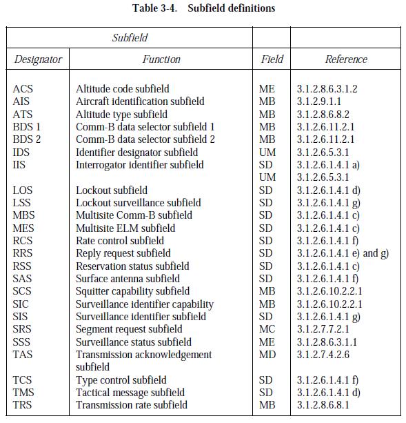
300 300
THE CIVIL AVIATION ACT (NO 21 OF 2013) REGULATIONS DRAFT CIVIL AVIATION (SURVEILLANCE AND COLLISION AVOIDANCE SYSTEMS) REGULATIONS, 2017.
 REGULATIONS DRAFT CIVIL AVIATION (SURVEILLANCE AND COLLISION AVOIDANCE SYSTEMS) REGULATIONS, 2017.") LEGAL NOTICE. THE CIVIL AVIATION ACT (NO 21 OF 2013) REGULATIONS DRAFT CIVIL AVIATION (SURVEILLANCE AND COLLISION AVOIDANCE SYSTEMS) REGULATIONS, 2017. ARRANGEMENT OF REGULATIONS Regulation PART I PRELIMINARY
LEGAL NOTICE. THE CIVIL AVIATION ACT (NO 21 OF 2013) REGULATIONS DRAFT CIVIL AVIATION (SURVEILLANCE AND COLLISION AVOIDANCE SYSTEMS) REGULATIONS, 2017. ARRANGEMENT OF REGULATIONS Regulation PART I PRELIMINARY
GOVERNMENT OF INDIA OFFICE OF DIRECTOR GENERAL OF CIVIL AVIATION TECHNICAL CENTRE, OPP SAFDARJANG AIRPORT, NEW DELHI
 GOVERNMENT OF INDIA OFFICE OF DIRECTOR GENERAL OF CIVIL AVIATION TECHNICAL CENTRE, OPP SAFDARJANG AIRPORT, NEW DELHI CIVIL AVIATION REQUIREMENTS SECTION 9 AIR SPACE AND AIR TRAFFIC MANAGEMENT SERIES 'D',
INTERNATIONAL STANDARDS AND RECOMMENDED PRACTICES
 Annex or Recommended Practice Chapter 1 Definition INTERNATIONAL STANDARDS AND RECOMMENDED PRACTICES CHAPTER 1. DEFINITIONS N1.All references to Radio Regulations are to the Radio Regulations published
Aeronautical Telecommunications
 International Standards and Recommended Practices Annex 10 to the Convention on International Civil Aviation Aeronautical Telecommunications Volume IV Surveillance and Collision Avoidance Systems This
TRANSMITTAL NOTE NEW EDITIONS OF ANNEXES TO THE CONVENTION ON INTERNATIONAL CIVIL AVIATION
 TRANSMITTAL NOTE NEW EDITIONS OF ANNEXES TO THE CONVENTION ON INTERNATIONAL CIVIL AVIATION It has come to our attention that when a new edition of an Annex is published, users have been discarding, along
Copyrighted Material - Taylor & Francis
 22 Traffic Alert and Collision Avoidance System II (TCAS II) Steve Henely Rockwell Collins 22. Introduction...22-22.2 Components...22-2 22.3 Surveillance...22-3 22. Protected Airspace...22-3 22. Collision
10 Secondary Surveillance Radar
 10 Secondary Surveillance Radar As we have just noted, the primary radar element of the ATC Surveillance Radar System provides detection of suitable targets with good accuracy in bearing and range measurement
Organización de Aviación Civil Internacional. Международная организация гражданской авиации. Ref.: AN 7/ /78 27 November 2015
 International Civil Aviation Organization Organisation de l aviation civile internationale Organización de Aviación Civil Internacional Международная организация гражданской авиации Tel.: +1 514-954-8219
Technical Standard Order
 Department of Transportation Federal Aviation Administration Aircraft Certification Service Washington, DC TSO-C74c Date: 2/20/73 Technical Standard Order Subject: TSO-C74c, AIRBORNE ATC TRANSPONDER EQUIPMENT
11 Traffic-alert and Collision Avoidance System (TCAS)
") 11 Traffic-alert and Collision Avoidance System (TCAS) INSTRUMENTATION 11.1 Introduction In the early nineties the American FAA stated that civil aircraft flying in US airspace were equipped with a Traffic-alert
11 Traffic-alert and Collision Avoidance System (TCAS) INSTRUMENTATION 11.1 Introduction In the early nineties the American FAA stated that civil aircraft flying in US airspace were equipped with a Traffic-alert
ICAO SARPS AND GUIDANCE DOCUMENTS ON SURVEILLANCE SYSTEMS
 ICAO SARPS AND GUIDANCE DOCUMENTS ON SURVEILLANCE SYSTEMS MEETING/WORKSHOP ON AUTOMATIC DEPENDENT SURVEILLANCE BROADCAST (ADS B) IMPLEMENTATION (ADS B/IMP) (Lima, Peru, 13 to 16 November 2017) ONOFRIO
Guidance Material for ILS requirements in RSA
 Guidance Material for ILS requirements in RSA General:- Controlled airspace required with appropriate procedures. Control Tower to have clear and unobstructed view of the complete runway complex. ATC to
Ref.: AN 7/ /29 27 March 2018
 International Civil Aviation Organization Organisation de l aviation civile internationale Organización de Aviación Civil Internacional Международная организация гражданской авиации Tel.: +1 514-954-8219
Impact of ATC transponder transmission to onboard GPS-L5 signal environment
 SCRSP-WG IP-A10 18 May 2006 SURVEILLANCE AND CONFLICT RESOLUTION SYSTEMS PANEL (SCRSP) TENTH MEETING WG-A Montreal, May, 2006 WG-A Agenda Item 9 Any Other Bussiness Impact of ATC transponder transmission
Technical Standard Order
 Department of Transportation Federal Aviation Administration Aircraft Certification Service Washington, DC TSO-C147 Date: 4/6/98 Technical Standard Order Subject: TSO-C147, TRAFFIC ADVISORY SYSTEM (TAS)
An advisory circular may also include technical information that is relevant to the standards or requirements.
 Advisory Circular AC91-24 Automatic Dependent Surveillance Broadcast (ADS-B) Systems Revision 0 24 July 2018 General Civil Aviation Authority advisory circulars contain guidance and information about standards,
Operating on the Radio Frequency of 1090 Megahertz (MHz)
") Deviation Request #107 for an ETSO approval for CS ETSO applicable to Extended Squitter Automatic Dependent Surveillance Broadcast (ADS B) and Traffic Information Service Broadcast (TIS B) Equipment Operating
Deviation Request #107 for an ETSO approval for CS ETSO applicable to Extended Squitter Automatic Dependent Surveillance Broadcast (ADS B) and Traffic Information Service Broadcast (TIS B) Equipment Operating
TCAS Functioning and Enhancements
 TCAS Functioning and Enhancements Sathyan Murugan SASTRA University Tirumalaisamudram, Thanjavur - 613 402. Tamil Nadu, India. Aniruth A.Oblah KLN College of Engineering Pottapalayam 630611, Sivagangai
Ron Turner Technical Lead for Surface Systems. Syracuse, NY. Sensis Air Traffic Systems - 1
 Multilateration Technology Overview Ron Turner Technical Lead for Surface Systems Sensis Corporation Syracuse, NY Sensis Air Traffic Systems - 1 Presentation Agenda Multilateration Overview Transponder
2. ETSO 2C40c#3 VHF Omni-directional Ranging (VOR) Equipment
 Equipment") Deviation request #96 for an ETSO approval for CS-ETSO applicable to Airborne VHF Omni-directional Ranging (VOR) Equipment (ETSO-2C40c) Consultation Paper 1. Introductory note The hereby presented deviation
Deviation request #96 for an ETSO approval for CS-ETSO applicable to Airborne VHF Omni-directional Ranging (VOR) Equipment (ETSO-2C40c) Consultation Paper 1. Introductory note The hereby presented deviation
FCI Technology Investigations: L band Compatibility Criteria and Interference Scenarios Study
 FCI Technology Investigations: L band Compatibility Criteria and Interference Scenarios Study Deliverable C3: Compatibility criteria and test specification for SSR systems Edition Number 1.0 Edition Date
Mode S Skills 101. OK, so you ve got four basic surveillance skills, you ve got the: ATCRBS Skills Mode S Skills TCAS Skills ADS-B skills
 Mode S Skills 101 OK, so you ve got four basic surveillance skills, you ve got the: ATCRBS Skills Mode S Skills TCAS Skills ADS-B skills Fisher Fisher Slide 1 853D ELECTRONIC SYSTEMS GROUP MODE S 101 Prepared
AMENDMENT 85 TO THE INTERNATIONAL STANDARDS AND RECOMMENDED PRACTICES AERONAUTICAL TELECOMMUNICATIONS RESOLUTION OF ADOPTION
 AMENDMENT No. 85 TO THE INTERNATIONAL STANDARDS AND RECOMMENDED PRACTICES AERONAUTICAL TELECOMMUNICATIONS ANNEX 10 TO THE CONVENTION ON INTERNATIONAL CIVIL AVIATION VOLUME I (RADIO NAVIGATION AIDS) The
TEPZZ A_T EP A1 (19) (11) EP A1 (12) EUROPEAN PATENT APPLICATION. (51) Int Cl.: G01S 7/40 ( ) G01S 13/78 (2006.
 (11) EP A1 (12) EUROPEAN PATENT APPLICATION. (51) Int Cl.: G01S 7/40 ( ) G01S 13/78 (2006.") (19) TEPZZ 8789A_T (11) EP 2 87 89 A1 (12) EUROPEAN PATENT APPLICATION (43) Date of publication: 08.04.201 Bulletin 201/1 (1) Int Cl.: G01S 7/40 (2006.01) G01S 13/78 (2006.01) (21) Application number:
(19) TEPZZ 8789A_T (11) EP 2 87 89 A1 (12) EUROPEAN PATENT APPLICATION (43) Date of publication: 08.04.201 Bulletin 201/1 (1) Int Cl.: G01S 7/40 (2006.01) G01S 13/78 (2006.01) (21) Application number:
EVOLUTION OF AERONAUTICAL SURVEILLANCE
 EVOLUTION OF AERONAUTICAL SURVEILLANCE By: M. Paydar ICAO December 2010 Aeronautical Surveillance Airborne Surveillance Identification Position (at what time?) Additional info (e.g. velocity) Ground Surveillance
Reducing Test Flights Using Simulated Targets and a Carefully Chosen Set-up
 Reducing Test Flights Using Simulated Targets and a Carefully Chosen Set-up Edition: 001 Date: 18-FEB-09 Status: Released DOCUMENT DESCRIPTION Document Title Reducing Test Flights: Using Simulated Targets
Subject: Aeronautical Telecommunications Aeronautical Radio Frequency Spectrum Utilization
 GOVERNMENT OF INDIA OFFICE OF DIRECTOR GENERAL OF CIVIL AVIATION TECHNICAL CENTRE, OPP SAFDARJANG AIRPORT, NEW DELHI CIVIL AVIATION REQUIREMENTS SECTION 4 - AERODROME STANDARDS & AIR TRAFFIC SERVICES SERIES
EUROCONTROL Specification
 Edition date: March 2012 Reference nr: EUROCONTROL-SPEC-0147 ISBN: 978-2-87497-022-1 EUROCONTROL Specification EUROCONTROL Specification for ATM Surveillance System Performance (Volume 2 Appendices) EUROCONTROL
A Review of Vulnerabilities of ADS-B
 A Review of Vulnerabilities of ADS-B S. Sudha Rani 1, R. Hemalatha 2 Post Graduate Student, Dept. of ECE, Osmania University, 1 Asst. Professor, Dept. of ECE, Osmania University 2 Email: ssrani.me.ou@gmail.com
Exam questions: AE3-295-II
 Exam questions: AE3-295-II 1. NAVIGATION SYSTEMS (30 points) In this question we consider the DME radio beacon. [a] What does the acronym DME stand for? (3 points) DME stand for Distance Measuring Equipment
EUROCONTROL Specification for ATM Surveillance System Performance (Volume 2 Appendices)
") EUROCONTROL EUROCONTROL Specification for ATM Surveillance System Performance (Volume 2 Appendices) Edition: 1.1 Edition date: September 2015 Reference nr: EUROCONTROL-SPEC-147 ISBN: 978-2-87497-022-1
EUROCONTROL EUROCONTROL Specification for ATM Surveillance System Performance (Volume 2 Appendices) Edition: 1.1 Edition date: September 2015 Reference nr: EUROCONTROL-SPEC-147 ISBN: 978-2-87497-022-1
Rulemaking Hearing Rules of the Tennessee Department of Health Bureau of Health Licensure and Regulation Division of Emergency Medical Services
 Rulemaking Hearing Rules of the Tennessee Department of Health Bureau of Health Licensure and Regulation Division of Emergency Medical Services Chapter 1200-12-01 General Rules Amendments of Rules Subparagraph
Introduction. Traffic Symbology. System Description SECTION 12 ADDITIONAL FEATURES
 12.2 Traffic Advisory Systems (TAS) Introduction All information in this section pertains to the display and control of the Garmin GNS 430/GTS 800 interface. NOTE: This section assumes the user has experience
2. Radar receives and processes this request, and forwards it to Ground Datalink Processor (in our case named GRATIS)
") 1 Short Description The Traffic Information Service (TIS) provides information to the cockpit via data link that is similar to VFR radar traffic advisories normally received over voice radio. TIS is intended
1 Short Description The Traffic Information Service (TIS) provides information to the cockpit via data link that is similar to VFR radar traffic advisories normally received over voice radio. TIS is intended
RECOMMENDATION ITU-R SA.1624 *
 Rec. ITU-R SA.1624 1 RECOMMENDATION ITU-R SA.1624 * Sharing between the Earth exploration-satellite (passive) and airborne altimeters in the aeronautical radionavigation service in the band 4 200-4 400
MYANMAR CIVIL AVIATION REQUIREMENTS
 Civil Aviation Requirements THE REPULBIC OF THE UNION OF MYANMAR MINISTRY OF TRANSPORT DEPARTMENT OF CIVIL AVIATION MYANMAR CIVIL AVIATION REQUIREMENTS MCAR Part-5 ANS Section 9 Volume-V Aeronautical Telecommunications
Contextual note SESAR Solution description form for deployment planning
 Purpose: Release 5 SESAR Solution ID #114 Contextual note SESAR Solution description form for deployment planning This contextual note introduces a SESAR Solution (for which maturity has been assessed
AE4-393: Avionics Exam Solutions
 AE4-393: Avionics Exam Solutions 2008-01-30 1. AVIONICS GENERAL a) WAAS: Wide Area Augmentation System: an air navigation aid developed by the Federal Aviation Administration to augment the Global Positioning
SECTION 2 BROADBAND RF CHARACTERISTICS. 2.1 Frequency bands
 SECTION 2 BROADBAND RF CHARACTERISTICS 2.1 Frequency bands 2.1.1 Use of AMS(R)S bands Note.- Categories of messages, and their relative priorities within the aeronautical mobile (R) service, are given
DRAFT Validation Cross Reference Index. for the. UAT SARPS and Technical Manual V0.2
 DRAFT Cross Reference Index for the UAT SARPS and V0.2 Change Record Date/Version 31 March 2003, V0.1 27 May 2003, V0.2 Change Original draft presented at UAT Subgroup meeting in Montreal 31 March 4 April
RECOMMENDATION ITU-R S.1594 *
 Rec. ITU-R S.1594 1 RECOMMENDATION ITU-R S.1594 * Maximum emission levels and associated requirements of high density fixed-satellite service earth stations transmitting towards geostationary fixed-satellite
Performance objectives and functional requirements for the use of improved hybrid surveillance in European environment
 Performance objectives and functional requirements for the use of improved hybrid surveillance in European environment Document information Project TCAS Evolution Project Number 09.47.00 Project Manager
RF 1090 MHZ BAND LOAD MODEL
 RF 1090 MHZ BAND LOAD MODEL Tomáš Lipták 1, Stanislav Pleninger 2 Summary: Nowadays, the load of 1090 MHz frequency represents a key factor determining the quality of surveillance application in terms
HD Radio FM Transmission. System Specifications
 HD Radio FM Transmission System Specifications Rev. G December 14, 2016 SY_SSS_1026s TRADEMARKS HD Radio and the HD, HD Radio, and Arc logos are proprietary trademarks of ibiquity Digital Corporation.
Report ITU-R M (11/2017)
") Report ITU-R M.2413-0 (11/2017) Reception of automatic dependent surveillance broadcast via satellite and compatibility studies with incumbent systems in the frequency band 1 087.7-1 092.3 MHz M Series
Report ITU-R M.2413-0 (11/2017) Reception of automatic dependent surveillance broadcast via satellite and compatibility studies with incumbent systems in the frequency band 1 087.7-1 092.3 MHz M Series
Regulations. Aeronautical Radio Service
 Regulations Aeronautical Radio Service Version 1.0 Issue Date: 30 December 2009 Copyright 2009 Telecommunications Regulatory Authority (TRA). All rights reserved. P O Box 26662, Abu Dhabi, United Arab
Potential co-operations between the TCAS and the ASAS
 Potential co-operations between the TCAS and the ASAS An Abeloos, Max Mulder, René van Paassen Delft University of Technology, Faculty of Aerospace Engineering, Kluyverweg 1, 2629 HS Delft, the Netherlands
Potential interference from spaceborne active sensors into radionavigation-satellite service receivers in the MHz band
 Rec. ITU-R RS.1347 1 RECOMMENDATION ITU-R RS.1347* Rec. ITU-R RS.1347 FEASIBILITY OF SHARING BETWEEN RADIONAVIGATION-SATELLITE SERVICE RECEIVERS AND THE EARTH EXPLORATION-SATELLITE (ACTIVE) AND SPACE RESEARCH
HD Radio FM Transmission System Specifications
 HD Radio FM Transmission System Specifications Rev. D February 18, 2005 Doc. No. SY_SSS_1026s TRADEMARKS The ibiquity Digital logo and ibiquity Digital are registered trademarks of ibiquity Digital Corporation.
RECOMMENDATION ITU-R M.1639 *
 Rec. ITU-R M.1639 1 RECOMMENDATION ITU-R M.1639 * Protection criterion for the aeronautical radionavigation service with respect to aggregate emissions from space stations in the radionavigation-satellite
Monitoring Pulse Based Navigation Signals in Flight
 Monitoring Pulse Based Navigation Signals in Flight Rolf Seide Senior Manager Competence Center Flight Inspection Systems Aerodata AG Herrmann-Blenk-Strasse 36 D-38108 Braunschweig Fax: +49 531 2359 222
Automatic Dependent Surveillance -ADS-B
 ASECNA Workshop on ADS-B (Dakar, Senegal, 22 to 23 July 2014) Automatic Dependent Surveillance -ADS-B Presented by FX SALAMBANGA Regional Officer, CNS WACAF OUTLINE I Definition II Principles III Architecture
RECOMMENDATION ITU-R S.1341*
 Rec. ITU-R S.1341 1 RECOMMENDATION ITU-R S.1341* SHARING BETWEEN FEEDER LINKS FOR THE MOBILE-SATELLITE SERVICE AND THE AERONAUTICAL RADIONAVIGATION SERVICE IN THE SPACE-TO-EARTH DIRECTION IN THE BAND 15.4-15.7
GUIDELINES FOR THE APPLICATION FOR PUBLIC RADIOCOMMUNICATIONS SERVICE (PRS) LICENCES
 LICENCES") GN-35/2012 GUIDELINES FOR THE APPLICATION FOR PUBLIC RADIOCOMMUNICATIONS SERVICE (PRS) LICENCES Office of the Communications Authority Hong Kong August 2012 CONTENTS SECTION 1 The regulatory framework
GN-35/2012 GUIDELINES FOR THE APPLICATION FOR PUBLIC RADIOCOMMUNICATIONS SERVICE (PRS) LICENCES Office of the Communications Authority Hong Kong August 2012 CONTENTS SECTION 1 The regulatory framework
ACAS Xu UAS Detect and Avoid Solution
 ACAS Xu UAS Detect and Avoid Solution Wes Olson 8 December, 2016 Sponsor: Neal Suchy, TCAS Program Manager, AJM-233 DISTRIBUTION STATEMENT A. Approved for public release: distribution unlimited. Legal
SATELLITE NETWORK NOTIFICATION AND COORDINATION REGULATIONS 2007 BR 94/2007
 BR 94/2007 TELECOMMUNICATIONS ACT 1986 1986 : 35 SATELLITE NETWORK NOTIFICATION AND COORDINATION ARRANGEMENT OF REGULATIONS 1 Citation 2 Interpretation 3 Purpose 4 Requirement for licence 5 Submission
ADS-B Introduction Greg Dunstone
 ADS-B Introduction Greg Dunstone Surveillance Program Lead, Airservices Australia SURVEILLANCE Basics Primary and Secondary radar Why do we need Surveillance? Why surveillance? Improved safety Reduced
Advisory Circular AC91-5. Operation of Portable Electronic Devices (PEDs) During Flight Under IFR. Date: 1 April Subject: Author: Chris Lamain
 During Flight Under IFR. Date: 1 April Subject: Author: Chris Lamain") Advisory Circular Subject: Operation of Portable Electronic Devices (PEDs) During Flight Under IFR Date: 1 April 1997 Author: Chris Lamain AC91-5 1. GENERAL. Civil Aviation Authority Advisory Circulars
Advisory Circular Subject: Operation of Portable Electronic Devices (PEDs) During Flight Under IFR Date: 1 April 1997 Author: Chris Lamain AC91-5 1. GENERAL. Civil Aviation Authority Advisory Circulars
SURVEILLANCE SYSTEMS. Operational Improvement and Cost Savings, from Airport Surface to Airspace
 SURVEILLANCE SYSTEMS Operational Improvement and Cost Savings, from Airport Surface to Airspace Sergio Martins Director, Air Traffic Management - Latin America 2 AGENDA Airport Surface Solutions A-SMGCS
2 GHz Licence-exempt Personal Communications Service Devices (LE-PCS)
") RSS-213 Issue 2 December 2005 Spectrum Management and Telecommunications Radio Standards Specification 2 GHz Licence-exempt Personal Communications Service Devices (LE-PCS) Aussi disponible en français
RSS-213 Issue 2 December 2005 Spectrum Management and Telecommunications Radio Standards Specification 2 GHz Licence-exempt Personal Communications Service Devices (LE-PCS) Aussi disponible en français
TECHNICAL CONDITIONS FOR RADIO EQUIPMENT OF INMARSAT SHIP EARTH STATIONS, etc
 TECHNICAL CONDITIONS FOR RADIO EQUIPMENT OF INMARSAT SHIP EARTH STATIONS, etc (Article 7 paragraph 21, Article 14 paragraph 3, Article 40.4 paragraph 1 item 5, Article 40.4 paragraph 2 item 4, Article
International Civil Aviation Organization
 Doc 9688 AN/952 Manual on Mode S Specific Services Approved by the Secretary General and published under his authority Second Edition 2004 International Civil Aviation Organization AMENDMENTS Amendments
Mode 4A Unsafe terrain clearance with landing gear not down and flaps not in landing position
 1.6.18 Ground Proximity Warning System Allied Signal Aerospace (Honeywell) manufactures the GPWS, part number 965-0648- 008. The GPWS provides the following alerts if thresholds are exceeded: Mode 1 Excessive
Integration of surveillance in the ACC automation system
 Integration of surveillance in the ACC automation system ICAO Seminar on the Implementation of Aeronautical Surveillance and Automation Systems in the SAM Region San Carlos de Bariloche 6-8 Decembre 2010
Report on the Validation of the Requirements in the SARPs for UAT
 International Civil Aviation Organization 999 University Street Montreal, Quebec, Canada H3C 5H7 Report on the Validation of the Requirements in the SARPs for UAT Revision 2.0 4 April 2005 Prepared by:
Seychelles Civil Aviation Authority SAFETY NOTICE. Coding and registration of Seychelles 406 Mhz Emergency Locator Transmitters (ELTs)
") Seychelles Civil Aviation Authority Safety Notice SAFETY NOTICE Number: Issued: 25 April 2018 Coding and registration of Seychelles 406 Mhz Emergency Locator Transmitters (ELTs) This Safety Notice contains
Seychelles Civil Aviation Authority Safety Notice SAFETY NOTICE Number: Issued: 25 April 2018 Coding and registration of Seychelles 406 Mhz Emergency Locator Transmitters (ELTs) This Safety Notice contains
Modular Test Approaches for SSR Signal Analysis in IFF Applications
 Modular Test Approaches for SSR Signal Analysis in IFF Applications Military radar applications call for highly specialized test equipment Radar signal analysis applications require highly specialized
Advances in Military Technology Vol. 5, No. 2, December Selection of Mode S Messages Using FPGA. P. Grecman * and M. Andrle
 AiMT Advances in Military Technology Vol. 5, No. 2, December 2010 Selection of Mode S Messages Using FPGA P. Grecman * and M. Andrle Department of Aerospace Electrical Systems, University of Defence, Brno,
Evaluation Results of Multilateration at Narita International Airport
 Evaluation Results of Multilateration at Narita International Airport Hiromi Miyazaki, Tadashi Koga, Eisuke Ueda, Izumi Yamada, Yasuyuki Kakubari and Shiro Nihei Electronic Navigation Research Institute
RECOMMENDATION ITU-R S.1340 *,**
 Rec. ITU-R S.1340 1 RECOMMENDATION ITU-R S.1340 *,** Sharing between feeder links the mobile-satellite service and the aeronautical radionavigation service in the Earth-to-space direction in the band 15.4-15.7
Surveillance Strategy
 Surveillance Strategy ENRI International Workshop on ATM/CNS March 2009 Mel Rees Head of CNS EUROCONTROL 1 Pillars of ATM Ground Based Surveillance Non-Cooperative Independent Surveillance: Determines
The Global Flight Tracking (GFT) for Civil Aviation WRC-15 Report
 for Civil Aviation WRC-15 Report") The Global Flight Tracking (GFT) for Civil Aviation WRC-15 Report Dr. KY-Leng Deputy Director General General Department of Posts and Telecommunication Ministry of Posts and Telecommunication Email: leng-ky@mptc.gov.kh
The Global Flight Tracking (GFT) for Civil Aviation WRC-15 Report Dr. KY-Leng Deputy Director General General Department of Posts and Telecommunication Ministry of Posts and Telecommunication Email: leng-ky@mptc.gov.kh
KMD 550/850. Traffic Avoidance Function (TCAS/TAS/TIS) Pilot s Guide Addendum. Multi-Function Display. For Software Version 01/13 or later
 Pilot s Guide Addendum. Multi-Function Display. For Software Version 01/13 or later") N B KMD 550/850 Multi-Function Display Traffic Avoidance Function (TCAS/TAS/TIS) Pilot s Guide Addendum For Software Version 01/13 or later Revision 3 Jun/2004 006-18238-0000 The information contained
N B KMD 550/850 Multi-Function Display Traffic Avoidance Function (TCAS/TAS/TIS) Pilot s Guide Addendum For Software Version 01/13 or later Revision 3 Jun/2004 006-18238-0000 The information contained
SURVEILLANCE MONITORING OF PARALLEL PRECISION APPROACHES IN A FREE FLIGHT ENVIRONMENT. Carl Evers Dan Hicok Rannoch Corporation
 SURVEILLANCE MONITORING OF PARALLEL PRECISION APPROACHES IN A FREE FLIGHT ENVIRONMENT Carl Evers (cevers@rannoch.com), Dan Hicok Rannoch Corporation Gene Wong Federal Aviation Administration (FAA) ABSTRACT
ARTICLE 22. Space services 1
 CHAPTER VI Provisions for services and stations RR22-1 ARTICLE 22 Space services 1 Section I Cessation of emissions 22.1 1 Space stations shall be fitted with devices to ensure immediate cessation of their
AIR ROUTE SURVEILLANCE 3D RADAR
 AIR TRAFFIC MANAGEMENT AIR ROUTE SURVEILLANCE 3D RADAR Supplying ATM systems around the world for more than 30 years indracompany.com ARSR-10D3 AIR ROUTE SURVEILLANCE 3D RADAR ARSR 3D & MSSR Antenna Medium
Digital Transmission Systems (DTSs), Frequency Hopping Systems (FHSs) and Licence-Exempt Local Area Network (LE-LAN) Devices
, Frequency Hopping Systems (FHSs) and Licence-Exempt Local Area Network (LE-LAN) Devices") Issue 1 2015 Spectrum Management and Telecommunications Radio Standards Specification Digital Transmission Systems (DTSs), Frequency Hopping Systems (FHSs) and Licence-Exempt Local Area Network (LE-LAN)
Issue 1 2015 Spectrum Management and Telecommunications Radio Standards Specification Digital Transmission Systems (DTSs), Frequency Hopping Systems (FHSs) and Licence-Exempt Local Area Network (LE-LAN)
Radiocommunications Regulations (General User Radio Licence for Aeronautical Purposes) Notice 2016
 Notice 2016") Radiocommunications Regulations (General User Radio Licence for Aeronautical Purposes) Notice 2016 Pursuant to section 111 of the Radiocommunications Act 1989 and Regulation 9 of the Radiocommunications
Radiocommunications Regulations (General User Radio Licence for Aeronautical Purposes) Notice 2016 Pursuant to section 111 of the Radiocommunications Act 1989 and Regulation 9 of the Radiocommunications
Fisheries and Marine Resources (Automatic Identification System) Regulations
 Regulations") Fisheries and Marine Resources (Automatic Identification System) Regulations 2016 GN No. 116 of 2016 Government Gazette of Mauritius No. 47of 28 May 2016 THE FISHERIES AND MARINE RESOURCES ACT Regulations
Fisheries and Marine Resources (Automatic Identification System) Regulations 2016 GN No. 116 of 2016 Government Gazette of Mauritius No. 47of 28 May 2016 THE FISHERIES AND MARINE RESOURCES ACT Regulations
Radio Transmitters and Receivers Operating in the Land Mobile and Fixed Services in the Frequency Range MHz
 Issue 11 June 2011 Spectrum Management and Telecommunications Radio Standards Specification Radio Transmitters and Receivers Operating in the Land Mobile and Fixed Services in the Frequency Range 27.41-960
COMPARISON OF SURVEILLANCE TECHNOLOGIES ICAO
 COMPARISON OF SURVEILLANCE TECHNOLOGIES By: M. Paydar ICAO ICAO Seminar on the Implementation of Aeronautical Surveillance and Automation Systems in the SAM Region (San Carlos de Bariloche, Argentina,
esa Space Station Electromagnetic Emission and Susceptibility Requirements International Space Station Revision C May 31, 1996 SSP Revision C
 Space Station Electromagnetic Emission and Susceptibility Requirements International Space Station Revision C May 31, 1996 esa european space agency National Aeronautics and Space Administration Space
AIR SURVEILLANCE FOR SMART LANDING FACILITIES IN THE SMALL AIRCRAFT TRANSPORATION SYSTEM. By Eric J. Shea
 AIR SURVEILLANCE FOR SMART LANDING FACILITIES IN THE SMALL AIRCRAFT TRANSPORATION SYSTEM By Eric J. Shea Thesis submitted to the Faculty of Virginia Polytechnic Institute and State University (Virginia
Use of Satellite-based Technologies to Enhance safety and efficiency in ATC and Airport Operation
 Use of Satellite-based Technologies to Enhance safety and efficiency in ATC and Airport Operation Presented by Felix Tsao Senior Electronics Engineer Civil Aviation Department 26 May 2017 1 Briefing on
ICAO AFI/MID ASBU IMPLEMENTATION WORKSHOP. Cairo, November 2015
 ICAO AFI/MID ASBU IMPLEMENTATION WORKSHOP Cairo, 23-26 November 2015 1 2 List of Contents Why ASBU? ASBU Module ( B0-SURF ). A-SMGCS Functions. A-SMGCS Implementation Levels. How does A-SMGCS work? A-SMGCS
European Mode S Station Functional Specification
 EUROPEAN ORGANISATION FOR THE SAFETY OF AIR NAVIGATION EUROCONTROL European Mode S Station Functional Edition : 3.11 Edition Date : 9 May 2005 Status : Released Issue Class : General Public EUROPEAN AIR
AMCP/8-WP/66. APPENDIX (English only) COMPARATIVE ANALYSIS OF ADS-B LINKS
 COMPARATIVE ANALYSIS OF ADS-B LINKS") Appendix to the Report on Agenda Item 4 4A-1 APPENDIX (English only) COMPARATIVE ANALYSIS OF ADS-B LINKS References 1. Air Navigation Commission Minutes of the Eleventh Meeting of the 160th Session. 2.
Appendix to the Report on Agenda Item 4 4A-1 APPENDIX (English only) COMPARATIVE ANALYSIS OF ADS-B LINKS References 1. Air Navigation Commission Minutes of the Eleventh Meeting of the 160th Session. 2.
Communication and Navigation Systems for Aviation
 Higher National Unit Specification General information for centres Unit title: Communication and Navigation Systems for Aviation Unit code: F0M3 35 Unit purpose: This Unit is designed to allow candidates
RECOMMENDATION ITU-R SNG * Uniform technical standards (analogue) for satellite news gathering (SNG)
 for satellite news gathering (SNG)") Rec. ITU-R SNG.722-1 1 RECOMMENDATION ITU-R SNG.722-1 * Uniform technical standards (analogue) for satellite news gathering (SNG) (1990-1992) The ITU Radiocommunication Assembly, considering a) that satellite
Rec. ITU-R SNG.722-1 1 RECOMMENDATION ITU-R SNG.722-1 * Uniform technical standards (analogue) for satellite news gathering (SNG) (1990-1992) The ITU Radiocommunication Assembly, considering a) that satellite
Federal Communications Commission Office of Engineering and Technology Laboratory Division
 April 9, 2013 Federal Communications Commission Office of Engineering and Technology Laboratory Division Guidance for Performing Compliance Measurements on Digital Transmission Systems (DTS) Operating
EE Chapter 14 Communication and Navigation Systems
 EE 2145230 Chapter 14 Communication and Navigation Systems Two way radio communication with air traffic controllers and tower operators is necessary. Aviation electronics or avionics: Avionic systems cover
This Licence replaces the licence issued by Ofcom on 25 April 2006 to Manx Telecom Limited.
 Office of Communications (Ofcom) Wireless Telegraphy Act 2006 PUBLIC WIRELESS NETWORK LICENCE This Licence replaces the licence issued by Ofcom on 25 April 2006 to Manx Telecom Limited. Licence no. 0261634
Conformity and Interoperability Training Homologation Procedures and Type Approval Testing for Mobile Terminals
 Conformity and Interoperability Training Homologation Procedures and Type Approval Testing for Mobile Terminals ITU C&I Programme Training Course on Testing Mobile Terminal Schedule RF Tests (Functional)
Band Class Specification for cdma2000 Spread Spectrum Systems
 GPP C.S00 Version.0 Date: February, 00 Band Class Specification for cdma000 Spread Spectrum Systems Revision 0 COPYRIGHT GPP and its Organizational Partners claim copyright in this document and individual
Tel.: +1 (514) , ext Ref.: AN 7/ /26 9 April 2009
 , ext Ref.: AN 7/ /26 9 April 2009") International Civil Aviation Organization Organisation de l aviation civile internationale Organización de Aviación Civil Internacional Международная организация гражданской авиации Tel.: +1 (514) 954-8219,
International Civil Aviation Organization Organisation de l aviation civile internationale Organización de Aviación Civil Internacional Международная организация гражданской авиации Tel.: +1 (514) 954-8219,
Clarification. Mode S Transponder. in an Airport/A-SMGCS Environment
 EUROPEAN ORGANISATION FOR THE SAFETY OF AIR NAVIGATION EUROCONTROL Clarification Mode S Transponder in an Airport/A-SMGCS Environment MODES/SYS/002 Edition : 1.1 Edition Date : 3 May 2005 Status : Released
UPDATES to the. Rules of Procedure. (Edition of 1998) approved by the Radio Regulations Board. Contents
 approved by the Radio Regulations Board. Contents") UPDATES to the Rules of Procedure (Edition of 1998) approved by the Radio Regulations Board Revision (1) (Circular No.) Date Part ARS Pages to be removed Pages to be inserted 1 June 1999 A1 ARS5 15-18
UPDATES to the Rules of Procedure (Edition of 1998) approved by the Radio Regulations Board Revision (1) (Circular No.) Date Part ARS Pages to be removed Pages to be inserted 1 June 1999 A1 ARS5 15-18
RECOMMENDATION ITU-R SA (Question ITU-R 210/7)
") Rec. ITU-R SA.1016 1 RECOMMENDATION ITU-R SA.1016 SHARING CONSIDERATIONS RELATING TO DEEP-SPACE RESEARCH (Question ITU-R 210/7) Rec. ITU-R SA.1016 (1994) The ITU Radiocommunication Assembly, considering
Rec. ITU-R SA.1016 1 RECOMMENDATION ITU-R SA.1016 SHARING CONSIDERATIONS RELATING TO DEEP-SPACE RESEARCH (Question ITU-R 210/7) Rec. ITU-R SA.1016 (1994) The ITU Radiocommunication Assembly, considering
ADS-B and WFP Operators. Safety Advantages Security Concerns. Thomas Anthony Director U.S.C. Aviation Safety and Security Program ADS-B
 ADS-B and WFP Operators Safety Advantages Security Concerns Thomas Anthony Director U.S.C. Aviation Safety and Security Program ADS-B How can ADS-B be useful for Humanitarian Air Operation? Are there security
AT01 AIRPLANE FLIGHT MANUAL
 Table of Contents Supplement AVE12 1. Section 1 General AVE12 3 2. Section 2 Operating Limitations AVE12 3 3. Section 3 Emergency Procedures AVE12 3 4. Section 4 Normal Procedures AVE12 4 5. Section 5