Closed-Loop Pneumatics Workbook TP 111
|
|
|
- Laurel Fowler
- 6 years ago
- Views:
Transcription

1 Closed-Loop Pneumatics Workbook TP 111 Festo Didactic en
2 Authorised applications and liability The Learning System for Automation has been developed and prepared exclusively for training in the field of automation. The training organization and / or trainee shall ensure that the safety precautions described in the accompanying Technical documentation are fully observed. Festo Didactic hereby excludes any liability for injury to trainees, to the training organization and / or to third parties occurring as a result of the use or application of the station outside of a pure training situation, unless caused by premeditation or gross negligence on the part of Festo Didactic. Order No.: Description: TEACHW. PNEUM Designation: D.S111-C-SIBU-GB Edition: Layout: , OCKER Ingenieurbüro Graphics: OCKER Ingenieurbüro Authors: J. Gerhartz, D. Scholz Copyright by Festo Didactic GmbH & Co., D Denkendorf 2001 The copying, distribution and utilization of this document as well as the communication of its contents to others without expressed authorization is prohibited. Offenders will be held liable for the payment of damages. All rights reserved, in particular the right to carry out patent, utility model or ornamental design registrations. Parts of this training documentation may be duplicated, solely for training purposes, by persons authorised in this sense. TP111 Festo Didactic
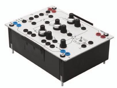
3 3 Preface The Learning System for Automation by Festo Didactic is formulated according to various training prerequisites and vocational requirements. It has been divided into the following training packages: Basic packages which convey basic knowledge spanning a wide range of technologies Technology packages which deal with important subjects of open and closed-loop control technology Function packages to explain the basic functions of automated systems Application packages to facilitate practice-orientated vocational and further training. The technology packages deal with the technologies of pneumatics, electro-pneumatics, programmable logic controllers, hydraulics, electrohydraulics, proportional hydraulics, closed-loop pneumatics and hydraulics. Mounting frame Fig. 1: Pneumatics 2000 i.e. mobile workstation Profile plate U = 230 V~ p = 6 MPa Storage tray
4 4 The modular design of the Learning System permits applications beyond the scope of the individual packages. It is, for instance, possible to design PLC-controlled systems with pneumatic, hydraulic and electrical actuators. All training packages are based on an identical structure: Hardware Teachware Software Seminars The hardware consists of industrial components and systems which have been adapted for didactic purposes. The courseware has been designed in line with didactic methods and coordinated for use with the training hardware. The courseware comprises: Textbooks (with exercises and examples) Workbooks (with practical exercises, explanatory notes, solutions and data sheets) Transparencies and videos (to create a lively training environment) The training and learning media is available in several languages, which has been designed for use in the classroom as well as for self-tuition. The software sector serves as a basis for providing computer training programs and programming software for programmable logic controllers. A comprehensive range of seminars on the subject of the various technology packages completes our program of vocational and further training.
5 5 Contents Technology package TP 111 Closed-Loop Pneumatics 11 Component/exercise table 12 Workbook concept 13 Equipment set TP Safety instructions 16 Symbols for equipment set 17 Section A Course I. Non-dynamic closed-loop pressure control circuit Exercise 1: Exercise 2: Exercise 3: Exercise 4: Exercise 5: Maintenance of a pressure gauge Characteristic of an analogue pressure sensor A-3 Spot-welding machine Mode of operation of a comparator A-13 Packaging machine Transition functions of controlled systems A-23 Reservoir-charging circuit, commissioning of a two-step-action controller with a switching pressure difference A-33 Tyre test-rig Commissioning of a three-step-action controller A-45 II. Dynamic closed-loop pressure control circuit Exercise 6: Exercise 7: Exercise 8: Exercise 9: Pneumatic press Mode of operation of a proportional valve A-53 Quality assurance Mode of operation of a PID controller A-63 Baffle-plate flow sensor Transition function of a P controller A-73 Pneumatic post system Direction of action and commissioning of a P control circuit A-87
6 6 Exercise 10: Exercise 11: Exercise 12: Exercise 13: Exercise 14: Exercise 15: Exercise 16: Clamping device Control quality and limit of stability of a P control circuit A-95 Pneumatic screwdriver Transition function of an I and PI controller A-105 Injection-moulding machine Empirical setting of parameters of a PI controller A-123 Forming of moulded packaging Transition functions of D, PD and PID controllers A-131 Bending device Empirical setting of parameters of a PID controller A-147 Papermaking machine Influence of interference variables A-155 Testing machine Setting of parameters using the Ziegler-Nichols method A-165 III. Closed-loop position control circuit Exercise 17: Exercise 18: Exercise 19: Exercise 20: Exercise 21: Stamping machine Transition function of a controlled system without compensation Mode of operation of a linear potentiometer A-177 Sorting device Structure of a status controller A-187 Deburring an engine block Setting the parameters of a status controller A-197 Cake production Lag error and closed-loop gain A-209 Pallettizing station Influence of mass load and tubing volume A-221
7 7 Section B Fundamentals Chapter 1 Fundamentals B Signal B Block diagram B Signal flow diagram B Test signals B Open-loop and closed-loop control B Closed control loop terminology B Stability and instability B Steady-state and dynamic behaviour B Response to setpoint changes and interference B Fixed-value, follow-up and timing control systems B Differentiation of a signal B Integration of a signal B-39 Chapter 2 Pneumatic Closed-Loop Controlled Systems B Controlled systems with and without compensation B Short-delay pneumatic closed-loop controlled systems B First-order pneumatic closed-loop controlled systems B Second-order pneumatic closed-loop controlled systems B Third-order pneumatic closed-loop controlled systems B Controlled systems with dead time B Classification of controlled systems according to their step response behaviour B Operating point and system gain B-54
8 8 Chapter 3 Controller Structures B Two-step action controller B Three-step action controller B Multi-step action controller B Block diagrams for non-dynamic controllers B P controller B I controller B D controller B PI, PD, PID controllers B Block diagrams for standard dynamic controllers B Status controller B Selection of controller structure B Response to interference and control factor B-91 Chapter 4 Technical Implementation of Controllers B Structure of closed-loop control circuits B Pneumatic and electrical controllers B Analogue and digital controllers B Selection of a controller B-110 Chapter 5 Directional Control Valves B Purpose of a directional control valve B Valve designs B Mode of operation of a dynamic 5/3-way valve B Designations and symbols for dynamic directional control valves B Steady-state characteristics for dynamic directional control valves B Dynamic behaviour of dynamic directional control valves B Selection criteria for directional control valves B-137
9 9 Chapter 6 Pressure Regulators B Purpose of a pressure regulator B Designs of pressure regulators B Mechanical pressure regulator B Electrically-actuated pressure regulators, with mechanical adjustment B Electrically-actuated pressure regulators, with electrical adjustment B Pressure regulation with a directional control B Selection criteria for pressure regulators B-151 Chapter 7 Measuring Systems B Purpose of a measuring system B Measuring-system designs and interfaces B Selection criteria for measuring systems B-158 Chapter 8 Assembly, Commissioning and Fault-Finding B Closed-loop control circuits in automation B Planning B Assembly B Commissioning B Controller settings B Fault-finding B-176
10 10 Part C Solutions Solution 1: Maintenance of a pressure gauge C-3 Solution 2: Spot-welding machine C-5 Solution 3: Packaging machine C-9 Solution 4: Reservoir-charging circuit C-11 Solution 5: Tyre test-rig C-13 Solution 6: Pneumatic press C-15 Solution 7: Quality assurance C-17 Solution 8: Baffle-plate flow sensor C-19 Solution 9: Pneumatic post system C-21 Solution 10: Clamping device C-23 Solution 11: Pneumatic screwdriver C-25 Solution 12: Injection-moulding machine C-29 Solution 13: Forming of moulded packaging C-31 Solution 14: Bending device C-35 Solution 15: Papermaking machine C-39 Solution 16: Testing machine C-43 Solution 17: Stamping machine C-47 Solution 18: Sorting device C-49 Solution 19: Deburring an engine block C-51 Solution 20: Cake production C-55 Solution 21: Pallettizing station C-59 Section D - Appendix List of applicable guidelines and standards D-2 List of literature D-4 Index D-5 Data sheets D-13
11 11 Technology package TP 111 Closed-Loop Pneumatics The technology package TP111 Closed-Loop Pneumatics forms part of Festo Didactic s Learning System for Automation and Communications. The training aims of TP111 are concerned with analogue closed-loop control technology. Actuators are activated via electrical open and closed-loop components. Students working through technology package TP110 should preferably have basic knowledge of electropneumatics and measuring systems. The equipment set is designed in such a way that the number of components required becomes larger from one exercise to the next. This makes it possible to begin a study of closed-loop control technology with a small number of components, which can then be added to as necessary. The exercises of TP111 are concerned with three main subjects: Non-dynamic pressure regulation (exercises 1 5) Dynamic pressure regulation (exercises 6 16) Position control (exercises 17 21) The components required for particular exercises can be seen in the component/exercise table over leaf.
12 12 Component/exercise table Exercises Description Service unit with on/off valve Manifold PUN tubing 10 m Signal input plate Analogue pressure sensor Comparator Reservoir One-way flow control valve Pressure gauge /2-way solenoid valve with push button 1 2 Push-in T connector /2-way solenoid valve /3-way solenoid valve 1 Connector components /3-way proportional valve PID controller Linear actuator 450 mm Mounting kit for potentiometer Loading weight 50 N 1 Linear potentiometer Status controller Scale 450 mm 1 Cable set Digital multimeter Power supply unit Setpoint card (1) (1) (1) (1) (1) (1) (1) (1) (1) (1) (1) (1) (1) (1) (1) (1) Function generator (1) (1) (1) (1) (1) (1) (1) (1) (1) (1) (1) (1) (1) (1) (1) (1) Storage oscilloscope Cable BNC-4 mm Connection panel 1
13 13 Workbook concept The workbook is divided into the following sections: Section A Course Section B Fundamentals Section C Solutions Section D Appendix In Section A, Course, progressive exercises are used to explain the assembly and commissioning of analogue closed-loop control circuits. The necessary technical knowledge required to complete an exercise is provided at the start of the exercise concerned. Non-essential detail is avoided. More detailed information is given is Section B. Section C, Solutions, gives the results of the exercises in Section A, with explanatory notes. Section B, Fundamentals, contains general technical knowledge which complements the training aims of the exercises in Section A. Theoretical relationships are demonstrated and the necessary specialist terminology is explained in an easily understandable way with examples. Section D, Appendix, is intended for use as a reference work. It contains data sheets, a list of literature and an index. The structure of the book has been designed to allow the use of its contents both for practical training, e.g. in classroom courses, and for self-study purposes
14 14 Equipment set TP111 Order No.: General Equipment set TP /200, Order No.: Description Order No. Quantity Signal input plate, electrical Push-in T connector Plastic tubing, 10 m, silver-metallic, 4 x Plastic tubing, 5 m, silver-metallic, 6 x /2-way valve with pushbutton Pressure gauge One-way flow control valve Service unit with on/off valve Manifold Connector components /2-way solenoid valve, normally closed Pressure regulation Equipment set TP111 Pressure, Order No.: Description Order No. Quantity Komparatorkarte PID-Reglerkarte /3-Wege-Magnetventil, in Ruhestellung gesperrt Druckluftspeicher Analog-Drucksensor /3-Wege-Proportionalventil
15 15 Equipment set TP111 Position, Order No.: Positioning Description Order No. Quantity Scale 450 mm Loading weight Connection panel (loading weight) Linear actuator 450 mm Status controller card Linear potentiometer Mounting kit for potentiometer Cable for linear potentiometer Shock absorber Description Order No. Quantity Courseware Workbook german Workbook english Description Order No. Quantity Accessories Cable set Digital multimeter Setpoint card Power supply unit Oscilloscope Function generator Cable BNC 4 mm Plug-in adapter
16 16 Safety instructions In the interests of your own safety, please follow the instructions given below: Mount all components securely on the plate. When commissioning control circuits, always switch on first the electrical power supply and then the compressed air. When switching off, work in reverse order. Do not switch on the compressed air until you have connected up and secured all the tubing. Exercise great care when switching on the compressed air. Cylinders may advance or retract unexpectedly. Shut off the compressed air supply immediately if tubing becomes detached. This will help to prevent accidents. Never disconnect tubing while this is under pressure. Never exceed the maximum permissible operating pressure of 8 bar. You will need a maximum of 6 bar to carry out the exercises in the course. Please also observe the general safety instructions of DIN58126 and VDE 100. Use only extra-low voltage supplies, maximum 24 V DC. Before commissioning closed-loop control circuits, check not only the pneumatic lines but also the electrical cables and connections. Please note that the slide of the linear drive is fitted with powerful magnets. Do not bring any diskettes or other objects sensitive to magnetic fields into the vicinity of these magnets. Observe the data sheets referring to individual components, particularly with regard to safety instructions.
17 17 Symbols for equipment set Compressor with constant displacement volume Pressure source Symbols for equipment set Reservoir Pressure regulating valve One-way flow control valve Filter: Separating and filtering of dirt particles Water separator, manual actuation Water separator, automatic Lubricator: Metered quantities dispersed into air flow Service unit consisting of compressed air filter, pressure regulator, pressure gauge and lubricator Service unit, simplified representation with lubricator Service unit, simplified representation without lubricator
18 18 Symbols for equipment set Double-acting cylinder with single-ended piston rod Double-acting cylinder with double-ended piston rod Double-acting cylinder without piston rod Earth/ground Pressure gauge Shut-off valve Manual operation Outlet port one threaded connection Plugged port 3/2-way valve normally closed 3/3-way valve mid position closed 3/3-way dynamic valve single working line 5/2-way valve two working lines 5/2-way dynamic valve two working lines 5/3-way valve mid position closed 5/3-way dynamic valve two working lines
19 19 Linear scale Regulator general Symbols of equipment set Converter general Adjuster general Pressure gauge general Limiter electrical Pressure sensor electrical Pressure sensor pneumatic Amplifier general Operation amplifier general Electrical actuation Solenoid with one winding Electrical actuation solenoid with two opposed windings infinitely adjustable Manual actuation by means of spring Pilot actuated indirect by application of pressure
20 20 Symbole des Gerätesatzes Switch detent function Working line line for energy transmission Line connection fixed connection Link collecting or summation point Electrical line line for electrical power transmission Oscilloscope Display indicator light Voltmeter Transmission element proportional time response Transmission element PT1 time response Transmission element with integral time response Transmission element with differential time response
21 21 Transmission element two step action without hysteresis Transmission element hysteresis, differential Symbols for equipment set Comparator Transmission element three step action Transmission element three step action with two different hystereses Transmission element with PD time response Transmission element with PI time response Transmission element with PID time response Voltage generator D.C.voltage Voltage generator square-wave voltage Voltage generator sine-wave voltage Voltage generator triangular-wave voltage
22 22
23 A-1 Section A Course I. Non-dynamic closed-loop pressure control circuit Exercise 1: Exercise 2: Exercise 3: Exercise 4: Exercise 5: Maintenance of a pressure gauge Characteristic of an analogue pressure sensor A-3 Spot-welding machine Mode of operation of a comparator A-13 Packaging machine Transition functions of controlled systems A-23 Reservoir-charging circuit, commissioning of a two-step-action controller with a switching pressure difference A-33 Tyre test-rig Commissioning of a three-step-action controller A-45 II. Dynamic closed-loop pressure control circuit Exercise 6: Exercise 7: Exercise 8: Exercise 9: Exercise 10: Pneumatic press Mode of operation of a proportional valve A-53 Quality assurance Mode of operation of a PID controller A-63 Baffle-plate flow sensor Transition function of a P controller A-73 Pneumatic post system Direction of action and commissioning of a P control circuit A-87 Clamping device Control quality and limit of stability of a P control circuit A-95 TP111 Festo Didactic
24 A-2 Exercise 11: Exercise 12: Exercise 13: Exercise 14: Exercise 15: Exercise 16: Pneumatic screwdriver Transition function of an I and PI controller A-105 Injection-moulding machine Empirical setting of parameters of a PI controller A-123 Forming of moulded packaging Transition functions of D, PD and PID controllers A-131 Bending device Empirical setting of parameters of a PID controller A-147 Papermaking machine Influence of interference variables A-155 Testing machine Setting of parameters using the Ziegler-Nichols method A-165 III. Closed-loop position control circuit Exercise 17: Exercise 18: Exercise 19: Exercise 20: Exercise 21: Stamping machine Transition function of a controlled system without compensation Mode of operation of a linear potentiometer A-177 Sorting device Structure of a status controller A-187 Deburring an engine block Setting the parameters of a status controller A-197 Cake production Lag error and closed-loop gain A-209 Pallettizing station Influence of mass load and tubing volume A-221 TP111 Festo Didactic
25 A-3 Exercise 1 Closed-loop pneumatics Maintenance of a pressure gauge To be able to distinguish between sensors according to their signal types To be able to explain the design and mode of operation of an analogue pressure sensor To be able to produce and evaluate characteristics for sensors Subject Title Training aims Sensor Technical knowledge A sensor acquires a measured variable, such as temperature, filling level or torque, and converts this into an electrical or mechanical signal. Sensors are classified as binary, digital or analogue types, depending on the signal they produce. Binary sensor A binary sensor produces an output signal which can have one of two switching statuses (e.g. on/off or 0 V / 10 V). Digital sensor A digital sensor produces an output signal which corresponds to a number, created for example by the addition of several pulses. Analogue sensor An analogue sensor produces an output signal which can be represented by a continuous curve (e.g. the deflection of the pointer of a pressure gauge) Sensors are also occasionally referred to as signal pick-ups, signal converters or as measuring systems or measuring transducers. TP111 Festo Didactic
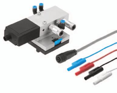
26 A-4 Exercise 1 Analogue pressure sensors The pressure sensor used in this case converts the measured variable pressure into an electrical signal. The permissible input pressure is between 0 and 10 bar positive pressure. The sensor supplies two output variables: A voltage of between 0 and 10 V, A current of between 0 and 20 ma. The permissible supply voltage lies between 15 and 24 V. Fig. A1.1: Connection diagram, pneumatic and electrical symbols for analogue pressure sensor Characteristic A characteristic is a graphic description of the relationship between an input variable and an output variable. Characteristics can be produced for components, devices or even complete installations. They are used for assessment and comparison purposes. In the case of a pressure sensor, too, the relationship between the input variable and output variable can be represented by a characteristic, from which the following characteristic data can be read: Input range The input range is the range between the smallest and largest input values which can be recorded (Imin, Imax). The pressure sensor used here has an input range of between 0 and 10 bar. Output range The output range is the range between the smallest and largest output values (Omin, Omax). The pressure sensor used here has two output ranges: 0 to 10 V and 0 to 20 ma. TP111 Festo Didactic
27 A-5 Exercise 1 Linear range The linear range is the part of the characteristic line which has a constant gradient; in other words, the characteristic is a straight line in the linear range. Hysteresis Measurements with an increasing input variable often produce a different characteristic than measurements with a decreasing input variable. Each input value is thus associated with two output values. The rising and falling characteristics form a hysteresis loop, whose maximum divergence, divided by the input range, gives the value for the hysteresis. The hysteresis H is specified as a percentage and is calculated as follows: Maximum divergence Hysteresis Input range 100 % Fig. A1.2: Characteristic for a measuring system TP111 Festo Didactic
28 A-6 Exercise 1 Problem description Routine maintenance work is to be carried out on a pneumatic clamping device. This work includes a check of the pressure gauge on the service unit. Fig. A1.3: Positional sketch Exercise In the course of the maintenance work, the accuracy of the reading of the pressure gauge must be checked. The following steps must be carried out: 1. Definition of measured variables and selection of measuring system 2. Assembly of measuring circuit 3. Production of characteristic for pressure gauge 4. Determination of hysteresis TP111 Festo Didactic
29 A-7 Exercise Definition of measured variables and selection of measuring system Execution Define the input and output variables of the measuring system. Assume that the output pressure of the service unit is to be measured and that you have a voltmeter available to measure the sensor output signal. Also specify the associated units for the measured variables. Select a measuring system which can handle the input and output variables which you have defined. 1.2 Assembly of measuring circuit Note the following points with regard to the pneumatic circuit diagram: The pressure-gauge function for the pneumatic clamping device is provided by a service unit with an integral pressure regulator and pressure gauge. A pressure sensor is connected directly to the compressed-air output of the service unit by means of a piece of tubing. Note the following with regard to the electrical measuring circuit: The power supply for the pressure sensor is 24 V. A multimeter is used to display the sensor output voltage. The sockets of the signal input unit are used to connect up the sensor plugs. Assemble the measuring circuits in accordance with the circuit diagrams provided. 1.3 Plotting the pressure gauge characteristic In order to produce the characteristic for the pressure gauge, the output voltage of the pressure sensor must be determined and recorded. Start the measurements at 0 bar. Then turn the adjusting knob of the service unit to increase the pressure slowly until the gauge pressure specified in the worksheet is reached. Ensure that you go directly to the desired pressure value in order to ensure that you do not need to turn the adjusting knob back, which would reduce the hysteresis. Read the measured values carefully and record the values in the table on the worksheet. Take one measurement with rising pressure and one with falling pressure. Then enter the values on the graph provided. TP111 Festo Didactic
30 A-8 Exercise Determining the hysteresis Determine the maximum divergence between the two measurement curves. Calculate the hysteresis with the aid of the hysteresis equation. TP111 Festo Didactic
31 A-9 Exercise 1 WORKSHEET 1.1 Definition of measured variables and selection of measuring system Measured variables and units Input variable:... ( ) Output variable:... ( ) Measuring system: Assembly of measuring circuit Fig. A1.4: Pneumatic circuit diagram Fig. A1.5: Electrical circuit diagram TP111 Festo Didactic
32 A-10 Exercise Plotting the pressure gauge characteristic Measure the output voltages of the pressure sensor for the various readings of the pressure gauge. Measurement with increasing pressure Table A1.1: Pressure gauge reading [bar] Pressure sensor voltage [V] Measurement with decreasing pressure Table A1.2: Pressure gauge reading [bar] Pressure sensor voltage [V] Enter the measured values into the prepared graph. Fig. A1.6: Diagram TP111 Festo Didactic
33 A-11 Exercise 1 WORKSHEET 1.4 Determining the hysteresis How great is the hysteresis of the pressure gauge? Max. divergence H 100 % Input range H 100%... % TP111 Festo Didactic
34 A-12 Exercise 1 TP111 Festo Didactic
Closed-Loop Pneumatics
 Closed-Loop Pneumatics Workbook TP 111 With CD-ROM Festo Didactic 094465 en Authorised applications and liability The Learning System for Automation has been developed and prepared exclusively for training
Closed-Loop Hydraulics
 Closed-Loop Hydraulics Workbook TP 511 With CD-ROM Festo Didactic 094469 en Authorised applications and liability The Learning System for Automation and Communication has been developed and prepared exclusively
Fundamentals of DC machines
 Fundamentals of DC machines Workbook With CD-ROM L1 N PE -T1 -T2 L+ L+ L- L- -P1 V A1 A2 E2 E1 -M1 M n 3600 1/min 3400 3200 n=f[ IE] 3000 2800 2600 2400 2200 2000 1800 30 60 90 120 150 180 210 240 270
Process Control System
 Learning System for Automation and Communications Process Control System Control of temperature, flow and filling level Workbook 171 149 Order No.: 171 149 Description: WORKBOOK Designation: D.MP-C-PCS-1-GB
Vietnamese-German Development Cooperation. Module
 Promotion Mechatronics of TVET Viet Nam Vietnamese-German Development Cooperation Module Production Programming of of mechanical mechatronic subassemblies systems by with manual microcontroller production
Fundamentals of semiconductors
 Fundamentals of semiconductors Workbook With CD-ROM R 1 R C U B = 12 V I C R m I B K C 2 C 1 G US (Sinus) f = 1 khz U E = 0.1 V R 2 R E C 3 U A R 3 Y 1 Y 2 0 (Y 1) UE 0 (Y 2) UA Festo Didactic 567283 en
Ch 5 Hardware Components for Automation
 Ch 5 Hardware Components for Automation Sections: 1. Sensors 2. Actuators 3. Analog-to-Digital Conversion 4. Digital-to-Analog Conversion 5. Input/Output Devices for Discrete Data Computer-Process Interface
Determining the Dynamic Characteristics of a Process
 Exercise 5-1 Determining the Dynamic Characteristics of a Process EXERCISE OBJECTIVE In this exercise, you will determine the dynamic characteristics of a process. DISCUSSION OUTLINE The Discussion of
Acceleration and Deceleration Control
 Exercise 2 Acceleration and Deceleration Control EXERCISE OBJECTIVE To learn how to eliminate abrupt starting and stopping of an actuator with acceleration and deceleration control. DISCUSSION Acceleration
Fieldbus technology AS-Interface. Workbook TP EN ET 200S ET 200S IM 151 CPU FRCE BF RU N ON RU N M RES IM 151 CPU FRCE PROFIBUS-DP
 CPU313C-2 DP SF BF 0 0 DC5V FRCE 2 2 RU N 3 3 STOP 4 4 PU SH 5 5 MPI RU N STOP MRES DP 1 6 7 IN 0 1 2 3 4 5 6 7 1 6 7 OUT 0 1 2 3 4 5 6 7 CP 343-2 SF PW R APF CER AUP CM B 20+ 10+ SET 9 8 7 6 5 4 3 2 1
E l e c t r i c A c t u a t o r s
 Electric Actuators A103/02 S U M M A R Y BERNARD classification 3 Terminology 4 Motor duty service 5 2 Positioning loops 6 Regulation modes 7 3 classes of actuators 8 Electronic positioner general functions
Closed-Loop Speed Control, Proportional-Plus-Integral-Plus-Derivative Mode
 Exercise 7 Closed-Loop Speed Control, EXERCISE OBJECTIVE To describe the derivative control mode; To describe the advantages and disadvantages of derivative control; To describe the proportional-plus-integral-plus-derivative
FluidSIM 4 The training-all-rounder
 FluidSIM 4 The training-all-rounder Two outstanding companions for successful training: FluidSIM 4.0 and the poster set for pneumatics and hydraulics Draw like a CAD pro The speed is no magic We are constantly
Exercise 6. Open-Loop Speed Control EXERCISE OBJECTIVE
 Exercise 6 Open-Loop Speed Control EXERCISE OBJECTIVE To understand what is open-loop speed control; To learn how to sense the speed of the trainer Bidirectional Motor; To control the speed of the trainer
Teciam. Part K. Robotics
 Part K > Basic Technologies > Contents Table of Contents Introduction Introduction... K-3 Training Approach Training Approach... K-3 Modular Production System Modular Production System MPS... K-4 Technology
Electronically controlled proportional pressure regulating valves
 Overview Description airfit control Electronically valve G1/4, G3/8, Type SRE-.. airfit control Electronically valve G3/8, G1/2, Type CRE-.. airfit control Electronically valve G3/4, G1, Type A25RE-..
NEW Instrumentation and Control Technology
 NEW Instrumentation and Control Technology Training Systems for Training Technicians and Engineers Contents Best Quality for Best Qualifications Training Systems for Instrumentation and Control Technology...
Lab 2, Analysis and Design of PID
 Lab 2, Analysis and Design of PID Controllers IE1304, Control Theory 1 Goal The main goal is to learn how to design a PID controller to handle reference tracking and disturbance rejection. You will design
Teciam. Part N. Process Automation
 Teciam Part N Teciam > Partly Automation > Contents Table of Contents Introduction Introduction... N-3 Training Approach Training Approach... N-3 Diversified Training Diversified Training in... N-4 Compact
Electro-hydraulic Servo Valve Systems
 Fluidsys Training Centre, Bangalore offers an extensive range of skill-based and industry-relevant courses in the field of Pneumatics and Hydraulics. For more details, please visit the website: https://fluidsys.org
Proportional amplifier type EV22K5
 Proportional amplifier type EV22K5 Assembly instructions Card design Supply voltage UB: Output current QA max: 9...32 V DC 1.8 A by HAWE Hydraulik SE. The forwarding and reproduction of this document,
Digital Function Generator
 Digital Function Generator 13654-99 PHYWE Systeme GmbH & Co. KG Robert-Bosch-Breite 10 37079 Göttingen Germany Tel. +49 (0) 551 604-0 Fax +49 (0) 551 604-107 E-mail info@phywe.de Operating Instructions
Fundamentals of Industrial Control
 Fundamentals of Industrial Control 2nd Edition D. A. Coggan, Editor Practical Guides for Measurement and Control Preface ix Contributors xi Chapter 1 Sensors 1 Applications of Instrumentation 1 Introduction
Analog amplifier RA. RE Edition: Replaces:
 Analog amplifier RA RE 950 Edition: 08.05 Replaces: 0.006 For control of simple functions of electrohydraulic components Two power outputs (PWM) and one switching output Each output has a separately adjustable
Universal Controller
 7 863 Universal Controller POLYGYR RWF32... ISO 9001 RWF32... with casing ARG61.01 The RWF32... is a universal digital boiler temperature / pressure controller designed for use in oil- and / or gas-fired
Process Measurement, Instrumentation & Process Control: Principles & Best Practices
 Process Measurement, Instrumentation & Process Control: Principles & Best Practices SECTOR / ENGINEERING NON-TECHNICAL & CERTIFIED TRAINING COURSE This is a hands-on, practical training course and where
Training Calendar 2018
 Training Calendar 2018 Training and seminars from industry - for industry www.festo-didactic.com/in-en Didactic Training for the industry Photo: WorldSkills, Abu Dhabi The relentless competitive pressure
Handling station. Ruggeveldlaan Deurne tel
 Handling station Introduction and didactic background In the age of knowledge, automation technology is gaining increasing importance as a key division of engineering sciences. As a technical/scientific
IE062: Principles and Best Practices of Process Measurement, Instrumentation & Control in Process Industry
 IE062: Principles and Best Practices of Process Measurement, Instrumentation & Control in Process Industry IE062 Rev.001 CMCT COURSE OUTLINE Page 1 of 6 Training Description: In an industrial situation
Ultrasonic Level Transmitters (Optional Exercise)
") Exercise 4-6 Ultrasonic Level Transmitters (Optional Exercise) EXERCISE OBJECTIVE In this exercise, you will study how ultrasonic level transmitters operate. You will measure level in a column using an
Exercise 4-6 Ultrasonic Level Transmitters (Optional Exercise) EXERCISE OBJECTIVE In this exercise, you will study how ultrasonic level transmitters operate. You will measure level in a column using an
linear/swivel clamp CLR Operating instructions e [ ]
![linear/swivel clamp CLR Operating instructions e [ ]](/thumbs/76/73629285.jpg "linear/swivel clamp CLR Operating instructions e [ ]") linear/swivel clamp CLR en Operating instructions 8072624 2017-05e [8072626] Translation of the original instructions CLR-EN Identification of hazards and instructions on how to prevent them: Danger Immediate
linear/swivel clamp CLR en Operating instructions 8072624 2017-05e [8072626] Translation of the original instructions CLR-EN Identification of hazards and instructions on how to prevent them: Danger Immediate
SERVO MOTOR CONTROL TRAINER
 SERVO MOTOR CONTROL TRAINER UC-1780A FEATURES Open & closed loop speed and position control. Analog and digital control techniques. PC based instrumentation include oscilloscope, multimeter and etc. PC
Draw the symbol and state the applications of : 1) Push button switch 2) 3) Solenoid valve 4) Limit switch ( 1m each) Ans: 1) Push Button
 Push button switch 2) 3) Solenoid valve 4) Limit switch ( 1m each) Ans: 1) Push Button") Subject Code: 17641Model AnswerPage 1 of 16 Important suggestions to examiners: 1) The answers should be examined by key words and not as word-to-word as given in the model answer scheme. 2) The model
Subject Code: 17641Model AnswerPage 1 of 16 Important suggestions to examiners: 1) The answers should be examined by key words and not as word-to-word as given in the model answer scheme. 2) The model
Closed-Loop Position Control, Proportional Mode
 Exercise 4 Closed-Loop Position Control, Proportional Mode EXERCISE OBJECTIVE To describe the proportional control mode; To describe the advantages and disadvantages of proportional control; To define
Determining the Dynamic Characteristics of a Process
 Exercise 1-1 Determining the Dynamic Characteristics of a Process EXERCISE OBJECTIVE Familiarize yourself with three methods to determine the dynamic characteristics of a process. DISCUSSION OUTLINE The
Electromechanical Technology /Electromechanical Engineering Technology CIP Task Grid
 1 Secondary Task List 100 DEMONSTRATE KNOWLEDGE OF TECHNICAL REPORTS 101 Identify components of technical reports. 102 Demonstrate knowledge of the common components of technical documents. 103 Maintain
UNIVERSITY OF JORDAN Mechatronics Engineering Department Measurements & Control Lab Experiment no.1 DC Servo Motor
 UNIVERSITY OF JORDAN Mechatronics Engineering Department Measurements & Control Lab. 0908448 Experiment no.1 DC Servo Motor OBJECTIVES: The aim of this experiment is to provide students with a sound introduction
INSTALLATION & MAINTENANCE INSTRUCTIONS
 DESCRIPTION / IDENTIFICATION INSTALLATION & MAINTENANCE INSTRUCTIONS The GX series control valve is an electronic pressure regulator designed to precisely control the pressure of gaseous media proportional
Controller. 1 Proportional amplifier module ESSK 103. ESSK 103 and ELSK Description. 1.2 Application examples. 1.
 Controller ESSK 0 and ELSK 0 solid state electronics infinitely metering ergonomic design robust enclosure Proportional amplifier module ESSK 0. The ESSK 0 proportional amplifier is used to control the
Magnetic Inductive Flow Sensor induq
 Operating manual (Translation) Operating manual... page 1-16 Magnetic Inductive Flow Sensor induq Series VMZ SIKA Ba_VMZ_en 10/2014. Please keep this operating manual for future reference. If the device
Teciam. Part C. Virtual Mechatronics
 Teciam Part C Teciam > Fundamentals > Contents Table of Contents Introduction Introduction... C-3 Conceptualisation Conceptualisation... C-3 Diversified Contents Diversified Contents... C-4 Technology
The Discussion of this exercise covers the following points: Introduction How a tuning fork works Industrial applications. How a tuning fork works
 Exercise 3 Vibrating Level Switch EXERCISE OBJECTIVE Learn the working principle of vibrating level switches and learn how to use the vibrating level switch, Model 46933. DISCUSSION OUTLINE The Discussion
Part 1: Operating Instructions Cl. 271 to 274
 Contents Page: Preface and General Safety Notes Part 1: Operating Instructions Cl. 271 to 274 1. Product Description 1.1 Short Description and Proper Use..................... 5 1.2 Technical Data................................
Introduction. ELCT903, Sensor Technology Electronics and Electrical Engineering Department 1. Dr.-Eng. Hisham El-Sherif
 Introduction In automation industry every mechatronic system has some sensors to measure the status of the process variables. The analogy between the human controlled system and a computer controlled system
1. Position detection on a spindle drive unit by means of a linear potentiometer
 Displacement measurements 1. Position detection on a spindle drive unit by means of a linear potentiometer Learning contents: Mechanical assembly and electrical connection of a spindle drive unit Mechanical
Technical Documentation
 Technical Documentation PROAM-21 Power amplifier for directional valves Grundlage der Funktionsbeschreibung und zur Prüfung der Module (keine Produktdokumentation). AMCA HYDRAULIC FLUID POWER B.V. P.O.BOX
Power systems Protection course
 Al-Balqa Applied University Power systems Protection course Department of Electrical Energy Engineering 1 Part 5 Relays 2 3 Relay Is a device which receive a signal from the power system thought CT and
Please enter the identity code of your device here!
 Operating Instructions DULCOMETER D2C Part 2: Adjustment and Operation, Measured Variables ph/chlorine dioxide ProMinent D2C2-001-pH/CIO2-GB ph/clo 2 7.20 ph 0.45 ppm DULCOMETER STOP STAR T ph/clo 2 7.20
Electric amplifiers. Table of contents. Features RA 30052/ Model VT-VRPA1. Series 1X 1/6
 Electric Drives and Controls Hydraulics Linear Motion and Assembly Technologies Pneumatics Service Electric amplifiers RA 30052/05.04 1/6 Model VT-VRPA1 Series 1X Table of contents Contents Page Features
Please enter the identity code of your device here!
 Operating Instructions DULCOMETER D1C Part 2: Adjustment and Operation, Measured Variable Conductive Conductivity ProMinent D1C2-Leit.-001-GB Conductivity 100 µs/cm DULCOMETER STOP START Conductivity 100
Digital amplifier for proportional valves PEM XD
 Digital amplifier for proportional valves PEM XD FEATURES - Amplifier for cap rail mounting according to DIN EN 50022 - Control of 2 coils in open loop, or 2 proportional valves with 1 coil in open loop
Analog Amplifier RA. RE / /12 replaces: RE RE RE RE Technical Data Sheet
 Electric Drives and Controls Hydraulics Linear Motion and Assembly Technologies Pneumatics Service Analog Amplifier RA RE 95 230/03.06 1/12 replaces: RE 95 022 RE 95 023 RE 29 874 RE 29 875 Technical Data
OPERATION SKILLS ENHANCEMENT-MEASUREMENT & INSTRUMENT FOR PROCESS VARIABLES
 Training Title OPERATION SKILLS ENHANCEMENT-MEASUREMENT & INSTRUMENT FOR PROCESS VARIABLES Training Duration 5 days Training Venue and Dates Operation Skills Enhancement - Measurement & Instrument For
Canadian Technology Accreditation Criteria (CTAC) ELECTROMECHANICAL ENGINEERING TECHNOLOGY - TECHNICIAN Technology Accreditation Canada (TAC)
 ELECTROMECHANICAL ENGINEERING TECHNOLOGY - TECHNICIAN Technology Accreditation Canada (TAC)") Canadian Technology Accreditation Criteria (CTAC) ELECTROMECHANICAL ENGINEERING TECHNOLOGY - TECHNICIAN Technology Accreditation Canada (TAC) Preamble These CTAC are applicable to programs having titles
Canadian Technology Accreditation Criteria (CTAC) ELECTROMECHANICAL ENGINEERING TECHNOLOGY - TECHNICIAN Technology Accreditation Canada (TAC) Preamble These CTAC are applicable to programs having titles
Generator Operation with Speed and Voltage Regulation
 Exercise 3 Generator Operation with Speed and Voltage Regulation EXERCISE OBJECTIVE When you have completed this exercise, you will be familiar with the speed governor and automatic voltage regulator used
OPTITEMP TT 20 Technical Datasheet
 OPTITEMP TT 20 Technical Datasheet Analog PC-programmable two-wire transmitters for Pt100 Efficient PC-configuration without recalibration Very stable output Very fast response time The documentation is
DATA ACQUISITION AND CONTROL SOFTWARE FOR THE EDUCATIONAL KIT FESTO (LEVEL AND TEMPERATURE CONTROL)
") DATA ACQUISITION AND CONTROL SOFTWARE FOR THE EDUCATIONAL KIT FESTO (LEVEL AND TEMPERATURE CONTROL) Gabriela CANURECI, Camelia MAICAN, Matei VINATORU Automation Department, University of Craiova, Str.
DATA ACQUISITION AND CONTROL SOFTWARE FOR THE EDUCATIONAL KIT FESTO (LEVEL AND TEMPERATURE CONTROL) Gabriela CANURECI, Camelia MAICAN, Matei VINATORU Automation Department, University of Craiova, Str.
The Discussion of this exercise covers the following points:
 Exercise 5 Resistance and Ohm s Law EXERCISE OBJECTIVE When you have completed this exercise, you will be familiar with the notion of resistance, and know how to measure this parameter using an ohmmeter.
INTERNATIONAL STANDARD
 INTERNATIONAL STANDARD ISO 10770-2 Second edition 2012-12-01 Hydraulic fluid power Electrically modulated hydraulic control valves Part 2: Test methods for three-port directional flow-control valves Transmissions
RT-5005/5006/5007/5008
 Replaces: 09.12 Electro-hydraulic Control Digital Proportional Amplifier Type: RT-5005/5006/5007/5008 Series: 3X Table of contents Contents Page Features 1 Ordering code 2 Functional description 2 Block
BASIC PROCESS INSTRUMENTATION & CONTROL
 Training Title BASIC PROCESS INSTRUMENTATION & CONTROL Training Duration 5 days Training Venue and Dates Basic Process Instrumentation & Control 501 05 Sep $3,750 Abu Dhabi, UAE In any of the 5 star hotels.
E Charge-controlled amplifier module
 Technical Note E-506.10 Charge-controlled amplifier module Description... 1 Charge-controlled piezo operation... 1 Position servo-control operation... 1 CE conformity... 2 Safety notes... 3 Operating controls...
Please enter the identity code of your device here!
 Operating Instructions DULCOMETER D1C Part 2: Adjustment and Operation, Measured Variable Ozone ProMinent D1C2-03-001-GB O 3 DULCOMETER STOP START O 3 DULCOMETER STOP START Type D Type W D1C A Please enter
MECHATRONICS IN A BOX
 MECHATRONICS IN A BOX A Complete Mechatronics Solution for the Classroom amtekcompany.com Contents Introduction Programming Arduino microcontrollers Motor Control Training Course Flowcode 8 Formula AllCode
VP60. 5/3 Way proportional directional control valves Nominal diameter 8 direct operated sliding valves with µp-driven position control
 / Way proportional directional control valves Nominal diameter 8 direct operated sliding valves with µp-driven position control Adjusted, linear flow characteristic Zero-overlap-characteristic High flow
TABLE OF CONTENTS CHAPTER TITLE PAGE DECLARATION DEDICATION ACKNOWLEDGEMENT ABSTRACT ABSTRAK
 vii TABLES OF CONTENTS CHAPTER TITLE PAGE DECLARATION DEDICATION ACKNOWLEDGEMENT ABSTRACT ABSTRAK TABLE OF CONTENTS LIST OF TABLES LIST OF FIGURES LIST OF ABREVIATIONS LIST OF SYMBOLS LIST OF APPENDICES
M PREMIUM. Additional Instructions. Neat seam beginning (NSB)
") 867 867-M PREMIUM Additional Instructions Neat seam beginning (NSB) IMPORTANT READ CAREFULLY BEFORE USE KEEP FOR FUTURE REFERENCE All rights reserved. Property of Dürkopp Adler AG and protected by copyright.
867 867-M PREMIUM Additional Instructions Neat seam beginning (NSB) IMPORTANT READ CAREFULLY BEFORE USE KEEP FOR FUTURE REFERENCE All rights reserved. Property of Dürkopp Adler AG and protected by copyright.
Position Control of a Servopneumatic Actuator using Fuzzy Compensation
 Session 1448 Abstract Position Control of a Servopneumatic Actuator using Fuzzy Compensation Saravanan Rajendran 1, Robert W.Bolton 2 1 Department of Industrial Engineering 2 Department of Engineering
Control Theory. This course will examine the control functions found in HVAC systems and explain the different applications where they are applied.
 Introduction The purpose of automatic HVAC system control is to modify equipment performance to balance system capacity with prevailing load requirements. All automatic control systems do not employ the
Instrumentation and Control Technician A Guide to Course Content Implementation Beginning with Level 1 April 2013
 Instrumentation and Control Technician A Guide to Course Content Implementation Beginning with Level 1 April 2013 Instrumentation and Control Technicians maintain, diagnose, calibrate and repair measurement
The Discussion of this exercise covers the following points: On-off control On-off controller with a dead band. Conductivity control
 Exercise 1-3 On-Off Conductivity Control (Optional) EXERCISE OBJECTIVE When you have completed this exercise, you will be familiar with on-off conductivity control. DISCUSSION OUTLINE The Discussion of
2-Way Proportional Logic Cartridge Valve Model FE.. (Series 1X and 2X) PSI (315 bar) F with electrical connection 12 X Y
 PSI (315 bar) F with electrical connection 12 X Y") RA 9 /6.98 -Way Proportional Logic Cartridge Valve Model FE.. (Series X and X) Size 6... 6... 6 PSI (5 bar)... 75 GPM (8 L/min) RA 9 /6.98 Replaces: 5.9 Characteristics: Single land throttle valve (main
RA 9 /6.98 -Way Proportional Logic Cartridge Valve Model FE.. (Series X and X) Size 6... 6... 6 PSI (5 bar)... 75 GPM (8 L/min) RA 9 /6.98 Replaces: 5.9 Characteristics: Single land throttle valve (main
Modular transfer system. PDF- Catalog Modular Transfer System
 Modular transfer system PDF- Catalog Modular Transfer System 1 Modular Transfer System TLM 1000 156, route de Lyon 38300 DOMARIN FRANCE Phone (33) 4 37 03 33 55 Fax (33) 4 37 03 33 59 September 2001 edition
Valve amplifier for proportional pressure valves
 Valve amplifier for proportional pressure valves Type VT-MRMA1-1 RE 30214 Edition: 2017-03 Replaces: 04.13 Component series 1X Analog, modular design Suitable for controlling a direct current motor-operated
Industrial Control Equipment. ACS-1000 Analog Control System
 Analog Control System, covered with many technical disciplines, explicates the central significance of Analog Control System. This applies particularly in mechanical and electrical engineering, and as
Revision: Jan 29, E Main Suite D Pullman, WA (509) Voice and Fax
 Voice and Fax") Revision: Jan 29, 2011 215 E Main Suite D Pullman, WA 99163 (509) 334 6306 Voice and Fax Overview The purpose of this lab assignment is to provide users with an introduction to some of the equipment which
Revision: Jan 29, 2011 215 E Main Suite D Pullman, WA 99163 (509) 334 6306 Voice and Fax Overview The purpose of this lab assignment is to provide users with an introduction to some of the equipment which
RG Connector (Molded Mating Extension Cable Required) A H B G. MS Connector (Mating Connector: P/N ; MS3116F-12-10S or Extension Cable)
 A H B G. MS Connector (Mating Connector: P/N ; MS3116F-12-10S or Extension Cable)") T E M P O S O N I C S L S E R I E S INSTALLATION A N A L O G O U T P U T 550570 B W I R I N G - A N A L O G O U T P U T S RG Connector: (Voltage or Current Output) 1 Gray 0 to 10 Vdc, 4 to 20 ma, or 0
T E M P O S O N I C S L S E R I E S INSTALLATION A N A L O G O U T P U T 550570 B W I R I N G - A N A L O G O U T P U T S RG Connector: (Voltage or Current Output) 1 Gray 0 to 10 Vdc, 4 to 20 ma, or 0
Catalog Hydraulics meets Electronics.
 Catalog 2017 2 more than just an electronics company Founded in 1999 as a sole proprietorship we have evolved and established ourselves in the European market and beyond with the development and sale of
Process Measurement, Instrumentation & Process Control Principles & Best Practices Jul 2017, Dubai Nov 2017, Dubai
 09-13 Jul 2017, Dubai 12-16 Nov 2017, Dubai Introduction Objectives In an industrial situation where it is required to measure and control some aspect of a process, it is often the application of the knowledge
Qualification Specification. Level 1 Diploma in Providing a Gateway to Smart Engineering
 Qualification Specification Level 1 Diploma in Providing a Gateway to Smart Engineering ProQual 2017 Contents Page Introduction 3 Qualification profile 3 Centre requirements 5 Support for candidates 5
MICROPROCESSOR BASED CONTROLLERS
 MICROPROCESSOR BASED CONTROLLERS INPUTS Digital Analog TTL Pulse Keyboard Serial Microprocessor Based Controller OUTPUTS On/Off Analog PWM Serial Graphical Text RS232 Abstract: A controller is a system
User s Manual. Model US1000 Digital Indicating Controller Functions. IM 5D1A01-02E 2nd Edition IM 5D1A01-02E
 User s Manual Model US1000 Digital Indicating Controller Functions 2nd Edition Introduction This instruction manual describes the functions of the US1000 Digital Indicating Controller in detail. Read
Proportional pressure controller
 Proportional pressure controller Introduction I. Introducing : Proportional Pressure Controller Input signal I or E Output pressure The MAC Proportional Pressure Controller, (PPC) is an innovative product
PRECISION for your Design
 PRECISION for your Design everything from a single source 3 everything from a single source Measurement, control, actuation: whenever positions, electrical travels, angles and forces are to be measured
Think About Control Fundamentals Training. Terminology Control. Eko Harsono Control Fundamental - Con't
 Think About Control Fundamentals Training Terminology Control Eko Harsono eko.harsononus@gmail.com; 1 Contents Topics: Slide No: Advance Control Loop 3-10 Control Algorithm 11-25 Control System 26-32 Exercise
PREVIEW COPY. Final Control Elements. Table of Contents. Final Control Elements in Process Loops...3. Electric Actuators...19
 Final Control Elements Table of Contents Lesson One Lesson Two Lesson Three Final Control Elements in Process Loops...3 Electric Actuators...19 Pneumatic and Hydraulic Actuators...35 Lesson Four Control
The Discussion of this exercise covers the following points:
 Exercise 3-2 Frequency-Modulated CW Radar EXERCISE OBJECTIVE When you have completed this exercise, you will be familiar with FM ranging using frequency-modulated continuous-wave (FM-CW) radar. DISCUSSION
L40. Pneumatic linear slide L40
 L40 Pneumatic linear slide High stiffness and deflection resistance. Up to 30kg on the carrier. Guidance with recirculating ball-bearings. Exclusive belt drive system. Hydraulic shock-absorbers on the
Perkins Statewide Articulation Agreement. Documentation item: Secondary Competency Task List Coversheet
 Perkins Statewide Articulation Agreement Documentation item: Secondary Task List Coversheet The Secondary School agrees to: A. Implement the approved PDE Program(s) of Study. B. Provide assessment of student
Paul Schafbuch. Senior Research Engineer Fisher Controls International, Inc.
 Paul Schafbuch Senior Research Engineer Fisher Controls International, Inc. Introduction Achieving optimal control system performance keys on selecting or specifying the proper flow characteristic. Therefore,
Position Control of a Hydraulic Servo System using PID Control
 Position Control of a Hydraulic Servo System using PID Control ABSTRACT Dechrit Maneetham Mechatronics Engineering Program Rajamangala University of Technology Thanyaburi Pathumthani, THAIAND. (E-mail:Dechrit_m@hotmail.com)
Generator Speed Controller Model GSC 1
 enerator Speed Controller odel SC 1 RA 29 977/09.95 Replaces: 4.92 Self contained controller for driving electrical power generators with a hydrostatic transmission 16 Bit microprocessor based controller
Box chopper amplifier BOE
 Box chopper amplifier BOE Description The box chopper amplifier is an always energised Pulse-Wide-Modulated (PWM) H-Bridge for to drive inductive loads with bipolar current in according to an analogue
Chapter 5 Electric Logic Sensors and Actuators
 Chapter 5: Electric logic sensors and actuators -IE337 Chapter 5 Electric Logic Sensors and Actuators 1 5.1 Introduction to Electric Logic Sensors and Actuators Electric sensors and actuators can be classified
Self contained servo drive CLDP Technical data sheet
 voith.com Self contained servo drive CLDP Technical data sheet Advantages + + High energy efficiency + + High dynamics + + Oil free power pack and piping are not necessary + + Sensors used provide the
Fundamentals of alternating current technology
 Fundamentals of alternating current technology Workbook With CD-ROM Y 1 Y 2 I I R I C I L φ P 90 G U R C L S QL QC Festo Didactic 567217 EN Order No.: 567217 Edition: 10/2010 Author: Christine Löffler
Different Controller Terms
 Loop Tuning Lab Challenges Not all PID controllers are the same. They don t all use the same units for P-I-and D. There are different types of processes. There are different final element types. There
Conveyor station. Ruggeveldlaan Deurne tel
 Conveyor station Introduction and didactic background In the age of knowledge, automation technology is gaining increasing importance as a key division of engineering sciences. As a technical/scientific
IT.MLD900 SENSORS AND TRANSDUCERS TRAINER. Signal Conditioning
 SENSORS AND TRANSDUCERS TRAINER IT.MLD900 The s and Instrumentation Trainer introduces students to input sensors, output actuators, signal conditioning circuits, and display devices through a wide range
Introduction to Measurement Systems
 MFE 3004 Mechatronics I Measurement Systems Dr Conrad Pace Page 4.1 Introduction to Measurement Systems Role of Measurement Systems Detection receive an external stimulus (ex. Displacement) Selection measurement