NanoCom ANT2000. Datasheet S-band active antenna. gomspace.com
|
|
|
- Adam Bennett
- 6 years ago
- Views:
Transcription
1 gomspace.com NanoCom ANT2000 Datasheet S-band active antenna GomSpace A/S Alfred Nobels Vej 21A 1. DK-9220 Aalborg East Denmark gomspace.com T:
2 1 Table of Contents 1 TABLE OF CONTENTS CHANGELOG OVERVIEW HIGHLIGHTED FEATURES BLOCK DIAGRAM FUNCTIONAL DESCRIPTION ISL version DUP version CALIBRATION AND SETUP VERSIONS INTER SATELLITE LINK (ISL) AND PROFILE DUPLEX (DUP) AND PROFILE MOUNTING PLATE CONNECTOR PINOUT CONNECTOR LOCATION TOP J102 - RX RF COAXIAL CONNECTOR J300 - TX RF COAXIAL CONNECTOR J400 - Power Connector J401 - Control Connector J402 - Debug DATA INTERFACE DEBUG INTERFACE ABSOLUTE MAXIMUM RATINGS ELECTRICAL CHARACTERISTICS PHYSICAL CHARACTERISTICS RF PERFORMANCE CHARACTERISTICS RECEIVER ISL RECEIVER DUP TRANSMITTER ANTENNA PERFORMANCE STANDARD PROFILE Antenna Gain Axial ratio Half Power Beamwidth Port Matching LOW PROFILE Antenna Gain Port Matching MECHANICAL DRAWING TYPE A TYPE B TYPE C TYPE D
3 2 Changelog Date Revision Author Description HKK/KLK First release KLK Changed drawing in chapter 4.3 3


.")
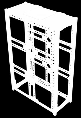
4 3 Overview GomSpace NanoCom ANT2000 is an active antenna specifically designed for interfacing with GomSpace SDR transceivers. Several versions are available depending on usage and placement on a nano-satellite. The active antenna is built as a sandwich around a shield/mounting plate. The RF signal connection between the antenna and electronics PCBs are made with RF compression connectors. This construction allows flexible mounting on several different satellite structures just by changing the shield/mounting plate. Below is shown a CAD of the top and the bottom of the ANT Highlighted Features Integrated antenna and PA/LNA results in low loss and optimum RF performance. Duplex filter based design results in optimum co-existence with other RF transceivers on-board. Flexible sandwich construction allows flexible mounting on different satellite structures just by changing the shield/mounting plate. Shielded electronics. Flexible power interface (8-18 V). Default CAN-bus control interface. Medium gain (8 dbi) patch antenna with circular polarization. ANT2000-ISL-2150 version supports time division duplex (TDD) in MHz frequency band. ANT2000-DUP-2150 version supports full duplex with RX in MHz and TX in MHz. ANT2000-DUP-2090 version supports full duplex with RX in MHz and TX in MHz. Temperature sensors (one sensor for PA and one in the microcontroller). Input current sensor. PCB material: o Electronics Board: Glass/Polyimide IPC 6012C cl. 3 o Antenna Module: Rogers RO4003C IPC-A-610 Class 3 assembly 4


5 3.2 Block Diagram 3.3 Functional Description The ANT2000 contains: a transmit power amplifier, a receive low noise amplifier, transmit/receive switch (ISL version), and necessary support circuits. The antenna section includes matching components and the RF compression connectors. Stated antenna gain includes loss in matching circuit and in the RF connectors. The transmitter chain includes a (pre) driver amplifier stage and a multistage balanced PA. Interstage SAW filters reduce broadband noise and provides stage isolation. The receiver chain contains two LNAs again with interstage SAW filters to protect following stages from out-of-band interference. All performance parameters for the electronics board and for the antenna module are given at the reference plane ISL Version This front-end uses the same frequency band for RX and TX, which allows two ISL radio board to communicate using time division duplex. 5

6 The ISL front-end has a TX/RX switch and uses a bandpass filter (half of duplex-filter) that reduces transmitter noise (broadband) significantly. During production/checkout it can be configured if the antenna should use RHCP or LHCP DUP Version The DUP version is the same as the ISL version except for the TX/RX switch and the filters on the Receiver chain. This version is available for two different frequency bands (see section 4.2). 3.4 Calibration and Setup During production check-out, several calibration values are stored in the board. For the receiver calibration values describe the RX gain at 7 frequencies across the RX band. These values can be used to implement a compensated RSSI function. (Antenna gain is not included). The RSSI values can also be temperature compensated using stored calibration values for gain temperature dependency. The transmitter calibration values are primarily used to setup the correct input power to reach a given output power (compensated for frequency and temperature). One calibration value describes the input power detector level for a -10 dbm center frequency carrier, which will allow the SDR platform to set this level independently of cable loss. All other input levels should be set relative to the calibrated -10 db level. The PA has three predefined bias levels, which are optimized for 2 W, 1 W, and 0.5 W (se chapter 11.3). All levels are setup for approximately -25 dbc adjacent channel power for a 500 ksymbol/s QPSK a (RC 0.35) modulated signal. 6
7 4 Versions When ordering the customer has to make a choice of: PCB version ANT2000-ISL-2150, ANT2000-DUP-2150 or ANT2000-DUP-2090 Antenna polarization (ISL default LHCP and DUP default RHCP) Mounting plate - depends on where the antenna is to be mounted Profile height a special low profile of the antenna is available for the ISL version 4.1 Inter Satellite Link (ISL) and Profile ANT2000-ISL-2150 Unit TX band MHz RX band MHz The ISL antenna module version comes with either a standard profile or a low profile. The low profile is intended for type D mounting (see chapter 4.3). 4.2 Duplex (DUP) and Profile DUP comes in two versions. ANT2000-DUP-2150 ANT2000-DUP-2090 Unit TX band MHz RX band MHz The DUP is only available in the standard profile version. 4.3 Mounting Plate Four different mounting plates are available, depending on where the ANT2000 is placed on a nanosatellite. They are all 1.5 mm aluminum. The 3U is used as an example; the plates can also be mounted on 1U and 2U nano-satellite. Z D C B A B A X Y GomSpace 6U structure 3U structure 7


8 Type A Type B Used in a 3U structure on the A-sides and on the 6U structure A-sides. Type C Used in 3U structure on the B-sides. Type D Used in the top or bottom of a 3U structure and not exceed the height of the structure rails. Designed for use with the GomSpace NanoCom ANT-6F, which is mounted on the top or bottom of a 6U structure and not exceeds the height of the structure rails. 8


9 5 Connector Pinout 5.1 Connector Location Top J J J401 1 J J J102 - RX RF COAXIAL CONNECTOR Molex SSMCX Pin Name Description 1 RX RF Amplified received signal 2 GND J300 - TX RF COAXIAL CONNECTOR Molex SSMCX Pin Name Description 1 TX RF Transmitter input signal 2 GND 9
10 5.1.3 J400 - Power Connector Molex Pico-Lock 1.50 mm pitch Pin Name Description 1 AABON Low < 0.4 V, Active High > 2.5 V (max 18V) 2 GND 3 GND 4 GND 5 VIN 8 18 V externally switchable 6 VIN 8 18 V externally switchable 7 VIN 8 18 V externally switchable J401 - Control Connector Molex Pico-Lock 1.50 mm pitch Pin Name Description 1 n.c. 2 GND 3 I2C_SCL I 2 C backup communication bus (not supported by current firmware) 4 I2C_SDA I 2 C backup communication bus (not supported by current firmware) 5 CANL CAN bus (ATSAM21C series MCU used) 6 CANH CAN bus (ATSAM21C series MCU used) 7 GND 8 TXEN_EX Select TX mode in manual duplex mode 9 TXON_EX Power on TX circuit 10 RXON_EX Power on RX circuit J402 - Debug Molex Pico-Lock 1.50 mm pitch Pin Name Description 1 GND 2 UART RX GOSH serial communication 3 UART TX GOSH serial communication 4 SWCLK Firmware upload/debug 5 SWDIO Firmware upload/debug 6 RESETn Firmware upload/debug 10
11 6 Data Interface The NanoCom ANT2000 uses the CubeSat Space Protocol (CSP) to transfer data to and from CSP nodes on-board the main system bus. CSP is a routed network protocol that can be used to transmit data packets between individual subsystems on the satellite bus and between the satellite and ground station. For more information about CSP please read the documentation on libcsp.org and on Wikipedia: Default control interface is a CAN-bus. I 2 C is being implemented later. 7 Debug Interface The debug interface is a USART that uses the GomSpace Shell (GOSH) to present a console-like interface to the user. GOSH is a general feature present on all GomSpace products. The console can be used during checkout and satellite integration of the ANT2000 to send commands and inspect/set parameters. 8 Absolute Maximum Ratings Stresses above those listed under Absolute Maximum Ratings may cause permanent damage to the ANT2000. Exposure to absolute maximum rating conditions for extended periods may affect the reliability. Symbol Description Min. Max. Unit VIN Input Supply voltage V PIN Supply power draw - 11 W P in Absolute maximum input power at 5 dbm TX and RX ports T amb Operating Temperature C T stg Storage Temperature C 9 Electrical Characteristics Symbol Description Min. Max. Unit P sup_off Supply power, OFF mw P sup_idle Supply power, IDLE mw P sup_rx Supply power, RX mode mw P sup_tx Supply power, TX STANDBY mw P sup_tx Supply power, TX ACTIVE mw 10 Physical Characteristics Description Value Unit Mass (approximate depends on mounting etc) ~ 110 g Size (see chapter 13) 98 x 98 x 20.1 mm 11
12 11 RF Performance Characteristics 11.1 Receiver ISL Symbol Description Min. Max. Unit Gain,rx RX Avg. Gain, 25 C db Gain ripple 25 C -3 3 db Gain ripple -40 C to 85 C -3-3 db NF,rx RX Noise Figure, 25 C 2.5 (typ) 2.8 db RX Noise Figure, -40 C to 85 C 3.5 db Freq, rx RX frequency band MHz 11.2 Receiver DUP Symbol Description Min. Max. Unit Gain,rx RX Avg. Gain, 25 C db Gain ripple 25 C -4 4 db Gain ripple -40 C to 85 C -5-5 db NF,rx RX Noise Figure, 25 C 2.0 (typical) 2.2 db RX Noise Figure, -40 C to 85 C 2.8 Freq, rx RX band (ANT-2150-DUP) MHz RX band (ANT-2090-DUP) MHz 11.3 Transmitter Symbol Description Min. Max. Unit Pow.level 2 Pout 32.0 (typ) dbm Pout ripple db Pin (typical) -8-4 dbm DC Power (typical) (Vin 10V) W Pow.level 1 Pout 29.8 (typ) dbm Pout ripple db Pin (typical) dbm DC Power (typical) (Vin 10V) W Pow.level 0 Pout 26.8 (typ) dbm Pout ripple db Pin (typical) dbm DC Power (typical) (Vin 10V) W Pin,thr Threshold for input detector rising -28 dbm Pin,thr,hys Hysteresis for input power det. 2 db Pout,min Min. power for automatic TX Pin: -26 Pout: 14 dbm 12

13 12 Antenna Performance Figure below is a typical simulated radiation pattern, and a definition of the Phi and Theta angles used to describe the general antenna performance. The antenna module includes connectors and matching circuit and has two feed ports which must be driven 90 out of phase to generate a circular polarized radiation. On the electronics board a hybrid coupler generates the necessary quadrature signals. For the antenna measurements an adaptor board with the same hybrid coupler is used as test interface and the adaptor board loss (~0.30 db) is compensated in the measurements. Due to symmetry of the feed ports both circular polarizations will have the same performance and the results shown in this section with be based on RHCP data. 13
14 12.1 Standard Profile Antenna Gain All antenna radiation measurements are with a Satimo Ring setup using a 98 x 98 mm aluminum ground plane. Below antenna gain (including connector) and radiation pattern for Phi=45 (diagonal across ground plane) is shown Antenna Gain dbi MHz AM2150 STD, Phi 45 cut, Gain [dbi] vs. Theta 10 5 dbi RHG 1980 RHG 2010 RHG 2025 RHG 2065 RHG 2110 RHG 2170 RHG 2200 RHG Theta [ ] 14
15 Axial ratio All ANT2000 antennas are circular polarized, and product polarization is determined by the electronics PCB. Below the maximum axial ratio for elevation is shown as a function of frequency, and the axial ratio as a function of Theta for a Phi angle of 45. As seen the axial ratio is quite good within the halfpower beamwidth. db Antenna Axial Ratio (max for Theta ±40 ) MHz 30.0 AM2150 STD, Phi 45 cut, Axial Ratio [db] vs. Theta 25.0 db AR 1980 AR 2010 AR 2025 AR 2065 AR 2110 AR 2170 AR 2200 AR Theta [ ] 15
16 Half Power Beamwidth Antenna Half Power Beamwidth degrees MHz Port Matching ANT2150-STD EM#1 Port Matching db Freq [MHz] S11 db S22 db BAND 16
17 12.2 Low Profile Only the ANT2000-ISL-2150 in the MHz frequency band can use the low profile antenna. The Half power beamwidth and the axial ration is virtually the same as for the standard antenna Antenna Gain Performance within this band is marginally lower than the standard antenna primarily due to matching losses. Below the gain [dbi] is shown in comparison with the standard profile antenna Antenna Gain dbi MHz RH STD RH LP Port Matching The matching of the ports is significantly more narrowband than the standard antenna as shown below. db ANT2150-LP EM#1 Port Matching Freq [MHz] S11 db S22 db BAND 17
18 MFG BPX Datasheet 4 13 Mechanical Drawing All dimensions in mm Type A DRAWN jal CHECKED QA
19 Type B 3 2 4x DRAWN jal CHECKED QA MFG 19 APPROVED
20 Type C 3 2 4x DRAWN jal 03-0 CHECKED QA MFG APPROVED
21 Type D x ø DRAWN jal CHECKED QA MFG APPROVED
Datasheet VHF antenna and release system for GomSpace 6U structure
 NanoCom ANT-6F VHF NanoUtil AR6 Datasheet VHF antenna and release system for GomSpace 6U structure 1 Table of Contents 1 TABLE OF CONTENTS... 2 2 INTRODUCTION... 4 3 OVERVIEW ANT-6F VHF... 5 3.1 HIGHLIGHTED
NanoCom TR-600. Datasheet Nano-satellite transceiver
 NanoCom TR-600 Datasheet Nano-satellite transceiver 1 Table of Contents 1 TABLE OF CONTENTS... 2 2 OVERVIEW... 3 2.1 HIGHLIGHTED FEATURES... 3 2.2 BLOCK DIAGRAM... 4 2.3 AD9361 TRANSCEIVER DATASHEET...
NanoCom ANT430. Datasheet 70 cm band Omnidirectional UHF CubeSat antenna
 NanoCom ANT430 Datasheet 70 cm band Omnidirectional UHF CubeSat antenna 1 Table of Contents 1 TABLE OF CONTENTS... 2 2 OVERVIEW... 3 2.1 HIGHLIGHTED FEATURES... 3 2.2 FUNCTIONAL DESCRIPTION... 3 2.2.1
GAUSS High Power UHF Radio
 [] Table of contents Table of contents... 1 1. Introduction... 3 Features... 4 Block Diagram... 6 2. Pinouts... 7 3. Absolute Maximum Ratings... 9 4. General Recommended Operating Conditions... 10 5. RF
DRC 3500 Versatile Ka-Band Transceiver
 DRC 3500 Key Features: Flexible Polarisation: RHCP/ LHCP and cross/co-polar 2 GHz operation by switchable sub-bands Optimised, integrated Feed-chain for highest EIRP and G/T True 5 Watt P1dB at the Feed
Applications. Operating Modes. Description. Part Number Description Package. Many to one. One to one Broadcast One to many
 RXQ2 - XXX GFSK MULTICHANNEL RADIO TRANSCEIVER Intelligent modem Transceiver Data Rates to 100 kbps Selectable Narrowband Channels Crystal controlled design Supply Voltage 3.3V Serial Data Interface with
Sales Document Description of three SR2000 based solutions offered by GomSpace
 SR2000 HSL, ISL and ASL Solutions NanoCom SR2000 Sales Document Description of three SR2000 based solutions offered by GomSpace 1 Table of Contents 1 TABLE OF CONTENTS... 2 2 GOMSPACE SDR INTRODUCTION...
DATASHEET. X-band Transmitter
 DATASHEET X-band Transmitter 1 Change Log... 3 2 Acronyms List... 4 3 System Overview... 5 4 Features and Benefits... 6 5 RF Characteristics... 6 6 Connectors... 8 6.1 Location... 8 6.2 Pinout: H1 - Stack
RSE02401/00 24 GHz Radar Sensor
 General description The RSE02401/00 is a fully integrated K-band FMCW radar sensor. It utilizes packaged low-cost components, enabling low unit prices and high volumes, using SMT assembly technology, with
DISCONTINUED. Modulation Type Number of RF Channels 15
 RFM Products are now Murata products. 2.4 GHz Spread Spectrum Transceiver Module Small Size, Light Weight, Built-In Antenna Sleep Current less than 3 µa FCC, Canadian IC and ETSI Certified for Unlicensed
G3P-R232. User Manual. Release. 2.06
 G3P-R232 User Manual Release. 2.06 1 INDEX 1. RELEASE HISTORY... 3 1.1. Release 1.01... 3 1.2. Release 2.01... 3 1.3. Release 2.02... 3 1.4. Release 2.03... 3 1.5. Release 2.04... 3 1.6. Release 2.05...
SMARTALPHA RF TRANSCEIVER
 SMARTALPHA RF TRANSCEIVER Intelligent RF Modem Module RF Data Rates to 19200bps Up to 300 metres Range Programmable to 433, 868, or 915MHz Selectable Narrowband RF Channels Crystal Controlled RF Design
GPS RADIONOVA RF Antenna Module
 Product Specification Applications PNDs Portable handheld battery operated GPS enabled devices PDAs Multi-mode mobile phones Smart phones Features Low cost single package GPS RF antenna module SiRF Star
Datasheet High Precision and ultra small vector sun sensor with digital interface
 NanoSense Fine Sun Sensor Datasheet High Precision and ultra small vector sun sensor with digital interface 1 Table of Contents 1 TABLE OF CONTENTS... 2 2 OVERVIEW... 3 2.1 HIGHLIGHTED FEATURES... 3 3
WJM1000. Next Generation RFID Reader Module Based on the WJC200 Gen2 RFID reader chipset. Key Features
 Key Features Multi-protocol support: ISO 18000-6C (Gen2) & ISO 18000-6B Dynamic RF output power: 10dBm to 24dBm range Two antenna ports for added flexibility Special high performance single tag access
INDY R2000 Module Series Specification
 1 Table 1: Module Overview Module Type M-2600 M-2800 Real Photo RF Channel Single Channel Four channel RF Connector MMCX SMA Antenna Connection Mode Can be configured as a single Bistatic is unavailable
INSTALLATION AND OPERATING MANUAL
 INSTALLATION AND OPERATING MANUAL FOR RBDA-PCS-1/25W-90-A INDOOR REPEATER TABLE OF CONTENTS PARAGRAPH PAGE NO BDA OVERVIEW 3 BDA BLOCK DIAGRAM DESCRIPTION 3 FCC INFORMATION FOR USER 3 BDA BLOCK DIAGRAM
DISCONTINUED. Modulation Type Number of RF Channels 15
 RFM products are now Murata Products 2.4 GHz Spread Spectrum Transceiver Module Small Size, Light Weight, Low Cost Sleep Current less than 3 µa FCC, Canadian IC and ETSI Certified for Unlicensed Operation
CMOS 2.4GHZ TRANSMIT/RECEIVE WLAN RFeIC
 CMOS 2.4GHZ TRANSMIT/RECEIVE WLAN RFeIC 17 1 RX 2 3 VDD VDD DNC 16 15 14 13 12 11 10 ANT Description The RFX2402C is a fully integrated, single-chip, single-die RFeIC (RF Front-end Integrated Circuit)
TRXQ1 RXQ1 FM NARROW BAND TRANSCEIVERS. RXQ1 Version. Applications. TRXQ1 Version
 RF Transceiver or Intelligent Modem Versions Host Data Rate upto 19,200 Baud Data Rates to 20 K baud. 2 Selectable RF Channels Narrowband Crystal Controlled Optimal Range 200m Supply Voltage 3-5V Very
Catalogue
 Catalogue 1. Overview... - 3-2. Features... - 3-3. Applications...- 3-4. Electrical Characteristics...- 4-5. Schematic... - 4-6. Speed rate correlation table...- 6-7. Pin definition...- 6-8. Accessories...-
GPS Active Antenna With GPRS Measurement Report
 GPS Active Antenna With GPRS Measurement Report Summary: This report is to account for the measurement setup and results of 4x23mm and mm height GPS active antenna combined with GPRS antenna measurement.
DUAL BAND FM WIRELESS TRANSCEIVER RXQ1. Applications
 FM Radio Transmitter & Receiver Low Profile Ceramic DIL Package Data Rates To 20 Kbits/S 433.92 or 433.33MHz Operation 2 Selectable Channels Narrowband Crystal Controlled Optimal Range 200m Supply Voltage
Doodle Labs WiFi Frequency Shifter xm-915
 Doodle Labs WiFi Frequency Shifter xm-915 Frequency Shifters - Overview Doodle Labs family of Wi-Fi Frequency Shifters (WiFi-FES) provide flexibility to system integrators looking to deploy their existing
Catalog
 - 1 - Catalog 1. Overview... - 3-2. Feature...- 3-3. Application... - 3-4. Block Diagram... - 3-5. Electrical Characteristics...- 4-6. Operation...- 4-1) Power on Reset... - 4-2) Sleep mode...- 4-3) Working
Data Sheet. ACMD-7409 Miniature PCS Band Duplexer. Features. Description. Specifications. Applications. Functional Block Diagram
 ACMD-749 Miniature PCS Band Duplexer Data Sheet Description The Avago ACMD-749 is a miniature duplexer designed for US PCS handsets. The ACMD-749 is designed with Avago Technologies Film Bulk Acoustic
Doodle Labs WiFi Frequency Shifter xm-3600
 Doodle Labs WiFi Frequency Shifter xm-3600 Frequency Shifters - Overview Doodle Labs family of Wi-Fi Frequency Shifters (WiFi-FES) provide flexibility to system integrators looking to deploy their existing
LoRa1276 Catalogue
 Catalogue 1. Overview... 3 2. Features... 3 3. Applications... 3 4. Electrical Characteristics... 4 5. Schematic... 5 6. Speed rate correlation table... 6 7. Pin definition... 6 8. Accessories... 8 9.
Maintenance Manual LBI-38531G MHz, 110 WATT POWER AMPLIFIER 19D902797G1 DESCRIPTION TABLE OF CONTENTS
 Maintenance Manual LBI-38531G 136-174 MHz, 110 WATT POWER AMPLIFIER 19D902797G1 TABLE OF CONTENTS Page DESCRIPTION.............................................. Front Cover SPECIFICATIONS.................................................
Embedded Radio Data Transceiver SV611
 Embedded Radio Data Transceiver SV611 Description SV611 is highly integrated, multi-ports radio data transceiver module. It adopts high performance Silicon Lab Si4432 RF chip. Si4432 has low reception
Catalog
 Catalog 1. Description... - 3-2. Features... - 3-3. Application... - 3-4. Electrical specifications...- 4-5. Schematic... - 4-6. Pin Configuration... - 5-7. Antenna... - 6-8. Mechanical Dimension(Unit:
Doodle Labs Prism-WiFi Transceiver NM-4900 High Performance COFDM/MIMO Broadband Transceiver with minipcie
 Doodle Labs Prism-WiFi Transceiver NM-4900 High Performance COFDM/MIMO Broadband Transceiver with minipcie Prism-WiFi Transceiver Overview Doodle Labs Prism-WiFi are frequency shifted long range Industrial
BK2 Series. STE KSOLUTIONS BK2x DATA SHEET. TABLE 1 PERFORMANCE DATA BK2x RECEIVER SECTION 80 to 650 MHz / 842 to 916 MHz¹ 2FSK GFSK RCFSK 3FSK 4FSK
 BKx BK Series Module Dimensions 33 mm x 5 mm The BKxx series of modules offers a wide choice of frequency band selection: 69 MHz, 35 or 434 MHz, 868 or 95 MHz. The modules are NBFM (Narrow Band Frequency
CMOS 2.4GHZ ZIGBEE/ISM TRANSMIT/RECEIVE RFeIC
 CMOS 2.4GHZ ZIGBEE/ISM TRANSMIT/RECEIVE RFeIC Description 17 1 2 3 4 TXRX VDD VDD D 16 15 14 13 12 11 10 ANT 9 The is a fully integrated, single-chip, single-die RFeIC (RF Front-end Integrated Circuit)
Preliminary Product Overview
 Preliminary Product Overview Features DC to > 3 GHz Frequency Range 25 Watt (CW), 200W (Pulsed) Max Power Handling Low On-State Insertion Loss, typical 0.3 db @ 3 GHz Low On-State Resistance < 0.75 Ω 25dB
ANTENNAFIER TM 915LTX BLOCK DIAGRAM LNA
 Digitally Tunable 0.5 to 10 Watts This 915 LTX is a Outdoor High Power Digitally Tunable Bi-Directional Amplifier for 802.11b/g WLAN. It s tuned and powered over a 50 Ohm coax. Now you can fine tune your
RFFM4503TR7. Features. Applications. Ordering Information. Package: Laminate, 16-pin, 3.0mm x 3.0mm x 1.0mm
 RFFM4503 4.9GHz to 5.85GHz 802.11a/n/ac Wi-Fi Front End Module The RFFM4503 provides a complete integrated solution in a single front end module (FEM) for Wi-Fi 802.11a/n/ac systems. The ultrasmall factor
Advanced RTK GPS / Compass module with 100x100 mm ground plane and 32-bit MCU
 TGM100 Advanced RTK GPS / Compass module with 100x100 mm ground plane and 32-bit MCU Data Sheet Revision: 0.3 Date of Last Revision: 18 April 2017 True Flight Technology, Inc. ( TFT ) reserves the right
HFA GHz - 2.5GHz 250mW Power Amplifier. Description. Features. Applications. Ordering Information. Functional Block Diagram
 SEMICONDUCTOR HFA39 January 1997 2.4GHz - 2.GHz mw Power Amplifier Features Highly Integrated Power Amplifier with T/R Switch Operates Over 2.7V to Supply Voltage High Linear Output Power (P 1dB : +24dBm)
MC-1010 Hardware Design Guide
 MC-1010 Hardware Design Guide Version 1.0 Date: 2013/12/31 1 General Rules for Design-in In order to obtain good GPS performances, there are some rules which require attentions for using MC-1010 GPS module.
Page : 1 / 221 TEST REPORT. Corning Optical Communications Wireless Inc.
 Page : 1 / 221 TEST REPORT Report number Name RAPA15-O-035 Corning Optical Communications Wireless Inc. Applicant Logo Manufacturer Address Name Address 13221 Woodland Park Rd, Suite 400 Herndon, Virginia
AO-1505-THM ZigBee Temperature and Humidity Sensor
 Features Reliable wireless transceiver module. Compatible with Peer to Peer, Star, Tree, or Mesh network configurations. AO-50 with on board PCB ANT with 50M range (LOS). AO-50A with external Antenna.
CMOS 5GHz WLAN ac RFeIC WITH PA, LNA AND SPDT
 CMOS 5GHz WLAN 802.11ac RFeIC WITH PA, LNA AND SPDT RX LEN 16 RXEN ANT 15 14 13 12 11 Description RFX8051 is a highly integrated, single-chip, single-die RFeIC (RF Front-end Integrated Circuit) which incorporates
FM Radio Transmitter & Receiver Modules
 Features Miniature SIL package Fully shielded Data rates up to 128kbits/sec Range up to 300 metres Single supply voltage Industry pin compatible T5-434 Temp range -20 C to +55 C No adjustable components
CMOS 5GHz WLAN ac RFeIC WITH PA, LNA AND SPDT
 CMOS 5GHz WLAN 802.11ac RFeIC WITH PA, LNA AND SPDT RX LEN 16 RXEN ANT 15 14 13 12 11 Description RFX8051B is a highly integrated, single-chip, single-die RFeIC (RF Front-end Integrated Circuit) which
CSR Bluetooth Modules MBC05-CAR-AT
 CSR Bluetooth Modules MBC05-CAR-AT Specification Version 0.1 25-Aug-2009 Product No.: MBC05-CAR-AT Product Description: Bluetooth v2.1 EDR Class 2 BT Stereo Module Issue Date: 2009/08/25 Release Version:
12mm Two Stage 25dB GPS Active Patch Antenna Module with front-end Saw Filter
 AP.12F.7.45A Specification Part No. AP.12F.7.45A Product Name 12mm Two Stage 25dB GPS Active Patch Antenna Module with front-end Saw Filter Feature 13.4*13.4*5.7mm (Ground Plane) 45mm Ø1.13 cable IPEX
3V DUAL MODE TRANSCEIVER 434 MHz BAND Product Code:
 3V DUAL MODE TRANSCEIVER 434 MHz BAND Product Code: 32001269 Rev. 1.6 PRODUCT SUMMARY: Dual-mode transceiver operating in the 434 MHz ISM band with extremely compact dimensions. The module operates as
CMOS 2.4GHZ ZIGBEE/ISM TRANSMIT/RECEIVE RFeIC
 hot RFX2401C CMOS 2.4GHZ ZIGBEE/ISM TRANSMIT/RECEIVE RFeIC Description 1 2 3 4 TXRX 17 VDD VDD DNC 16 15 14 13 12 11 10 ANT 9 The RFX2401C is a fully integrated, single-chip, single-die RFeIC (RF Front-end
Catalog
 - 1 - Catalog 1. Overview...- 3-2. Feature... - 3-3. Application...- 3-4. Block Diagram...- 3-5. Electrical Characteristics... - 4-6. Operation... - 4-1) Power on Reset... - 4-2) Sleep mode... - 4-3) Working
DRA808M 30dBm Wireless Voice Transceiver Module V1.11
 DRA808M 30dBm Wireless Voice Transceiver Module V1.11 Features: Frequency Range: 400~470MHz Tx/Rx frequency independent Channel space: 12.5/25KHz Configurable multi-channels Sensitivity: -122dBm Output
INSTALLATION and OPERATION INSTRUCTIONS. FOR FiberLink BI-DIRECTIONAL AMPLIFIER WITH DIVERSITY MW-FBDA-800AB-50W-DIV
 INSTALLATION and OPERATION INSTRUCTIONS FOR FiberLink BI-DIRECTIONAL AMPLIFIER WITH DIVERSITY MW-FBDA-800AB-50W-DIV Page 1 of 15 TABLE OF CONTENTS PARA No. PARAGRAPH PAGE No. 1. OVERVIEW 3 2. COMPONENT
SV613 USB Interface Wireless Module SV613
 USB Interface Wireless Module SV613 1. Description SV613 is highly-integrated RF module, which adopts high performance Si4432 from Silicon Labs. It comes with USB Interface. SV613 has high sensitivity
Specification AP.25F A. Product Name. 25mm Two Stage GPS Active Patch Antenna Module with front-end Saw Filter. Feature
 AP.25F.07.0078A Specification Part No. AP.25F.07.0078A Product Name 25mm Two Stage GPS Active Patch Antenna Module with front-end Saw Filter Feature Industry leading GPS antenna performance 25mm*25mm*8mm
GHz RF Front-End Module (Low Current) Note: All information provided is subjected to change without prior notice.
 Note: All information provided is subjected to change without prior notice.") Preliminary FM2422 dual-mode 82.11 b/g RF Front-End Module QFN WH378 Rev. 1 2.4-2.5 GHz RF Front-End Module (Low Current) Note: All information provided is subjected to change without prior notice. Product
Preliminary FM2422 dual-mode 82.11 b/g RF Front-End Module QFN WH378 Rev. 1 2.4-2.5 GHz RF Front-End Module (Low Current) Note: All information provided is subjected to change without prior notice. Product
Doodle Labs Prism-WiFi Transceiver NM-4965 High Performance COFDM/MIMO Broadband Transceiver with minipcie
 Doodle Labs Prism-WiFi Transceiver NM-4965 High Performance COFDM/MIMO Broadband Transceiver with minipcie Prism-WiFi Transceiver Overview Doodle Labs Prism-WiFi are frequency shifted long range Industrial
5100 Series L-Band Fiber Optic Links
 LBand Fiber Optic Links The 5100Series fiber optic interfacility links (IFLs) are a high performance, costeffective alternative to coaxial cable for 950 MHz to 2050 MHz LBand satellite communications applications.
Data Sheet. ACMD-7402 Miniature PCS Band Duplexer. Description. Features. Specifications. Applications. Functional Block Diagram
 ACMD-742 Miniature PCS Band Duplexer Data Sheet Description The Avago ACMD-742 is a miniature duplexer designed for US PCS handsets. The ACMD-742 is designed with Avago Technologies Film Bulk Acoustic
User Manual WHM520V. 1. Introduction. 2. Feature
 User Manual 1 Introduction The module is wireless audio module based on AV5100 The AV5100 is 5GHz wireless audio SoC (System-on-chip), optimized for building point to multi-point digital wireless audio
CMOS 2.4GHZ ZIGBEE/ISM TRANSMIT/RECEIVE RFeIC
 CMOS 2.4GHZ ZIGBEE/ISM TRANSMIT/RECEIVE RFeIC Description 17 1 2 3 4 TXRX VDD VDD D 16 15 14 13 12 11 10 ANT 9 The RFX2401C is a fully integrated, single-chip, single-die RFeIC (RF Front-end Integrated
RF Wireless Serial Device Server
 RF-SDS RF Wireless Serial Device Server The RF-SDS subassembly is a radio transceiver acting as a Serial Device Server, which externally connects a remote serial RF transceiver to an Ethernet network (TCP/IP).
GPS/GNSS Front-End Amplifier
 EVALUATION KIT AVAILABLE MAX2678 General Description The MAX2678 GPS/GNSS front-end amplifier IC is designed for automotive and marine GPS/GNSS satellite navigation antenna modules, or for any application
PA FAN PLATE ASSEMBLY 188D6127G1 SYMBOL PART NO. DESCRIPTION. 4 SBS /10 Spring nut. 5 19A702339P510 Screw, thread forming, flat head.
 MAINTENANCE MANUAL 851-870 MHz, 110 WATT POWER AMPLIFIER 19D902797G5 TABLE OF CONTENTS Page DESCRIPTION.............................................. Front Page SPECIFICATIONS.................................................
MC-1612 Hardware Design Guide
 LOCOSYS Technology Inc. MC-1612 Hardware Design Guide Version 1.0 Date: 2013/09/17 LOCOSYS Technology Inc. 1 General Rules for Design-in In order to obtain good GPS performances, there are some rules which
Data Sheet. ACMD-6103 Band 3 Duplexer. Description. Features. Specifications. Applications. Functional Block Diagram
 ACMD-613 Band 3 Duplexer Data Sheet Description The Avago Technologies ACMD-613 is a highly miniaturized duplexer designed for use in LTE Band 3 (171 1785 MHz UL, 185 188 MHz DL) handsets and mobile data
X band downlink for CubeSat
 Eric PERAGIN CNES August 14th, 2012 Existing telemetry systems Downlink systems in UHF or S band derived from HAM protocol and equipments Allow to download few hundred of Mb to 1. Gb per pass Limitation
Features. = +25 C, Vdd = 5V, Vgg1 = Vgg2 = Open
 v3.117 HMC441LM1 Typical Applications The HMC441LM1 is a medium PA for: Point-to-Point Radios Point-to-Multi-Point Radios VSAT LO Driver for HMC Mixers Military EW & ECM Functional Diagram Vgg1, Vgg2:
DC to 1000 MHz IF Gain Block ADL5530
 Data Sheet FEATURES Fixed gain of 16. db Operation up to MHz 37 dbm Output Third-Order Intercept (OIP3) 3 db noise figure Input/output internally matched to Ω Stable temperature and power supply 3 V or
W-CDMA Upconverter and PA Driver with Power Control
 19-2108; Rev 1; 8/03 EVALUATION KIT AVAILABLE W-CDMA Upconverter and PA Driver General Description The upconverter and PA driver IC is designed for emerging ARIB (Japan) and ETSI-UMTS (Europe) W-CDMA applications.
3V TRANSCEIVER 2.4GHz BAND
 3V TRANSCEIVER 2.4GHz BAND Rev. 2 Code: 32001271 QUICK DESCRIPTION: IEEE 802.15.4 compliant transceiver operating in the 2.4 GHz ISM band with extremely compact dimensions. The module operates as an independent
RFX8050: CMOS 5 GHz WLAN ac RFeIC with PA, LNA, and SPDT
 DATA SHEET RFX8050: CMOS 5 GHz WLAN 802.11ac RFeIC with PA, LNA, and SPDT Applications 802.11a/n/ac Smartphones LEN RXEN ANT Tablets/MIDs Gaming Notebook/netbook/ultrabooks Mobile/portable devices RX Consumer
USER MANUAL. UHF Antenna
 USER MANUAL UHF Antenna 1 Change Log... 3 2 Acronyms List... 4 3 Overview... 5 4 Highlighted Features... 5 5 Functional Description... 5 6 Hardware Layout... 5 7 Characteristics... 7 7.1 Frequency... 7
Radiometrix. 433MHz high speed FM radio transceiver module
 NEW NEW NEW NEW Radiometrix Issue E, 13 July 2001 BiM2-433-64 Advanced data is provided to assist in engineering evaluation. The data provided is believed to be accurate but may be subject to change. This
Characteristic Sym Notes Minimum Typical Maximum Units Operating Frequency Range MHz Operating Frequency Tolerance khz
 DEVELOPMENT KIT (Info Click here) 2.4 GHz ZigBee Transceiver Module Small Size, Light Weight, +18 dbm Transmitter Power Sleep Current less than 3 µa FCC and ETSI Certified for Unlicensed Operation The
CHAPTER - 6 PIN DIODE CONTROL CIRCUITS FOR WIRELESS COMMUNICATIONS SYSTEMS
 CHAPTER - 6 PIN DIODE CONTROL CIRCUITS FOR WIRELESS COMMUNICATIONS SYSTEMS 2 NOTES 3 INTRODUCTION PIN DIODE CONTROL CIRCUITS FOR WIRELESS COMMUNICATIONS SYSTEMS Chapter 6 discusses PIN Control Circuits
LR1276 Module Datasheet V1.0
 LR1276 Module Datasheet V1.0 Features LoRaTM Modem 168 db maximum link budget +20 dbm - 100 mw constant RF output vs. V supply +14 dbm high efficiency PA Programmable bit rate up to 300 kbps High sensitivity:
Brushed DC Motor Control. Module with CAN (MDL-BDC24)
") Stellaris Brushed DC Motor Control Module with CAN (MDL-BDC24) Ordering Information Product No. MDL-BDC24 RDK-BDC24 Description Stellaris Brushed DC Motor Control Module with CAN (MDL-BDC24) for Single-Unit
Stellaris Brushed DC Motor Control Module with CAN (MDL-BDC24) Ordering Information Product No. MDL-BDC24 RDK-BDC24 Description Stellaris Brushed DC Motor Control Module with CAN (MDL-BDC24) for Single-Unit
Features. = +25 C, Vdd = 5V, Idd = 85 ma*
 Typical Applications The is an ideal gain block or driver amplifi er for: Point-to-Point Radios Point-to-Multi-Point Radios VSAT Functional Diagram Features Saturated Power: +23 dbm @ 27% PAE Gain: db
915MHz Transmit/Receive Module
 RF6599 915MHz Transmit/Receive Module This module is intended for 915MHz AMR solutions. It provides separate ports for Rx and Tx paths and two ports on the output for connecting a diversity solution or
FCC CFR47 PART 15 SUBPART C INDUSTRY CANADA RSS-GEN AND RSS-210 CERTIFICATION TEST REPORT FOR BROADCOM BLUETOOTH MODULE MODEL NUMBER: BCM92046MD
 FCC CFR47 PART 15 SUBPART C INDUSTRY CANADA RSS-GEN AND RSS-210 CERTIFICATION TEST REPORT FOR BROADCOM BLUETOOTH MODULE MODEL NUMBER: BCM92046MD IC #: 4324A-BRCM1029 REPORT NUMBER: 07U11199-1C ISSUE DATE:
850 MHz Antenna Sharing Combiner ASC850VG12A
 DATA SHEET Small, lightweight, outdoor unit Dual Technology Combiner (GSM 850 / UMTS 850) Can also be used for same technology (e.g. GSM/GSM) Can be used close to Antenna Can be used in Ground Based Applications
17mm Two Stage GPS Active Patch Antenna Module
 AP.7F.7.64A Specification Part No. AP.7F.7.64A Product Name 7mm Two Stage GPS Active Patch Antenna Module Feature 22.2mm*23.8mm*7.8mm 64mm.3 IPEX MHFI Wide Voltage Input.8V to 5.5V 28dB LNA Tested in Free
CMX902 RF Power Amplifier
 CML Microcircuits COMMUNICATION SEMICONDUCTORS RF Power Amplifier Broadband Efficient RF Power Amplifier October 2017 DATASHEET Provisional Information Features Wide operating frequency range 130MHz to
SmartRadio Transmitter / Receiver
 Easy to use Radio Transmitter & Receivers AM Radio Hybrid Technology Supports Data or Telemetry communications Simple CMOS/TTL Data Interface Automatic data encryption / decryption Host Interface up to
PART MAX2265 MAX2266 TOP VIEW. TDMA AT +30dBm. Maxim Integrated Products 1
 19-; Rev 3; 2/1 EVALUATION KIT MANUAL FOLLOWS DATA SHEET 2.7V, Single-Supply, Cellular-Band General Description The // power amplifiers are designed for operation in IS-9-based CDMA, IS-136- based TDMA,
900 MHz Antenna Sharing Combiner ASC900VG11A
 DATA SHEET Small, lightweight, outdoor unit Dual Technology Combiner (GSM 900 / UMTS 900) Can also be used for same technology (e.g. GSM/GSM) Can be used close to Antenna Can be used in Ground Based Applications
Antenna design report for a smart watch
 Antenna design report for a smart watch Krishna Prasad Rao ( krisrao@amazon.com ) S I. INTRODUCTION mart Watches popular in the market usually have, long battery life of up to 3 weeks (10 days in GPS mode),
Data Sheet. ALM GHz GHz 50 Watt High Power SPDT Switch with LNA Module. Features. Description. Specifications.
 ALM-12124 1.88 GHz 2.025 GHz 50 Watt High Power SPDT Switch with LNA Module Data Sheet Description Avago Technologies ALM-12124 is a multi-chip integrated module that comprise of a 50 Watt CW high power
Multi-Channel RS-232 Serial RF Transceiver
 RF-232 Multi-Channel RS-232 Serial RF Transceiver The RF-232 subassembly is a multi-channel serial radio transceiver. This device accepts and outputs standard serial data at one of three selectable data
Specifications and Interfaces
 Specifications and Interfaces Crimson TNG is a wide band, high gain, direct conversion quadrature transceiver and signal processing platform. Using analogue and digital conversion, it is capable of processing
RF ISM Transparent Transceiver Module V4.0
 RF7020-27 ISM Transparent Transceiver Module V4.0 Overview: RF7020-27 is highly integrated semi-duplex medium power transceiver module with high speed MCU and high performance RF IC. Utilizing high efficiency
772D coaxial dual-directional coupler 773D coaxial directional coupler. 775D coaxial dual-directional coupler 776D coaxial dual-directional coupler
 72 772D coaxial dual-directional coupler 773D coaxial directional coupler 775D coaxial dual-directional coupler 776D coaxial dual-directional coupler 777D coaxial dual-directional coupler 778D coaxial
Data Sheet. ALM GHz 2.40 GHz 50 Watt High Power SPDT Switch with LNA Module. Features. Description. Specifications.
 ALM-12224 2.30 GHz 2.40 GHz 50 Watt High Power SPDT Switch with LNA Module Data Sheet Description Avago Technologies ALM-12224 is a multi-chip integrated module that comprise of a 50 Watt CW high power
Revision WI.232FHSS-25-FCC-R and RK-WI.232FHSS-25-FCC-R USER S MANUAL
 Revision 1.0.3 WI.232FHSS-25-FCC-R and RK-WI.232FHSS-25-FCC-R USER S MANUAL RADIOTRONIX, INC. WI.232FHSS-25-FCC-R/ RK-WI.232FHSS-25-FCC-R USER S MANUAL Radiotronix 905 Messenger Lane Moore, Oklahoma 73160
Data Sheet. ACMD-6103 Band 3 Duplexer. Description. Features. Specifications. Applications. Functional Block Diagram
 ACMD-613 Band 3 Duplexer Data Sheet Description The Avago Technologies ACMD-613 is a highly miniaturized duplexer designed for use in LTE Band 3 (171 1785 MHz UL, 185 188 MHz DL) handsets and mobile data
RF4432PRO wireless transceiver module
 wireless transceiver module RF4432PRO 1. Description RF4432PRO adopts Silicon Lab Si4432 RF chip, which is a highly integrated wireless ISM band transceiver chip. Extremely high receive sensitivity (-121
Designing Next-Generation AESA Radar Part 2: Individual Antenna Design
 Design Designing Next-Generation AESA Radar Part 2: Individual Antenna Design Figure 8: Antenna design Specsheet user interface showing the electrical requirements input (a), physical constraints input
Using the TB8100 Base Station as a Talk-Through, Community, or Linked Repeater
 Using the TB8100 Base Station as a Talk-Through, Community, or Linked Repeater Application Note TN-743 1 June 2003 Tait Electronics Ltd Page 1 of 8 558 Wairakei Rd, P.O. Box 1645, Christchurch, New Zealand
SPECIFICATION. Low Profile Stacked Patch Antenna. Highest Accuracy, Lowest Profile Low Axial Ratio. Wideband GNSS Antenna. GPS L1+L2 Band Operation
 SPECIFICATION Patent Pending Part No: GPDF.47.8.A.02 Product Name: Embedded 47.5*47.5*8mm GPS L1/L2 Low Profile Stacked Patch Antenna Features: Highest Accuracy, Lowest Profile Low Axial Ratio Wideband
RFFM8500Q. 4.9GHz to 5.85GHz a/n Front End Module. Features. Applications. Ordering Information
 4.9GHz to 5.85GHz 802.11a/n Front End Module The RFFM8500Q provides a complete integrated solution in a single Front End Module (FEM) for WiFi 802.11a/n systems. The ultra small form factor and integrated