Electronics I lab. DC Power Supply
|
|
|
- Della Weaver
- 6 years ago
- Views:
Transcription


1 Electronics I lab DC Power Supply
2 Objective Design and construct circuits that transform sinusoidal (AC) voltages into constant (DC) voltages. Evaluate the performance of simple rectifier and regulator circuits. Theory: DC power supplies are the essential part of most of the electronic equipments since most of the equipments need DC power for operation. The power which is readily available everywhere is AC (in Gaza 220v/60Hz). DC power supplies convert this AC power into DC that can be used to operate most of our equipments. The main components of a DC power supply are rectifier diodes and capacitors. As you have seen in the last lab that rectifier diodes under normal condition can conduct only in the forward direction. This property of diodes is used to remove (or invert) the negative cycle of the AC voltage so that we have uni-directional voltage but not a constant one. Further, capacitors are used to smoot h out this varying unidirectional voltage and make it as smooth as possible, since capacitor tries to resist the change in its induced voltage, a suitable value of capacitor or a combination of capacitors are used to smooth out the change in the uni-directional voltage and make it constant. The output of the power supply is a fairly smoot h DC voltage. There are 4 main operat ions to mos t powe r supplies: Transfor mer (step do wn the voltage ) Rectification (convert AC to pulsating DC) Filtering (Smooth pulsating DC to reduce peaks and raise valleys) Regulation (Control output voltage level to make it robust against input voltage fluctuations and load changes)

3 Transformer : The power transformer provides separate windings to isolate the primary and secondary circuits. Isolation is necessary for safety considerations. Bizarre accidents are possible with non-isolated systems. A transformer also provides line voltage step down or up as needed by the DC power supply. Using a transformer, voltages can be transformed from one level to another with minimum power loss. All transformers have a voltage rating, frequency rating, and volt-ampere rating, which is the maximum power (real or imaginary) that the secondary can deliver to a load. This rating is a function of the physical size of the iron core. Ideally, the load is resistive and the volt-ampere rating then represents the power in watts. Rectification The rectification process uses diode s to pe rmit current from the transformer in one direction and block reverse current. The alternating current thus becomes unidirectional current known as DC. At this po int the current is in pulses rather than be ing continuo us and s moot h. But there is only one direction of the current thus it is DC.There are three types of rectifier circuits; half-wave, full-wave center-tap, and full-wave bridge. Although we can use four individual power diodes to make a full wave bridge rectifier, pre-made bridge rectifier components are available "off-the-shelf" in a range of different voltage and current sizes that can be soldered directly into a PCB circuit board or be connected by spade connectors. The image to the right shows a typical single phase bridge rectifier with one corner cut off. This cut-off corner indicates that the terminal nearest to the corner is the positive or +ve output terminal or lead with the opposite (diagonal) lead being the negative or -ve output lead. The ot her two connecting leads are for the input alternating voltage from a transformer secondary winding.


4 The Smoothing Capacitor Pulsating DC voltages are generally not useful for electronics. It is preferred to have a relatively constant DC voltage. The filter is frequently just a large capacitance to smooth

5 the raw voltage fluctuations from the rectifier. More advanced designs will include a series inductor in addition to the capacitor for significantly improved filtering and also for improved efficiency in the rectification process. The filter capacitance is usually of the electrolytic type in order to keep the physical size to a minimum. The smoothing capacitor converts the full-wave rippled output of the rectifier into a smooth DC output voltage. Two important parameters to consider when choosing a suitable a capacitor are its Working Voltage, which must be higher tha n the no-load output value of the rectifier and its Capacitance Value, which determines the amount of ripple that will appear superimposed on top of the DC voltage. Too low a value and the capacitor has little effect. As a general rule of thumb, we are looking to have a ripple voltage of less than 100mV peak to peak. Ripple factor : The ipe factor is an indication of the effectiveness of a filter and is defined as r V = V r ( pp ) DC where ( ) r pp V is the peak-to-peak ripple voltage and Vdc is the dc(average )value of the filter's output voltage.the lower the ripple factor the better the filter.the ripple factor can be lowered by increasing the value of the filter capacitor.
6 V V r ( pp ) p ( rect ) frlc DC 1 ( ) V 1 (1 ) V 2fR C l p ( rect ) Surge Current in Capacitor Input Filter When the power is first applied to a power supply, the filter capacitor is uncharged. At the instant the switch is closed, voltage is connected to the rectifier and the uncharged capacitor appears as a short, An initial surge of current is produced through the forward-biased diodes. It is possible that the surge current could destroy the diodes, for this reason a surge-limiting resistor R surge, is sometimes connected. The value of this resistor must be small to avoid a significant voltage drop across it. The diode must have a forward current rating that can ha ndle the momentary surge of current. This rating Is specified in the datasheet of the diode as I FSM R surge V = p (sec) 1.4 I FSM
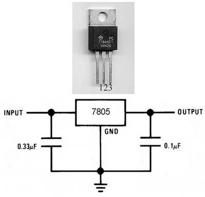
7 Voltage Regulator While filers can reduce the ripple from power supplies to a low value, the most effective a approach is a combination of a capacitor input filter used with a voltage regulator.a voltage regulator is connected to the output of a filtered rectifier and maintains a constant output voltage despite changes in the input,the load current,or the temperature.the capacitor-input filter reduces the input ripple to the regulator to an acceptable level. Most regulators are integrated circuits and have three terminal an input terminal,an output terminal,and a reference terminal.the input to the regulator is first filtered with a capacitor to reduce the ripple to <10%.the regulator reduces the ripple to a negligible amount.in addition,most regulators have an internal voltage reference,short circuit protection. Some common voltages that these are available for include +5, +12,+15,-5,-12, and-15.three-terminal regulator s designed for fixed output voltages require only external capacitors to complete the regulation portion of the power supply.filtering is accomplished by a large value capacitor between the input voltage and ground.an output capacitor (typically.1 uf to 1uF)is connected from output to ground to improve the transient response.

8
9 Worksheet Study the effect of the capacitor 1-Change the value of C1 :1n,100n,1u,50u,100u,470u. For every value compute the ripple factor and plot the output voltage D1 D2 V VOFF = 0 VAMPL = 17 FREQ = 60 V1 V+ C1 R1 D3 V- D4 100u 1k 0 Study the effect of regulator. Plot the output Note : regulator from OPAMP library D1 D2 U1 LM7805C 1 2 IN OUT GND VOFF = 0 VAMPL = 17 FREQ = 60 V1 C1 C2.33u 3 C3.1u R1 1k D3 D4 100u 0

10
Lecture (04) PN Diode applications II
 PN Diode applications II") Lecture (04) PN Diode applications II By: Dr. Ahmed ElShafee ١ Agenda Full wave rectifier, cont.,.. Filters Voltage Regulators ٢ RMS The RMS value of a set of values (or a continuous time waveform) is
Lecture (04) PN Diode applications II By: Dr. Ahmed ElShafee ١ Agenda Full wave rectifier, cont.,.. Filters Voltage Regulators ٢ RMS The RMS value of a set of values (or a continuous time waveform) is
Lecture (03) Diode applications
 Diode applications") Lecture (03) Diode applications By: Dr. Ahmed ElShafee ١ Agenda The Basic DC Power Supply Half wave rectifier Full wave rectifier Filters Voltage Regulators ٢ The Basic DC Power Supply All active electronic
Lecture (03) Diode applications By: Dr. Ahmed ElShafee ١ Agenda The Basic DC Power Supply Half wave rectifier Full wave rectifier Filters Voltage Regulators ٢ The Basic DC Power Supply All active electronic
Lecture (04) Diode applications, cont.
 Diode applications, cont.") Lecture (04) Diode applications, cont. By: Dr. Ahmed ElShafee Agenda Full wave rectifier, cont.,.. Filters Voltage Regulators Diode limiters Diode Clampers ١ ٢ Bridge Full Wave Rectifier Operation uses
Lecture (04) Diode applications, cont. By: Dr. Ahmed ElShafee Agenda Full wave rectifier, cont.,.. Filters Voltage Regulators Diode limiters Diode Clampers ١ ٢ Bridge Full Wave Rectifier Operation uses
Lecture (03) Diodes and Diode Applications I
 Diodes and Diode Applications I") Lecture (03) Diodes and Diode Applications I By: Dr. Ahmed ElShafee ١ Agenda VOLTAGE CURRENT CHARACTERISTIC OF A DIODE Forward bias Reverse Bias V I Characteristic for Forward Bias V I Characteristic for
Lecture (03) Diodes and Diode Applications I By: Dr. Ahmed ElShafee ١ Agenda VOLTAGE CURRENT CHARACTERISTIC OF A DIODE Forward bias Reverse Bias V I Characteristic for Forward Bias V I Characteristic for
Chapter 2. Diodes & Applications
 Chapter 2 Diodes & Applications The Diode A diode is made from a small piece of semiconductor material, usually silicon, in which half is doped as a p region and half is doped as an n region with a pn
RECTIFIERS POWER SUPPLY AND VOLTAGE REGULATION. Rectifier. Basic DC Power Supply. Filter. Regulator
 RECTIFIERS POWER SUPPLY AND OLTAGE REGULATION Prepared by Engr. JP Timola Reference: Electronic Devices by Thomas L. Floyd Because of their ability to conduct current in one direction and block current
ECE 2274 Pre-Lab for Experiment # 4 Diode Basics and a Rectifier Completed Prior to Coming to Lab
 Part I I-V Characteristic Curve ECE 2274 Pre-Lab for Experiment # 4 Diode Basics and a Rectifier Completed Prior to Coming to Lab 1. Construct the circuit shown in figure 4-1. Using a DC Sweep, simulate
Electronic Circuits. Diode Applications. Dr. Manar Mohaisen Office: F208 Department of EECE
 Electronic Circuits Diode Applications Dr. Manar Mohaisen Office: F208 Email: manar.subhi@kut.ac.kr Department of EECE Review of the Precedent Lecture Doping It is a controlled addition of impurities to
Electronic Devices. Floyd. Chapter 2. Ninth Edition. Electronic Devices, 9th edition Thomas L. Floyd
 Electronic Devices Ninth Edition Floyd Chapter 2 Agenda Diode Circuits and Applications Half-wave Rectifier Full-wave Rectifier Power Supply Filter Power Supply Regulator Diode Limiting Circuits Diode
CHAPTER 5: REGULATED DC POWER SUPPLY
 CHAPTER 5: REGULATED DC POWER SUPPLY Dr. Wan Mahani Hafizah binti Wan Mahmud Topics in Chapter 5 5.0Introduction 5.1Rectifier 5.2Filter 5.3oltage Regulator 5.4Switching Regulator 2 Power Supply Block Diagram
VTU NOTES QUESTION PAPERS NEWS RESULTS FORUMS TESTING OF HALF WAVE, FULL WAVE AND BRIDGE RECTIFIERS WITH AND WITHOUT CAPACITOR
 TESTING OF HALF WAVE, FULL WAVE AND BRIDGE RECTIFIERS WITH AND WITHOUT CAPACITOR Aim: To determine the ripple factor, efficiency and regulation of the half wave, full wave and bridge rectifier circuits
EE320L Electronics I. Laboratory. Laboratory Exercise #4. Diode Rectifiers and Power Supply Circuits. Angsuman Roy
 EE320L Electronics I Laboratory Laboratory Exercise #4 Diode Rectifiers and Power Supply Circuits By Angsuman Roy Department of Electrical and Computer Engineering University of Nevada, Las Vegas Objective:
EXPERIMENT 5 : DIODES AND RECTIFICATION
 EXPERIMENT 5 : DIODES AND RECTIFICATION Component List Resistors, one of each o 2 1010W o 1 1k o 1 10k 4 1N4004 (Imax = 1A, PIV = 400V) Diodes Center tap transformer (35.6Vpp, 12.6 VRMS) 100 F Electrolytic
University of Pittsburgh
 University of Pittsburgh Experiment #5 Lab Report Diode Applications and PSPICE Introduction Submission Date: 10/10/2017 Instructors: Dr. Minhee Yun John Erickson Yanhao Du Submitted By: Nick Haver & Alex
An Introduction to Rectifier Circuits
 TRADEMARK OF INNOVATION An Introduction to Rectifier Circuits An important application of the diode is one that takes place in the design of the rectifier circuit. Simply put, this circuit converts alternating
CHAPTER 2. Diode Applications
 CHAPTER 2 Diode Applications 1 Objectives Explain and analyze the operation of both half and full wave rectifiers Explain and analyze filters and regulators and their characteristics Explain and analyze
After performing this experiment, you should be able to:
 Objectives: After performing this experiment, you should be able to: Demonstrate the strengths and weaknesses of the two basic rectifier circuits. Draw the output waveforms for the two basic rectifier
EXPERIMENT 5 : THE DIODE
 EXPERIMENT 5 : THE DIODE Equipment List Dual Channel Oscilloscope R, 330, 1k, 10k resistors P, Tri-Power Supply V, 2x Multimeters D, 4x 1N4004: I max = 1A, PIV = 400V Silicon Diode P 2 35.6V pp (12.6 V
UNIVERSITY OF NORTH CAROLINA AT CHARLOTTE. Department of Electrical and Computer Engineering
 UNIVERSITY OF NORTH CAROLINA AT CHARLOTTE Department of Electrical and Computer Engineering Experiment No. 2 - Semiconductor Diodes Overview: In this lab session students will investigate I-V characteristics
Chapter 1 Introduction to Electronics
 Chapter 1 Introduction to Electronics Section 1-1 Atomic Structure 1. An atom with an atomic number of 6 has 6 electrons and 6 protons.. The third shell of an atom can have n = (3) = 18 electrons. Section
EXPERIMENT 5 : THE DIODE
 EXPERIMENT 5 : THE DIODE Component List Resistors, one of each o 1 10 10W o 1 1k o 1 10k 4 1N4004 (Imax = 1A, PIV = 400V) Diodes Center tap transformer (35.6Vpp, 12.6 VRMS) 100 F Electrolytic Capacitor
Electronics for Analog Signal Processing - I Prof. K. Radhakrishna Rao Department of Electrical Engineering Indian Institute of Technology - Madras
 Electronics for Analog Signal Processing - I Prof. K. Radhakrishna Rao Department of Electrical Engineering Indian Institute of Technology - Madras Lecture - 6 Full Wave Rectifier and Peak Detector In
Diodes & Rectifiers Nafees Ahamad
 Diodes & Rectifiers Nafees Ahamad Asstt. Prof., EECE Deptt, DIT University, Dehradun Website: www.eedofdit.weebly.com 1 Diodes Electronic devices created by bringing together a p-type and n-type region
EXPERIMENT 5 : THE DIODE
 EXPERIMENT 5 : THE DIODE Component List Resistors, one of each o 1 10 10W o 1 1k o 1 10k 4 1N4004 (I max = 1A, PIV = 400V) Diodes Center tap transformer (35.6V pp, 12.6 V RMS ) 100 F Electrolytic Capacitor
Experiment #2 Half Wave Rectifier
 PURPOSE: ELECTRONICS 224 ETR620S Experiment #2 Half Wave Rectifier This laboratory session acquaints you with the operation of a diode power supply. You will study the operation of half-wave and the effect
3.4. Operation in the Reverse Breakdown
 3.4. peration in the Reverse Breakdown Under certain circumstances, diodes may be intentionally used in the reverse breakdown region These are referred to as Zener Diode or Breakdown Diode Voltage regulator
EE 2212 EXPERIMENT 3 3 October 2013 Diode I D -V D Measurements and Half Wave and Full Wave Bridge Rectifiers PURPOSE
 EE 2212 EXPERIMENT 3 3 October 2013 Diode I D -V D Measurements and Half Wave and Full Wave Bridge Rectifiers PURPOSE Use laboratory measurements to extract key diode model parameters including I S,n (also
EXPERIMENT 3 Half-Wave and Full-Wave Rectification
 Name & Surname: ID: Date: EXPERIMENT 3 Half-Wave and Full-Wave Rectification Objective To calculate, compare, draw, and measure the DC output voltages of half-wave and full-wave rectifier circuits. Tools
Sheet 2 Diodes. ECE335: Electronic Engineering Fall Ain Shams University Faculty of Engineering. Problem (1) Draw the
 Draw the") Ain Shams University Faculty of Engineering ECE335: Electronic Engineering Fall 2014 Sheet 2 Diodes Problem (1) Draw the i) Charge density distribution, ii) Electric field distribution iii) Potential distribution,
Ain Shams University Faculty of Engineering ECE335: Electronic Engineering Fall 2014 Sheet 2 Diodes Problem (1) Draw the i) Charge density distribution, ii) Electric field distribution iii) Potential distribution,
Electronic Circuits I Laboratory 03 Rectifiers
 Electronic Circuits I Laboratory 03 Rectifiers # Student ID Student Name Grade (10) 1 Instructor signature 2 3 4 5 Delivery Date -1 / 18 - Objectives In this experiment, you will get to know a group of
Problem 1: Voltage Limiting 1.1. Simulate the following simple resistor-diode circuit (shown on the left in Figure 1):
:") EEE 33 Electronics I (Summer 218) PSPICE: Diode Applications Diode Limiters, Rectifiers and Voltage Regulation (Due Tuesday, June 26, 218) Homework 2 Problem 1: Voltage Limiting 1.1. Simulate the following
EEE 33 Electronics I (Summer 218) PSPICE: Diode Applications Diode Limiters, Rectifiers and Voltage Regulation (Due Tuesday, June 26, 218) Homework 2 Problem 1: Voltage Limiting 1.1. Simulate the following
EXPERIMENT 6: THE ZENER DIODE AND REGULATION
 EXPERIMENT 6: THE ZENER DIODE AND REGULATION Equipment List P 3 Full Wave Bridge OR 4x 1N4004 Diodes. OS BK 2120B Dual Channel Oscilloscope 100 F Electrolytic capacitor I Watt 8.2V Zener Diode R 5 Cenco
Basic Electronic Devices and Circuits EE 111 Electrical Engineering Majmaah University 2 nd Semester 1432/1433 H. Chapter 2. Diodes and Applications
 Basic Electronic Devices and Circuits EE 111 Electrical Engineering Majmaah University 2 nd Semester 1432/1433 H Chapter 2 Diodes and Applications 1 Diodes A diode is a semiconductor device with a single
EE3301 Experiment 5 A BRIDGE RECTIFIER POWER SUPPLY
 Fall 2000 Releant sections of textbook: Chapter 10 Output Stages and Power Supplies 10.5 inear oltage regulators 10.6 inear-power-supply design EE3301 Experiment 5 A BRIDGE RECTIFIER POWER SUPPY 1 Introduction
Diodes and Applications
 Diodes and Applications Diodes and Applications 2 1 Diode Operation 2 2 Voltage-Current (V-I) Characteristics 2 3 Diode Models 2 4 Half-Wave Rectifiers 2 5 Full-Wave Rectifiers 2 6 Power Supply Filters
EE351 Laboratory Exercise 1 Diode Circuits
 revised July 19, 2009 The purpose of this laboratory exercise is to gain experience and understanding working with diodes. Focus on taking good data so that the plots and calculations you will do later
Federal Urdu University of Arts, Science & Technology Islamabad Pakistan SECOND SEMESTER ELECTRONICS - I
 SECOND SEMESTER ELECTRONICS - I BASIC ELECTRICAL & ELECTRONICS LAB DEPARTMENT OF ELECTRICAL ENGINEERING Prepared By: Checked By: Approved By: Engr. Yousaf Hameed Engr. M.Nasim Khan Dr.Noman Jafri Lecturer
Diode Applications 1
 Diode Applications 1 Explain and analyze the operation of both half and full wave rectifiers Explain and analyze filters and regulators and their characteristics Explain and analyze the operation of diode
Ac to dc rectifier calculator
 Ac to dc rectifier calculator output will be a DC with 1.4Volts less than the applied DC voltage. The instantaneous value of the voltage applied to the rectifier is given as. Does a sound mimicked by a
ENGR-2300 Electronic Instrumentation Quiz 4 Fall 2012 Name
 ENGR-23 Quiz 4 Fall 212 ENGR-23 Electronic Instrumentation Quiz 4 Fall 212 Name Question I (25 points) Question II (25 points) Question III (25 points) Question IV (25 points) Total (1 points) On all questions:
Spring Diodes (25 points) In the figure below, each of the diodes turns on at between 0.7 volts and R=2k.
 In the figure below, each of the diodes turns on at between 0.7 volts and R=2k.") Spring 2002 2. Diodes (25 points) In the figure below, each of the diodes turns on at between 0.7 volts and R=2k. 1. Give the voltage at out for each of the following values of the input voltage, in (2
Spring 2002 2. Diodes (25 points) In the figure below, each of the diodes turns on at between 0.7 volts and R=2k. 1. Give the voltage at out for each of the following values of the input voltage, in (2
EXPERIMENT 7: DIODE CHARACTERISTICS AND CIRCUITS 10/24/10
 DIODE CHARACTERISTICS AND CIRCUITS EXPERIMENT 7: DIODE CHARACTERISTICS AND CIRCUITS 10/24/10 In this experiment we will measure the I vs V characteristics of Si, Ge, and Zener p-n junction diodes, and
ECE 2274 Diode Basics and a Rectifier Completed Prior to Coming to Lab
 ECE 2274 Diode Basics and a Rectifier Completed Prior to Coming to Lab Perlab: Part I I-V Characteristic Curve for the 1. Construct the circuit shown in figure 1. Using a DC Sweep, simulate in LTspice
Electro - Principles I
 Page 12-1 The Basic Power Supply The Power Supply The power supply is used to convert the AC energy provided by the wall outlet to dc energy. In most electronic equipment, the power cord supplies the ac
Unregulated Power Supply Tutorial
 Unregulated Power Supply Tutorial Unregulated Power Supply Tutorial: Hey! Why is my 9V wall-wart outputting 14V?! There are a few possible reasons for this. We've also written this tutorial to show you
ENGR4300 Fall 2005 Test 4A. Name solutions. Section. Question 1 (25 points) Question 2 (25 points) Question 3 (25 points) Question 4 (25 points)
 Question 2 (25 points) Question 3 (25 points) Question 4 (25 points)") ENGR4300 Fall 2005 Test 4A Name solutions Section Question 1 (25 points) Question 2 (25 points) Question 3 (25 points) Question 4 (25 points) Total (100 points): Please do not write on the crib sheets.
ENGR4300 Fall 2005 Test 4A Name solutions Section Question 1 (25 points) Question 2 (25 points) Question 3 (25 points) Question 4 (25 points) Total (100 points): Please do not write on the crib sheets.
Diode Bridges. Book page
 Diode Bridges Book page 450-454 Rectification The process of converting an ac supply into dc is called rectification The device that carries this out is called a rectifier Half wave rectifier only half
(A) im (B) im (C)0.5 im (D) im.
 im (B) im (C)0.5 im (D) im.") Dr. Mahalingam College of Engineering and Technology, Pollachi. (An Autonomous Institution affiliated to Anna University) Regulation 2014 Fourth Semester Electrical and Electronics Engineering 141EE0404
Dr. Mahalingam College of Engineering and Technology, Pollachi. (An Autonomous Institution affiliated to Anna University) Regulation 2014 Fourth Semester Electrical and Electronics Engineering 141EE0404
CHAPTER 4 FULL WAVE RECTIFIER. AC DC Conversion
 CHAPTER 4 FULL WAVE RECTIFIER AC DC Conversion SINGLE PHASE FULL-WAVE RECTIFIER The objective of a full wave rectifier is to produce a voltage or current which is purely dc or has some specified dc component.
Exercise 1: EXERCISE OBJECTIVE DISCUSSION. a. circuit A. b. circuit B. Festo Didactic P0 75
 Exercise 1: EXERCISE OBJECTIVE DISCUSSION a. circuit A. b. circuit B. Festo Didactic 91564-P0 75 individual diodes are designated D instead of CR, with the diode circle symbol omitted.) The input terminals
2) The larger the ripple voltage, the better the filter. 2) 3) Clamping circuits use capacitors and diodes to add a dc level to a waveform.
 The larger the ripple voltage, the better the filter. 2) 3) Clamping circuits use capacitors and diodes to add a dc level to a waveform.") TRUE/FALSE. Write 'T' if the statement is true and 'F' if the statement is false. 1) A diode conducts current when forward-biased and blocks current when reverse-biased. 1) 2) The larger the ripple voltage,
TRUE/FALSE. Write 'T' if the statement is true and 'F' if the statement is false. 1) A diode conducts current when forward-biased and blocks current when reverse-biased. 1) 2) The larger the ripple voltage,
Experiment DC-DC converter
 POWER ELECTRONIC LAB Experiment-7-8-9 DC-DC converter Power Electronics Lab Ali Shafique, Ijhar Khan, Dr. Syed Abdul Rahman Kashif 10/11/2015 This manual needs to be completed before the mid-term examination.
Lecture 3 Diodes & Applications :Outline
 Lecture 3 Diodes & Applications :Outline Introduction Diode biasing Diode model Testing a diode Diode application: Rectifiers Diode application: Voltage multipliers Diode application: Optoelectronics 1
3. Diode, Rectifiers, and Power Supplies
 3. Diode, Rectifiers, and Power Supplies Semiconductor diodes are active devices which are extremely important for various electrical and electronic circuits. Diodes are active non-linear circuit elements
Başkent University Department of Electrical and Electronics Engineering EEM 214 Electronics I Experiment 2. Diode Rectifier Circuits
 Başkent University Department of Electrical and Electronics Engineering EEM 214 Electronics I Experiment 2 Diode Rectifier Circuits Aim: The purpose of this experiment is to become familiar with the use
1. An engineer measures the (step response) rise time of an amplifier as. Estimate the 3-dB bandwidth of the amplifier. (2 points)
 rise time of an amplifier as. Estimate the 3-dB bandwidth of the amplifier. (2 points)") Exam 1 Name: Score /60 Question 1 Short Takes 1 point each unless noted otherwise. 1. An engineer measures the (step response) rise time of an amplifier as. Estimate the 3-dB bandwidth of the amplifier.
Exam 1 Name: Score /60 Question 1 Short Takes 1 point each unless noted otherwise. 1. An engineer measures the (step response) rise time of an amplifier as. Estimate the 3-dB bandwidth of the amplifier.
ENGR-4300 Fall 2008 Test 4. Name SOLUTION. Section 1(MR 8:00) 2(TF 2:00) (circle one) Question I (20 points) Question II (20 points)
 2(TF 2:00) (circle one) Question I (20 points) Question II (20 points)") ENGR-43 Fall 28 Test 4 Name SOLUTION Section 1(MR 8:) 2(TF 2:) (circle one) Question I (2 points) Question II (2 points) Question III (15 points) Question IV (2 points) Question V (25 points) Total (1
ENGR-43 Fall 28 Test 4 Name SOLUTION Section 1(MR 8:) 2(TF 2:) (circle one) Question I (2 points) Question II (2 points) Question III (15 points) Question IV (2 points) Question V (25 points) Total (1
ENGR4300 Fall 2005 Test 4A. Name. Section. Question 1 (25 points) Question 2 (25 points) Question 3 (25 points) Question 4 (25 points)
 Question 2 (25 points) Question 3 (25 points) Question 4 (25 points)") ENGR4300 Fall 2005 Test 4A Name Section Question 1 (25 points) Question 2 (25 points) Question 3 (25 points) Question 4 (25 points) Total (100 points): Please do not write on the crib sheets. On all questions:
ENGR4300 Fall 2005 Test 4A Name Section Question 1 (25 points) Question 2 (25 points) Question 3 (25 points) Question 4 (25 points) Total (100 points): Please do not write on the crib sheets. On all questions:
Circuit operation Let s look at the operation of this single diode rectifier when connected across an alternating voltage source v s.
 Diode Rectifier Circuits One of the important applications of a semiconductor diode is in rectification of AC signals to DC. Diodes are very commonly used for obtaining DC voltage supplies from the readily
CHAPTER 1 DIODE CIRCUITS. Semiconductor act differently to DC and AC currents
 CHAPTER 1 DIODE CIRCUITS Resistance levels Semiconductor act differently to DC and AC currents There are three types of resistances 1. DC or static resistance The application of DC voltage to a circuit
CRO AIM:- To study the use of Cathode Ray Oscilloscope (CRO).
.") 1. 1 To study CRO. CRO AIM:- To study the use of Cathode Ray Oscilloscope (CRO). Apparatus: - C.R.O, Connecting probe (BNC cable). Theory:An CRO is easily the most useful instrument available for testing
1. 1 To study CRO. CRO AIM:- To study the use of Cathode Ray Oscilloscope (CRO). Apparatus: - C.R.O, Connecting probe (BNC cable). Theory:An CRO is easily the most useful instrument available for testing
DC Power Supply Design
 Sopczynski 1 John Sopczynski EE 310 Section 4 DC Power Supply Design Introduction The goal of this experiment was to design a DC power supply. Our team would be receiving 120 Vrms oscillating at 60 Hz
Exercise 3: EXERCISE OBJECTIVE
 Exercise 3: EXERCISE OBJECTIVE voltage equal to double the peak ac input voltage by using a voltage doubler circuit. You will verify your results with a multimeter and an oscilloscope. DISCUSSION times
DEPARTMENT OF ELECTRICAL ENGINEERING LAB WORK EE301 ELECTRONIC CIRCUITS
 DEPARTMENT OF ELECTRICAL ENGINEERING LAB WORK EE301 ELECTRONIC CIRCUITS EXPERIMENT : 1 TITLE : Half-Wave Rectifier & Filter OUTCOME : Upon completion of this unit, the student should be able to: i. Construct
SIMULATION DESIGN TOOL LABORATORY MANUAL
 SHANKERSINH VAGHELA BAPU INSTITUTE OF TECHNOLOGY SIMULATION DESIGN TOOL LABORATORY MANUAL B.E. 4 th SEMESTER-2015-16 SHANKERSINH VAGHELA BAPU INSTITUTE OF TECHNOLOGY Gandhinagar-Mansa Road, PO. Vasan,
Secondary school of electrical engineering. present
 Secondary school of electrical engineering Vlastimil Šetka, Zdeněk k Franče, Jakub Tichý,, Lucie Halasová, Petr Časta, Michal PánovecP present Proposition of power supply The first information, which we
ENGR4300 Test 3A Fall 2002
 1. 555 Timer (20 points) Figure 1: 555 Timer Circuit For the 555 timer circuit in Figure 1, find the following values for R1 = 1K, R2 = 2K, C1 = 0.1uF. Show all work. a) (4 points) T1: b) (4 points) T2:
Power Supplies and Circuits. Bill Sheets K2MQJ Rudolf F. Graf KA2CWL
 Power Supplies and Circuits Bill Sheets K2MQJ Rudolf F. Graf KA2CWL The power supply is an often neglected important item for any electronics experimenter. No one seems to get very excited about mundane
Basic DC Power Supply
 Basic DC Power Supply Equipment: 1. Analog Oscilloscope 2. Digital multimeter 3. Experimental board and connectors. Objectives: 1. To understand the basic DC power supply both half wave and full wave rectifier.
CHAPTER 2 A SERIES PARALLEL RESONANT CONVERTER WITH OPEN LOOP CONTROL
 14 CHAPTER 2 A SERIES PARALLEL RESONANT CONVERTER WITH OPEN LOOP CONTROL 2.1 INTRODUCTION Power electronics devices have many advantages over the traditional power devices in many aspects such as converting
transformer rectifiers
 Power supply mini-project This week, we finish up 201 lab with a short mini-project. We will build a bipolar power supply and use it to power a simple amplifier circuit. 1. power supply block diagram Figure
Lecture 7: Diode Rectifier Circuits (Half Cycle, Full Cycle, and Bridge).
.") Whites, EE 320 Lecture 7 Page 1 of 9 Lecture 7: Diode Rectifier Circuits (Half Cycle, Full Cycle, and Bridge). We saw in the previous lecture that Zener diodes can be used in circuits that provide (1)
Whites, EE 320 Lecture 7 Page 1 of 9 Lecture 7: Diode Rectifier Circuits (Half Cycle, Full Cycle, and Bridge). We saw in the previous lecture that Zener diodes can be used in circuits that provide (1)
Industrial Electricity. Answer questions and/or record measurements in the spaces provided.
 Industrial Electricity Lab 10: Building a Basic Power Supply ame Due Friday, 3/16/18 Answer questions and/or record measurements in the spaces provided. Measure resistance (impedance actually) on each
Exercise 12. Semiconductors EXERCISE OBJECTIVE DISCUSSION OUTLINE DISCUSSION. Introduction to semiconductors. The diode
 Exercise 12 Semiconductors EXERCISE OBJECTIVE When you have completed this exercise, you will be familiar with the operation of a diode. You will learn how to use a diode to rectify ac voltage to produce
POWER SUPPLIES. Figure 1.
 Reading 20 Ron Bertrand VK2DQ http://www.radioelectronicschool.com POWER SUPPLIES THE RECTIFIER A rectifier is another name for a diode. I am not going to explain the internal operation of a rectifier
Lecture 5: Diode, Rectifier and Capacitor. Bo Wang Division of Information & Computing Technology Hamad Bin Khalifa University
 Lecture 5: Diode, Rectifier and Capacitor Bo Wang Division of Information & Computing Technology Hamad Bin Khalifa University bwang@hbku.edu.qa 1 Why Rectifying? Voltage and current delivered from the
Technical Bulletin Switch Mode PS Principles Page 1 of 5
 Technical Bulletin Switch Mode PS Principles Page 1 of 5 Switch Mode PS Principles By G8MNY (Updated Dec 06) (8 Bit ASCII Graphics use code page 437 or 850) There are 2 types, they work slightly differently
Electronics 1 Lab (CME 2410)
") Electronics 1 Lab (CME 410) School of Informatics & Computing German Jordanian University Laboratory Experiment () 1. Objective: Half-Wave, Full-Wave Rectifiers o be familiar with the half-wave rectifier,
Electronics 1 Lab (CME 410) School of Informatics & Computing German Jordanian University Laboratory Experiment () 1. Objective: Half-Wave, Full-Wave Rectifiers o be familiar with the half-wave rectifier,
Diode Characteristics and Applications
 Diode Characteristics and Applications Topics covered in this presentation: Diode Characteristics Diode Clamp Protecting Against Back-EMF Half-Wave Rectifier The Zener Diode 1 of 18 Diode Characteristics
Automatic USB Controlled Power Switch
 Automatic USB Controlled Power Switch Manish P 1, Praveen K Ravindran 1, Sandesh Varma E 1, Kiran K Kannan 1, Sanjay Lakshman 1,Vimi K Wilson 2 U.G. Students, Department of Electrical and Electronics Engineering,
o What happens if S1 and S2 or S3 and S4 are closed simultaneously? o Perform Motor Control, H-Bridges LAB 2 H-Bridges with SPST Switches
 Cornerstone Electronics Technology and Robotics II H-Bridges and Electronic Motor Control 4 Hour Class Administration: o Prayer o Debriefing Botball competition Four States of a DC Motor with Terminals
SRM TM A Synchronous Rectifier Module. Figure 1 Figure 2
 SRM TM 00 The SRM TM 00 Module is a complete solution for implementing very high efficiency Synchronous Rectification and eliminates many of the problems with selfdriven approaches. The module connects
RC circuit. Recall the series RC circuit.
 RC circuit Recall the series RC circuit. If C is discharged and then a constant voltage V is suddenly applied, the charge on, and voltage across, C is initially zero. The charge ultimately reaches the
Sirindhorn International Institute of Technology Thammasat University at Rangsit
 Sirindhorn International Institute of Technology Thammasat University at Rangsit School of Information, Computer and Communication Technology COURSE : ECS 204 Basic Electrical Engineering Lab INSTRUCTOR
Linear DC Power Supply Parts 1
 Linear DC Power Supply Parts 1 Engr. Muhammad Muizz Bin Mohd Nawawi JABATAN KEJURUTERAAN ELEKTRIK POLITEKNIK KOTA KINABALU VER JUN2011 A presentation of esyst.org Power Supply All electronic circuits need
PSPICE SIMULATIONS WITH THE RESONANT INVERTER POWER ELECTRONICS COLORADO STATE UNIVERSITY. Created by Colorado State University student
 PSPICE SIMULATIONS WITH THE RESONANT INVERTER POWER ELECTRONICS COLORADO STATE UNIVERSITY Created by Colorado State University student Page 1 of 13 PURPOSE: The purpose of this lab is to simulate the resonant
Paper number: Principles of electrical and electronics technology Paper series: December Practice
 Paper number: 850-56 Paper series: December 04 Question Syllabus reference Question 0.0 a) i) Tesla. ii) Newton. iii) Henry. Marks mark each 4 0.0 0.0 0.0 i) Megavolt ii) Microvolt. a) Directly Inversely
T-reg revised MOSFET-based high-voltage regulators for tube amps.
 T-reg revised MOSFET-based high-voltage regulators for tube amps. Jan Didden In 2009 I designed a high-voltage regulator for tube equipment [1, 2]. Originally based on a series tube, I also gave circuit
FET Channel. - simplified representation of three terminal device called a field effect transistor (FET)
") FET Channel - simplified representation of three terminal device called a field effect transistor (FET) - overall horizontal shape - current levels off as voltage increases - two regions of operation 1.
FET Channel - simplified representation of three terminal device called a field effect transistor (FET) - overall horizontal shape - current levels off as voltage increases - two regions of operation 1.
How to Design Multi-kW Converters for Electric Vehicles
 How to Design Multi-kW Converters for Electric Vehicles Part 1: Part 2: Part 3: Part 4: Part 5: Part 6: Part 7: Part 8: Electric Vehicle power systems Introduction to Battery Charging Power Factor and
RECTIFIERS AND POWER SUPPLIES
 UNIT V RECTIFIERS AND POWER SUPPLIES Half-wave, full-wave and bridge rectifiers with resistive load. Analysis for Vdc and ripple voltage with C,CL, L-C and C-L-C filters. Voltage multipliers Zenerdiode
Calhoon MEBA Engineering School. Study Guide for Proficiency Testing Industrial Electronics
 Calhoon MEBA Engineering School Study Guide for Proficiency Testing Industrial Electronics January 0. Which factors affect the end-to-end resistance of a metallic conductor?. A waveform shows three complete
ชาว ศวกรรมคอมพ วเตอร คณะว ศวกรรมศาสตร มหาว ทยาล ยเทคโนโลย ราชมงคลพระนคร
 EN2042102 วงจรไฟฟ าและอ เล กทรอน กส Circuits and Electronics บทท 6 ไดโอด Diode สาขาว ชาว ศวกรรมคอมพ วเตอร คณะว ศวกรรมศาสตร มหาว ทยาล ยเทคโนโลย ราชมงคลพระนคร Objectives Explain and analyze the operation
Power Factor Pre-regulator Using Constant Tolerance Band Control Scheme
 Power Factor Pre-regulator Using Constant Tolerance Band Control Scheme Akanksha Mishra, Anamika Upadhyay Akanksha Mishra is a lecturer ABIT, Cuttack, India (Email: misakanksha@gmail.com) Anamika Upadhyay
Engineering Design 2 REGULATED POWER SUPPLY PCB PROJECT. Alexander Knapik S Kosta Goulas S Due: Friday
 Engineering Design 2 REGULATED POWER SUPPLY PCB PROJECT Alexander Knapik S3543757 Kosta Goulas S3448324 Due: Friday 14.10.2016 Class: Monday 5:30pm 7:30pm AIM The purpose of this experiment is to design
DLVP A OPERATOR S MANUAL
 DLVP-50-300-3000A OPERATOR S MANUAL DYNALOAD DIVISION 36 NEWBURGH RD. HACKETTSTOWN, NJ 07840 PHONE (908) 850-5088 FAX (908) 908-0679 TABLE OF CONTENTS INTRODUCTION...3 SPECIFICATIONS...5 MODE SELECTOR
Week 8 AM Modulation and the AM Receiver
 Week 8 AM Modulation and the AM Receiver The concept of modulation and radio transmission is introduced. An AM receiver is studied and the constructed on the prototyping board. The operation of the AM
CHAPTER 4 MODIFIED H- BRIDGE MULTILEVEL INVERTER USING MPD-SPWM TECHNIQUE
 58 CHAPTER 4 MODIFIED H- BRIDGE MULTILEVEL INVERTER USING MPD-SPWM TECHNIQUE 4.1 INTRODUCTION Conventional voltage source inverter requires high switching frequency PWM technique to obtain a quality output
Questions about Circuit Functionality. Fall 2004 Question 5 -- Transformers (15 points)
") Questions about Circuit Functionality Fall 2004 Question 5 -- Transformers (15 points) Below is a circuit containing a transformer and an op-amp circuit you should recognize from the homework and experiment
Questions about Circuit Functionality Fall 2004 Question 5 -- Transformers (15 points) Below is a circuit containing a transformer and an op-amp circuit you should recognize from the homework and experiment
Principles of Power Conversion
 Principles of Power Conversion 1. INTRODUCTION Virtually every piece of electronic equipment in the world today is powered from a DC source; this source may be either a battery or a power supply. Most