Global System for Mobile Communications
|
|
|
- Berniece Stafford
- 6 years ago
- Views:
Transcription
1 Global System for Mobile Communications
2 Contents 1. Introduction 2. Features of GSM 3. Network Components 4. Channel Concept 5. Coding, Interleaving, Ciphering 6. Signaling 7. Handover 8. Location Update
3 1. Introduction GSM History 1981 Analogue cellular introduced Franco-German study of digital pan-european cellular system 1987 MoU (Memorandum Of Understanding, 合作瞭解備忘錄 ) signed by over 18 countries 1989 GSM was moved into the ETSI organization 1990 DCS1800 (edited GSM900) specification developed Global System for Mobile Communications (GSM) A set of recommendations and specifications for a digital cellular telephone network (known as a Public Land Mobile Network, or PLMN)
4 Cellular Telephony A cellular telephone system links mobile subscribers into the public telephone system or to another cellular subscriber The service area in which mobile communication is to be provided is divided into regions called cells Each cell has the equipment to transmit and receive calls from any subscriber located within the borders of its radio coverage area

5 GSM Frequencies GSM systems use radio frequencies between MHz to receive and between MHz to transmit RF carriers are spaced every 200 khz (8 users), allowing a total of 124 carriers to use An RF carrier is a pair of radio frequencies, one used in each direction Transmit and receive frequencies are always separated by 45 MHz
, allowing a total of 373 carriers Transmit and receive frequencies are always separated by")
6 DCS1800 Frequencies DCS1800 systems use radio frequencies between MHz to receive and between MHz to transmit RF carriers are spaced every 200 khz (8 users), allowing a total of 373 carriers Transmit and receive frequencies are always separated by 95 MHz
7 1. Introduction 2. Features of GSM 3. Network Components 4. Channel Concept 5. Coding, Interleaving, Ciphering 6. Signaling 7. Handover 8. Location Update
8 2. Features of GSM Increased capacity Audio quality Use of standardized open interface Improved security and confidentiality Cleaner handovers Subscriber identification Enhanced range of services Frequency reuse
9 Increased Capacity The GSM system provides a greater subscriber capacity than analogue systems GSM allows eight conversations per 200 khz channel pair (a pair comprising one transmit channel and one receive channel) Digital channel coding and the modulation used makes the signal resistant to interference from cells where the same frequencies are re-used (cochannel interference)
10 Note: Co-channel interference (CCI) crosstalk from two different radio transmitters using the same frequency in cellular mobile communication (GSM & LTE Systems, for instance), frequency spectrum is a precious resource which is divided into nonoverlapping spectrum bands which are assigned to different cells however, after certain geographical distance, the frequency bands are re-used, i.e. the same spectrum bands are reassigned to other distant cells thus, besides the intended signal from within the cell, signals at the same frequencies (co-channel signals) arrive at the receiver from the undesired transmitters located (far away) in some other cells and lead to deterioration in receiver performance
11 Audio Quality Digital transmission of speech and high performance digital signal processors provide good quality speech transmission Since GSM is a digital technology, the signals passed over a digital air interface can be protected against errors by using better error detection and correction techniques In regions of interference or noise-limited operation the speech quality is noticeably better than analogue
12 Use of Standardized Open Interface Standard interfaces such as Signaling System C7 (SS7) and X25 are used throughout the system hence different manufacturers can be selected for different parts of the PLMN there is a high flexibility in where the network components are situated
13 Note: Signalling System No. 7 (SS7) a set of telephony signaling protocols developed in 1975 features set up and tear down public switched telephone network (PSTN) telephone calls perform number translation, local number portability, prepaid billing, short message service (SMS), and other mass market services
14 Note: X.25 an ITU-T standard protocol suite for packet switched wide area network (WAN) communication an X.25 WAN consists of packet-switching exchange (PSE) nodes as the networking hardware leased lines, plain old telephone service connections or ISDN connections as physical links X.25 has, to a large extent, been replaced by less complex protocols, especially the Internet protocol (IP)
15 Improved Security and Confidentiality GSM offers high speech and data confidentiality subscriber authentication can be performed by the system to check if a subscriber is a valid subscriber or not calls are encoded and ciphered when sent over air The mobile equipment can be identified independently from the mobile subscriber the mobile has a identity number hard coded into it when it is manufactured this number is stored in a standard database (EIR) and whenever a call is made the equipment can be checked to see if it has been reported stolen
16 Cleaner Handovers GSM uses Mobile Assisted HandOver (MAHO) technique the mobile itself carries out the signal strength and quality measurement of its server and signal strength measurement of its neighbors this data is passed on the network which then uses sophisticated algorithms to determine the need of handover
17 Subscriber IDentification In a GSM system the mobile station (MS) and the subscriber are identified separately the subscriber is identified by means of a smart card known as a SIM this enables the subscriber to use different mobile equipment while retaining the same subscriber number
18 Enhanced Range of Services Speech services normal telephony Short Message Service (SMS) point to point transmission of text message Cell broadcast transmission of text message from the cell to all MS in its coverage area message like traffic information or advertising can be transmitted
19 Fax and data services data rates available are 2.4 Kb/s, 4.8 Kb/s and 9.6 Kb/s Supplementary services number identification call barring call forwarding charging display etc.

20 Frequency Reuse There are total 124 carriers in GSM Each carrier has 8 timeslots (TSs) and if 7 can be used for traffic then a maximum of 868 (124 X 7) calls can be made (note: TS 0 = BCCH) this is not enough and hence frequencies have to be reused the same RF carrier can be used for many conversations in several different cells at the same time The radio carriers available are allocated according to a regular pattern which repeats over the whole coverage area the pattern to be used depends on traffic requirement and spectrum availability
21 1. Introduction 2. Features of GSM 3. Network Components 4. Channel Concept 5. Coding, Interleaving, Ciphering 6. Signaling 7. Handover 8. Location Update
22 3. Network Components
23 Mobile Switching Center (MSC) MSC co-ordinates the setting up of calls to and from GSM users MSC is the telephone switching office for MS originated or terminated traffic MSC provides the appropriate services bearer services teleservices supplementary services
24 MSC controls a number of Base Station Sub-systems (BSSs) within a specified geographical coverage area gives the radio subsystem access to the subscriber and equipment databases When the MSC provides the interface between PSTN and BSS in the GSM network it is called the Gateway MSC
25
26
27 Some important functions carried out by MSC call processing control of data/voice call setup inter BSS & inter MSC handovers control of mobility management operation & maintenance support database management traffic metering managing the interface between GSM & PSTN network

28 Lucent MSC
29 Mobile Station (MS) Mobile Station Mobile Equipment (ME) Subscriber Identity Module (SIM) Mobile Equipment (ME) the hardware used by the subscriber to access the network can be vehicle mounted, with the antenna physically mounted on the outside of the vehicle, or portable mobile unit, which can be handheld
30 Subscriber Identity Module (SIM) identifies the mobile subscriber and provides information about the service that the subscriber should receive contains several pieces of information International Mobile Subscribers Identity (IMSI) - identifies the mobile subscriber - only transmitted over the air during initializing Temporary Mobile Subscriber Identity (TMSI) - also identifies the subscriber - periodically changed by the system to protect the subscriber from being identified by someone attempting to monitor the radio interface
31 Location Area Identity (LAI) - identifies the current location of the subscriber subscribers authentication key (K i ) - used to authenticate the SIM card Mobile Station International Standard Data Number (MSISDN) - the telephone number of the mobile

32 IMSI IMEI
33 Cell Global Identity (CGI) LAI MCC MNC LAC CI CGI MCC MNC LAC CI = Mobile Country Code = Mobile Network Code = Location Area Identity = Cell Identity
34 Equipment Identity Register (EIR) Contains a centralized database for validating the International Mobile station Equipment Identity (IMEI) The EIR database is remotely accessed by the MSC s in the network and can also be accessed by an MSC in a different PLMN
35 EIR database contains three lists White list contains the number series of equipment identities that have been allocated in the different participating countries this list does not contain individual numbers but a range of numbers by identifying the beginning and end of the series Grey list contains IMEIs of equipment to be monitored and observed for location and correct function Black list contains IMEIs of MSs which have been reported stolen or are to be denied service
36
37 Home Location Register (HLR) Contains the master database of all subscribers in the PLMN This data is remotely accessed by the MSCs and VLRs in the network The data can also be accessed by an MSC or a VLR in a different PLMN to allow inter-system and inter-country roaming A PLMN may contain more than one HLR, in which case each HLR contains a portion of the total subscriber database The subscribers data may be accessed by IMSI or MSISDN
38 The parameters stored in HLR subscribers ID (IMSI and MSISDN) current subscriber VLR supplementary services subscribed to supplementary services information (eg. current forwarding address) authentication key and AUC functionality TMSI and MSRN
39 Visitor Location Register (VLR) A local subscriber database, holding details on those subscribers who enter the area of the network that it covers The details are held in the VLR until the subscriber moves into the area serviced by another VLR The data includes most of the information stored at the HLR, as well as more precise location and status information
40 The additional data stored in VLR mobile status (Busy/Free/No answer etc.) Location Area Identity (LAI) Temporary Mobile Subscribers Identity (TMSI) Mobile Station Roaming Number (MSRN)
41 Authentication Centre (AUC) A processor system that performs authentication function Normally co-located with the HLR The authentication process usually takes place each time the subscriber initializes on the system Each subscriber is assigned an authentication key (K i ) which is stored in the SIM and at the AUC
42 A random number of 128 bits is generated by the AUC & sent to the MS MS side the authentication algorithm A3 uses this random number and authentication key K i to produce a signed response SRES (Signed Response) AUC side at the same time the AUC uses the random number and authentication algorithm A3 along with the K i key to produce a SRES if the SRES produced by AUC matches the one produced by MS is the same, the subscriber is permitted to use the network
43 Authentication & Encryption Process
44 Base Station Sub-System (BSS) The fixed end of the radio interface that provides control and radio coverage functions for one or more cells and their associated MSs The interface between MS and MSC BSS comprises one or more Base Transceiver Stations (BTSs), each containing the radio components that communicate with MSs in a given area one Base Site Controller (BSC) which supports call processing functions and the interfaces to the MSC Digital radio techniques are used for the radio communications link, known as Air Interface, between the BSS and the MS
45 Base Station Controller (BSC) Provides the control for BSS Controls and manages the associated BTSs, and interfaces with Operations and Maintenance Center (OMC) The purpose of BSC is to perform a variety of functions controls the BTS components performs call processing performs Operations and Maintenance (O & M) provides the O & M link (OML) between BSS and OMC provides A Interface between BSS and MSC manages the radio channels transfers signaling information to and from MSs
46 Base Station Controller (BSC) Siemens BSC
47 Base Transceiver Station (BTS) Consists of the hardware components, such as radios, interface modules and antenna systems that provide the Air Interface between BSS and MSs Provides radio channels (RF carriers) between MSs and BSS for a specific RF coverage area BTS also has a limited amount of control functionality which reduces the amount of traffic between BTS and BSC

48 Base Transceiver Station (BTS)
49 Operation and Maintenance Centre For Radio (OMC-R) Controls and monitors the network elements within a region Monitors the quality of service being provided by the network OMC is used to support NMC (Network Management Center) OMC-R main functions allows network devices to be manually removed for or restored to service. The status of network devices can be checked (tests and diagnostics) from OMC the alarms generated by the network elements are reported and logged at the OMC keeps on collecting and accumulating traffic statistics from network elements for analysis software loads can be downloaded to network elements or uploaded to the OMC

50 Operation and Maintenance Centre For Radio (OMC-R)
51 1. Introduction 2. Features of GSM 3. Network Components 4. Channel Concept 5. Coding, Interleaving, Ciphering 6. Signaling 7. Handover 8. Location Update
52 4. Channel Concept Physical channel each timeslot on a carrier is referred to as a physical channel per carrier there are 8 physical channels Logical channel variety of information is transmitted between MS and BTS there are different logical channels depending on the information sent Logical channels are of two types traffic channel control channel
53 Traffic Channels TCH/F Full rate 22.8kbits/s TCH/H Half rate 11.4 kbits/s GSM Traffic Channels
54 Control Channels BCH ( Broadcast channels ) Downlink only CCCH(Common Control Chan) Downlink & Uplink DCCH(Dedicated Channels) Downlink & Uplink BCCH Broadcast control channel Synch. Channels RACH Random Access Channel CBCH Cell Broadcast Channel SDCCH Standalone dedicated control channel ACCH Associated Control Channels SCH Synchronisation channel FCCH Frequency Correction channel PCH/ AGCH Paging/Access grant FACCH Fast Associated Control Channel SACCH Slow associated Control Channel GSM Control Channels
55 BCH Channels (Broadcast Channels) BCCH (Broadcast Control Channel ) downlink only broadcasts general information of the serving cell called System Information BCCH is transmitted on timeslot zero (TS 0) of BCCH carrier read only by idle mobile at least once every 30 secs BCH ( Broadcast channels ) Downlink only SCH (Synchronization Channel ) downlink only carries information for frame synchronization contains TDMA frame number and BSIC (Base Station Identity Code) FCCH (Frequency Correction Channel) downlink only enables MS to synchronize to the frequency also helps mobiles of the cells to locate TS 0 of BCCH carrier BCCH Broadcast control channel SCH Synchronisation channel Synch. Channels FCCH Frequency Correction channel
56 CCCH Channels (Common Control Channels) RACH (Random Access Channel) uplink only CCCH(Common Control Chan) Downlink & Uplink used by MS to access network AGCH (Access Grant Channel) RACH Random Access Channel CBCH Cell Broadcast Channel downlink only used by the network to assign a signaling channel upon successful decoding of access bursts PCH/ AGCH Paging/Access grant
57 PCH (Paging Channel) downlink only CCCH(Common Control Chan) Downlink & Uplink used by network to contact MS RACH Random Access Channel CBCH Cell Broadcast Channel CBCH (Cell Broadcast Channel) an optional channel PCH/ AGCH Paging/Access grant carries short messages such as traffic and weather announcements
58 DCCH Channels (Dedicated Channels) SDCCH (Standalone Dedicated Control Channel) uplink and Downlink used for call setup, location update and SMS SACCH (Slow Associated Control Channel) used on Uplink and Downlink only in dedicated mode uplink SACCH messages - measurement reports downlink SACCH messages - control info. DCCH(Dedicated Channels) Downlink & Uplink FACCH (Fast Associated Control Channel) uplink and Downlink associated with TCH only is used to send fast messages like handover messages SDCCH Standalone dedicated control channel FACCH Fast Associated Control Channel ACCH Associated Control Channels SACCH Slow associated Control Channel
59 A single time slot transmission is called a radio burst Four types of radio bursts are defined normal burst frequency correction burst synchronization burst access burst
60 Normal Burst FRAME1(4.615ms) FRAME ms 0.546ms 3 57 bits 26 bits 57 bits 3 Guard Period Tail Bits Data Flag Bit Training sequence Flag Bit Data Tail Bits Guard Period Carries traffic channel and control channels BCCH, PCH, AGCH, SDCCH, SACCH and FACCH
61 Normal Burst Data two blocks of 57 bits each carries speech, data or control info. Tail bits used to indicate the start and end of each burst three bits always FRAME1(4.615ms) 0.577ms 0.546ms FRAME2 57 bits 26 bits 57 bits 3 Guard period Guard Period Tail Bits Data Flag Bit Training sequence Flag Bit Data Tail Bits Guard Period 8.25 bits long the receiver can only receive and decode if the burst is received within the timeslot designated for it 8.25 bits corresponding to about 30 us is available as guard period for a small margin of error
62 Flag bits this bit is used to indicate if the 57 bits data block is used as FACCH (Fast Associated Control Channel) Training Sequence a set sequence of bits known by both the transmitter and the receiver (BCC of BSIC) when a burst of information is received the equalizer searches for the training sequence code the receiver measures and then mimics the distortion which the signal has been subjected to [ 受... 影響 ] the receiver then compares the received data with the distorted possible transmitted sequence and chooses the most likely one Guard Period Tail Bits FRAME1(4.615ms) FRAME2 57 bits 26 bits 57 bits 3 Data Flag Bit 0.577ms 0.546ms Training sequence Flag Bit Data BCC:Base station Color Code BSIC:Base Station Identity Code Tail Bits Guard Period
63 Frequency Correction Burst FRAME1(4.615ms) FRAME ms 0.546ms bits 3 Fixed Data Carries FCCH channel (Frequency Correction Channel) Made up of 142 consecutive zeros Enables MS to correct its local oscillator locking to that of the BTS

64 Synchronization Burst FRAME1(4.615ms) FRAME ms 0.546ms 39 bits 64 bits 39 bits 3 Encrypted Bits Synchronisation Sequence Carries SCH channel BSIC:Base Station Identity Code Enables MS to synchronize its timings with the BTS Contains BSIC and TDMA Frame number
65 Access Burst FRAME1(4.615ms) FRAME ms 8 41 bits 36 bits bits Tail Bits Synchronisation Sequence Encrypted Bits Tail Bits Guard Period Carries RACH Has a bigger guard period since it is used during initial access and the MS does not know how far it is actually from the BTS
66 Need for Timeslot Offset BSS Downlink MS Uplink If Uplink and Downlink are aligned exactly, then MS will have to transmit and receive at the same time To overcome this problem a offset of 3 timeslots is provided between downlink and uplink
67 BSS Downlink MS Uplink As seen the MS does not have to transmit and receive at the same time
68 26-Frame Multiframe Structure msec T 0 T 1 T 2 T 3 T 4 T 5 T 6 T 7 T 8 T 9 T 10 T 11 S 12 T 13 T 14 T 15 T 16 T 17 T 18 T 19 T 20 T 21 T 22 T 23 T 24 I msec MS on dedicated mode on a TCH uses a 26-frame multiframe structure Frame 0-11 and used to carry traffic SACCH:Slow Associated Control Channel BSIC:Base Station Identity Code Frame 12 used as SACCH to carry control information from and to MS to BTS Frame 25 is idle and is used by mobile to decode the BSIC of neighbor cells
69 Hyperframe and Superframe Structure 3h 28min 53s 760ms 1 Hyperframe = 2048 superframes = 2,715,648 TDMA frames s 1 Superframe = 1326 TDMAframes = 51(26 fr) 0r 26(51 fr) multiframes ms ms Traffic 26 - Frame Multiframe 4.615ms Control 51 - Frame Multiframe TDMA Frame
70 1. Introduction 2. Features of GSM 3. Network Components 4. Channel Concept 5. Coding, Interleaving, Ciphering 6. Signaling 7. Handover 8. Location Update
71 5. Coding, Interleaving, Ciphering
72 Speech Coding GSM speech codec transforms the analog signal (voice) into a digital representation, has to meet the following criteria a good speech quality, at least as good as the one obtained with previous cellular systems speech codec must not be very complex because complexity is equivalent to high costs
73 GSM speech codec: RPE-LTP (Regular Pulse Excitation Long-Term Prediction) The speech signal is divided into blocks of 20 ms these blocks are then passed to the speech codec, which has a rate of 13 kbps, in order to obtain blocks of 260 bits (= 13 kbps x 20 ms)
74 Channel Coding Channel coding adds redundancy bits to the original information in order to detect and correct errors occurred during the transmission The channel coding is performed using two codes Block code Convolutional code
75 Block code Receives an input block of 240 bits and adds four zero tail bits at the end of the input block The output of the block code is consequently a block of 244 bits Convolutional code Adds redundancy bits in order to protect the information A convolutional encoder contains memory This property differentiates a convolutional code from a block code
76 Interleaving An interleaving rearranges a group of bits in a particular way It is used in combination with FEC codes (Forward Error Correction Codes) in order to improve the performance of error correction mechanisms The interleaving decreases the possibility of losing whole bursts during the transmission, by dispersing [ 分散 ] the errors As the errors are less concentrated, it is then easier to correct them
77 Full rate encoded speech blocks from a single conversation bits bits bits Bursts TDMA Frames Frame 1 Frame 2 Frame 3 Frame
78 Ciphering Used to protect signaling and user data A ciphering key (K c ) is computed using Algorithm A8 stored on SIM card Subscriber key (K i ) A random number delivered by the network A 114 bit cipher sequence is produced using Ciphering key (K c ) Algorithm A5 Burst numbers This bit sequence is then XORed with the two 57 bit blocks of data included in a normal burst Decipher FRAME1(4.615ms) FRAME The receiver use the same Algorithm A5 for the deciphering procedure Guard Period 3 Tail Bits 57 bits 26 bits 57 bits 3 Data Flag Bit 0.577ms 0.546ms Training sequence Flag Bit Data Tail Bits Guard Period

79 57 bits + 57 bits 114 bits
80 Authentication & Encryption Process

81 Modulation Modulation is done using 0.3 GMSK (0.3 Gaussian Minimum Shift Keying)
82 1. Introduction 2. Features of GSM 3. Network Components 4. Channel Concept 5. Coding, Interleaving, Ciphering 6. Signaling 7. Handover 8. Location Update
83 6. Signaling Signaling In technical systems, it very often refers to the control of different procedures With reference to telephony, signaling means the transfer of information and the instructions relevant to control and monitor telephony connections Today s global telecom networks are included in very complex technical systems, which requires extensive signaling, both Internally in different nodes (for example, exchanges) Externally between different types of network nodes
84 Different network nodes must cooperate and communicate with each other to enable transfer of control information Traffic control procedures Set-up, supervision, and release of telecommunication connections and services Database communication Database queries concerning specific services, roaming in cellular networks, etc. Network management procedures Blocking or deblocking trunks
85 External signaling has been divided into two basic types Access signaling E.g., Subscriber Loop Signaling Signaling between a subscriber terminal (telephone) and the local exchange Trunk signaling E.g., Inter-Exchange Signaling Used for signaling between exchanges
86 Signaling in Telecommunication Network Signaling Access Sig. Trunk Sig. Subscriber Line Sig. Channel Associated Sig. Digital Subscriber Sig. Common Channel Sig.
87 Access Signaling Access signaling types Signaling PSTN analogue subscriber line signaling ISDN Digital Subscriber Signaling System (DSS1) Access Sig. Subscriber Line Sig. Digital Subscriber Sig. Trunk Sig. Channel Associated Sig. Common Channel Sig. Signaling between MS and the network in GSM system * PSTN analogue subscriber line signaling * ISDN Digital Subscriber Signaling System (DSS1) * Signaling between MS and the network in GSM system
88 Signaling on the analogue subscriber line between a telephony subscriber and Local Exchange (LE) Signaling On/off hook signals Dialed digits Access Sig. Subscriber Line Sig. Trunk Sig. Channel Associated Sig. Information tones (dial tone, busy tone, etc.) Recorded announcements Ringing signals Digital Subscriber Sig. Common Channel Sig. * PSTN analogue subscriber line signaling * ISDN Digital Subscriber Signaling System (DSS1) * Signaling between MS and the network in GSM system
89 Dialed digits can be sent in two different ways Decadic [ 〸十進位 ] pulses (used for old-type rotarydial telephones), or Combination of two tones (used for modern pushbutton telephones) - Dual Tone Multi Frequency (DTMF) Information tones (dial tone, ringing tone, busy tone, etc.) The audio signals used to keep the calling party (the A-subscriber) informed about what is going on in the network during the set-up of a call
90 Digital Subscriber Signaling System No. 1 (DSS1) The standard access signaling system used in ISDN Also called a D-channel signaling system D-channel signaling is defined for digital access lines only Signaling protocols are based on OSI (Open System Interconnection) reference model, layers 1 to 3 Consequently, the signaling messages are transferred as data packets between user terminal and local exchange * PSTN analogue subscriber line signaling * ISDN Digital Subscriber Signaling System (DSS1) * Signaling between MS and the network in GSM system
91 Trunk Signaling Trunk signaling is Inter-Exchange Signaling information Access Sig. Signaling Trunk Sig. Two commonly used methods for Inter Exchange Signaling Subscriber Line Sig. Digital Subscriber Sig. Channel Associated Sig. Common Channel Sig. Channel Associated Signaling (CAS) The signaling is always sent on the same connection (PCM link) as the traffic Signaling is associated with the traffic channel Pulse-Code Modulation (PCM) * A method used to digitally represent sampled analog signals. It is the standard form of digital audio in computers, Compact Discs, digital telephony and other digital audio applications. * In a PCM stream, the magnitude [ 強度 ] of the analog signal is sampled regularly at uniform intervals, and each sample is quantized to the nearest value within a range of digital steps.
92 Speech Exchange A Speech Signaling Speech Signaling Speech Exchange B Signaling Signaling Channel Associated Signaling (CAS)
93 Common Channel Signaling (CCS) A dedicated channel, completely separate from the speech channel, is used for signaling Due to the high capacity, one signaling channel in CCS can serve a large number of speech channels GSM uses CCITT Signaling System No. 7 (SS7), which is a CCS system - Today SS7 is used in many different networks and related services typically between PSTN, ISDN, PLMN & IN services throughout the world
94 Speech Exchange A Speech Exchange B Common Signaling Channel Common Channel Signaling (CCS)
95 OSI Reference Model Signaling System No. 7 A type of packet switched data communication system Structured in a modular and layered way Similar to the Open System Interconnection (OSI) model Open Systems The systems that use standardized communication procedures developed from the reference model All such open systems are able to communicate with each other
96 APPLICATION PRESENTATION SESSION TRANSPORT NETWORK LINK PHYSICAL APPLICATION PRESENTATION SESSION TRANSPORT NETWORK LINK PHYSICAL
97 Communication Process Each layer has its own specified functions and provides specific services for the layers above It is important to define The interfaces between different layers The functions within each layer The communication between functions always takes place on the same level according to the protocols for that level Only functions on the same level can talk to each other APPLICATION PRESENTATION SESSION TRANSPORT NETWORK LINK PHYSICAL APPLICATION PRESENTATION SESSION TRANSPORT NETWORK LINK PHYSICAL
98 In the transmitting system The protocol for each layer adds information to the data received from the layer above The addition usually consists of a header and/or a trailer In the receiving system The additions are used to identify bits or data fields carrying information for that specific layer only These fields are decoded by layer functionality and are removed when delivering the message to the applications or layers above When the data reaches the application layer on the receiving side, it consists of only the data that originated in the application layer of the sending system Logically, each layer communicates with the corresponding layer in the other system This communication is called Peer-to-Peer communication and is controlled by the layer s protocol
99 Description of Layers Application Layer Provides services for Support of user s application process Control of all communication between applications Examples File transfer Message handling Directory services Operation Maintenance APPLICATION PRESENTATION SESSION TRANSPORT NETWORK LINK PHYSICAL APPLICATION PRESENTATION SESSION TRANSPORT NETWORK LINK PHYSICAL
100 Presentation Layer Defines how data is to be represented, ie., the syntax Transforms the syntax used in the application into the common syntax needed for the communication between applications Contains data compression APPLICATION PRESENTATION SESSION TRANSPORT NETWORK LINK PHYSICAL APPLICATION PRESENTATION SESSION TRANSPORT NETWORK LINK PHYSICAL
101 Session Layer Establishes connections between presentation layers in different systems Controls the connection, the synchronization and the disconnection of the dialogue Allows the presentation layer to determine checkpoints, from which the retransmission will start when the data transmission has been interrupted APPLICATION PRESENTATION SESSION TRANSPORT NETWORK LINK PHYSICAL APPLICATION PRESENTATION SESSION TRANSPORT NETWORK LINK PHYSICAL
102 Transport Layer Guarantees that the bearer service has the quality required by the application Examples - Error detection - Error correction - Flow control Optimizes data communication Example - Multiplex or split data streams before they reach the network APPLICATION PRESENTATION SESSION TRANSPORT NETWORK LINK PHYSICAL APPLICATION PRESENTATION SESSION TRANSPORT NETWORK LINK PHYSICAL
103 Network Layer Basic service: provide a transparent channel This means that the application requesting a channel ignores network problems and the related signal exchange because that is the task of the lower levels It just requires an open channel, transparent for the transmission of data, between transport layers in different systems Establishes, maintains, and releases connections between the nodes in the network and handles addressing and routing of circuits APPLICATION PRESENTATION SESSION TRANSPORT NETWORK LINK PHYSICAL APPLICATION PRESENTATION SESSION TRANSPORT NETWORK LINK PHYSICAL
104 Data Link Layer Provides an essentially error-free point-topoint circuit between network layers Contains resources for error detection, error correction, flow control, and retransmission APPLICATION PRESENTATION SESSION TRANSPORT NETWORK LINK PHYSICAL APPLICATION PRESENTATION SESSION TRANSPORT NETWORK LINK PHYSICAL
105 Physical Layer Provides mechanical, electrical, functional, and procedural resources for activating, maintaining, and blocking physical circuits for the transmission of bits between data link layers Contains functions for converting data into signals compatible with the transmission medium For the communication between only two exchanges Layers 1 and 2 are sufficient For the communication between all exchanges in the network Layer 3 must be added because it provides addressing and routing APPLICATION PRESENTATION SESSION TRANSPORT NETWORK LINK PHYSICAL APPLICATION PRESENTATION SESSION TRANSPORT NETWORK LINK PHYSICAL
106 Signaling System No. 7 (SS7) SS7 is a set of recommendations defining protocols for the internal management of digital networks CCITT SS No. 7 is intended primarily for digital networks, both national and international, where the high transmission rates (64 kbps) can be exploited The signaling system used in GSM follows the CCITT recommendations
107 SS7 Users B S S A P TCAP Users TCAP SCCP I S U P M U P Other User Parts MTP Layer 3 (Network Management) MTP Layer 2 (Signaling Link) MTP Layer 1 (Signaling Data Link)

108 OSI Model CCITT SS NO 7 Model APPLICATION PRESENTATION ASE TCAP USER PARTS SESSION TRANSPORT NETWORK SCCP SIGNALLING NETWORK LINK SIGNALLING LINK MTP NSP PHYSICAL SIGNALLING DATA LINK
109 Message Transfer Part (MTP) MTP is used in SS7 by all user parts as a transport system or message exchange Messages to be transferred from one user part to another are given to the MTP MTP ensures that the messages reach the addressed user part in the correct order without Information loss Duplication Sequence alteration Bit errors
110 MTP Level 1 (signaling data link) Defines the physical, electrical and functional characteristics of a signaling data link and the access units Represents the bearer for a signaling link In a digital network, 64 kbps channels are generally used as signaling data links In addition, analog channels (preferably with 4.8 kbps) can also be used via modems as a signaling data link B S S A P TCAP Users TCAP SCCP I S U P SS7 Users MTP Layer 3 (Network Management) M MTP Layer 2 (Signaling Link) MTP Layer 1 (Signaling Data Link) U P Other User Parts
111 MTP Level 2 (signaling link) Defines the functions and procedures for a correct exchange of user messages via a signaling link Functions Delimitation of the signal units by flags Elimination of superfluous [ 多餘的 ] flags B S S A P TCAP Users TCAP SCCP I S U P SS7 Users M U P Other User Parts Error detection using check bits Error correction by retransmitting signal units MTP Layer 3 (Network Management) MTP Layer 2 (Signaling Link) MTP Layer 1 (Signaling Data Link) Error rate monitoring on the signaling data link Restoration of fault-free operation, for example, after disruption [ 破裂 ] of the signaling data link
112 MTP Level 3 (signaling network) Defines the internetworking of the individual signaling links Functions Message handling - Direct messages to the desired signaling link, or to the correct user part Signaling network management - Control of message traffic, for example, by means of changeover of signaling links if a fault is detected and change back to normal operation after the fault is corrected B S S A P TCAP Users TCAP SCCP I S U P SS7 Users MTP Layer 3 (Network Management) M MTP Layer 2 (Signaling Link) MTP Layer 1 (Signaling Data Link) U P Other User Parts
113 ISDN User Part (ISUP) ISUP covers the following signaling functions in ISDN SS7 Users Control of calls Processing of services and features B S S A P TCAP Users TCAP SCCP I S U P M U P Other User Parts Administration of circuits in ISDN ISUP has interfaces to MTP and SCCP for the transport of message signal units MTP Layer 3 (Network Management) MTP Layer 2 (Signaling Link) MTP Layer 1 (Signaling Data Link) ISUP can use SCCP functions for end-to-end signaling
114 Signaling Connection Control Part (SCCP) Used as a supplement to MTP Provides additional functions for the transfer of messages between network nodes and between network nodes & other signaling points From the point of view of MTP SCCP is a user with its own service indicator Combination of SCCP and MTP is called Network Service Part (NSP)
115 Transaction Capabilities Application Part (TCAP) Defines the messages and protocol used to communicate between applications in nodes It is used for Database services such as calling card, 800, and AIN (Advanced Intelligent Network) Switch-to-switch services including repeat dialing and call return Because TCAP messages must be delivered to individual applications within the nodes they address, they use the SCCP for transport B S S A P TCAP Users TCAP SCCP I S U P SS7 Users MTP Layer 3 (Network Management) M MTP Layer 2 (Signaling Link) MTP Layer 1 (Signaling Data Link) U P Other User Parts
116 1. Introduction 2. Features of GSM 3. Network Components 4. Channel Concept 5. Coding, Interleaving, Ciphering 6. Signaling 7. Handover 8. Location Update
117 7. Handover GSM handover process uses a mobile assisted technique for accurate and fast handovers to Maintain user connection link quality Manage traffic distribution
118 The overall handover process is implemented in MS, BSS & MSC MS Measure radio subsystem downlink performance and signal strengths received from surrounding cells These measurements are sent to BSS for assessment BSS Measures the uplink performance for the MS being served Assesses the signal strength of interference on its idle traffic channels Perform initial assessment of the measurements in conjunction with defined thresholds and handover strategy MSC Perform assessment requiring measurement results from other BSS or other information resident in MSC
119 Intra-Cell Handover Handover takes place in the same cell from one timeslot to another timeslot of the same carrier or different carriers (but the same cell) Intra-cell handover Triggered only if the cause is interference Can be enabled or disabled in a cell BSC BTS Call is handed from timeslot 3 to timeslot 5
120 Intra-BSC Handover Handover takes place between different cell which are controlled by the same BSC BSC1 BTS Call is handed from timeslot 3 of cell1 to timeslot 1 of cell2. Both the cells are controlled by the same BSC
121 Inter-BSC Handover Handover takes place between different cell which are controlled by different BSC BSS1 MSC BSS2 BTS1 Call is handed from timeslot 3 of cell1 to timeslot 1 of cell2. Both the cells are controlled by different BSC BTS2
122 Inter-MSC Handover Handover takes place between different cell which are controlled by different BSC and each BSC is controlled by different MSC MSC1 BSS1 MSC2 BSS2 BTS1 Call is handed from timeslot 3 of cell1 to timeslot 1 of cell2. Both the cells are controlled by the different BSC, each BSC being controlled by different MSC BTS2
123 1. Introduction 2. Features of GSM 3. Network Components 4. Channel Concept 5. Coding, Interleaving, Ciphering 6. Signaling 7. Handover 8. Location Update
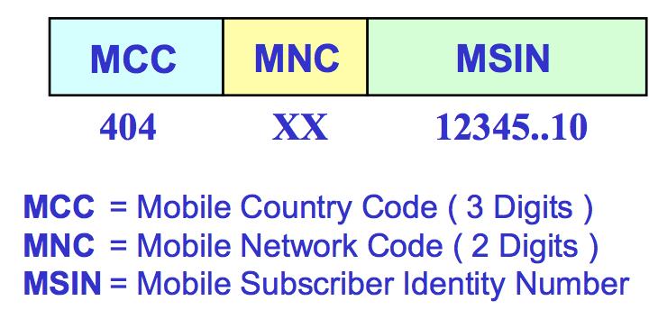
124 8. Location Update MSC should always know the location of the MS so that it can contact it by sending pages whenever required The mobile keeps on informing the MSC about its current location area or whenever it changes from one LA to another This process of informing the MSC is called location update The new LA is updated in VLR LAI = MCC + MNC + LAC MCC = Mobile Country Code 3 digits 1-2 digits Max 16 bits MCC MNC LAC MNC = Mobile Network Code LAC = Location Area Code Identifies a location area within a GSM PLMN network Maximum length of LAC is 16 bits Thus different LAs can be defined in one GSM PLMN
125 Location update types Normal location update IMSI attach Periodic location update Normal location update Mobile powers on and is idle Reads the LAI broadcast on the BCCH Compares with the last stored LAI and if it is different does a location update
126 IMSI attach Saves the network from paging a MS which is not active in the system When MS is turned off or SIM is removed The MS sends a detach signal to the network It is marked as detached When the MS is powered again it reads the current LAI and if it is same does a location update type IMSI attach Attach/detach flag is broadcast on BCCH sys info.
127 Periodic location update Many times the MS enters non-coverage zone The MSC will keep on paging the MS thus wasting precious resources To avoid this the MS has to inform the MSC about its current LAI in a set period of time This time ranges from 0 to 255 decihours [1 decihour = 6 minutes] Periodic location timer value is broadcast on BCCH sys info messages
Global System for Mobile Communications
 Global System for Mobile Communications Contents 1. Introduction 2. Features of GSM 3. Network Components 4. Channel Concept 5. Coding, Interleaving, Ciphering 6. Signaling 7. Handover 8. Location Update
Mohammad Hossein Manshaei 1393
 Mohammad Hossein Manshaei manshaei@gmail.com 1393 GSM 2 GSM Architecture Frequency Band and Channels Frames in GSM Interfaces, Planes, and Layers of GSM Handoff Short Message Service (SMS) 3 subscribers
Chapter 2: Global System for Mobile Communication
 Chapter 2: Global System for Mobile Communication (22 Marks) Introduction- GSM services and features, GSM architecture, GSM channel types, Example of GSM Call: GSM to PSTN call, PSTN to GSM call. GSM frame
Chapter 7 GSM: Pan-European Digital Cellular System. Prof. Jang-Ping Sheu
 Chapter 7 GSM: Pan-European Digital Cellular System Prof. Jang-Ping Sheu Background and Goals GSM (Global System for Mobile Communications) Beginning from 1982 European standard Full roaming in Europe
King Fahd University of Petroleum & Minerals Computer Engineering Dept
 King Fahd University of Petroleum & Minerals Computer Engineering Dept COE 543 Mobile and Wireless Networks Term 022 Dr. Ashraf S. Hasan Mahmoud Rm 22-148-3 Ext. 1724 Email: ashraf@ccse.kfupm.edu.sa 4/14/2003
GSM SYSTEM OVERVIEW. Important Principles and Technologies of GSM
 GSM SYSTEM OVERVIEW Important Principles and Technologies of GSM INTRODUCTION TO GSM WHAT IS GSM? GROUPE SPECIALE MOBILE GLOBAL SYSTEM for MOBILE COMMUNICATIONS OBJECTIVES To be aware of the developments
An overview of the GSM system
 An overview of the GSM system by Javier Gozalvez Sempere An overview of the GSM system Javier Gozálvez Sempere PhD Student in Mobile Communications Communications Division Department of Electronic&Electrical
Communication Systems GSM
 Communication Systems GSM Computer Science Organization I. Data and voice communication in IP networks II. Security issues in networking III. Digital telephony networks and voice over IP 2 last to final
Lecturer: Srwa Mohammad
 Aga private institute for computer science Lecturer: Srwa Mohammad What is GSM? GSM: Global System for Mobile Communications *Evolution of Cellular Networks 1G 2G 2.5G 3G 4G ---------- -----------------------------------------------
Chapter 8: GSM & CDAMA Systems
 Chapter 8: GSM & CDAMA Systems Global System for Mobile Communication (GSM) Second Generation (Digital) Cellular System Operated in 900 MHz band GSM is also operated in 1800 MHz band and this version of
G 364: Mobile and Wireless Networking. CLASS 22, Wed. Mar Stefano Basagni Spring 2004 M-W, 11:40am-1:20pm, 109 Rob
 G 364: Mobile and Wireless Networking CLASS 22, Wed. Mar. 31 2004 Stefano Basagni Spring 2004 M-W, 11:40am-1:20pm, 109 Rob Logical vs. Physical Channels Logical channels (traffic channels, signaling (=control)
GSM Fundamentals. Copyright 2000, Agilent Technologies All Rights Reserved
 GSM Fundamentals Copyright 2000, Agilent Technologies All Rights Reserved System Overview Copyright 2000, Agilent Technologies All Rights Reserved GSM History 1981 Analogue cellular introduced Franco-German
Section A : example questions
 2G1723 GSM Network and Services The exam will consist of two sections: section A (20p) and section B (8p). Section A consist of 20 multiple-choice questions (1p each), where exactly one answer is correct.
G 364: Mobile and Wireless Networking. CLASS 21, Mon. Mar Stefano Basagni Spring 2004 M-W, 11:40am-1:20pm, 109 Rob
 G 364: Mobile and Wireless Networking CLASS 21, Mon. Mar. 29 2004 Stefano Basagni Spring 2004 M-W, 11:40am-1:20pm, 109 Rob Global System for Mobile Communications (GSM) Digital wireless network standard
Wireless CommuniCation. unit 5
 Wireless CommuniCation unit 5 V. ADVANCED TRANSCEIVER SCHEMES Spread Spectrum Systems- Cellular Code Division Multiple Access Systems- Principle, Power control, Effects of multipath propagation on Code
GLOBAL SYSTEM FOR MOBILE COMMUNICATION. ARFCNS, CHANNELS ETI 2511 Thursday, March 30, 2017
 GLOBAL SYSTEM FOR MOBILE COMMUNICATION ARFCNS, CHANNELS ETI 2511 Thursday, March 30, 2017 1 GLOBAL GSM FREQUENCY USAGE 2 EXAMPLE: GSM FREQUENCY ALLOCATION Generally, countries with large land mass would
GSM and Similar Architectures Lesson 08 GSM Traffic and Control Data Channels
 GSM and Similar Architectures Lesson 08 GSM Traffic and Control Data Channels 1 Four Types of Control Data Bursts Access burst The call setup takes place when setting the initial connection using a burst
CS6956: Wireless and Mobile Networks Lecture Notes: 3/23/2015
 CS6956: Wireless and Mobile Networks Lecture Notes: 3/23/2015 GSM Global System for Mobile Communications (reference From GSM to LET by Martin Sauter) There were ~3 billion GSM users in 2010. GSM Voice
An Introduction to Wireless Technologies Part 2. F. Ricci
 An Introduction to Wireless Technologies Part 2 F. Ricci Content Medium access control (MAC): FDMA = Frequency Division Multiple Access TDMA = Time Division Multiple Access CDMA = Code Division Multiple
Modeling and Dimensioning of Mobile Networks: from GSM to LTE. Maciej Stasiak, Mariusz Głąbowski Arkadiusz Wiśniewski, Piotr Zwierzykowski
 Modeling and Dimensioning of Mobile Networks: from GSM to LTE Maciej Stasiak, Mariusz Głąbowski Arkadiusz Wiśniewski, Piotr Zwierzykowski Modeling and Dimensioning of Mobile Networks: from GSM to LTE GSM
MOBILE COMPUTING 4/8/18. Basic Call. Public Switched Telephone Network - PSTN. CSE 40814/60814 Spring Transit. switch. Transit. Transit.
 MOBILE COMPUTING CSE 40814/60814 Spring 2018 Public Switched Telephone Network - PSTN Transit switch Transit switch Long distance network Transit switch Local switch Outgoing call Incoming call Local switch
Global System for Mobile (GSM) Global System for Mobile (GSM) GSM: History. Second Generation Cellular Systems
 Global System for Mobile (GSM) GSM: History. Second Generation Cellular Systems") Global System for Mobile (GSM) David Tipper Associate Professor Graduate Program of Telecommunications and Networking University of Pittsburgh Telcom 2700 Slides 8 Based largely on material from Jochen
Global System for Mobile (GSM) David Tipper Associate Professor Graduate Program of Telecommunications and Networking University of Pittsburgh Telcom 2700 Slides 8 Based largely on material from Jochen
UNIT- 2. Components of a wireless cellular network
 UNIT- 2 Components of a wireless cellular network These network elements may be divided into three groups. MS- Provides the user link to wireless network RBS, BSC The B.S system provides the wireless system
Global System for Mobile (GSM) Global System for Mobile (GSM)
 Global System for Mobile (GSM)") Global System for Mobile (GSM) David Tipper Associate Professor Graduate Program of Telecommunications and Networking University of Pittsburgh Telcom 2700 Slides 8 Based largely on material from Jochen
Global System for Mobile (GSM) David Tipper Associate Professor Graduate Program of Telecommunications and Networking University of Pittsburgh Telcom 2700 Slides 8 Based largely on material from Jochen
GSM NCN-EG-01 Course Outline for GSM
 GSM NCN-EG-01 Course Outline for GSM 1 Course Description: Good understanding of GSM technology and cellular networks is essential for anyone working in GSM or related areas. This course is structured
Global System for Mobile
 Week 15 Global System for Mobile GSM task and intention Services offered by GSM GSM architecture GSM Radio System Channels in GSM Example of GSM call Signal Processing in GSM Page 1 Global System for Mobile
An Introduction to Wireless Technologies Part 2. F. Ricci 2008/2009
 An Introduction to Wireless Technologies Part 2 F. Ricci 2008/2009 Content Multiplexing Medium access control Medium access control (MAC): FDMA = Frequency Division Multiple Access TDMA = Time Division
EUROPEAN ETS TELECOMMUNICATION September 1994 STANDARD
 EUROPEAN ETS 300 573 TELECOMMUNICATION September 1994 STANDARD Source: ETSI TC-SMG Reference: GSM 05.01 ICS: 33.060.30 Key words: European digital cellular telecommunications system, Global System for
Page 1. Problems with 1G Systems. Wireless Wide Area Networks (WWANs) EEC173B/ECS152C, Spring Cellular Wireless Network
 EEC173B/ECS152C, Spring Cellular Wireless Network") EEC173B/ECS152C, Spring 2009 Wireless Wide Area Networks (WWANs) Cellular Wireless Network Architecture and Protocols Applying concepts learned in first two weeks: Frequency planning, channel allocation
EEC173B/ECS152C, Spring 2009 Wireless Wide Area Networks (WWANs) Cellular Wireless Network Architecture and Protocols Applying concepts learned in first two weeks: Frequency planning, channel allocation
Overview of GSM Architecture
 Overview of GSM Architecture GSM/DCS1800 System Some Histories & Some Background GSM/DCS1800 System Architecture High-Level View of Some Scenarios GSM Time Slot Structure GSM Logical Channels GSM Frame
Outline / Wireless Networks and Applications Lecture 18: Cellular: 1G, 2G, and 3G. Advanced Mobile Phone Service (AMPS)
") Outline 18-452/18-750 Wireless Networks and Applications Lecture 18: Cellular: 1G, 2G, and 3G 1G: AMPS 2G: GSM 2.5G: EDGE, CDMA 3G: WCDMA Peter Steenkiste Spring Semester 2017 http://www.cs.cmu.edu/~prs/wirelesss17
Outline 18-452/18-750 Wireless Networks and Applications Lecture 18: Cellular: 1G, 2G, and 3G 1G: AMPS 2G: GSM 2.5G: EDGE, CDMA 3G: WCDMA Peter Steenkiste Spring Semester 2017 http://www.cs.cmu.edu/~prs/wirelesss17
Mobile Network Evolution Part 1. GSM and UMTS
 Mobile Network Evolution Part 1 GSM and UMTS GSM Cell layout Architecture Call setup Mobility management Security GPRS Architecture Protocols QoS EDGE UMTS Architecture Integrated Communication Systems
Developing Mobile Applications
 Developing Mobile Applications GSM networks 1 carriers GSM 900 MHz 890-915 MHz 935-960 MHz up down 200 KHz 200 KHz 25 MHz 25 MHz 2 frequency reuse A D K B J L C H E G I F A 3 Reuse patterns 4/12 4 base
TELE4652 Mobile and Satellite Communications
 Mobile and Satellite Communications Lecture 1 Introduction to Cellular Mobile Communications Public Switched Telephone Networks (PSTN) Public Land Mobile Networks (PLMN) evolved from the PSTN - Aimed to
Wireless Telephony in Germany. Standardization of Networks. GSM Basis of Current Mobile Systems
 Wireless Telephony in Germany Chapter 2 Technical Basics: Layer Methods for Medium Access: Layer 2 Chapter 3 Wireless Networks: Bluetooth, WLAN, WirelessMAN, WirelessWAN Mobile Telecommunication Networks:
RADIO LINK ASPECT OF GSM
 RADIO LINK ASPECT OF GSM The GSM spectral allocation is 25 MHz for base transmission (935 960 MHz) and 25 MHz for mobile transmission With each 200 KHz bandwidth, total number of channel provided is 125
GSM GSM TECHNICAL April 1998 SPECIFICATION Version 5.4.0
 GSM GSM 05.01 TECHNICAL April 1998 SPECIFICATION Version 5.4.0 Source: SMG Reference: RGTS/SMG-020501QR3 ICS: 33.020 Key words: Digital cellular telecommunications system, Global System for Mobile communications
3GPP TS V8.0.1 ( )
") TS 08.52 V8.0.1 (2002-05) Technical Specification 3rd Generation Partnership Project; Technical Specification Group GSM EDGE Radio Access Network; Base Station Controller - Base Transceiver Station (BSC
TS 08.52 V8.0.1 (2002-05) Technical Specification 3rd Generation Partnership Project; Technical Specification Group GSM EDGE Radio Access Network; Base Station Controller - Base Transceiver Station (BSC
Chapter 9 GSM. Distributed Computing Group. Mobile Computing Summer 2003
 Chapter 9 GSM Distributed Computing Group Mobile Computing Summer 2003 Overview GSM Overview Services Architecture Cell management TDMA, FDMA Orientation Handover Authentications HSCSD, GPRS Distributed
2G Mobile Communication Systems
 2G Mobile Communication Systems 2G Review: GSM Services Architecture Protocols Call setup Mobility management Security HSCSD GPRS EDGE References Jochen Schiller: Mobile Communications (German and English),
Other signalling CRs, GSM Phase 2/2+
 ETSI TC SMG TDoc SMG 331 /97 Meeting #22 Kristiansand, 9th - 13th June 1997 Source : SMG7 Other signalling CRs, GSM 11.10-1 Phase 2/2+ Introduction : This document contains CRs to GSM 11.10-1 for phase
Wireless Telecommunication Systems GSM as basis of current systems Enhancements for data communication: HSCSD, GPRS, EDGE UMTS: Future or not?
 Chapter 2 Technical Basics: Layer 1 Methods for Medium Access: Layer 2 Chapter 3 Wireless Networks: Bluetooth, WLAN, WirelessMAN, WirelessWAN Mobile Networks: GSM, GPRS, UMTS Chapter 4 Mobility on the
10EC81-Wireless Communication UNIT-6
 UNIT-6 The first form of CDMA to be implemented is IS-95, specified a dual mode of operation in the 800Mhz cellular band for both AMPS and CDMA. IS-95 standard describes the structure of wideband 1.25Mhz
Politecnico di Milano Facoltà di Ingegneria dell Informazione. MRN 6 GSM part 2. Mobile Radio Networks Prof. Antonio Capone
 Politecnico di Milano Facoltà di Ingegneria dell Informazione MRN 6 GSM part 2 Mobile Radio Networks Prof. Antonio Capone Signaling A. Capone: Mobile Radio Network 2 Telephone signaling o In classic telephone
Access Methods in GSM
 TDMA Methods, page 1 Access Methods in GSM 1. Fundamentals of Multiple Access Frequency division multiple access FDMA Time division multiple access TDMA Code division multiple access CDMA 2. TDMA in GSM
3GPP TS V ( )
") TS 05.02 V4.11.0 (2001-08) Technical Specification 3rd Generation Partnership Project; Technical Specification Group GSM/EDGE Radio Access Network; Multiplexing and multiple access on the radio path (Phase
TS 05.02 V4.11.0 (2001-08) Technical Specification 3rd Generation Partnership Project; Technical Specification Group GSM/EDGE Radio Access Network; Multiplexing and multiple access on the radio path (Phase
Chapter 5. North American Cellular System Based on Time Division Multiple Access
 Chapter 5. North American Cellular System Based on Time Division Multiple Access Background and Goals AMPS can not support user transparency roaming Interim Standard 41 (IS 41) is to deliver AMPS services
RECOMMENDATION ITU-R M DIGITAL CELLULAR LAND MOBILE TELECOMMUNICATION SYSTEMS. (Question ITU-R 107/8)
") Rec. ITU-R M.1073-1 1 RECOMMENDATION ITU-R M.1073-1 DIGITAL CELLULAR LAND MOBILE TELECOMMUNICATION SYSTEMS (Question ITU-R 107/8) (1994-1997) Rec. ITU-R M.1073-1 Summary This Recommendation recommends
Rec. ITU-R M.1073-1 1 RECOMMENDATION ITU-R M.1073-1 DIGITAL CELLULAR LAND MOBILE TELECOMMUNICATION SYSTEMS (Question ITU-R 107/8) (1994-1997) Rec. ITU-R M.1073-1 Summary This Recommendation recommends
Intersystem Operation and Mobility Management. First Generation Systems
 Intersystem Operation and Mobility Management David Tipper Associate Professor Graduate Program in Telecommunications and Networking University of Pittsburgh Telcom 2700 Slides 6 http://www.tele.pitt.edu/tipper.html
TS V6.1.1 ( )
") Technical Specification Digital cellular telecommunications system (Phase 2+); Physical layer on the radio path; General description (GSM 05.01 version 6.1.1 Release 1997) GLOBAL SYSTEM FOR MOBILE COMMUNICATIONS
Technical Specification Digital cellular telecommunications system (Phase 2+); Physical layer on the radio path; General description (GSM 05.01 version 6.1.1 Release 1997) GLOBAL SYSTEM FOR MOBILE COMMUNICATIONS
Department of Computer Science & Technology 2014
 Unit 1. Wireless Telecommunication Systems and Networks Short Questions 1. What is Electromagnetic spectrum? 2 State the purpose of Induction. 3. What is the range of Radio Frequency? 4. What are two parameters
Cellular Network. Ir. Muhamad Asvial, MSc., PhD
 Cellular Network Ir. Muhamad Asvial, MSc., PhD Center for Information and Communication Engineering Research (CICER) Electrical Engineering Department - University of Indonesia E-mail: asvial@ee.ui.ac.id
GSM and WCDMA RADIO SYSTEMS ETIN15. Lecture no: Ove Edfors, Department of Electrical and Information Technology
 RADIO SYSTEMS ETIN15 Lecture no: 11 GSM and WCDMA Ove Edfors, Department of Electrical and Information Technology Ove.Edfors@eit.lth.se 2015-05-12 Ove Edfors - ETIN15 1 Contents (Brief) history of mobile
GSM. 84 Theoretical and general applications
 GSM GSM, GPRS, UMTS what do all of these expressions mean and what possibilities are there for data communication? Technical descriptions often contain abbreviations and acronyms. We have chosen to use
Unit V. Multi-User Radio Communication
 Unit V Multi-User Radio Communication ADVANCED MOBILE PONE SERVICE (AMPS) 1906: 1 st radio transmission of Human voice. What s the medium? Used an RC circuit to modulate a carrier frequency that radiated
)454 1 '%.%2!,!30%#43 /& 05",)#,!.$ -/"),%.%47/2+3 05",)#,!.$ -/"),%.%47/2+3. )454 Recommendation 1 INTERNATIONAL TELECOMMUNICATION UNION
454 1 '%.%2!,!30%#43 /& 05,)#,!.$ -/),%.%47/2+3 05,)#,!.$ -/),%.%47/2+3. )454 Recommendation 1 INTERNATIONAL TELECOMMUNICATION UNION") INTERNATIONAL TELECOMMUNICATION UNION )454 1 TELECOMMUNICATION STANDARDIZATION SECTOR OF ITU 05",)#,!.$ -/"),%.%47/2+3 '%.%2!,!30%#43 /& 05",)#,!.$ -/"),%.%47/2+3 )454 Recommendation 1 (Extract from the
INTERNATIONAL TELECOMMUNICATION UNION )454 1 TELECOMMUNICATION STANDARDIZATION SECTOR OF ITU 05",)#,!.$ -/"),%.%47/2+3 '%.%2!,!30%#43 /& 05",)#,!.$ -/"),%.%47/2+3 )454 Recommendation 1 (Extract from the
Chapter 5 Acknowledgment:
 Chapter 5 Acknowledgment: This material is based on the slides formatted by Dr Sunilkumar S. Manvi and Dr Mahabaleshwar S. Kakkasageri, the authors of the textbook: Wireless and Mobile Networks, concepts
Introduction to IS-95 CDMA p. 1 What is CDMA p. 1 History of CDMA p. 2 Forms of CDMA p MHz CDMA p MHz CDMA (PCS) p. 6 CDMA Parts p.
 p. 6 CDMA Parts p.") Introduction to IS-95 CDMA p. 1 What is CDMA p. 1 History of CDMA p. 2 Forms of CDMA p. 3 800 MHz CDMA p. 6 1900 MHz CDMA (PCS) p. 6 CDMA Parts p. 7 Mobile Station p. 8 Base Station Subsystem (BSS) p.
Introduction to IS-95 CDMA p. 1 What is CDMA p. 1 History of CDMA p. 2 Forms of CDMA p. 3 800 MHz CDMA p. 6 1900 MHz CDMA (PCS) p. 6 CDMA Parts p. 7 Mobile Station p. 8 Base Station Subsystem (BSS) p.
3GPP TS V5.6.0 ( )
") 3GPP TS 05.03 V5.6.0 (2000-09) Technical Specification 3rd Generation Partnership Project; Technical Specification Group GERAN; Digital cellular telecommunications system (Phase 2+); Channel coding (Release
3GPP TS 05.03 V5.6.0 (2000-09) Technical Specification 3rd Generation Partnership Project; Technical Specification Group GERAN; Digital cellular telecommunications system (Phase 2+); Channel coding (Release
Mobile Communications II From Cellular to Mobile Services
 Mobile Communications II From Cellular to Mobile Services Prof. Dr.-Ing. Rolf Kraemer chair owner telefon: 0335 5625 342 fax: 0335 5625 671 e-mail: kraemer [ at ] ihp-microelectronics.com web: General
CS 218 Fall 2003 October 23, 2003
 CS 218 Fall 2003 October 23, 2003 Cellular Wireless Networks AMPS (Analog) D-AMPS (TDMA) GSM CDMA Reference: Tanenbaum Chpt 2 (pg 153-169) Cellular Wireless Network Evolution First Generation: Analog AMPS:
MODEL ANSWER SUMMER 17 EXAMINATION 17657
 MODEL ANSWER SUMMER 17 EXAMINATION 17657 Subject Title: Mobile Communication Subject Code: Important Instructions to examiners: 1) The answers should be examined by key words and not as word-to-word as
GSM and Similar Architectures Lesson 04 GSM Base station system and Base Station Controller
 GSM and Similar Architectures Lesson 04 GSM Base station system and Base Station Controller 1 GSM network architecture Radio subsystem (RSS) Network subsystem (NSS) Operation subsystem (OSS) 2 RSS Consists
a) Describe the basic cellular system. (2M Diagram & 2 M Explanation)
 Describe the basic cellular system. (2M Diagram & 2 M Explanation)") Important Instructions to examiners: 1. The answers should be examined by key words and not as word-to-word as given in the model answer scheme. 2. The model answer and the answer written by candidate
Important Instructions to examiners: 1. The answers should be examined by key words and not as word-to-word as given in the model answer scheme. 2. The model answer and the answer written by candidate
GSM GSM TELECOMMUNICATION May 1996 STANDARD Version 5.0.0
 GSM GSM 04.13 TELECOMMUNICATION May 1996 STANDARD Version 5.0.0 Source: ETSI TC-SMG Reference: TS/SMG-030413Q ICS: 33.060.50 Key words: Digital cellular telecommunications system, Global System for Mobile
Overview of GSM: The Global System for Mobile Communications. John Scourias. University of Waterloo.
 Overview of GSM: The Global System for Mobile Communications John Scourias University of Waterloo jscourias@neumann.uwaterloo.ca March 13, 1996 1 History of GSM During the early 1980s, analog cellular
First Generation Systems
 Intersystem Operation and Mobility Management David Tipper Associate Professor Graduate Program in Telecommunications and Networking University of Pittsburgh Telcom 2720 Slides 6 http://www.tele.pitt.edu/tipper.html
Page 1. What is a Survey? : Wireless Networks Lecture 8: Cellular Networks. Deliverables. Surveys. Cell splitting.
 What is a Survey? 18-759: Wireless Networks Lecture 8: Cellular Networks Dina Papagiannaki & Peter Steenkiste Departments of Computer Science and Electrical and Computer Engineering Spring Semester 2009
RADIO SYSTEMS ETIN15. Lecture no: GSM and WCDMA. Ove Edfors, Department of Electrical and Information Technology
 RADIO SYSTEMS ETIN15 Lecture no: 11 GSM and WCDMA Ove Edfors, Department of Electrical and Information Technology Ove.Edfors@eit.lth.se 1 Contents (Brief) history of mobile telephony Global System for
Part 5. 2G and 2.5G Mobile Communication Systems
 Part 5. 2G and 2.5G Mobile Communication Systems p. 1 GSM (Global System for Mobile Communications) p. 2 Global GSM Subscribers 3000 Number of GSM Subscribers (Million) 2500 2000 1500 1000 500 0 1 50 100
GSM Interceptor Fast and reliable interception of GSM traffic
 GSM Interceptor Fast and reliable interception of GSM traffic Maximum accuracy, sensitivity and flexibility Total indefectibility Support for all frequency bands User-friendly operation Wide range of antennas
APPLICATION PROGRAMMING: MOBILE COMPUTING [ INEA00112W ] Marek Piasecki PhD Wireless Telecommunication
![APPLICATION PROGRAMMING: MOBILE COMPUTING [ INEA00112W ] Marek Piasecki PhD Wireless Telecommunication](/thumbs/82/86735605.jpg "APPLICATION PROGRAMMING: MOBILE COMPUTING [ INEA00112W ] Marek Piasecki PhD Wireless Telecommunication") APPLICATION PROGRAMMING: MOBILE COMPUTING [ INEA00112W ] Marek Piasecki PhD Wireless Telecommunication (W6/2013) What is Wireless Communication? Transmitting/receiving voice and data using electromagnetic
APPLICATION PROGRAMMING: MOBILE COMPUTING [ INEA00112W ] Marek Piasecki PhD Wireless Telecommunication (W6/2013) What is Wireless Communication? Transmitting/receiving voice and data using electromagnetic
3GPP TS V ( )
") 1 3GPP TS 05.08 V5.10.0 (2000-09) Technical Specification 3rd Generation Partnership Project; Technical Specification Group GERAN; Digital cellular telecommunications system (Phase 2+); Radio subsystem
1 3GPP TS 05.08 V5.10.0 (2000-09) Technical Specification 3rd Generation Partnership Project; Technical Specification Group GERAN; Digital cellular telecommunications system (Phase 2+); Radio subsystem
Data and Computer Communications. Chapter 10 Cellular Wireless Networks
 Data and Computer Communications Chapter 10 Cellular Wireless Networks Cellular Wireless Networks 5 PSTN Switch Mobile Telecomm Switching Office (MTSO) 3 4 2 1 Base Station 0 2016-08-30 2 Cellular Wireless
Transcoding free voice transmission in GSM and UMTS networks
 Transcoding free voice transmission in GSM and UMTS networks Sara Stančin, Grega Jakus, Sašo Tomažič University of Ljubljana, Faculty of Electrical Engineering Abstract - Transcoding refers to the conversion
ETSI TS V7.0.1 ( )
") TS 100 573 V7.0.1 (1999-07) Technical Specification Digital cellular telecommunications system (Phase 2+); Physical layer on the radio path; General description (GSM 05.01 version 7.0.1 Release 1998) GLOBAL
TS 100 573 V7.0.1 (1999-07) Technical Specification Digital cellular telecommunications system (Phase 2+); Physical layer on the radio path; General description (GSM 05.01 version 7.0.1 Release 1998) GLOBAL
Wireless and mobile communication
 Wireless and mobile communication Wireless communication Multiple Access FDMA TDMA CDMA SDMA Mobile Communication GSM GPRS GPS Bluetooth Content What is wireless communication? In layman language it is
CHAPTER 2 WCDMA NETWORK
 CHAPTER 2 WCDMA NETWORK 2.1 INTRODUCTION WCDMA is a third generation mobile communication system that uses CDMA technology over a wide frequency band to provide high-speed multimedia and efficient voice
SUMMER 13 EXAMINATION
 MAHARASHTRA STATE BOARD OF TECHNICAL EDUCATION (Autonomous) (ISO/IEC - 27001-2005 Certified) Subject Code: 12272 SUMMER 13 EXAMINATION Model Answer Important Instructions to examiners: 1) The answers should
3.6. Cell-Site Equipment. Traffic and Cell Splitting Microcells, Picocelles and Repeaters
 3.6. Cell-Site Equipment Traffic and Cell Splitting Microcells, Picocelles and Repeaters The radio transmitting equipment at the cell site operates at considerably higher power than do the mobile phones,
MAHARASHTRA STATE BOARD OF TECHNICAL EDUCATION (Autonomous) (ISO/IEC Certified)
 (ISO/IEC Certified)") WINTER 16 EXAMINATION Model Answer Subject Code: 17657 Important Instructions to examiners: 1) The answers should be examined by key words and not as word-to-word as given in the model answer scheme. 2)
WINTER 16 EXAMINATION Model Answer Subject Code: 17657 Important Instructions to examiners: 1) The answers should be examined by key words and not as word-to-word as given in the model answer scheme. 2)
INTELLIGENCE MOBILE LOCATOR. World Leader in Supplying INTELLIGENCE Equipment and Training TA08002
 MOBILE LOCATOR TA08002 Coverage of Uall fouru frequency bands (850, 900, 1800, 1900) 4 wide-band receivers and 64 digital processing receivers Real-time handling of A5/1 and A5/2 encryption types Monitoring
Personal Communication System
 Personal Communication System Differences Between Cellular Systems and PCS IS-136 (TDMA) PCS GSM i-mode mobile communication IS-95 CDMA PCS Comparison of Modulation Schemes Data Communication with PCS
CHAPTER 2. Instructor: Mr. Abhijit Parmar Course: Mobile Computing and Wireless Communication ( )
") CHAPTER 2 Instructor: Mr. Abhijit Parmar Course: Mobile Computing and Wireless Communication (2170710) Syllabus Chapter-2.1 Cellular Wireless Networks 2.1.1 Principles of Cellular Networks Underlying technology
CHAPTER 2 Instructor: Mr. Abhijit Parmar Course: Mobile Computing and Wireless Communication (2170710) Syllabus Chapter-2.1 Cellular Wireless Networks 2.1.1 Principles of Cellular Networks Underlying technology
GSM GSM TECHNICAL May 1996 SPECIFICATION Version 5.1.0
 GSM GSM 05.03 TECHNICAL May 1996 SPECIFICATION Version 5.1.0 Source: ETSI TC-SMG Reference: TS/SMG-020503QR ICS: 33.060.50 Key words: Digital cellular telecommunications system, Global System for Mobile
GTBIT ECE Department Wireless Communication
 Q-1 What is Simulcast Paging system? Ans-1 A Simulcast Paging system refers to a system where coverage is continuous over a geographic area serviced by more than one paging transmitter. In this type of
GSM GSM TECHNICAL August 1997 SPECIFICATION Version 5.2.0
 GSM GSM 04.03 TECHNICAL August 1997 SPECIFICATION Version 5.2.0 Source: ETSI SMG Reference: TS/SMG-030403QR1 ICS: 33.020 Key words: Digital cellular telecommunications system, Global System for Mobile
Cellular Wireless Networks. Chapter 10
 Cellular Wireless Networks Chapter 10 Cellular Network Organization Use multiple low-power transmitters (100 W or less) Areas divided into cells Each cell is served by base station consisting of transmitter,
EUROPEAN ETS TELECOMMUNICATION August 1996 STANDARD
 EUROPEAN ETS 300 578 TELECOMMUNICATION August 1996 STANDARD Sixth Edition Source: ETSI TC-SMG Reference: RE/SMG-020508PR5 ICS: 33.060.50 Key words: Digital telecommunications system, Global System for
Wireless WANS and MANS. Chapter 3
 Wireless WANS and MANS Chapter 3 Cellular Network Concept Use multiple low-power transmitters (100 W or less) Areas divided into cells Each served by its own antenna Served by base station consisting of
a) Describe the basic cellular system. (2M Diagram & 2 M Explanation)
 Describe the basic cellular system. (2M Diagram & 2 M Explanation)") Important Instructions to examiners: 1. The answers should be examined by key words and not as word-to-word as given in the model answer scheme. 2. The model answer and the answer written by candidate
Important Instructions to examiners: 1. The answers should be examined by key words and not as word-to-word as given in the model answer scheme. 2. The model answer and the answer written by candidate
Introduction to GSM. Introduction to GSM, page Development of GSM. History of GSM. Market situation. GSM s future development
 Introduction to GSM, page 1 Introduction to GSM 1. Development of GSM History of GSM Market situation GSM s future development Services offered by GSM GSM specifications 2. OSI reference model 3. RF interface
Mobile Radio Communications
 Session 8: Mobile networks Session 8, page 1 Mobile (cellular) networks MSC PSTN PLMN BSC Session 8, page 2 Cellular systems around the world US systems (public cellular, cell phone systems) AMPS: Advance
ETSI TS V ( )
") TS 144 003 V11.0.0 (2012-10) Technical Specification Digital cellular telecommunications system (Phase 2+); Mobile Station - Base Station System (MS - BSS) Interface Channel Structures and Access Capabilities
TS 144 003 V11.0.0 (2012-10) Technical Specification Digital cellular telecommunications system (Phase 2+); Mobile Station - Base Station System (MS - BSS) Interface Channel Structures and Access Capabilities
ECE 476/ECE 501C/CS Wireless Communication Systems Winter Lecture 9: Multiple Access, GSM, and IS-95
 ECE 476/ECE 501C/CS 513 - Wireless Communication Systems Winter 2003 Lecture 9: Multiple Access, GSM, and IS-95 Outline: Two other important issues related to multiple access space division with smart
F/TDMA Cellular Access and GSM
 F/TDMA Cellular Access and GSM Marceau Coupechoux 6 Feb. 2019 MC Cellular access 6 Feb. 2019 1 / 32 Outlines Cellular access principles Channel reuse 1 Call blocking GSM channels 1. Figures pp. 8, 9, 10,
3GPP TS V ( )
") TS 04.18 V8.27.0 (2006-05) Technical Specification 3rd Generation Partnership Project; Technical Specification Group GSM/EDGE Radio Access Network; Mobile radio interface layer 3 specification; Radio Resource
TS 04.18 V8.27.0 (2006-05) Technical Specification 3rd Generation Partnership Project; Technical Specification Group GSM/EDGE Radio Access Network; Mobile radio interface layer 3 specification; Radio Resource
GPRS Air Interface aspects
 General Packet Radio Services (Placeholder for a cover picture; this picture should always cover the whole slide width as shown here) 21MAT MAR 09.09.02 Re 08/00 Air Interface aspects 1 1 General Packet
ETSI TS V8.0.2 ( )
") TS 100 552 V8.0.2 (2002-05) Technical Specification Digital cellular telecommunications system (Phase 2+); Mobile Station - Base Station System (MS - BSS) Interface Channel Structures and Access Capabilities
TS 100 552 V8.0.2 (2002-05) Technical Specification Digital cellular telecommunications system (Phase 2+); Mobile Station - Base Station System (MS - BSS) Interface Channel Structures and Access Capabilities
Chapter 11 Existing Wireless Systems
 Chapter 11 Existing Wireless Systems Copyright 2011, Dr. Dharma P. Agrawal and Dr. Qing-An Zeng. All rights reserved. 1 AMPS Outline Characteristics of AMPS Operation of AMPS General working of AMPS phone