The design of the linear PSU of the computer within the limits of the project cmp2.
|
|
|
- Austin Anthony
- 6 years ago
- Views:
Transcription

 module.")

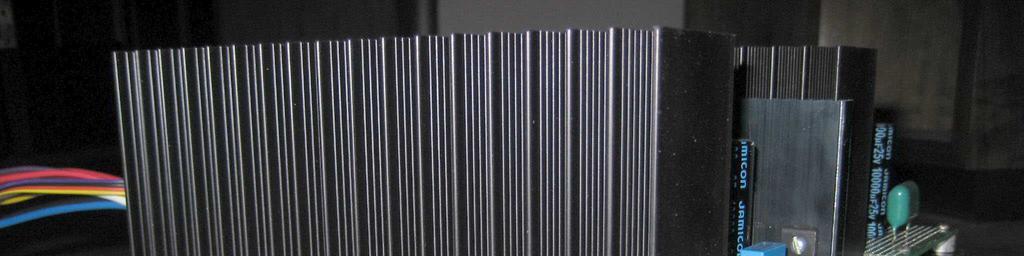
1 The design of the linear PSU of the computer within the limits of the project cmp2. The primary goal at replacement of a computer power supply unit by linear one was elimination of impulse hindrances of the power supply unit and minimization of interferences of separate chains of the computer against each other. In particular it is very important to allocate a power supply unit for a sound card in the particular (first) module, i.e. supply it not only from the particular regulator, but also from the particular transformer. Also it is considered that the CPU is a source of strong impulse noise. We also allocate its power supply unit in the particular (second) module. The third module is most loaded, provides a supply for socket P24 of a system board. And the fourth module is the service module. The power supply sockets of the hard disk, the monitor which has been built in the case of the computer, usb devices etc are connected to it. The quantity of supply voltages in this module (and output currents) are defined by a concrete configuration of the computer (type of the used equipment, power consumption). Fig.1 1

2 Fig.2 2

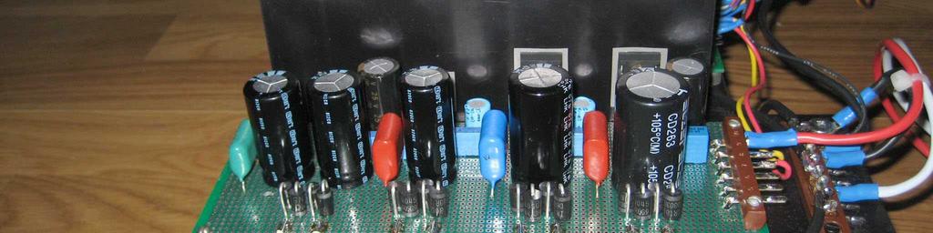
3 3 Fig.3
 and provides the stabilized voltage + 5 V (see Appendix 2).")

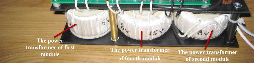
4 Fig.4 First module. It is on the circuit board (position 12 in the fig. 1). The first module is defined for a supply of a digital part of sound card Esi@Juli (the analogue part is not used) and provides the stabilized voltage + 5 V (see Appendix 2). The digital part of sound card Esi@Juli consumes the maximum current 170 ma (in a play mode). The first module should provide not less double current consumption. The maximum output current of this module is 2 A. The power transformer is toroidal 60 VA; the voltage of a secondary winding in an idling mode is 6-8 V. The Schottky rectifiers with maximum average forward rectified current 3-5 A (SR350, SR360, 1N5822, SR560). The total filtering capacitors capacity of the rectifier is µf. The regulator is LM1084 IT-5.0 (position 4 in the fig. 1). The output capacitor is high-quality Elna Cerafine 1000 µf 25V. Second module. It is on the circuit board (position 12 in the fig. 1). The second module is defined for a supply of the socket P4 (+12 V power supply of the CPU). 4
5 The current consumption of the CPU Intel E7400 in the given cmp2 s configuration (the core voltage is no more than 0.9 V, the core speed is GHz) is no more than 0.5 A. The maximum output current of this module is 2 A. The power transformer is toroidal 75 VA; the voltage of a secondary winding in an idling mode is V. The Schottky rectifiers with maximum average forward rectified current 3-5 A (SR350, SR360, 1N5822, SR560). The filtering capacitor capacity of the rectifier is µf. The regulator is LT1083CP (a position 7 in the fig. 1). The output capacitor is high-quality Elna Cerafine 1000 µf 25V. The adjustment terminal of the LT1083CP is bypassed by the high-grade capacitors Elna Silmic II 10 µf 35 V (C5 in the fig.6). It is made in all modules in which the LT1083CP is used. Third module. It is on the circuit boards (position 13 in the fig. 1 and position 10 in the fig. 2). The third module supplies the system board s socket P24. The voltages are the following: V, + 5 V, + 12 V and 12 V. It seems the voltage + 5 V is most significant. The real current consumption on the bus +5 V does not exceed 3.5 A. The maximum output current of the third module is 5 A (bus +5 V). The Schottky rectifiers with maximum average forward rectified current 15 A (12TQ045) are installed on the separate heatsink (a position 11 in the fig. 4). The total filtering capacitors capacity of the rectifier is µf. The circuit design of double consecutive stabilization is applied because of the high significance of a supply + 5 V. The first regulator outputs the voltage V, and the second regulator outputs the voltage + 5 V. Both regulators are LT1083CP (positions 1 and 2 in the fig. 1). The output capacitor is high-quality Elna Cerafine 1000 µf 25V. The circuit design of a 1.5-second delay of supplying voltage to the pin Power Ok (+ 5 V connector P24) and the circuit design of switching-off of the built-in monitor (a position 3 in the fig.1) is had. The usage of the linear power module has shown that the voltage +5 V can be supplied to the contact Power Ok simultaneously with other voltages, and switching-off of the built-in monitor does not influence quality of a playback s sound. So these two options it is possible to expel. But if all the same there are problems with system board's startup it is recommended to use a delay circuit. 5
6 The delay circuit The monitor off/on circuit The real current consumption on the bus +3.3 V does not exceed 0.3 A. The maximum output current of the third module is 2 A (bus +3.3 V). The Schottky rectifiers with maximum average forward rectified current 3-5 A (SR350, SR360, 1N5822, SR560). The total filtering capacitors capacity of the rectifier is µf. The regulator is LM1085IT-3.3. It is on the circuit boards (position 10 in the fig.2). The output capacitor is high-quality Elna Cerafine 1000 µf 25V. 6
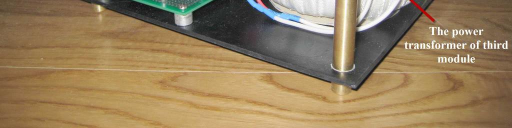
7 The real current consumption on the bus +12 V does not exceed 0.15A. The maximum output current of the third module is 3 A (bus +12 V). The Schottky rectifiers with maximum average forward rectified current 5 A (SR560). The filtering capacitor capacity of the rectifier is µf. The regulator is LM1085IT-12. It is on the circuit boards (position 10 in the fig.2). The output capacitor is high-quality Elna Cerafine 1000 µf 25V. The real current consumption on the bus - 12 V is not known. This voltage is used only at computer start. The maximum output current of the third module is 1 A (bus -12 V). The Schottky rectifiers with maximum average forward rectified current 3-5 A (SR350, SR360, 1N5822, SR560). The filtering capacitor capacity of the rectifier is µf. The regulator is LM7912. It is on the circuit boards (position 10 in the fig.2). The output capacitor is high-quality Elna Cerafine 1000 µf 25V. The power transformer of the third module is toroidal 100 VA. It has four secondary windings. The voltages of secondary windings in an idling mode are 5-6 V (for +3.3 V), 6-8 V (for +5 V), V (for +12 V) and V (for -12 V). Fourth module. It is on the circuit board (position 12 in the fig. 1). The fourth (service) module provides the stabilized voltage + 5 V and + 12 V. The real current consumption on these voltage can be various in different configurations, therefore we specify the maximum values for the given configuration cmp2 (with one HDD 1000 Western Digital Caviar Green): on the bus +5V 3A, on the bus +12V 2A. The Schottky rectifiers with maximum average forward rectified current 5-8 A (SR560, 80SQ045). The filtering capacitors capacity of the rectifiers are µf. The regulator +5V is LM1084 IT 5.0 (position 5 in the fig. 1). The regulator +12V is LT1083CP (position 6 in the fig. 1). The output capacitors are 470 µf. The power transformer of the fourth module is toroidal 75 VA. It has two secondary windings. The voltages of secondary windings in an idling mode are 6-8 V (for +5 V) and V (for +12 V). The terminal block (position 9 in the fig.1) is the center of the PSU s «ground star». The ground buses from all three circuit boards (are soldered by a thick wire to filtering capacitors of rectifiers see the position 8 in the fig.1) converge here and diverge to the power consumers. 7
8 Appendix 1 We give the standard schematic of the stabilized power supply unit which it was used for each voltage in the described power supply unit. Fig.5 Fig.6 8
9 The explanatory notes to schematics: 1. TV1 the power toroidal transformer 2. VD the Schottky rectifiers 3. C1 and C2 the filtering capacitors, C3 and C4 output capacitors 4. 2 and 4 - the qualitative film capacitors with small capacity shunting electrolytic capacitors (the film capacitor capacity is around 1/100 part of the electrolytic capacitor capacity). 2 and 4 are possible not to install in case of use of electrolytic capacitors Black Gate, Elna Cerafine, Elna Silmic, Panasonic FC and similar. 5. R1 the load resistor providing the minimum load current (5-10 ma) in the psu s output. 6. U1 the regulator: the regulator providing fixed value of stabilized voltage in output of the unit without the additional resistors is represented in the fig.5 and with the additional resistors R2 and R3 is represented in the fig.6. The benefit of the circuit design in the fig.6 is in the additional capacitor C5 providing additional ripple rejection. R2, R3, C5 are chosen according to the regulator's datasheets. 9


10 Appendix 2. The external power supply for a digital part of sound card Esi@Juli. The digital part of sound card Esi@Juli gets a feed from a system board through PCI socket only on the power bus + 5 V. Fig.7 10
")

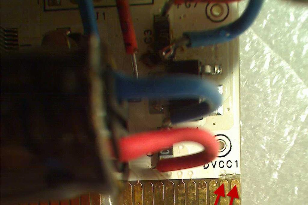
11 The matching printed conductors on the Juli s board (only 8 conductors) is necessary to cut carefully, as is shown in the fig. 8,9,10,11. Fig.8 11
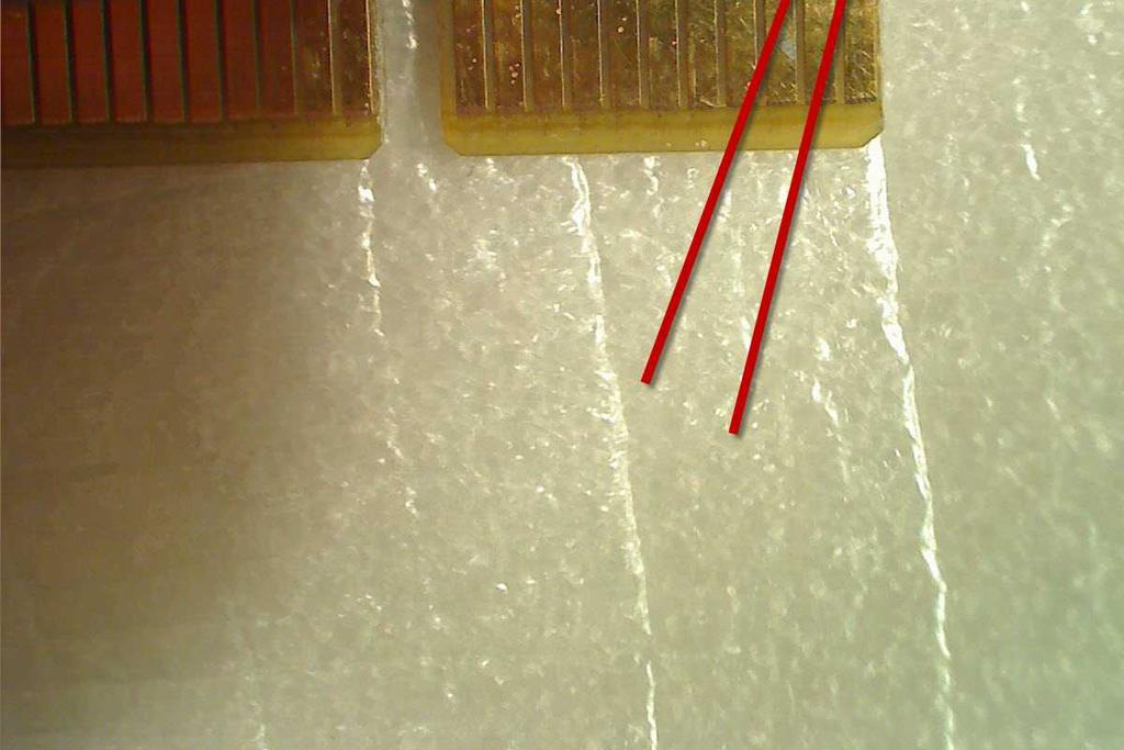
12 Fig.9 12
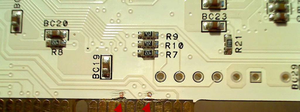

13 Fig.10 13
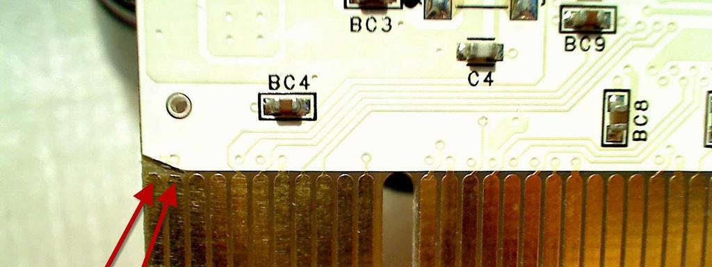

14 Fig.11 14

 of the sound")
. Fig.12 Fig.")
15 It is convenient to input external voltage + 5 V to the pins 2 (+ 5 V) and 4 ("ground") of the sound card s connector J1 (fig. 12 and 13). Fig.12 Fig.13 15


16 The chip U1 of the voltage regulator V for a power supply of the chip Tremor is visible in the fig. 12. The capacitors C1 and 3 are the input capacitors, 2 is the output capacitor. These capacitors it is recommended bypass by high-grade electrolytic capacitors Elna Cerafine or Elna Silmic µf. Fig.14 16


17 It is recommended to install connector BNC (spdif out) on the Juli s backplane, which leading-outs to solder by short conductors directly to leading-outs of the secondary winding of pulse transformer T2, as is shown in the fig.15 (the case of connector BNC should be isolated from the backplane). Fig.15 17
18 Appendix 3. The pinout of the connector P24. Fig.16 Fig.17 18
19 Fig.18 Connector P24: pins 1,2,12,13: +3.3 V; pins 4,6,8,9,21,22,23: +5 V; pin 10,11: +12 V; pin 14: -12V; pins 3,5,7,15,17,18,19,24: ground, pins 16,20: no connection. 19
5V/550mA Battery Charger Solution Using AP3703
 System Engineering Department BCD Semiconductor Manufacturing Limited 01/19/2009 Summary of Report Specifications 85~264Vac, 5V/550mA Applications Key features Cellphone charger or adapter Primary Side
FAN A Adjustable/Fixed Ultra Low Dropout Linear Regulator. Description. Features. Applications. Typical Applications.
 www.fairchildsemi.com 5A Adjustable/Fixed Ultra Low Dropout Linear Regulator Features Ultra Low dropout voltage,.4v typical at 5A 1.2V Versions available for GTL termination Remote sense operation Fast
PI3HDMI1210(-A) PI3HDMI1210-A Demo Board Rev.A User Manual
 PI3HDMI1210-A Demo Board Rev.A User Manual") PI3HDMI1210(-A) PI3HDMI1210-A Demo Board Rev.A User Manual Introduction This user manual describes the components and the usage of PI3HDMI1210(-A) demo Board Rev.A. Figure 1: Top View of PI3HDMI1210-A
PI3HDMI1210(-A) PI3HDMI1210-A Demo Board Rev.A User Manual Introduction This user manual describes the components and the usage of PI3HDMI1210(-A) demo Board Rev.A. Figure 1: Top View of PI3HDMI1210-A
Building a DC-DC Step-Down (Buck) Converter Circuit Using Positive Voltage Regulator. Felix Adisaputra
 Converter Circuit Using Positive Voltage Regulator. Felix Adisaputra") Building a DC-DC Step-Down (Buck) Converter Circuit Using Positive Voltage Regulator Felix Adisaputra November 19, 2010 Executive Summary Voltage regulator is one type of electrical regulators that provides
Building a DC-DC Step-Down (Buck) Converter Circuit Using Positive Voltage Regulator Felix Adisaputra November 19, 2010 Executive Summary Voltage regulator is one type of electrical regulators that provides
INFO-PTr. PT-100 Measuring Card. PT-100 Temperature Measurement. Technical Data
 PT-100 Temperature Measurement Technical Data The INFO-PT board is the measurement element for precise registration of temperatures. Up to 14 PT-100 sensors are connected via 4-wire lead directly to the
Sensor Interfacing and Operational Amplifiers Lab 3
 Name Lab Day Lab Time Sensor Interfacing and Operational Amplifiers Lab 3 Introduction: In this lab you will design and build a circuit that will convert the temperature indicated by a thermistor s resistance
Double Pulse Test Board
 Double Pulse Test Board Features 1200 V, 100 A Testing Low Series Inductance Design Wide, 6 oz. Copper Current Traces Multiple DUT and FWD Connections for Long Life Compatible with GeneSiC Gate Drive Mounting
Presenting a simple, versatile phono stage using a bare minimum number of parts and the following features:
 1 van 5 24-3-2007 22:26 The VSPS Very Simple Phono Stage Presenting a simple, versatile phono stage using a bare minimum number of parts and the following features: 27 parts per stereo unit. Low parts
Double Pulse Switching Board
 Double Pulse Switching Board Features 1200 V, 100 A Testing Low Series Inductance Design Wide, 6 oz. Copper Current Traces Multiple DUT and FWD Connections for Durability Low Resistance and Inductance
Power Supply Unit (550W)
") Contents Power Supply Unit (550W) Chapter 3.1 GENERAL DESCRIPTION...3.1-1 APPLIED VOLTAGE...3.1-2 INPUT CURRENT...3.1-2 DC OUTPUT...3.1-3 VOLTAGE DROPOUT...3.1-4 OUTPUT ISOLATION...3.1-4 OVERLOAD/UNDERLOAD
Contents Power Supply Unit (550W) Chapter 3.1 GENERAL DESCRIPTION...3.1-1 APPLIED VOLTAGE...3.1-2 INPUT CURRENT...3.1-2 DC OUTPUT...3.1-3 VOLTAGE DROPOUT...3.1-4 OUTPUT ISOLATION...3.1-4 OVERLOAD/UNDERLOAD
NCS3 Series Isolated 3W 4:1 Input Single Output DC-DC Converters
 FEATURES UL 9 recognised 4:1 Wide range voltage input Operating temperature range - C to 85 C with derating 1.5 kvdc Isolation Hi Pot Test 3.3V, 5V, & 15V outputs No electrolytic capacitors Continuous
LM2935 Low Dropout Dual Regulator
 LM2935 Low Dropout Dual Regulator General Description The LM2935 dual 5V regulator provides a 750 ma output as well as a 10 ma standby output. It features a low quiescent current of 3 ma or less when supplying
ADC-20/ADC-24 Terminal Board
 Appendix 1 Thermistor conversion table -30 2.441 30 1.535 100 0.251-20 2.392 40 1.264 110 0.189-10 2.311 50 1.006 120 0.143 0 2.189 60 0.779 130 0.109 10 2.016 70 0.593 140 0.084 20 1.794 80 0.446 150
5.8 GHz Charge Pump Receiver
 1 5.8 GHz Charge Pump Receiver Mitch Costley, Sen-wen Hsiao, Wasif Khan, and Mehdi Kiani T I. INTRODUCTION he number of RF signals pervading urban and suburban areas today presents a non-trivial amount
1217 AUDIOPHILE AMPLIFIER POWER SUPPLIER ±24V to ± 80V, 5-20A
 Description Quasar kit No.1217 is part of a new line of constructions which combined form a full stereo system. The line consists of the following KITS Quasar kit No.1214 6 inputs stereo selector Quasar
LM109/LM309 5-Volt Regulator
 LM109/LM309 5-Volt Regulator General Description The LM109 series are complete 5V regulators fabricated on a single silicon chip. They are designed for local regulation on digital logic cards, eliminating
The test will be on the best DAC chips that are the top products of 4 different manufactures: Analog Device, Wolfson, Burr-Brown and Cirrus/Crystal.
 Page 1 of 21 back to www.audiodesignguide.com DAC Final test June 16 st, 2006 INTRODUCTION Several years ago I started a 'long-term' project to explore the world of Digital to Analogue Conversion. Right
VI-ARM Autoranging Rectifier Module
 16 VI-ARM Autoranging Rectifier Module Overview The VI-ARM (Autoranging Rectifier Module) provides an effective solution for the AC front end of a power supply built with Vicor DC-DC converters. This high
ATF High Intercept Low Noise Amplifier for the MHz PCS Band using the Enhancement Mode PHEMT
 ATF-54143 High Intercept Low Noise Amplifier for the 185 191 MHz PCS Band using the Enhancement Mode PHEMT Application Note 1222 Introduction Avago Technologies ATF-54143 is a low noise enhancement mode
Hi-Fi Headphone Amplifier
 Hi-Fi Headphone Amplifier Contributed by Richard Crowley (Additional Notes by Rod Elliott) This design for a headphone amplifier arose after the purchase of commercial equipment with separate pre and power
Fox Delta FC Amateur Radio Projects & Kits. FC3 Project Info: PIC18F /500MHZ Frequency Counter & RF Meter
 Fox Delta Amateur Radio Projects & Kits FC3-0812 FC3 Project Info: PIC18F4550 50/500MHZ Frequency Counter & RF Meter This project is developed for Amateur Radio Community by: Antonio Alfinito / I2TZK Dinesh
Model SR554 Transformer Preamplifier
 Model SR554 Transformer Preamplifier Model SR554 Transformer Preamplifier 1290-D Reamwood Avenue Sunnyvale, California 94089 Phone: (408) 744-9040 Fax: (408) 744-9049 email: info@thinksrs.com www.thinksrs.com
Using BCM Bus Converters in High Power Arrays
 APPLICATION NOTE AN:016 Using BCM Bus Converters in High Power Arrays Paul Yeaman Director, VI Chip Application Engineering Contents Page Introduction 1 Theory 1 Symmetrical Input / Output Resistances
SELECTION GUIDE. Nominal Input Voltage Output Voltage. Output Current
 www.murata-ps.com SELECTION GUIDE Order Code Nominal Input Voltage Output Current Input Current at Rated Load Load Regulation (Typ) Load Regulation (Max) Ripple & Noise (Typ) 1 Ripple & Noise (Max) 1 Efficiency
ST1S A, 1.5 MHz adjustable, step-down switching regulator. Description. Features
 1.5 A, 1.5 MHz adjustable, step-down switching regulator Description Datasheet - production data Features DFN6D (3 x 3 mm) Step-down current mode PWM (1.5 MHz) DC-DC converter 2% DC output voltage tolerance
Grounded Grid Plus Vacuum Tube Preamplifier User Manual. Analog Metric
 Grounded Grid Plus Vacuum Tube Preamplifier User Manual Analog Metric Page 2 INTRODUCTION This Grounded Grid Plus preamplifier provides enhanced performance out of the original Grounded Grid design. This
1 FUNCTIONAL DESCRIPTION WAY SPLITTER/INPUT BOARD FET RF AMPLIFIERS WAY POWER COMBINER VSWR CONTROL BOARD...
 CONTENTS 1 FUNCTIONAL DESCRIPTION...1 2 4-WAY SPLITTER/INPUT BOARD...2 3 FET RF AMPLIFIERS...3 4 4-WAY POWER COMBINER...4 5 VSWR CONTROL BOARD...5 6 ADJUSTMENT OF BIAS VOLTAGE TO ESTABLISH PROPER QUIESCENT
CAP6637A AC-DC Open Loop Converter
 Description: The CAP6637 is a three-phase AC to DC Converter assembly. The assembly includes the three-phase SCR converter bridge, a free wheeling diode, the thermal management system, a BAP1950 SCR phase
PSU12SA Power Supply Unit for Active Amplification System
 Power Supply Unit for Active Amplification System Features Supply for DCN23/24 digital crossover module Supply for Power Amplifier modules Mains filter low power section Softstart circuit Auto Start /
CRL2 Series. Isolated 2W Single Output DC/DC Converters FEATURES PRODUCT OVERVIEW
 www.murata-ps.com CRL2 Series SELECTION GUIDE Order Code Nominal Input Voltage Output Voltage Output Current Input Current at Rated Load Load Regulation (Typ) Load Regulation (Max) Ripple & Noise (Typ)
NPA100-D GHz GaN 20W Power Amplifier. Product Description: Key Features:
 Product Description: The Nxbeam is a Ku-band high power GaN MMIC fabricated in 0.2um GaN HEMT on SiC. This part is ideally suited for satellite communications, point-to-point radios, and radar applications.
*With air flow. Maxim Integrated Products 1
 9-94; Rev ; 3/0 MX003-0W Evaluation Kit General Description The MX003 0W forward converter evaluation kit (EV kit) provides a regulated +V output voltage at currents up to 0, when operated from a +3V to
MER1 Series 1kVDC Isolated 1W Single Output DC/DC Converters
 www.murata-ps.com MER1 Series SELECTION GUIDE Order Code Nominal Input Voltage Output Voltage Output Current Input Current at Rated Load Load Regulation (Typ) Load Regulation (Max) Ripple & Noise (Typ)
NCS1 Series Isolated 1W 4:1 Input Single Output DC/DC Converters
 NCS1 Series SELECTION GUIDE FEATURES UL 9 recognised 4:1 Wide range voltage input Operating temperature range -4 C to 15 C with derating 1kVDC Isolation Hi Pot Test 3.3V, 5V & 12V outputs No electrolytic
SELECTION GUIDE. Nominal Input Voltage Output Voltage. Output Current
 www.murata-ps.com CRV2 Series SELECTION GUIDE Order Code Nominal Input Voltage Output Voltage Output Current Input Current at Rated Load Load Regulation (Typ) Load Regulation (Max) Ripple & Noise (Typ)
Classic Valve Design
 7C Phono Stage for the Dynaco PAS2, PAS3, PAS3X Classic Valve Design Classic Valve Design assumes no responsibility for circuit or user damage from the use or misuse of these boards or any other product.
transformer rectifiers
 Power supply mini-project This week, we finish up 201 lab with a short mini-project. We will build a bipolar power supply and use it to power a simple amplifier circuit. 1. power supply block diagram Figure
BROADBAND DISTRIBUTED AMPLIFIER
 ADM-126-83SM The ADM-126-83SM is a broadband, efficient GaAs PHEMT distributed amplifier with an integrated bias tee in a 4mm QFN surface mount package, designed to provide efficient LO drive for T3 mixers.
Bi-Directional DC Motor Speed Controller 5-32Vdc (3166v2)
") General Guidelines for Electronic Kits and Assembled Modules Thank you for choosing one of our products. Please take some time to carefully read the important information below concerning use of this product.
General Guidelines for Electronic Kits and Assembled Modules Thank you for choosing one of our products. Please take some time to carefully read the important information below concerning use of this product.
160W PFC Evaluation Board with DCM PFC controller TDA and CoolMOS
 Application Note Version 1.0 160W PFC Evaluation Board with DCM PFC controller TDA4863-2 and CoolMOS SPP08N50C3 Power Management & Supply TDA4863-2 SPP08N50C3 Ver1.0, _doc_release> N e v e
How to Design Multi-kW Converters for Electric Vehicles
 How to Design Multi-kW Converters for Electric Vehicles Part 1: Part 2: Part 3: Part 4: Part 5: Part 6: Part 7: Part 8: Electric Vehicle power systems Introduction to Battery Charging Power Factor and
Evaluates: MAX6397. MAX6397 Evaluation Kit. General Description. Quick Start. Features. Ordering Information. Procedure
 General Description The MAX6397 evaluation kit (EV kit) demonstrates a high-voltage overvoltage protection circuit for applications that must survive load dump and high-voltage transient conditions. This
MVDC Grounding and Common Mode Current Control
 MVDC Grounding and Common Mode Current Control Dr. Norbert H. Doerry Dr. John V. Amy Jr. IEEE Electric Ship Technologies Symposium (ESTS 2017) Arlington, VA August 15-17, 2017 7/14/2017 1 MVDC Reference
Power Supply and Protection Circuit
 Power Supply and Protection Circuit The Power Supply and Protection Circuit is used for class D and class T amplifiers which requires few supply voltages, one main differential power supply for the amplifier
FC3 Project Info: PIC18F /500MHZ Frequency Counter & RF Meter. This project is developed for Amateur Radio Community by:
 Fox Delta Amateur Radio Projects & Kits FC3-0915 FC3 Project Info: PIC18F4550 50/500MHZ Frequency Counter & RF Meter This project is developed for Amateur Radio Community by: Antonio Alfinito / I2TZK Dinesh
on-board EEPROM, are incorporated for automatic zero point and full-scale alignment.
 Measurement of Dynamic Processes Technical Data The board (Fast Analog/ Digital Converter) is the measurement element for the registration of fast and dynamic processes. Up to 14 currents or voltages can
Mixer Grounding 101. Ian Thompson-Bell. April 2013
 Mixer Grounding 101 Ian Thompson-Bell April 2013 Introduction The purpose of this document it to try to explain how grounds,screens, earths and zero volts should be connected in both simple and more complex
LD7550-B. Green-Mode PWM Controller. General Description. Features. Applications. Typical Application 01/03/2005 LD7550-B
 01/03/2005 Green-Mode PWM Controller General Description The LD7550-B is a low cost, low startup current, current mode PWM controller with green-mode power-saving operation. The integrated functions such
Using the EVM: PFC Design Tips and Techniques
 PFC Design Tips and Techniques Features: Bare die attach with epoxy Gold wire bondable Integral precision resistors Reduced size and weight High temperature operation Solder ready surfaces for flip chips
VTU NOTES QUESTION PAPERS NEWS RESULTS FORUMS TESTING OF HALF WAVE, FULL WAVE AND BRIDGE RECTIFIERS WITH AND WITHOUT CAPACITOR
 TESTING OF HALF WAVE, FULL WAVE AND BRIDGE RECTIFIERS WITH AND WITHOUT CAPACITOR Aim: To determine the ripple factor, efficiency and regulation of the half wave, full wave and bridge rectifier circuits
Block diagram of Basic Three Terminal IC Regulator The figure shows the functional block diagram of basic three terminal IC regulator.
 Three Terminal Fixed Voltage Regulators As the name suggests, three terminal voltage regulators have three terminals namely input which is unregulated (V in ), regulated output (V o ) and common or a ground
ZA3020LV 2A Step-Down,PWM,Switch-Mode DC-DC Regulator
 General Description The is a monolithic step-down switch-mode regulator with internal Power MOSFETs. It achieves 2A continuous output current over a wide input supply range with excellent load and line
Construction of a high-voltage Buck-Boost capacitor charger. Transformer and logic
 Construction of a high-voltage Buck-Boost capacitor charger This paper describes the construction of the circuit described in the paper titled A high-voltage Buck- Boost capacitor charger. As described
EUP A,30V,500KHz Step-Down Converter DESCRIPTION FEATURES APPLICATIONS. Typical Application Circuit
 5A,30V,500KHz Step-Down Converter DESCRIPTION The is current mode, step-down switching regulator capable of driving 5A continuous load with excellent line and load regulation. The operates with an input
PulsePuppy Installation and Operation Manual Oscillator Carrier Revised: 30 January TAPR
 PulsePuppy Installation and Operation Manual Oscillator Carrier Revised: 30 January 2018 2018 TAPR Introduction The PulsePuppy is a carrier board for small user-provided oven controlled ( OCXO ) and temperature
eorex (Preliminary) EP3101
 EP3101") (Preliminary) 150 KHz, 3A Asynchronous Step-down Converter Features Output oltage: 3.3, 5, 12 and Adjustable Output ersion Adjustable ersion Output oltage Range, 1.23 to 37 ±4% 150KHz±15% Fixed Switching
(Preliminary) 150 KHz, 3A Asynchronous Step-down Converter Features Output oltage: 3.3, 5, 12 and Adjustable Output ersion Adjustable ersion Output oltage Range, 1.23 to 37 ±4% 150KHz±15% Fixed Switching
UCC38C42 25-Watt Self-Resonant Reset Forward Converter Reference Design
 Reference Design UCC38C42 25-Watt Self-Resonant Reset Forward Converter Reference Design UCC38C42 25-Watt Self-Resonant Reset Forward Converter Lisa Dinwoodie Power Supply Control Products Contents 1 Introduction.........................................................................
S.Sirish Kumar CIRCUIT DIAGRAM
 ABSTRACT The energy meter is an electrical measuring device, which is used to record Electrical Energy.Consumed over a specified period of time in terms of units. Every house, small factory, business establishment,
Application Note E Advanced Device Configuration. Figure 1. E Evaluation-Kit (Version V2.0)
") 1 Introduction Application Note E522.41 Advanced Device Configuration 1.1 Abstract This Application Note describes some enhanced configuration opportunities for the Elmos E522.41, especially in Stand-Alone
1 Introduction Application Note E522.41 Advanced Device Configuration 1.1 Abstract This Application Note describes some enhanced configuration opportunities for the Elmos E522.41, especially in Stand-Alone
LM325 Dual Voltage Regulator
 LM325 Dual Voltage Regulator General Description This dual polarity tracking regulator is designed to provide balanced positive and negative output voltages at current up to 100 ma, and is set for ±15V
Spectrum analyzer for frequency bands of 8-12, and MHz
 EE389 Electronic Design Lab Project Report, EE Dept, IIT Bombay, November 2006 Spectrum analyzer for frequency bands of 8-12, 12-16 and 16-20 MHz Group No. D-13 Paras Choudhary (03d07012)
SRM TM A Synchronous Rectifier Module. Figure 1 Figure 2
 SRM TM 00 The SRM TM 00 Module is a complete solution for implementing very high efficiency Synchronous Rectification and eliminates many of the problems with selfdriven approaches. The module connects
Diodes This week, we look at switching diodes, LEDs, and diode rectification. Be sure to bring a flash drive for recording oscilloscope traces.
 Diodes This week, we look at switching diodes, LEDs, and diode rectification. Be sure to bring a flash drive for recording oscilloscope traces. 1. Basic diode characteristics Build the circuit shown in
). The THRESHOLD works in exactly the opposite way; whenever the THRESHOLD input is above 2/3V CC
. The THRESHOLD works in exactly the opposite way; whenever the THRESHOLD input is above 2/3V CC") ENGR 210 Lab 8 RC Oscillators and Measurements Purpose: In the previous lab you measured the exponential response of RC circuits. Typically, the exponential time response of a circuit becomes important
ENGR 210 Lab 8 RC Oscillators and Measurements Purpose: In the previous lab you measured the exponential response of RC circuits. Typically, the exponential time response of a circuit becomes important
Current Transducer CTSR 1-P = 1A
 Current Transducer CTSR 1-P I PRN = 1A For the electronic measurement of current: DC, AC, pulsed..., with galvanic isolation between the primary (high power) and the secondary circuit (electronic circuit).
NMG Series Isolated 2W Single Output DC/DC Converters
 www.murata-ps.com NMG Series SELECTION GUIDE FEATURES UL 69 recognised Efficiency from 8% Wide temperature performance at full 2 Watt load, 4 C to 85 C Industry standard pinout 1kVDC isolation Hi Pot Test
IX6611 Evaluation Board
 IXUM6611-0716 The IX6611 Evaluation Board is created to simplify the IX6611 driver s accommodation in a new design. It is a standalone device that can be easily connected to any IGBT or MOSFET to evaluate
ACT111A. 4.8V to 30V Input, 1.5A LED Driver with Dimming Control GENERAL DESCRIPTION FEATURES APPLICATIONS TYPICAL APPLICATION CIRCUIT
 4.8V to 30V Input, 1.5A LED Driver with Dimming Control FEATURES Up to 92% Efficiency Wide 4.8V to 30V Input Voltage Range 100mV Low Feedback Voltage 1.5A High Output Capacity PWM Dimming 10kHz Maximum
SiP11206DB. 200 W 1/16 th Brick IBC Demo Board using SiP Vishay Siliconix
 00 W / th Brick IBC Demo Board using SiP0 SiP0DB DESCRIPTION SiP0 is a half-bridge controller for intermediate bus converters. While SiP0 allows for overall better efficiency through out the input voltage
Frequently Asked Questions DAT & ZX76 Series Digital Step Attenuators
 Frequently Asked Questions DAT & ZX76 Series Digital Step Attenuators 1. What is the definition of "Switching Control Frequency"? The switching control frequency is the frequency of the control signals.
Improving the Light Load Efficiency of a VI Chip Bus Converter Array
 APPLICATION NOTE AN:025 Improving the Light Load Efficiency of a VI Chip Bus Converter Array Ankur Patel Contents Page Introduction 1 Background 1 Designing an Eco Array of Bus Converters 4 Design Considerations
DIY: from vinyl to compact disk
 AUDIO & HI-FI DIY: from vinyl to compact disk with a PC and sound card Nowadays, with the availability of personal computers and compact-disk (CD) writers, there is nothing in the way of transferring one
MAXREFDES121# Isolated 24V to 3.3V 33W Power Supply
 System Board 6309 MAXREFDES121# Isolated 24V to 3.3V 33W Power Supply Maxim s power-supply experts have designed and built a series of isolated, industrial power-supply reference designs. Each of these
User Guide #0601. IRDC W Reference Design Rev By Weidong Fan. Table of Contents Page Overview... 2
 User Guide #0601 IRDC2086-330W Reference Design Rev. 2-28-06 By Weidong Fan Table of Contents Page Overview... 2 Board Description & Circuit Capability... 2 Layout... 7 Bill of Material... 8 1 Overview
Digital temperature controllers
 Digital Temperature Controller Using Thermocouple sunil kumar Adeeb Raza Digital temperature controllers are essential for temperature measurement and control of instrumentation in industries. These are
Panasonic Microwave Oven Inverter HV Power Supply
 Panasonic Microwave Oven Inverter HV Power Supply By David Smith VK3HZ (vk3hz (*at*) wia.org.au) This particular power supply comes from a circa-2000 Panasonic Microwave model NN-S550WF. Nearly all Panasonic
AC/DC Power Supply Series APPLICATION NOTE
 -175 AC/DC Power Supply Series APPLICATION NOTE NV175 Application notes 3.4.doc Document Number 69493 Page 1 of 16 1. INPUT...3 AC INPUT LINE REQUIREMENTS... 3 2. DC OUTPUT...3 OUTPUT VOLTAGES... 3 REMOTE
2015 International Future Energy Challenge Topic B: Battery Energy Storage with an Inverter That Mimics Synchronous Generators. Qualification Report
 2015 International Future Energy Challenge Topic B: Battery Energy Storage with an Inverter That Mimics Synchronous Generators Qualification Report Team members: Sabahudin Lalic, David Hooper, Nerian Kulla,
Current-mode PWM controller
 DESCRIPTION The is available in an 8-Pin mini-dip the necessary features to implement off-line, fixed-frequency current-mode control schemes with a minimal external parts count. This technique results
INPUT: 110/220VAC. Parallel Input Series Input Parallel Output Series Output (W/CT)
") Linear power supply design: To make a simple linear power supply, use a transformer to step down the 120VAC to a lower voltage. Next, send the low voltage AC through a rectifier to make it DC and use a
Linear power supply design: To make a simple linear power supply, use a transformer to step down the 120VAC to a lower voltage. Next, send the low voltage AC through a rectifier to make it DC and use a
MER1 Series 1kVDC Isolated 1W Single Output DC-DC Converters
 www.murata-ps.com MER1 Series SELECTION GUIDE Order Code Nominal Input Voltage Output Voltage Output Current Input Current at Rated Load Load Regulation (Typ) Load Regulation (Max) Ripple & Noise (Typ)
EUP A,30V,1.2MHz Step-Down Converter DESCRIPTION FEATURES APPLICATIONS. Typical Application Circuit
 1.2A,30V,1.2MHz Step-Down Converter DESCRIPTION The is current mode, step-down switching regulator capable of driving 1.2A continuous load with excellent line and load regulation. The can operate with
Application Note CDIAN003
 Application Note CDIAN003 CDI GaN Bias Board User s Guide Revision 4.0 February 20, 2015 Quick Start Guide Shown below are the essential connections, controls, and indicators for the GaN Bias Control Board.
15 W HVDCP Quick Charge 3.0 Compatible CV/CC Charger
 Design Note 15 W HVDCP Quick Charge 3.0 Compatible CV/CC Charger Device Application Input Voltage NCP4371AAC NCP1361EABAY NCP4305D Quick Charge 3.0, Cell Phone, Laptop Charger Output Voltage Output Ripple
FM COUNTER MODULE
 FM 350-1 COUNTER MODULE Function The FM 350-1 off-loads the CPU by: Direct connection of incremental encoders Direct connection for gate signals (light barrier etc.) using integrated digital inputs. A
NCM6 Series. Isolated 6W Wide Input Single & Dual Output DC/DC Converters FEATURES PRODUCT OVERVIEW
 NCM Series FEATURES UL9 Reinforced Insulation ANSI/AAMI ES-, MOPP/ MOOP s recognised : Wide range voltage input Operating temperature range C to 8 C.kVDC isolation Hi Pot Test Typical efficiency to 88%
LM2825 Integrated Power Supply 1A DC-DC Converter
 LM2825 Integrated Power Supply 1A DC-DC Converter General Description The LM2825 is a complete 1A DC-DC Buck converter packaged in a 24-lead molded Dual-In-Line integrated circuit package. Contained within
MTC1 Series Isolated 1W SM 2:1 Input Single Output DC-DC Converters
 MTC1 Series SELECTION GUIDE FEATURES UL 95 recognised for reinforced insulation ANSI/AAMI ES1-1, 1 MOPP/ 2 MOOPs recognised 3kVAC isolation test voltage Hi Pot Test Continuous short circuit protection
Lab #8 Boost Converters Week of 31 March 2015
 ECE214: Electrical Circuits Laboratory Lab #8 Boost Converters Week of 31 March 2015 1 Introduction This is the first in a series of three labs that will culminate in a circuit that will convert a olt
LM79XX Series 3-Terminal Negative Regulators
 3-Terminal Negative Regulators General Description The LM79XX series of 3-terminal regulators is available with fixed output voltages of 5V, 12V, and 15V. These devices need only one external component
LM150/LM350A/LM350 3-Amp Adjustable Regulators
 LM150/LM350A/LM350 3-Amp Adjustable Regulators General Description The LM150 series of adjustable 3-terminal positive voltage regulators is capable of supplying in excess of 3A over a 1.2V to 33V output
MEA1 Series 1kVDC Isolated 1W Dual Output DC-DC Converters
 www.murata-ps.com FEATURES UL 695 recognised Typical efficiency to 89.5% 1kVDC isolation Hi Pot Test Wide temperature performance at full 1 Watt load, 4 C to 85 C Industry standard pinout Power sharing
Let`s get SIRIUS! SIRIUS Overview. SIRIUS from Dewesoft. SIRIUS Overview. The new hardware generation makes your measurement more precise!
 Overview NEW dual ADC Overview Let`s get! The new hardware generation makes your measurement more precise! Dual core Input from Dewesoft This new technology solves the often faced problem that the signal
Calhoon MEBA Engineering School. Study Guide for Proficiency Testing Industrial Electronics
 Calhoon MEBA Engineering School Study Guide for Proficiency Testing Industrial Electronics January 0. Which factors affect the end-to-end resistance of a metallic conductor?. A waveform shows three complete
QUICK START GUIDE FOR DEMONSTRATION CIRCUIT 781 HIGH EFFICIENCY SYNCHRONOUS NONISOLATED FLYBACK
 DESCRIPTION QUICK START GUIDE FOR DEMONSTRATION CIRCUIT 781 LTC3803ES6 Demonstration circuit 781 is a Telecom DC/DC converter featuring the LTC3803ES6 constant frequency current mode flyback controller.
FAN A Adjustable/Fixed Low Dropout Linear Regulator. Features. Description. Applications. Application Diagrams.
 www.fairchildsemi.com 4.5A Adjustable/Fixed Low Dropout Linear Regulator Features Fast transient response Low dropout voltage at up to 4.5A Load regulation: 0.5% typical On-chip thermal limiting Standard
Power Management & Supply. Design Note. Version 2.3, August 2002 DN-EVALSF2-ICE2B765P-1. CoolSET 80W 24V Design Note for Adapter using ICE2B765P
 Version 2.3, August 2002 Design Note DN-EVALSF2-ICE2B765P-1 CoolSET 80W 24V Design Note for Adapter using ICE2B765P Author: Rainer Kling Published by Infineon Technologies AG http://www.infineon.com/coolset
AN2001 Application note
 Application note VIPower : the VIPer53-E single output reference board with 90 to 264 Vac input, 24 W output Introduction The VIPer53-E combines an enhanced current mode PWM controller with a high voltage
Build this Direct Digital Synthesizer "Development Kit" By: Diz Gentzow, W8DIZ
 Build this Direct Digital Synthesizer "Development Kit" By: Diz Gentzow, W8DIZ A great tutorial for adding a keypad to the DDS Kit by Bruce, W8BH This manual has been prepared to be read directly on screen.
LM4702 Power Amplifier
 LM4702 Power Amplifier Introduction This application note will present several useful design techniques and practices that will assist the reader in creating a successful audio power amplifier design utilizing