CIRCUITS LABS STUDENT MANUAL LAB EXPERIMENTS USING NI ELVIS II AND NI MULTISIM ALEXANDER GANAGO JASON LEE SLEIGHT. University of Michigan Ann Arbor
|
|
|
- Helena Lane
- 6 years ago
- Views:
Transcription
1 CIRCUITS LABS STUDENT MANUAL LAB EXPERIMENTS USING NI ELVIS II AND NI MULTISIM ALEXANDER GANAGO JASON LEE SLEIGHT University of Michigan Ann Arbor
2 ISBN-10: X ISBN-13: Publisher: Tom Robbins General Manager: Erik Luther Marketing Manager: Brad Armstrong 2010 National Technology and Science Press. All rights reserved. Neither this book, nor any portion of it, may be copied or reproduced in any form or by any means without written permission of the publisher. NTS Press respects the intellectual property of others, and we ask our readers to do the same. This book is protected by copyright and other intellectual property laws. Where the software referred to in this book may be used to reproduce software or other materials belonging to others, you should use such software only to reproduce materials that you may reproduce in accordance with the terms of any applicable license or other legal restriction. LabVIEW, NI Multisim, and NI are trademarks of National Instruments. MATLABP P is a registered trademark of The MathWorks, Inc., 8 Apple Hill Drive, Natick, MA All other trademarks or product names are the property of their respective owners. Additional Disclaimers: The reader assumes all risk of use of this book and of all information, theories, and programs contained or described in it. This book may contain technical inaccuracies, typographical errors, other errors and omissions, and out-of-date information. Neither the author nor the publisher assumes any responsibility or liability for any errors or omissions of any kind, to update any information, or for any infringement of any patent or other intellectual property right. Neither the author nor the publisher makes any warranties of any kind, including without limitation any warranty as to the sufficiency of the book or of any information, theories, or programs contained or described in it, and any warranty that use of any information, theories, or programs contained or described in the book will not infringe any patent or other intellectual property right. THIS BOOK IS PROVIDED "AS IS." ALL WARRANTIES, EITHER EXPRESS OR IMPLIED, INCLUDING, BUT NOT LIMITED TO, ANY AND ALL IMPLIED WARRANTIES OF MERCHANTABILITY, FITNESS FOR A PARTICULAR PURPOSE, AND NON-INFRINGEMENT OF INTELLECTUAL PROPERTY RIGHTS, ARE DISCLAIMED. No right or license is granted by publisher or author under any patent or other intellectual property right, expressly, or by implication or estoppel. IN NO EVENT SHALL THE PUBLISHER OR THE AUTHOR BE LIABLE FOR ANY DIRECT, INDIRECT, SPECIAL, INCIDENTAL, COVER, ECONOMIC, OR CONSEQUENTIAL DAMAGES ARISING OUT OF THIS BOOK OR ANY INFORMATION, THEORIES, OR PROGRAMS CONTAINED OR DESCRIBED IN IT, EVEN IF ADVISED OF THE POSSIBILITY OF SUCH DAMAGES, AND EVEN IF CAUSED OR CONTRIBUTED TO BY THE NEGLIGENCE OF THE PUBLISHER, THE AUTHOR, OR OTHERS. Applicable law may not allow the exclusion or limitation of incidental or consequential damages, so the above limitation or exclusion may not apply to you.
3 TABLE OF CONTENTS LAB 1 Introduction to Measurements with NI ELVIS II 1 LAB 2 Introduction to Multisim 47 LAB 3 Thevenin Equivalent Circuit; Beyond Parallel and Series 65 LAB 4 Operational Amplifiers (Op Amps) 93 LAB 5 Transient Responses of First-Order RC Circuits 139 LAB 6 Transient Responses of Second-Order RLC Circuits 159 LAB 7 AC Analysis 183 LAB 8 AC Power 211 LAB 9 Filters and Transfer Functions 249 LAB 10 Laplace Transform Analysis Technique 289 LAB 11 Fourier Analysis 313
4
5 LAB EXPERIMENTS USING NI ELVIS II AND NI MULTISIM Alexander Ganago Jason Lee Sleight University of Michigan Ann Arbor Lab 1 Introduction to Measurements with NI ELVIS II 2010 A. Ganago Introduction Page 1 of 24
6 Goals for Lab 1 Lab 1: Introduction to Measurements with NI ELVIS II Learn how to build circuits on the prototyping board (PB) and how to connect them to NI ELVIS (Educational Laboratory Virtual Instrumentation Suite) test/measurement instruments Learn about Ohm s law for resistors and the offset model for semiconductor diodes Learn about voltage division in DC and AC measurements Build your own circuits on PB and connect them to NI ELVIS test/measurement instruments Perform DC current voltage measurements: o First, point-by-point o Then automatically with NI ELVIS Two-Wire Current Voltage Analyzer Obtain distinct current voltage characteristics: o Linear for a component that obeys Ohm s law, such as a resistor o Nonlinear for a component that does not obey Ohm s law, such as a Light- Emitting Diode (LED) Perform AC voltage measurements with NI ELVIS function generator and oscilloscope Observe voltage division: o In a circuit with 2 resistors, where the output voltage is proportional to the input o In a circuit with a resistor and an LED, where the output voltage is distinct Observe rectification of the input AC voltage in the resistor-led circuit and relate the waveforms obtained with oscilloscope to the current voltage curves obtained in DC measurements Explore [for extra credit] the rectification in various resistor LED circuits and explain your observations Explore [for extra credit] whether the offset model explains the output waveforms of your resistor LED circuit Explore [for extra credit] the responses of a circuit with 2 LEDs and a load resistor Explore [for extra credit] the responses of a circuit with a resistor and an LED to triangular input waveform Explore [for extra credit] the range of amplitudes and frequencies, within which the NI ELVIS oscilloscope measures clean signals produced by the NI ELVIS function generator A. Ganago Introduction Page 2 of 24
7 Introduction Lab 1: Introduction to Measurements with NI ELVIS II Congratulations! You are about to begin experiments with electric circuits! Even if you have worked with circuits before, the lab projects described in this book will be full of information and fun; they will relate to your studies of theory and help you develop intuitive understanding of how circuits behave. Each lab project includes introduction, pre-lab, in-lab, and post-lab: o Introduction provides background information that you need for lab work: read it before doing the pre-lab o Pre-lab includes assignments that help you prepare for lab work; complete the pre-lab before you begin in-lab work o In the lab, you will build circuits, measure voltages and currents, carefully record the results and relate your results to sample data and the theory o In the post-lab, you will explain your results and draw conclusions on their agreement/disagreement with theory. You will do all lab experiments with NI ELVIS II (Educational Laboratory Virtual Instrumentation Suite) the educational design and prototyping platform built by National Instruments (NI) and based on NI LabVIEW, industry standard for automatic data acquisition and control. NI ELVIS incorporates: o Prototyping board, on which you will build circuits o Several data acquisition (DAQ) electronic boards that serve as test/measurement instruments such as: o Power supply o Digital multimeter (DMM) o Function generator o Oscilloscope Each NI ELVIS unit is connected to a PC with software that: o Controls voltages applied to the prototyping board o Tailors data collection to your specifications, and o Provides real-time data processing. This combination of NI ELVIS hardware and computer software enables the designer to create many Virtual Instruments (VIs) for specialized instruments. For example, in Lab 1 you will use a Two-Wire Current Voltage Analyzer, which allows you to collect a lot of data very quickly, compared to point-by-point measurements done by hand, it will be really fun A. Ganago Introduction Page 3 of 24
8 Basic Measurements with Electric Circuits Voltage Measurements Recall the basics of voltage and current measurements, which you learned in the prerequisite courses. By definition, voltage is the difference of electric potentials between two nodes in a circuit, which we may denote Node A and Node B. Every voltmeter has two terminals for the two cables that ensure electrical connections to the two nodes. This sketch shows how to measure voltage across a resistor. If we swap the wires, as shown on the sketch below, the voltmeter will still measure VBprobe B B referenceb but, due to the reverse connections, the reading has the opposite sign. We will read: VBBAB = VBB (the probe)b VBA (the reference)b Avoid the blunder made by students who neglected to build the right connections. Compare the two sketches. Notice the different connections and the opposite signs. When you do pre-lab calculations, keep 3 or 4 significant digits to match the accuracy of lab measurements A. Ganago Introduction Page 4 of 24
9 RB Ideal Lab 1: Introduction to Measurements with NI ELVIS II The voltmeter has its own internal (input) resistance, which is usually very high. For an ideal voltmeter the input resistance is infinitely large voltmeterb In real instruments, the voltmeter input resistance usually exceeds 1 6 MΩ (or 1 10P PΩ). When we measure voltage VBAB B, the voltmeter s internal resistance (between its two terminals) is connected in parallel with all circuit components that are also connected between these two terminals. In other words, the internal or input resistance of the voltmeter RBVoltmeterB is in parallel with the equivalent resistance RBABB. We expect that a good voltmeter, whose input resistance is very high, does not disturb the circuit: all voltages in the circuit remain unchanged after you connected the voltmeter between Node A and Node B. Note that you do not have to change anything in your circuit to measure voltages: just connect the voltmeter to the nodes of interest. Thus the voltage measurement is simple and noninvasive A. Ganago Introduction Page 5 of 24
10 Current Measurements To measure the current that flows through a branch of your circuit we should make this current flow through the ammeter. An ammeter has two terminals for two wires. Through one terminal labeled Current In on the diagrams below, the current from the circuit enters the ammeter; through the other terminal the current leaves the ammeter and flows back into the circuit. On the diagrams below this terminal is labeled Current Out. Notice that in order to measure the current we have to interrupt the circuit: the diagrams show that instead of one Node A we work with Node A1 and Node A2. These two nodes play distinct roles in our measurements: at Node A1 the current leaves the circuit for the ammeter, and at Node A2 the current is returned to the circuit. The current from the circuit enters the ammeter s Current In terminal as shown on this diagram (arrows indicate the current direction). This diagram shows how to measure the current through a resistor. Notice that the circuit is broken at the point where we measure the current and the ammeter bridges the gap. Notice that we make the current pass through the ammeter. Thus the ammeter is connected in series with the resistor in the circuit. If we swap the wires as shown on this diagram, the current from the circuit will enter the Current Out terminal and the sign of the current measured by the ammeter will be reversed. Take a close look at these two diagrams and make sure you understand the relationship between the connections of wires and the readings on the ammeter A. Ganago Introduction Page 6 of 24
11 1Ω Lab 1: Introduction to Measurements with NI ELVIS II If we swap the wires, we will measure the current that enters the Current Out terminal of the ammeter and leaves from the Current In terminal: thus it has the same magnitude but the opposite sign compared with the current measured before the wires were swapped. Notice that you have to change your circuit in order to measure the current: Before each measurement, you have to create a new node (on the diagrams above, Node A1 and Node A2 were created from one Node A) After the measurement, you have to restore the original circuit (connect the new Node A1 and Node A2 into the same Node A and disconnect the ammeter). Thus a measurement of current is more complicated and more invasive than a voltage measurement. The ammeter being used to measure the current through a circuit component is connected in series with that component. In other words, the internal or input resistance of the ammeter RBAmmeterB is in series with the resistance of the component through which we measure the current. We expect that a good ammeter, which does not disturb the circuit, should have a very low internal (or shunt) resistance. Usually, B RBAmmiter or less An ideal ammeter is expected to have zero internal resistance RBIdeal = 0 ammiterb 2010 A. Ganago Introduction Page 7 of 24
 thick.")


12 How to Build Circuits on the PB In the lab, you will connect resistors, LEDs, and other components to each other on a PB, which allows you to build the circuit without soldering. The PB used in the lab consists of several plastic blocks of various sizes, all about 0.4 inch (10 mm) thick. Each plastic block has many holes, into which you insert wires and plug in resistors and other circuit components. Inside the plastic block, metal clips snugly hold your wires, etc., and ensure electric connections between circuit components. Some of the holes on PB are connected to each other behind the plastic: they form nodes, to which you can connect several things such as a resistor and a wire that goes to the power supply. The picture above shows a bare PB; the picture below also includes solid lines drawn across each group of connected holes. The long rows of connected holes are typically used as bus lines such as +5 V or the ground; in many experiments, they are connected to the power supply. Note that the bus lines at the top and the bottom of the board are separated in the middle. If you wish to have a continuous bus line throughout the length of the board, add jumper wires. Also, note that colored stripes along the bus lines serve for color-coding: for example, if you choose blue for ground, you will easily see all ground bus lines are on your board A. Ganago Introduction Page 8 of 24


13 Short rows of 5 holes each are used to build nodes in your circuit. For example, you can plug a resistor and a wire that goes to the power supply, as shown on the picture below. Zoomed-in view of the same picture clearly shows that the wires are inserted in the same rows of holes as the ends of the resistor A. Ganago Introduction Page 9 of 24
14 How to Sketch Connections Before Building Your Circuit on a PB The grid shown here can be used to sketch connections in your circuit: it is a clever way to plan the physical layout before building the real circuit on a PB. The connections (nodes) between the holes are shown on the sketch below. Note that the grid shows a small fraction of a PB used in the lab (see 3-D pictures on previous pages), but it is enough for simple circuits you will build in Lab 1. The sketch at the bottom of this page shows connections for measurements of the current through and the voltage across a resistor. Make sure you understand all connections on the sketch below (if needed, reread the previous sections). In the pre-lab, you will have to draw similar connections that will prepare you for effective circuit building on the NI ELVIS PB in the lab A. Ganago Introduction Page 10 of 24
15 Ohm s Law for Resistors Ohm s law, formulated by Georg Ohm in 1820, claims that voltage V through a circuit element and current I across the circuit element are proportional to each other: V = IR, where the coefficient R is called resistance and is expected to be constant (independent of voltage or current). The circuit symbol for a resistor looks like a zigzag line. When current is plotted as a function of voltage, according to Ohm s law, a straight line is obtained, with the slope determined by the resistance, as sketched here. NI ELVIS II s Two-Wire Current Voltage Analyzer measures such plots automatically. The screenshot below shows a current voltage plot obtained with NI ELVIS for a 200-Ω resistor. Note that the axes are clearly labeled, which allows the user to calculate the resistance from lab data. The control panel to the right of the plot allows you to set the initial and final voltage, the size of voltage increment, the current limits and other parameters of the experiment. Ohm s law is valid for metals and some other materials, of which we build resistors, although their resistance depends on many parameters such as temperature. We use the term ohmic for circuit elements that obey Ohm s law. Nonohmic components have nonlinear current voltage relationships A. Ganago Introduction Page 11 of 24

16 The Offset Model for Semiconductor Diodes There are many important exceptions to Ohm s law, such as semiconductor diodes; we call them nonohmic. The circuit symbol for a diode looks like an arrow, emphasizing that currents flow through diodes only in one direction, along with the arrow, when the voltage across the diode is positive. This case is called forward-biased. (Under negative voltage, much smaller currents can leak in the opposite direction, but we often neglect them. This case is called reverse-biased.) Even for a forward-biased diode, the current is not directly proportional to voltage. For example, the screenshot below shows a plot obtained with NI ELVIS for a 1NG14 diode: Note that, at low voltages (here, below 0.5 V), the current is negligibly small; at higher voltages (here, above 0.7 V), it grows very rapidly. In other words, the current voltage dependence is strongly nonlinear. In order to simplify algebraic equations for solving circuit problems, this nonlinear dependence is replaced with two straight lines in the so-called offset model sketched here. According to the offset model, the current through a diode remains dead zero until the voltage across it exceeds VBD0B = 0.7 V (the exact value of this offset voltage depends on the semiconductor material; for the LED in the lab, VBD0B ~ 1.7 V). When the bias voltage reaches VBD0 B, the diode conducts any positive current. In this model, the voltage across the diode never exceeds VBD0 B A. Ganago Introduction Page 12 of 24
.")

17 Series Connections in Circuits on a PB and Circuit Diagrams When two or more circuit components are connected in series, the same current flows through them all (there is no bypass for the current). The following picture shows an example of 2 resistors in series. Zoomed-in view of the same picture clearly shows the rows where the wires and resistors are inserted to ensure the series connection A. Ganago Introduction Page 13 of 24
18 is and are are is Lab 1: Introduction to Measurements with NI ELVIS II The circuit diagram for series connection of 2 resistors is shown here: Note that the ground, to which the ( ) terminal of the power supply and the bottom of resistor RB2B connected on the diagram, are indeed connected to each other. Also, the ground serves as reference node, which has zero voltage. The rule to remember: All ground nodes are connected to each other, and they all have zero voltage. On the previous 3-D picture of the PB, resistor RB1B connected to rows 34 and 37; resistor RB2B connected to rows 37 and 40; row 37 corresponds to the fat dot on the circuit diagram, where RB1B RB2B connected to each other. When you build circuits with resistors, it does not matter which end of a resistor connects to the ground and which one goes to the (+) terminal of the power supply. However, polarity is very important when you build circuits with semiconductor diodes A. Ganago Introduction Page 14 of 24
19 Circuits with Semiconductor Diodes The circuit symbol for a semiconductor diode resembles an arrow or a triangle pointing a crossbar. The diode conducts large currents when it is forward-biased, in other words, when voltage is applied as shown on this diagram; then the current flows in the direction of the arrow. On the 3-D pictures on the next few pages, the diode is shown as a cylinder marked with a band, which corresponds to the crossbar on the circuit symbol. In circuits, a diode must be connected in series with a load resistor; otherwise the current through it might get dangerously high. In the lab, you will build circuits with an LED whose circuit symbol also includes wavy arrows; the polarity requirements are the same as for other diodes. Thus, one can envision 4 various connections for the circuit with an LED, shown below and labeled A, B, C, D from left to right. A B C D Of course, out of the 4 circuits, in only 2 the LED is forward-biased thus it will shine; in the other 2 circuits, the LED is reverse-biased and it will not shine. The corresponding 3-D pictures of the circuit board are shown on the next pages A. Ganago Introduction Page 15 of 24

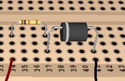
20 One 2010 A. Ganago Introduction Page 16 of 24

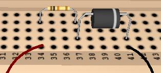
21 Two 2010 A. Ganago Introduction Page 17 of 24

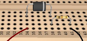
22 Three 2010 A. Ganago Introduction Page 18 of 24

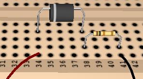
23 Four 2010 A. Ganago Introduction Page 19 of 24
24 = = = Lab 1: Introduction to Measurements with NI ELVIS II Voltage division The circuit shown on this diagram is called a voltage divider. Its output voltage equals: For example, if VBSB then 6 V, RB1B R V 2 OUT = V S R R Ω and RB2B 200 Ω, R 200 Ω ( ) ( ) ( ) 2 VOUT = VS = 6 V = 4 R1+ R Ω Ω V However, the same pair of resistors may be differently connected to the same source and the output, as shown on the second diagram: Then the output changes to: R 1 VOUT = VS R 1+ R Ω = 6 V = 2 V ( ) ( 100 Ω ) + ( 200 Ω ) Make sure to pay attention to all connections when you build your circuits in the lab. In DC measurements (when the source voltage is constant), the output voltage is measured with a voltmeter whose reference is at the ground node, and the probe is at the node where the two resistors connect to each other A. Ganago Introduction Page 20 of 24
 = V sin(2π f t) max or the same thing 2π V(t) = Vmax sin( t) T where f is frequency in hertz, and T is period in seconds.")
25 and and =100 = Lab 1: Introduction to Measurements with NI ELVIS II Voltage Division in AC Measurements AC measurements are made with voltages that vary with time. Most often, we use sinusoidal voltages V(t) = V sin(2π f t) max or the same thing 2π V(t) = Vmax sin( t) T where f is frequency in hertz, and T is period in seconds. In AC measurements, the source on the diagram above is a function generator, which produces sine waves at the desired frequency f and peak voltage VBmaxB, and the output voltage is measured with an oscilloscope. A good oscilloscope has two channels, or two independent inputs thus it can measure both VBSB VBOUTB at the same time. On this screenshot, the green line corresponds to VBSB the blue line to VBOUT B. These waveforms were obtained with a voltage divider RB1B Ω and RB2B 200 Ω. Note that the formulas for voltage division remain the same as discussed above A. Ganago Introduction Page 21 of 24
26 When the two resistors are swapped, as shown on this diagram, the output waveform changes, as you can see on the screenshot below, which was also obtained with the NI ELVIS oscilloscope. For comparison between DC measurements (where the source voltage is constant) and AC measurements (where the source voltage is sinusoidal), you may think of an oscilloscope as a voltmeter that can rapidly read varying signals and is connected to the circuit in exactly the same way for both types of measurements. Note that the oscilloscope control panel to the right of the plot on the screenshot allows you to choose Volts/Div (volts per division on the vertical scale) in Channel 0 and in Channel 1 independently (here, they both equal 500 mv/div). The horizontal scale is determined by the choice of Time/Div, the same for both channels. Also note that the NI ELVIS oscilloscope automatically measures and displays the amplitude of signal in each channel in Vp-p, or volts peak-to-peak (Vp-p = 2 VBmax Bfor the sine wave), and the frequency in hertz (Hz). The readings of frequency on this screenshot agree with the 1 khz setting on the function generator. The displayed amplitudes of the input and output signals allow you to verify the equations for voltage division in this experiment A. Ganago Introduction Page 22 of 24
27 = zero. Lab 1: Introduction to Measurements with NI ELVIS II AC Measurements with a Resistor LED Circuit Since an LED is a nonohmic circuit element, the output voltage is not directly proportional to the input voltage. According to the offset model, our diode conducts only when the source voltage exceeds VBD0B ~ 1.7 V. It means that, when the source voltage remains negative or positive but below VBD0 B, the current does not flow through this circuit thus, from Ohm s law, the voltage measured across the load resistor remains RBLB The screenshot below shows the output voltage measured across the load resistor RBLB 200 Ω in a circuit with an LED. Note that the overall shape of the output waveform agrees with our expectations: when the input voltage is negative or positive but below ~1.7 V, the output is dead zero; when the input exceeds ~1.7 V, the output looks like a cropped sine wave, similar to V = V 1.7 V. OUT IN ( ) 2010 A. Ganago Introduction Page 23 of 24

28 From comparison between the input and output waveforms, one can estimate the value of the offset voltage as VD0 = VIN, MAX VOUT, MAX There are at least two ways to determine the necessary numerical values of V IN, MAX and from the lab data: V OUT, MAX 1. Measure the two peak values shown with the arrows, using the Volts/Div value or directly with cursors of the oscilloscope 2. Use the numerical readouts of both peak-to-peak amplitudes, along with VIN, peak-to-peak the relationships: V IN, MAX = (valid because the input is a sine wave) 2 and V = V (because the output is zero or positive). OUT, MAX OUT, peak-to-peak The effect observed on the screenshot of page 22 is called rectification: the input voltage of alternating polarity is converted to the output voltage of constant polarity. The huge difference between V and results from the large VBD0B IN, MAX VOUT, MAX and the small V. In practical rectifier circuits, V is larger, and VBD0 Bis usually smaller. IN, MAX IN, MAX 2010 A. Ganago Introduction Page 24 of 24
29 Pre-Lab The pre-lab includes 6 problems. Make sure to complete them all before the lab. 1. Identify which diagram on page 15 for the circuits with a resistor and an LED (repeated here for your convenience) corresponds to each 3-D picture of the prototyping board on pages Write a brief explanation of how you found which circuit is which, for diagram C. A B C D 2010 A. Ganago Pre-Lab Page 1 of 6
30 Pre-Lab (continued) 2. This sketch shows connections for the measurements of the voltage across and the current through a resistor. Note that all connections here are built in the air without a prototyping board. On the sketch below, show the same connections using nodes on the prototyping board; specifically, the power supply should be connected to the bus lines on the left and the resistor should be connected to individual nodes on the right. Draw connections for the measurements of the voltage across and the current through a resistor A. Ganago Pre-Lab Page 2 of 6
31 Pre-Lab (continued) 3. Draw connections for the measurements of the voltage across and the current through a forward-biased LED (be careful with the polarity). In this circuit, no load resistor is needed. The power supply should be connected to the bus lines on the left and the LED should be connected to individual nodes on the right A. Ganago Pre-Lab Page 3 of 6
32 Pre-Lab (continued) 4. Draw connections for the circuit with an LED and resistor shown on this diagram. The power supply should be connected to the bus lines on the left, the resistor and LED should be connected to the individual nodes on the right, and the voltmeter should measure the output voltage A. Ganago Pre-Lab Page 4 of 6
33 Pre-Lab (continued) 5. From the screenshots for voltage division given on pages 21 and 22, and from the circuits shown on these diagrams, calculate the ratios of resistances RB1B/RB2B and RB2B/RB1B. Compare the results of your calculations with the ratios of 100 Ω and 200 Ω resistances in the circuit. Calculate the percentage error: ( Measured) ( Expected) 100% Expected ( ) Here, Measured stands for what you obtain from experimental data on pages 20 and 21; Expected stands for what you found from the nominal values of 100 Ω and 200 Ω. For your reference, the peak-to peak voltages on the screenshots are: Channel 0 Channel 1 Channel 0 Channel 1 Page 21 Page V V V V 2010 A. Ganago Pre-Lab Page 5 of 6
34 Pre-Lab (continued) 6. From the screenshot on page 23, obtained with the circuit with a resistor and LED, determine the offset voltage VBD0 B. Use both methods explained on page 24; discuss their accuracy. For your reference, the peak-to peak voltages on the screenshot of Page 23 are: Channel 0 Channel V mv End of the pre-lab 2010 A. Ganago Pre-Lab Page 6 of 6
35 In-Lab Work NOTE 1: The NI ELVIS II unit has 2 power switches. The first one, located on the rear (next to the power cables), is used to supply power to the USB communications module within the NI ELVIS II. This power switch should remain on for the duration of the lab. You can tell that the first power switch is enabled by looking at the orange USB ENABLED LED located on top right hand corner of the ELIVS II. The second switch is located on the top of the NI ELVIS II and supplies power to the terminal strips located on the sides of the PB (the terminal strips can then be used to power your circuit). This second power switch should only be enabled when you are ready to begin testing your circuit and taking measurements. When you are building your circuit, this switch should be disabled in order to prevent damage to your circuit, the NI ELVIS II, and/or injury to yourself. You can tell that the second power switch is enabled by looking at the green POWER LED located on the top right hand corner of the NI ELVIS II. NOTE 2: The NI ELVIS II is a sensitive, precision instrument. It will respond quite extremely to seemingly minor/insignificant variations such as poor circuit connections. Make sure that all of your connections are correct and comfortable. Meaning that you should always use adequate space for you circuit (as opposed to cramming everything in as tight as you possibly can) and use wires which are long enough and which have a roughly 0.25 inch length of plastic coating removed on either end. Plastic Coating Exposed wire Good Bad Bad Bad 2010 A. Ganago In-Lab Page 1 of 14
36 Part 1: DC Measurements Build your own circuits on the PB Measure DC voltages and currents with NI ELVIS power supply and DMM, then with NI ELVIS Two-Wire Current Voltage Analyzer Section 1.1: Resistor Turn the NI ELVIS II on by flipping the switch on the rear of the NI ELVIS II (you should now see the orange USB READY light turned on. The green POWER light, which signifies power to the PB, should be off). Place a 200 Ω resistor on the PB in such a way that you create 2 distinct nodes. Connect the ground node of the resistor to the GROUND terminal strip (number 49 on the left hand side). Using a banana cable with alligator clips, connect the Variable Power Supplies SUPPY+ terminal strip (number 48) to the red DMM current input (labeled A and located on the left hand side of the white part of the NI ELVIS II). Complete the circuit by using another banana cable to connect the COM port of the DMM (located adjacent to the current input) to the positive node of the resistor. Turn the PB on (you should now see the green POWER LED turn on). On your PC, run the NI ELVISmx Instrument Launcher. Launch the Digital Multimeter (DMM) and the Variable Power Supply (VPS) by clicking their icons on the instrument launcher. In the DMM VI, click the blue A symbol to put the DMM in DC current mode, click the green arrow to run the VI. On the VPS VI, click the green arrow to run. You can now set a voltage by either rotating the SUPPLY + knob in the VPS VI, or entering a value in the box under the knob A. Ganago In-Lab Page 2 of 14
37 Take the following measurements of the voltage applied to the circuit and of the current through the 200 Ω resistor. Take data by hand. Fill the table: Voltage, V Current, ma Resistance calculated from Ohm s law, Ω Write a brief conclusion on whether Ohm s law applies to the resistor: 2010 A. Ganago In-Lab Page 3 of 14
38 Section 1.2: LED Turn off the power to the PB. Replace the resistor with a forward biased LED (maintain all the other connections from your previous measurements). Make sure you insert the LED with the correct polarity. Turn the PB back on. Using the DMM and VPS, take the following measurements. Take data by hand; fill the table: Voltage, V Current, ma Resistance calculated from Ohm s law, Ω Write a brief conclusion on whether Ohm s law applies to the resistor: 2010 A. Ganago In-Lab Page 4 of 14
, and connect the ground node of the resistor to the DMM/Impedance Analyzer s DUT- terminal")
39 Section 1.3: Current Voltage Measurement with the 2-Wire Analyzer Turn off power to the PB and remove all of your connections. Replace the LED with the 200 Ω resistor. Connect the positive node of the resistor to the DMM/Impedance Analyzer s DUT+ terminal strip (number 29), and connect the ground node of the resistor to the DMM/Impedance Analyzer s DUT- terminal strip (number 30). Turn the power to the PB back on. Launch the 2-Wire Current Voltage Analyzer from the NI ELVISmx Instrument Launcher. Set the following settings: Run the VI by clicking the green arrow. Log the data and create a printout of the plot. Turn off power to the PB and replace the resistor with a forward-biased LED. Make sure the polarity of the LED is correct! Turn the power to the PB back on and rerun the 2-Wire Current Voltage Analyzer VI (use the same settings). Log the results and create a printout of the plot A. Ganago In-Lab Page 5 of 14
40 = = and will Lab 1: Introduction to Measurements with NI ELVIS II Part 2: AC Measurements Build your own circuits on the PB, apply input AC voltages from NI ELVIS function generator and measure AC output voltages with NI ELVIS oscilloscope Observe rectification of the input AC voltage in the resistor LED circuit, and relate the waveforms obtained with oscilloscope to the current voltage curves obtained in DC measurements Section 2.1: Voltage Divider of 2 Resistors Turn off power to the PB and build the following circuit: Here, RB1B 100 Ω and RB2B 200 Ω. Recall from the lab introduction that in an AC circuit, VBSB be the function generator, and that measurements will be taken with the oscilloscope. Use Analog input 1 to measure VBSB Analog input 2 to measure VBOUT B. By measuring both the input signal and the output signal, you will be able to more easily see their relationship in the voltage divider circuit. The FGEN terminal strip is number 33, GROUND is number 49, and AI0+, AI0, AI1+, and AI1 are numbers 1 4 respectively. Once you have your circuit built, power on the PB A. Ganago In-Lab Page 6 of 14


41 From the NI ELVIS Instrument Launcher, launch the Function Generator (FGEN) and Oscilloscope (Scope). On the FGEN VI, set the following settings: Run the VI. Ignore the sweep settings. On the Scope VI, set the following settings: Run the VI. Adjust the Time/Div scale and the Volts/Div scale on each channel so that the waveforms are clearly displayed. Log the results and create a printout of the plot. Power off the PB A. Ganago In-Lab Page 7 of 14
42 = = Lab 1: Introduction to Measurements with NI ELVIS II Switch the two resistors to create the following circuit: Here, RB1B 100 Ω and RB2B 200 Ω. Power on the PB. Rerun the FGEN and Scope VIs with the same settings. Log the results and create a printout of the plot A. Ganago In-Lab Page 8 of 14
43 = = Lab 1: Introduction to Measurements with NI ELVIS II Section 2.2: Circuits with a Resistor and an LED Power off the PB and build the following circuit: Here RBLB 200 Ω. Power on the PB. Rerun the FGEN and Scope VIs with the same setting as you used in Part 2. Log the results and create a plot of the data. Power off the PB and switch the LED and resistor to create the following circuit: Here RBLB 200 Ω. Power on the PB. Rerun the FGEN and Scope VIs with the same setting as you used in Part 2. Log the results and create a plot of the data A. Ganago In-Lab Page 9 of 14
44 RBLB = Lab 1: Introduction to Measurements with NI ELVIS II Part 3: Explorations, for Extra Credit This is the end of the required lab. If you still have time and are curious, this part will guide you through further explorations (and you can earn some extra credit). If you are not going to continue with this part, power down your PB and the NI ELVIS II, and clean up your workstation. Section 3.1: Circuits with a Resistor and a Reversed-Biased LED Redo Section 2.2 with a reversed-biased LED (instead of the forward-biased one). Take data on the both circuits shown here. 200 Ω A. Ganago In-Lab Page 10 of 14
45 = Lab 1: Introduction to Measurements with NI ELVIS II Explorations, for Extra Credit (continued) Section 3.2: Circuits with a Resistor and an Opposing Pair of LEDs Redo Section 2.2 with a pair of opposing LEDs (instead of the forward-biased one). Take data on the both circuits shown here. RBLB 200 Ω A. Ganago In-Lab Page 11 of 14
46 = Lab 1: Introduction to Measurements with NI ELVIS II Explorations, for Extra Credit (continued) The next three sections allow you to explore both the response of your circuit to various conditions and the limitations of the NI ELVIS itself Section 3.3: Circuit Response to Sine Waves of Different Amplitudes Power off the PB and build the following circuit: Here RBLB 200 Ω. Power on the PB. Vary the amplitude of the input signal from the function generator (adjust the Volts/div on the oscilloscope to clearly view the signals). Notice how the output signal responds to the changing input. Try to make the output become a constant 0 V signal. Record the input amplitude which yields these results A. Ganago In-Lab Page 12 of 14
47 Section 3.4: Circuit Response to a Different Input Waveform Repeat Sections using a triangle waveform instead of a sine wave. To do this, click the red triangle wave button on the FGEN VI A. Ganago In-Lab Page 13 of 14
48 = Lab 1: Introduction to Measurements with NI ELVIS II Explorations, for Extra Credit (continued) Section 3.5: Circuit with Different Input Frequency Power off the PB and build the following circuit: Here RBLB 200 Ω. Power on the PB. Vary the frequency of the input signal from the function generator (adjust the Time/div on the oscilloscope to clearly view the signals). Notice how the output signal responds to the changing input. Record the input frequency where the output stops being sinusoidal. End of Lab 1. Power down your PB and NI ELVIS II and clean up your workstation A. Ganago In-Lab Page 14 of 14
49 Post-Lab Lab 1: Introduction to Measurements with NI ELVIS II REQUIRED 1. Based on your data obtained In-Lab Part 1, discuss the similarity and distinction of your data for the resistor and for the LED. Explain whether the data in your tables (Sections 1.1 and 1.2) are sufficient to prove that the resistor is ohmic, and the LED is nonohmic. Explain whether your I-V plots obtained with the 2-Wire Analyzer (Section 1.3) are sufficient to prove that the resistor is ohmic, and the LED is non-ohmic. 2. Based on your data obtained In-Lab Part 2, Section 2.1, for each of the two voltage VOUT dividers, compare the ratio obtained in the lab with that ratio obtained from the VIN theoretical formulas. Calculate the percentage difference, as you did in Pre-Lab #5. 3. Based on your data obtained In-Lab Part 2, Section 2.2, for each of the two circuits with a resistor and an LED, calculate the diode offset voltage. Briefly discuss the V D0 agreement between the two values of. V D0 4. Relate the value(s) of V D0 calculated in #3 above to the plot that you obtained In-Lab Part 1, Section 1.3. Discuss. The extra credit part is on the following page A. Ganago Post-Lab Page 1 of 2
50 Post-Lab (continued) EXPLORATIONS, FOR EXTRA CREDIT 5. Explain the data you obtained In-Lab Section 3.1. Write a brief statement on your comparison between this data and that in #3 above. 6. Explain your data obtained In-Lab Section 3.2. Briefly compare your data obtained with the two circuits. 7. Explain your data obtained In-Lab Section 3.3. If you have achieved dead zero output, explain how your circuit works under these conditions. 8. Explain the data you obtained In-Lab Section 3.4. Briefly discuss the circuit responses to sinusoidal and triangular input waveforms. 9. Discuss your data obtained In-Lab Section 3.5. Carefully describe whether you observed anything unexpected at high frequencies (strange waveforms, deviations from the offset diode model, etc.) A. Ganago Post-Lab Page 2 of 2
LAB EXPERIMENTS USING NI ELVIS II
 LAB EXPERIMENTS USING NI ELVIS II AND NI MULTISIM Alexander Ganago Jason Lee Sleight University of Michigan Ann Arbor Lab 3 Thevenin Equivalent Circuit; Beyond Parallel and Series 2010 A. Ganago Introduction
Name: Resistors and Basic Resistive Circuits. Objective: To gain experience with data acquisition proto-boards physical resistors. Table of Contents:
 Objective: To gain experience with data acquisition proto-boards physical resistors Table of Contents: Name: Resistors and Basic Resistive Circuits Pre-Lab Assignment 1 Background 2 National Instruments
Name: First-Order Response: RC Networks Objective: To gain experience with first-order response of RC circuits
 First-Order Response: RC Networks Objective: To gain experience with first-order response of RC circuits Table of Contents: Pre-Lab Assignment 2 Background 2 National Instruments MyDAQ 2 Resistors 3 Capacitors
Physics 120 Lab 1 (2018) - Instruments and DC Circuits
 - Instruments and DC Circuits") Physics 120 Lab 1 (2018) - Instruments and DC Circuits Welcome to the first laboratory exercise in Physics 120. Your state-of-the art equipment includes: Digital oscilloscope w/usb output for SCREENSHOTS.
Physics 120 Lab 1 (2018) - Instruments and DC Circuits Welcome to the first laboratory exercise in Physics 120. Your state-of-the art equipment includes: Digital oscilloscope w/usb output for SCREENSHOTS.
Figure 1 Diode schematic symbol (left) and physical representation (right)
 and physical representation (right)") Page 1/7 Revision 1 20-Jul-10 OBJECTIVES To reinforce the concepts behind diode circuit analysis Verification of diode theory and operation To understand certain diode applications, such as rectification
Page 1/7 Revision 1 20-Jul-10 OBJECTIVES To reinforce the concepts behind diode circuit analysis Verification of diode theory and operation To understand certain diode applications, such as rectification
Fig. 1. NI Elvis System
 Lab 2: Introduction to I Elvis Environment. Objectives: The purpose of this laboratory is to provide an introduction to the NI Elvis design and prototyping environment. Basic operations provided by Elvis
EE 210: CIRCUITS AND DEVICES
 EE 210: CIRCUITS AND DEVICES LAB #3: VOLTAGE AND CURRENT MEASUREMENTS This lab features a tutorial on the instrumentation that you will be using throughout the semester. More specifically, you will see
University of Jordan School of Engineering Electrical Engineering Department. EE 204 Electrical Engineering Lab
 University of Jordan School of Engineering Electrical Engineering Department EE 204 Electrical Engineering Lab EXPERIMENT 1 MEASUREMENT DEVICES Prepared by: Prof. Mohammed Hawa EXPERIMENT 1 MEASUREMENT
LAB 2 Circuit Tools and Voltage Waveforms
 LAB 2 Circuit Tools and Voltage Waveforms OBJECTIVES 1. Become familiar with a DC power supply and setting the output voltage. 2. Learn how to measure voltages & currents using a Digital Multimeter. 3.
ET1210: Module 5 Inductance and Resonance
 Part 1 Inductors Theory: When current flows through a coil of wire, a magnetic field is created around the wire. This electromagnetic field accompanies any moving electric charge and is proportional to
LAB I. INTRODUCTION TO LAB EQUIPMENT
 LAB I. INTRODUCTION TO LAB EQUIPMENT 1. OBJECTIVE In this lab you will learn how to properly operate the basic bench equipment used for characterizing active devices: 1. Oscilloscope (Keysight DSOX 1102A),
UNIVERSITY OF NORTH CAROLINA AT CHARLOTTE Department of Electrical and Computer Engineering
 UNIVERSITY OF NORTH CAROLINA AT CHARLOTTE Department of Electrical and Computer Engineering EXPERIMENT 2 BASIC CIRCUIT ELEMENTS OBJECTIVES The purpose of this experiment is to familiarize the student with
Lab Reference Manual. ECEN 326 Electronic Circuits. Texas A&M University Department of Electrical and Computer Engineering
 Lab Reference Manual ECEN 326 Electronic Circuits Texas A&M University Department of Electrical and Computer Engineering Contents 1. Circuit Analysis in PSpice 3 1.1 Transient and DC Analysis 3 1.2 Measuring
Group: Names: Resistor Band Colors Measured Value ( ) R 1 : 1k R 2 : 1k R 3 : 2k R 4 : 1M R 5 : 1M
 R 1 : 1k R 2 : 1k R 3 : 2k R 4 : 1M R 5 : 1M") 2.4 Laboratory Procedure / Summary Sheet Group: Names: (1) Select five separate resistors whose nominal values are listed below. Record the band colors for each resistor in the table below. Then connect
2.4 Laboratory Procedure / Summary Sheet Group: Names: (1) Select five separate resistors whose nominal values are listed below. Record the band colors for each resistor in the table below. Then connect
ECE 53A: Fundamentals of Electrical Engineering I
 ECE 53A: Fundamentals of Electrical Engineering I Laboratory Assignment #1: Instrument Operation, Basic Resistor Measurements and Kirchhoff s Laws Fall 2007 General Guidelines: - Record data and observations
Laboratory 2 (drawn from lab text by Alciatore)
") Laboratory 2 (drawn from lab text by Alciatore) Instrument Familiarization and Basic Electrical Relations Required Components: 2 1k resistors 2 1M resistors 1 2k resistor Objectives This exercise is designed
Laboratory 2 (drawn from lab text by Alciatore) Instrument Familiarization and Basic Electrical Relations Required Components: 2 1k resistors 2 1M resistors 1 2k resistor Objectives This exercise is designed
Laboratory 4. Bandwidth, Filters, and Diodes
 Laboratory 4 Bandwidth, Filters, and Diodes Required Components: k resistor 0. F capacitor N94 small-signal diode LED 4. Objectives In the previous laboratory exercise you examined the effects of input
Practical 2P12 Semiconductor Devices
 Practical 2P12 Semiconductor Devices What you should learn from this practical Science This practical illustrates some points from the lecture courses on Semiconductor Materials and Semiconductor Devices
LAB II. INTRODUCTION TO LAB EQUIPMENT
 1. OBJECTIVE LAB II. INTRODUCTION TO LAB EQUIPMENT In this lab you will learn how to properly operate the oscilloscope Keysight DSOX1102A, the Keithley Source Measure Unit (SMU) 2430, the function generator
Physics 323. Experiment # 1 - Oscilloscope and Breadboard
 Physics 323 Experiment # 1 - Oscilloscope and Breadboard Introduction In order to familiarise yourself with the laboratory equipment, a few simple experiments are to be performed. References: XYZ s of
Lab 2: Linear and Nonlinear Circuit Elements and Networks
 OPTI 380B Intermediate Optics Laboratory Lab 2: Linear and Nonlinear Circuit Elements and Networks Objectives: Lean how to use: Function of an oscilloscope probe. Characterization of capacitors and inductors
Wave Measurement & Ohm s Law
 Wave Measurement & Ohm s Law Marking scheme : Methods & diagrams : 2 Graph plotting : 1 Tables & analysis : 2 Questions & discussion : 3 Performance : 2 Aim: Various types of instruments are used by engineers
Lab 3: AC Low pass filters (version 1.3)
") Lab 3: AC Low pass filters (version 1.3) WARNING: Use electrical test equipment with care! Always double-check connections before applying power. Look for short circuits, which can quickly destroy expensive
Lab 3: AC Low pass filters (version 1.3) WARNING: Use electrical test equipment with care! Always double-check connections before applying power. Look for short circuits, which can quickly destroy expensive
Lab 13 AC Circuit Measurements
 Lab 13 AC Circuit Measurements Objectives concepts 1. what is impedance, really? 2. function generator and oscilloscope 3. RMS vs magnitude vs Peak-to-Peak voltage 4. phase between sinusoids skills 1.
Lab 2: Introduction to NI ELVIS, Multisim, and LabVIEW
 Page 1 of 19 Lab 2: Introduction to NI ELVIS, Multisim, and LabVIEW Laboratory Goals Familiarize students with the National Instruments hardware ELVIS Learn about the LabVIEW programming environment Demonstrate
Physics 4B, Lab # 2 Circuit Tools and Voltage Waveforms
 Physics 4B, Lab # 2 Circuit Tools and Voltage Waveforms OBJECTIVES 1. Become familiar with a DC power supply and setting the output voltage. 2. Learn how to measure voltages & currents using a Digital
Laboratory Project 1a: Power-Indicator LED's
 2240 Laboratory Project 1a: Power-Indicator LED's Abstract-You will construct and test two LED power-indicator circuits for your breadboard in preparation for building the Electromyogram circuit in Lab
Lab #1 Lab Introduction
 Cir cuit s 212 Lab Lab #1 Lab Introduction Special Information for this Lab s Report Because this is a one-week lab, please hand in your lab report for this lab at the beginning of next week s lab. The
UNIVERSITY OF TECHNOLOGY, JAMAICA SCHOOL OF ENGENEERING. Electrical Engineering Science. Laboratory Manual
 UNIVERSITY OF TECHNOLOGY, JAMAICA SCHOOL OF ENGENEERING Electrical Engineering Science Laboratory Manual Table of Contents Experiment #1 OHM S LAW... 3 Experiment # 2 SERIES AND PARALLEL CIRCUITS... 8
DC CIRCUITS AND OHM'S LAW
 July 15, 2008 DC Circuits and Ohm s Law 1 Name Date Partners DC CIRCUITS AND OHM'S LAW AMPS - VOLTS OBJECTIVES OVERVIEW To learn to apply the concept of potential difference (voltage) to explain the action
Prelab 6: Biasing Circuitry
 Prelab 6: Biasing Circuitry Name: Lab Section: R 1 R 2 V OUT Figure 1: Resistive divider voltage source 1. Consider the resistor network shown in Figure 1. Let = 10 V, R 1 = 9.35 kω, and R 2 = 650 Ω. We
Lab 1: Basic Lab Equipment and Measurements
 Abstract: Lab 1: Basic Lab Equipment and Measurements This lab exercise introduces the basic measurement instruments that will be used throughout the course. These instruments include multimeters, oscilloscopes,
Oregon State University Lab Session #1 (Week 3)
") Oregon State University Lab Session #1 (Week 3) ENGR 201 Electrical Fundamentals I Equipment and Resistance Winter 2016 EXPERIMENTAL LAB #1 INTRO TO EQUIPMENT & OHM S LAW This set of laboratory experiments
Oregon State University Lab Session #1 (Week 3) ENGR 201 Electrical Fundamentals I Equipment and Resistance Winter 2016 EXPERIMENTAL LAB #1 INTRO TO EQUIPMENT & OHM S LAW This set of laboratory experiments
Laboratory 3 (drawn from lab text by Alciatore)
") Laboratory 3 (drawn from lab text by Alciatore) The Oscilloscope Required Components: 1 10 resistor 2 100 resistors 2 lk resistors 1 2k resistor 2 4.7M resistors 1 0.F capacitor 1 0.1 F capacitor 1 1.0uF
Laboratory 3 (drawn from lab text by Alciatore) The Oscilloscope Required Components: 1 10 resistor 2 100 resistors 2 lk resistors 1 2k resistor 2 4.7M resistors 1 0.F capacitor 1 0.1 F capacitor 1 1.0uF
Revision: Jan 29, E Main Suite D Pullman, WA (509) Voice and Fax
 Voice and Fax") Revision: Jan 29, 2011 215 E Main Suite D Pullman, WA 99163 (509) 334 6306 Voice and Fax Overview The purpose of this lab assignment is to provide users with an introduction to some of the equipment which
Revision: Jan 29, 2011 215 E Main Suite D Pullman, WA 99163 (509) 334 6306 Voice and Fax Overview The purpose of this lab assignment is to provide users with an introduction to some of the equipment which
INTRODUCTION TO ENGINEERING AND LABORATORY EXPERIENCE Spring, 2015
 INTRODUCTION TO ENGINEERING AND LABORATORY EXPERIENCE Spring, 2015 Saeid Rahimi, Ph.D. Jack Ou, Ph.D. Engineering Science Sonoma State University A SONOMA STATE UNIVERSITY PUBLICATION CONTENTS 1 Electronic
332:223 Principles of Electrical Engineering I Laboratory Experiment #2 Title: Function Generators and Oscilloscopes Suggested Equipment:
 RUTGERS UNIVERSITY The State University of New Jersey School of Engineering Department Of Electrical and Computer Engineering 332:223 Principles of Electrical Engineering I Laboratory Experiment #2 Title:
UNIVERSITY OF TECHNOLOGY, JAMAICA School of Engineering -
 UNIVERSITY OF TECHNOLOGY, JAMAICA School of Engineering - Electrical Engineering Science Laboratory Manual Table of Contents Safety Rules and Operating Procedures... 3 Troubleshooting Hints... 4 Experiment
LAB 1: Familiarity with Laboratory Equipment (_/10)
") LAB 1: Familiarity with Laboratory Equipment (_/10) PURPOSE o gain familiarity with basic laboratory equipment oscilloscope, oscillator, multimeter and electronic components. EQUIPMEN (i) Oscilloscope
LAB 1: Familiarity with Laboratory Equipment (_/10) PURPOSE o gain familiarity with basic laboratory equipment oscilloscope, oscillator, multimeter and electronic components. EQUIPMEN (i) Oscilloscope
Voltage Current and Resistance II
 Voltage Current and Resistance II Equipment: Capstone with 850 interface, analog DC voltmeter, analog DC ammeter, voltage sensor, RLC circuit board, 8 male to male banana leads 1 Purpose This is a continuation
ECE 2006 University of Minnesota Duluth Lab 11. AC Circuits
 1. Objective AC Circuits In this lab, the student will study sinusoidal voltages and currents in order to understand frequency, period, effective value, instantaneous power and average power. Also, the
Evaluation Board for the AAT2784 Three-Channel Step-down DC/DC Converter
 Introduction EVALUATION BOARD DATA SHEET EV57 The AAT2784 evaluation board provides a platform for test and evaluation of the AAT2784 -channel.8mhz step-down converter. The input voltages (V P ) of the
Chapter 1: DC circuit basics
 Chapter 1: DC circuit basics Overview Electrical circuit design depends first and foremost on understanding the basic quantities used for describing electricity: voltage, current, and power. In the simplest
Physics 1051 Laboratory #4 DC Circuits and Ohm s Law. DC Circuits and Ohm s Law
 DC Circuits and Ohm s Law Contents Part I: Objective Part II: Introduction Part III: Apparatus and Setup Part IV: Measurements Part V: Analysis Part VI: Summary and Conclusions Part I: Objective In this
Laboratory 2. Lab 2. Instrument Familiarization and Basic Electrical Relations. Required Components: 2 1k resistors 2 1M resistors 1 2k resistor
 Laboratory 2 nstrument Familiarization and Basic Electrical Relations Required Components: 2 1k resistors 2 1M resistors 1 2k resistor 2.1 Objectives This exercise is designed to acquaint you with the
Experiment 2. Ohm s Law. Become familiar with the use of a digital voltmeter and a digital ammeter to measure DC voltage and current.
 Experiment 2 Ohm s Law 2.1 Objectives Become familiar with the use of a digital voltmeter and a digital ammeter to measure DC voltage and current. Construct a circuit using resistors, wires and a breadboard
EE2210 Laboratory Project 1 Fall 2013 Function Generator and Oscilloscope
 EE2210 Laboratory Project 1 Fall 2013 Function Generator and Oscilloscope For students to become more familiar with oscilloscopes and function generators. Pre laboratory Work Read the TDS 210 Oscilloscope
Lab 3 DC CIRCUITS AND OHM'S LAW
 43 Name Date Partners Lab 3 DC CIRCUITS AND OHM'S LAW AMPS + - VOLTS OBJECTIVES To learn to apply the concept of potential difference (voltage) to explain the action of a battery in a circuit. To understand
ECE3204 D2015 Lab 1. See suggested breadboard configuration on following page!
 ECE3204 D2015 Lab 1 The Operational Amplifier: Inverting and Non-inverting Gain Configurations Gain-Bandwidth Product Relationship Frequency Response Limitation Transfer Function Measurement DC Errors
Lab Session 4 Hardware
 Lab Session 4 Hardware Objectives: Upon completion of this experiment, the student will be able to: -Verifying of Transient response, two port network and Fourier analysis circuits Equipment and Components
Integrators, differentiators, and simple filters
 BEE 233 Laboratory-4 Integrators, differentiators, and simple filters 1. Objectives Analyze and measure characteristics of circuits built with opamps. Design and test circuits with opamps. Plot gain vs.
Experiment 3. Ohm s Law. Become familiar with the use of a digital voltmeter and a digital ammeter to measure DC voltage and current.
 Experiment 3 Ohm s Law 3.1 Objectives Become familiar with the use of a digital voltmeter and a digital ammeter to measure DC voltage and current. Construct a circuit using resistors, wires and a breadboard
LAB I. INTRODUCTION TO LAB EQUIPMENT
 1. OBJECTIVE LAB I. INTRODUCTION TO LAB EQUIPMENT In this lab you will learn how to properly operate the oscilloscope Agilent MSO6032A, the Keithley Source Measure Unit (SMU) 2430, the function generator
Pre-Laboratory Assignment
 Measurement of Electrical Resistance and Ohm's Law PreLaboratory Assignment Read carefully the entire description of the laboratory and answer the following questions based upon the material contained
Notes on Experiment #1
 Notes on Experiment #1 Bring graph paper (cm cm is best) From this week on, be sure to print a copy of each experiment and bring it with you to lab. There will not be any experiment copies available in
Lab 3: RC Circuits. Construct circuit 2 in EveryCircuit. Set values for the capacitor and resistor to match those in figure 2 and set the frequency to
 Lab 3: RC Circuits Prelab Deriving equations for the output voltage of the voltage dividers you constructed in lab 2 was fairly simple. Now we want to derive an equation for the output voltage of a circuit
Precalculations Individual Portion Introductory Lab: Basic Operation of Common Laboratory Instruments
 Name: Date of lab: Section number: M E 345. Lab 1 Precalculations Individual Portion Introductory Lab: Basic Operation of Common Laboratory Instruments Precalculations Score (for instructor or TA use only):
Class #9: Experiment Diodes Part II: LEDs
 Class #9: Experiment Diodes Part II: LEDs Purpose: The objective of this experiment is to become familiar with the properties and uses of LEDs, particularly as a communication device. This is a continuation
INTRODUCTION TO NI ELVIS II
 DEPARTMENT OF ELECTRONICS AGH UST LABORATORY OF ELECTRONIC DEVICES INTRODUCTION TO NI ELVIS II REV. 1.0 1. ABOUT NI ELVIS III The NI ELVIS system is built using NI hardware and software technology entirely,
E84 Lab 3: Transistor
 E84 Lab 3: Transistor Cherie Ho and Siyi Hu April 18, 2016 Transistor Testing 1. Take screenshots of both the input and output characteristic plots observed on the semiconductor curve tracer with the following
Class #8: Experiment Diodes Part I
 Class #8: Experiment Diodes Part I Purpose: The objective of this experiment is to become familiar with the properties and uses of diodes. We used a 1N914 diode in two previous experiments, but now we
AC CURRENTS, VOLTAGES, FILTERS, and RESONANCE
 July 22, 2008 AC Currents, Voltages, Filters, Resonance 1 Name Date Partners AC CURRENTS, VOLTAGES, FILTERS, and RESONANCE V(volts) t(s) OBJECTIVES To understand the meanings of amplitude, frequency, phase,
Precalculations Individual Portion Filter Lab: Building and Testing Electrical Filters
 Name: Date of lab: Section number: M E 345. Lab 6 Precalculations Individual Portion Filter Lab: Building and Testing Electrical Filters Precalculations Score (for instructor or TA use only): / 20 1. (4)
THE BREADBOARD; DC POWER SUPPLY; RESISTANCE OF METERS; NODE VOLTAGES AND EQUIVALENT RESISTANCE; THÉVENIN EQUIVALENT CIRCUIT
 THE BREADBOARD; DC POWER SUPPLY; RESISTANCE OF METERS; NODE VOLTAGES AND EQUIVALENT RESISTANCE; THÉVENIN EQUIVALENT CIRCUIT YOUR NAME GTA S SIGNATURE LAB MEETING TIME Objectives: To correctly operate the
DC Electric Circuits: Resistance and Ohm s Law
 DC Electric Circuits: Resistance and Ohm s Law Goals and Introduction Our society is very reliant on electric phenomena, perhaps most so on the utilization of electric circuits. For much of our world to
the reactance of the capacitor, 1/2πfC, is equal to the resistance at a frequency of 4 to 5 khz.
 EXPERIMENT 12 INTRODUCTION TO PSPICE AND AC VOLTAGE DIVIDERS OBJECTIVE To gain familiarity with PSPICE, and to review in greater detail the ac voltage dividers studied in Experiment 14. PROCEDURE 1) Connect
Welcome to your second Electronics Laboratory Session. In this session you will learn about how to use resistors, capacitors and inductors to make
 Welcome to your second Electronics Laboratory Session. In this session you will learn about how to use resistors, capacitors and inductors to make simple circuits. You will find out how these circuits
BME/ISE 3511 Laboratory One - Laboratory Equipment for Measurement. Introduction to biomedical electronic laboratory instrumentation and measurements.
 BME/ISE 3511 Laboratory One - Laboratory Equipment for Measurement Learning Objectives: Introduction to biomedical electronic laboratory instrumentation and measurements. Supplies and Components: Breadboard
Sept 13 Pre-lab due Sept 12; Lab memo due Sept 19 at the START of lab time, 1:10pm
 Sept 13 Pre-lab due Sept 12; Lab memo due Sept 19 at the START of lab time, 1:10pm EGR 220: Engineering Circuit Theory Lab 1: Introduction to Laboratory Equipment Pre-lab Read through the entire lab handout
2 Oscilloscope Familiarization
 Lab 2 Oscilloscope Familiarization What You Need To Know: Voltages and currents in an electronic circuit as in a CD player, mobile phone or TV set vary in time. Throughout the course you will investigate
ECE 2274 Lab 2. Your calculator will have a setting that will automatically generate the correct format.
 ECE 2274 Lab 2 Forward (DO NOT TURN IN) You are expected to use engineering exponents for all answers (p,n,µ,m, N/A, k, M, G) and to give each with a precision between one and three leading digits and
DC and AC Circuits. Objective. Theory. 1. Direct Current (DC) R-C Circuit
 R-C Circuit") [International Campus Lab] Objective Determine the behavior of resistors, capacitors, and inductors in DC and AC circuits. Theory ----------------------------- Reference -------------------------- Young
[International Campus Lab] Objective Determine the behavior of resistors, capacitors, and inductors in DC and AC circuits. Theory ----------------------------- Reference -------------------------- Young
LABORATORY 4. Palomar College ENGR210 Spring 2017 ASSIGNED: 3/21/17
 LABORATORY 4 ASSIGNED: 3/21/17 OBJECTIVE: The purpose of this lab is to evaluate the transient and steady-state circuit response of first order and second order circuits. MINIMUM EQUIPMENT LIST: You will
Sonoma State University Department of Engineering Science Spring 2017
 EE 110 Introduction to Engineering & Laboratory Experience Saeid Rahimi, Ph.D. Lab 4 Introduction to AC Measurements (I) AC signals, Function Generators and Oscilloscopes Function Generator (AC) Battery
General Lab Notebook instructions (from syllabus)
") Physics 310 Lab 1: DC Circuits Equipment: Digital Multimeter, 5V Supply, Breadboard, two 1 k, 2.7 k, 5.1 k, 10 k, two Decade Resistor Box, potentiometer, 10 k Thermistor, Multimeter Owner s Manual General
Physics 310 Lab 1: DC Circuits Equipment: Digital Multimeter, 5V Supply, Breadboard, two 1 k, 2.7 k, 5.1 k, 10 k, two Decade Resistor Box, potentiometer, 10 k Thermistor, Multimeter Owner s Manual General
EE 2274 DIODE OR GATE & CLIPPING CIRCUIT
 EE 2274 DIODE OR GATE & CLIPPING CIRCUIT Prelab Part I: Wired Diode OR Gate LTspice use 1N4002 1. Design a diode OR gate, Figure 1 in which the maximum current thru R1 I R1 = 9mA assume Vin = 5Vdc. Design
Group: Names: (1) In this step you will examine the effects of AC coupling of an oscilloscope.
 In this step you will examine the effects of AC coupling of an oscilloscope.") 3.5 Laboratory Procedure / Summary Sheet Group: Names: (1) In this step you will examine the effects of AC coupling of an oscilloscope. Set the function generator to produce a 5 V pp 1kHz sinusoidal output.
3.5 Laboratory Procedure / Summary Sheet Group: Names: (1) In this step you will examine the effects of AC coupling of an oscilloscope. Set the function generator to produce a 5 V pp 1kHz sinusoidal output.
BME 3512 Bioelectronics Laboratory Five - Operational Amplifiers
 BME 351 Bioelectronics Laboratory Five - Operational Amplifiers Learning Objectives: Be familiar with the operation of a basic op-amp circuit. Be familiar with the characteristics of both ideal and real
Notes on Experiment #3
 Notes on Experiment #3 This week you learn to measure voltage, current, and resistance with the digital multimeter (DMM) You must practice measuring each of these quantities (especially current) as much
Lab 7 LEDs to the Rescue!
 Lab 7 LEDs to the Rescue! Figure 7.0. Stoplights with LabVIEW Indicators Have you ever sat in your car stopped at a city intersection waiting for the stoplight to change and wondering how long the red
BME/ISE 3512 Bioelectronics. Laboratory Five - Operational Amplifiers
 BME/ISE 3512 Bioelectronics Laboratory Five - Operational Amplifiers Learning Objectives: Be familiar with the operation of a basic op-amp circuit. Be familiar with the characteristics of both ideal and
1.0 Introduction to VirtualBench
 Table of Contents 1.0 Introduction to VirtualBench... 3 1. 1 VirtualBench in the Laboratory... 3 1.2 VirtualBench Specifications... 4 1.3 Introduction to VirtualBench Getting Started Guide Lab Exercises...
Lab 3: Kirchhoff's Laws and Basic Instrumentation
 Lab 3: Kirchhoff's Laws and Basic Instrumentation By: Gary A. Ybarra Christopher E. Cramer Duke Universty Department of Electrical and Computer Engineering Durham, NC 1. Purpose The purpose of this exercise
Introduction to Electronic Equipment
 Introduction to Electronic Equipment INTRODUCTION This semester you will be exploring electricity and magnetism. In order to make your time in here more instructive we ve designed this laboratory exercise
EXAMPLE. Use this jack for the red test lead when measuring. current from 0 to 200mA. Figure P-1
 Digital Multimeters ON / OFF power switch Continuity / Diode Test Function Resistance Function Ranges from 200Ω to 200MΩ Transistor Test Function DC Current Function Ranges from 2mA to 20A. AC Current
The oscilloscope and RC filters
 (ta initials) first name (print) last name (print) brock id (ab17cd) (lab date) Experiment 4 The oscilloscope and C filters The objective of this experiment is to familiarize the student with the workstation
The Oscilloscope. Vision is the art of seeing things invisible. J. Swift ( ) OBJECTIVE To learn to operate a digital oscilloscope.
 OBJECTIVE To learn to operate a digital oscilloscope.") The Oscilloscope Vision is the art of seeing things invisible. J. Swift (1667-1745) OBJECTIVE To learn to operate a digital oscilloscope. THEORY The oscilloscope, or scope for short, is a device for drawing
The Oscilloscope Vision is the art of seeing things invisible. J. Swift (1667-1745) OBJECTIVE To learn to operate a digital oscilloscope. THEORY The oscilloscope, or scope for short, is a device for drawing
ECE 2274 Lab 2 (Network Theorems)
") ECE 2274 Lab 2 (Network Theorems) Forward (DO NOT TURN IN) You are expected to use engineering exponents for all answers (p,n,µ,m, N/A, k, M, G) and to give each with a precision between one and three
ECE 2274 Lab 2 (Network Theorems) Forward (DO NOT TURN IN) You are expected to use engineering exponents for all answers (p,n,µ,m, N/A, k, M, G) and to give each with a precision between one and three
Chapter 1: DC circuit basics
 Chapter 1: DC circuit basics Overview Electrical circuit design depends first and foremost on understanding the basic quantities used for describing electricity: Voltage, current, and power. In the simplest
Introduction to basic laboratory instruments
 BEE 233 Laboratory-1 Introduction to basic laboratory instruments 1. Objectives To learn safety procedures in the laboratory. To learn how to use basic laboratory instruments: power supply, function generator,
Oscilloscope How To.
 Oscilloscope How To by amandaghassaei on April 9, 2012 Author:amandaghassaei uh-man-duh-guss-eye-dot-com I'm a grad student at the Center for Bits and Atoms at MIT Media Lab. Before that I worked at Instructables,
APPENDIX D DISCUSSION OF ELECTRONIC INSTRUMENTS
 APPENDIX D DISCUSSION OF ELECTRONIC INSTRUMENTS DC POWER SUPPLIES We will discuss these instruments one at a time, starting with the DC power supply. The simplest DC power supplies are batteries which
Experiment 15: Diode Lab Part 1
 Experiment 15: Diode Lab Part 1 Purpose Theory Overview EQUIPMENT NEEDED: Computer and Science Workshop Interface Power Amplifier (CI-6552A) (2) Voltage Sensor (CI-6503) AC/DC Electronics Lab Board (EM-8656)
Lab 9: Operational amplifiers II (version 1.5)
") Lab 9: Operational amplifiers II (version 1.5) WARNING: Use electrical test equipment with care! Always double-check connections before applying power. Look for short circuits, which can quickly destroy
Lab 9: Operational amplifiers II (version 1.5) WARNING: Use electrical test equipment with care! Always double-check connections before applying power. Look for short circuits, which can quickly destroy
Experiment Guide: RC/RLC Filters and LabVIEW
 Description and ackground Experiment Guide: RC/RLC Filters and LabIEW In this lab you will (a) manipulate instruments manually to determine the input-output characteristics of an RC filter, and then (b)
Electric Circuit Fall 2017 Lab3 LABORATORY 3. Diode. Guide
 LABORATORY 3 Diode Guide Diodes Overview Diodes are mostly used in practice for emitting light (as Light Emitting Diodes, LEDs) or controlling voltages in various circuits. Typical diode packages in same
Oscilloscope Measurements
 PC1143 Physics III Oscilloscope Measurements 1 Purpose Investigate the fundamental principles and practical operation of the oscilloscope using signals from a signal generator. Measure sine and other waveform
LABORATORY 3: Transient circuits, RC, RL step responses, 2 nd Order Circuits
 LABORATORY 3: Transient circuits, RC, RL step responses, nd Order Circuits Note: If your partner is no longer in the class, please talk to the instructor. Material covered: RC circuits Integrators Differentiators
A semester of Experiments for ECE 225
 A semester of Experiments for ECE 225 Contents General Lab Instructions... 3 Notes on Experiment #1... 4 ECE 225 Experiment #1 Introduction to the function generator and the oscilloscope... 5 Notes on
Laboratory Exercise 6 THE OSCILLOSCOPE
 Introduction Laboratory Exercise 6 THE OSCILLOSCOPE The aim of this exercise is to introduce you to the oscilloscope (often just called a scope), the most versatile and ubiquitous laboratory measuring