Power Over Ethernet (PoE) Part 1 What is it?, How is it used?, and Lightning Field Failure Analysis
|
|
|
- Opal Montgomery
- 6 years ago
- Views:
Transcription

1 Power Over Ethernet (PoE) Part 1 What is it?, How is it used?, and Lightning Field Failure Analysis Jim Wiese Senior Compliance Engineer ADTRAN, Inc. 901 Explorer Blvd. Huntsville, AL office cell Jim.wiese@adtran.com
2 Definition Power over Ethernet (PoE) describes any of several standardized or proprietary Ethernet systems which carry electrical power along with data on Cat 3 or higher type cable. This allows a single 8 conductor cable to provide both data connection and electrical power to devices such as IP Phones, IP Cameras, IP monitoring equipment, and wireless access points. PoE allows data communications up to 100M ( 330 feet). Power may be carried on the same conductors as the data, or it may be carried on dedicated conductors in the same cable. The system or network circuit consists of a PSE (Power Source Equipment) and a PD (Powered Equipment)
 or data pairs Mode A and Mode B Powering schemes Voltage limits are always under 60 Vdc (SELV, ES1) Current and Power are tightly controlled by IEEE standards (IEEE 802.3af & 802.")
3 Characteristics of PoE Similar topology to traditional T1 Span Powering Uses 2 Pairs for power (10/100 baset, GigE) Proprietary system might supply power on 4 pairs Power can be on unused pairs (10/100 baset) or data pairs Mode A and Mode B Powering schemes Voltage limits are always under 60 Vdc (SELV, ES1) Current and Power are tightly controlled by IEEE standards (IEEE 802.3af & 802.3at) Type 1 Limits PSE output power to 15.4W (af /at) Type 2 (PoE+) Limits PSE output power of 30.0W (at)
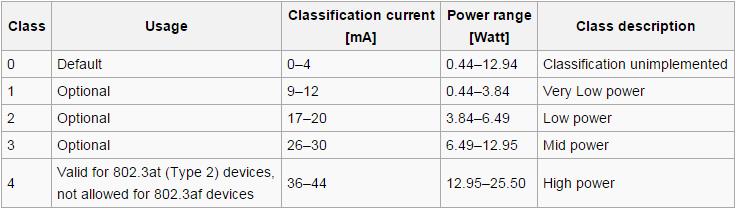

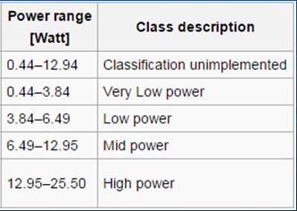
4 Characteristics of PoE PD Power Level Classes for PoE


5 Schematics of PoE Mode A and Mode B Powering for 10/100 baset

6 Schematics of PoE Powering for GigE


7 Wiring of PoE Mode A and Mode B Wiring and Pinouts
8 Alternative method of PoE Power injection In certain instances, the PC, switch or router only have regular Ethernet ports without PoE. In those cases a PoE midspan injector can be used.
9 Handshaking, Protection and Powering Protocol The PSE, not the PD, decides whether power mode A or B shall be used. PDs that implement only Mode A or Mode B are disallowed by the standard. The PSE can implement mode A or B or both. A PD indicates that it is standards-compliant by placing a 25 kω resistor between the powered pairs. If the PSE detects a resistance that is too high or too low (including a short circuit), no power is applied. This protects devices that do not support PoE. An optional "power class" feature allows the PD to indicate its power requirements by changing the sense resistance at higher voltages. To stay powered, the PD must continuously use 5 10 ma for at least 60 ms with no more than 400 ms since last use, or else it will be unpowered by the PSE.
10 Handshaking, Protection and Powering Protocol The setup Handshaking and phases are as follows: PSE tests PD for physical presence. PSE powers up PD. PD sends to PSE: I'm a PD, max power = X, max power requested = X. PSE sends to PD: I'm a PSE, max power allowed = X. PD may now use the amount of power as specified by the PSE.
11 Handshaking, Protection and Powering Protocol The rules for this power negotiation are: PD shall never request more power than allowed by the physical class PD shall never draw more than max power rated by PSE PSE may deny any PD attempting to draw more power than the maximum allowed by PSE PSE shall not reduce power allocated to a PD that is in use PSE may request reduced power, via conservation mode
12 Cable I²R (power) loss Considerations Cable Considerations Cat 3 Ethernet cable typically uses AWG conductors Cat 5 Ethernet cable typically uses 24 AWG conductors Cat 6 & 7 Cable typically uses AWG Beware of new short haul Cat 6 & Cat 7 which can be 26AWG! The cable has eight conductors (only half of which are used for power) One pair has current going one way and the other pair returns the current The absolute allowed maximum power transmitted is 30W, 50 V A (per 802.3at). Maximum resistance per 100 m loop (using 2 conductors) at 25 C 26 AWG 16Ω 24 AWG 10Ω 23 AWG 8Ω 22 AWG 6.5Ω Note: these values depend upon strand size, cable vendor, temperature etc.
13 Cable I²R (power) loss Considerations Cable Considerations Worst Case Power Loss in Cable 26 AWG = 19Ω x.600 x.600 = 5.76 W 24 AWG = 12.5Ω x.600 x.600 = 4.50 W 23 AWG = 8Ω x.600 x.600 = 2.88 W 22 AWG = 6.5Ω x.600 x.600 = 2.34 W This is power that is potentially not available to the PD on long loops. This is all based on quality copper conductors, but guess what: there is a proliferation of copper clad aluminum cable being called Cat5 and up. Saves money, but also adds 30-50% more resistance compared to pure copper. More resistance means more cable I²R loss, with less power to the PD! Lots of cheap Chinese knock off cable with fake certifications being reported, with high and inconsistent/un-even resistances in conductor
14 Typical Configurations What is PoE? How is PoE used
15 Typical PSE s What is PoE? How is PoE used

16 Typical PD s What is PoE? How is PoE used


17 How is PoE used PoE Injector PoE Splitter PoE Prot/Inj

18 Typical PoE Injector usage What is PoE? How is PoE used

19 Typical IP network using PoE What is PoE? How is PoE used
20 Field Problems with PoE Background PoE was intended to stay within a building or structure PoE was not intended to have any large electrical voltage potentials or currents from AC Mains switching transients, Induced lightning transients or lightning related GPR imposed on it. PoE was intended to be a longitudinally balanced, symmetric, twisted pair, high grade cable insulation system, with at least 2400V impulse isolation to ground (see IEEE 802.3af/at isolation test) PoE can be very susceptible to longitudinal impulses, while still complying with options A or B of the IEEE isolation test PoE can be very susceptible to electrical impulse transients between powering pairs as well as differentially. PoE often has multiple ports, and can be very susceptible to electrical impulse transients between ports (especially GPR s).


21 Field Problems with PoE Problems found in field investigations: PoE ports run to out buildings, security shacks, mobile classroom buildings.


22 Field Problems with PoE Problems found in field investigations: PoE ports run with cables coupled to Primary Protector Ground wires and OSP Coax cables.
.")
23 Field Problems with PoE Problems found in field investigations: PoE ports run in close proximity to Electrical Transient Generators (i.e. refrigerator compressor motors).


24 Field Problems with PoE Problems found in field investigations: PoE ports run between buildings (one with welding equipment and also with a grain elevator behind it)

25 Field Problems with PoE Problems found in field investigations: Customers trying to fix problems or prevent them by adding off the shelf PoE protectors. Most have a ground connection and TVS/Gas tubes that fire to ground and will actually makes things vastly worse


26 Field Problems with PoE Problems found in field investigations: Customers not realizing they are invalidating the PoE Equipment Listings and potentially violating the NEC. Customers unaware they are often using un-listed or improperly Listed Ethernet or PoE Protectors
27 Field Problems with PoE Problems with most PoE Protectors Most will cause more damage than they will prevent Some don t protect data pairs, just power pairs Most PoE equipment is NRTL safety Listed as SELV interfaces (not TNV) and thus MUST be isolated from exposure to the OSP or cabling between structures. ADTRAN is only vendor known to offer Ethernet (patented) and PoE (patent pending) protectors that provide true isolation. (>6KV impulse) Technically a non-isolating protector is not allowed for lightning protection applications. If there are electrical transients that could be on a PoE interface the equipment needs to be Listed as TNV. If it is TNV, it would require a UL497A protector. If not TNV the protector would have to have isolation. Only SELV interfaces can have UL497B protectors (no current limiting) TVS/gas tube protection to ground, but no current limiting as required by UL-497A. Generally no place to connect the ground of the protector Most PoE protectors are un-listed, or listed to the wrong UL-497 standard (typically UL- 497B, instead of UL-497A, or UL 497) Designed with gas tubes to ground in an OSP enclosure with diagrams showing OSP deployment/exposure and hazardous warnings, yet not Listed to UL-497. How can that meet code???
28 Questions
10/100 PoE+ NV-ER1808i or. NV-ER1816i
 56VDC Data Sheet 10/100 PoE+ No Ethernet, No Analog Application Example: IP Camera Cat5 328ft ( 100m) NV-ET1801 any wire NV-ET1801 or NV-ER1804 or NV-ER1808i or NV-ER1816i Cat5 328ft ( 100m) 56VDC Power
NV-EC1701. Ethernet over Coax Transceiver (+1) (+44) (0) Model NV-EC1701
 (+44) (0) Model NV-EC1701") EoC Ethernet over Coax Transceiver with PoE+ Data Sheet Application Example: IP Camera Cat5 100m ( 328ft) NV-EC1701 Ethernet over Coax Transceiver www.nvt.com (+1) 650.462.8100 (+44) (0) 208 977 6614 Coax
EoC Ethernet over Coax Transceiver with PoE+ Data Sheet Application Example: IP Camera Cat5 100m ( 328ft) NV-EC1701 Ethernet over Coax Transceiver www.nvt.com (+1) 650.462.8100 (+44) (0) 208 977 6614 Coax
NV-ET1801 or NV-ER1808i or. NV-ER1816i
 Data Sheet Application Example: Link Quality Link Data 1 PoE Data 2 PoEData 3 PoE Data 4 PoE NV-ET1804 Ethernet Transmitter 328ft ( 100m) NV-ET1804 any wire NV-ET1801 or NV-ER1804 or NV-ER1808i or NV-ER1816i
Model NV-ET1804 TBus Four Port PoE+ Transmitter with Four PoE, PoE+, or High Power PoE Ports
 Features: Transmit 10/100/PoE+ BaseT, over Coax 8,000ft* over RG-59U; 2,000ft over 2-Wire/UTP; 1,300ft over Shielded Twisted-Pair* Use with either the NV-ER1804 (4-Port), the NV-ER1808i (8-Port) or the
NV-EC1701U. Ethernet over Coax Transceiver (+1) (+44) (0) Model NV-EC1701
 (+44) (0) Model NV-EC1701") Eo2 TM Ethernet over 2-wire Transceiver with PoE+ Model NV-EC1701U Data Sheet Application Example: 6 Watt IP Camera Door Access or other IP device Cat5 100m ( 328ft) NV-EC1701U Model NV-EC1701 Ethernet
Eo2 TM Ethernet over 2-wire Transceiver with PoE+ Model NV-EC1701U Data Sheet Application Example: 6 Watt IP Camera Door Access or other IP device Cat5 100m ( 328ft) NV-EC1701U Model NV-EC1701 Ethernet
Model NV-EC1701 EoC Ethernet over Coax Transceiver with PoE, PoE+, or High Power PoE
 Features: Transmit 10/100 BaseT Full Duplex Ethernet up to 8,000ft (2,500m) or more* over RG-59/U 56 VDC is distributed over the coax to all connected equipment. Powers PoE, PoE+, or High Power PoE cameras
NV-EC1701U. Ethernet over Coax Transceiver (+1) (+44) (0) Model NV-EC1701
 (+44) (0) Model NV-EC1701") Eo2 TM Ethernet over 2-wire Transceiver with PoE+ Model NV-EC1701U Data Sheet Application Example: 6 Watt IP Camera Door Access or other IP device Cat5 100m ( 328ft) NV-EC1701U Model NV-EC1701 Ethernet
Eo2 TM Ethernet over 2-wire Transceiver with PoE+ Model NV-EC1701U Data Sheet Application Example: 6 Watt IP Camera Door Access or other IP device Cat5 100m ( 328ft) NV-EC1701U Model NV-EC1701 Ethernet
Sixteen Port PoE+ Receiver Hub Model NV-ER1816i
 Data Sheet NV-ER1816 16-Port Ethernet Receiver 10/100/1000 10/100/1000 1 2 3 4 5 6 7 8 9 10 11 12 13 14 15 16 Join Main Auxiliary OUTPUTS: 56VDC 1AMP MAX. PER PORT, 4.5A MAX, TOTAL (no analog / no ethernet)
Model NV-EC1701U Eo2 TM Ethernet over 2-Wire Transceiver with PoE, PoE+, or High Power PoE
 U Eo2 TM Ethernet over 2-Wire Transceiver Features: Transmit 10/100 BaseT Full Duplex Ethernet up to 1,000ft (305m)* over 4-pair cat5; 750ft (228m) over 18/2 (or similar 2-wire cable); 500ft (150m) over
Sixteen Port PoE+ Receiver Hub Model NV-ER1816i
 Data Sheet NV-ER1816 16-Port Ethernet Receiver 10/100/1000 10/100/1000 1 2 3 4 5 6 7 8 9 10 11 12 13 14 15 16 Join Main Auxiliary OUTPUTS: 56VDC 1AMP MAX. PER PORT, 4.5A MAX, TOTAL (no analog / no ethernet)
100 BaseT transmission; Network speeds up to 93 Mbps*; Up to 8,000ft (2,500m)*
*") EoC Ethernet over Coax Transmitter with PoE+ Model NV-EC1701 Data Sheet Application Example: IP Camera Cat5 328ft ( 100m) NV-EC1701 Model NV-EC1701 Ethernet over Coax Transceiver www.nvt.com (+1) 650.462.8100
EoC Ethernet over Coax Transmitter with PoE+ Model NV-EC1701 Data Sheet Application Example: IP Camera Cat5 328ft ( 100m) NV-EC1701 Model NV-EC1701 Ethernet over Coax Transceiver www.nvt.com (+1) 650.462.8100
Data Sheet. Four Port PoE+ Receiver Model NV-ER1804. Application Example: Features:
 Data Sheet NV-ER180 Ethernet Receiver Application Example: Cat5 any wire Features: 28ft ( 100m) NV-ER180 Cat5 28ft ( 100m) Power Supply Switch or Router LAN/WAN Hybrid DVR or NVR Monitor 100 BaseT transmision;
Model NV-ER1804 TBus Four Port Receiver
 Features: Transmit 10/100 BaseT Full Duplex Ethernet up to 8,000ft over RG-59/U, 2,000ft over 2-Wire/UTP, or 1,300ft over Shielded Twisted Pair* The TBus architecture allows multipoint operation in any
A Universal 13W/30W 802.3af/at PD Reference Design using AS1138
 Application Note A Universal 13W/30W 802.3af/at PD Reference Design using AS1138 Rev 2.1 December 2017 TABLE OF CONTENTS TABLE OF CONTENTS... 2 FIGURES AND TABLES... 2 ABOUT APPLICATION NOTE... 2 INTRODUCTION...
White Paper: DC Resistance Unbalance Testing: Easy, Low-Cost Insurance for Your PoE Systems
 White Paper: DC Resistance Unbalance Testing: Easy, Low-Cost Insurance for Your PoE Systems Originally ratified by IEEE in 1999 and 2003 respectively, gigabit Ethernet (1000BASE-T) and power over Ethernet
Practical PoE Tutorial
 Practical PoE Tutorial Chris DiMinico, MC Communications/Panduit Chad Jones, Cisco Systems Ron Nordin, Panduit Lennart Yseboodt, Philips Lighting Berlin, Germany July 10, 2017 Agenda Background/Scope Chris
Model NV-ER1808i TBus Eight Port Receiver Hub FRONT
 FRONT BACK Features: Transmit 10/100 BaseT Full Duplex Ethernet up to 8,000ft over RG-59/U, 2,000ft over 2-wire/UTP or 1,300ft over Shielded Twisted Pair* The TBus architecture allows multipoint operation
Model NV-ER1808i TBus Eight Port Receiver Hub
 FRONT BACK Features: Transmit 10/100 BaseT Full Duplex Ethernet up to 8,000ft over RG-59/U, 2,000ft over 2-wire/UTP or 1,300ft over Shielded Twisted Pair* The TBus architecture allows multipoint operation
Call For Interest PoE- plus. Chris Di Minico MC Communications
 Call For Interest PoE- plus Chris Di Minico MC Communications cdiminico@ieee.org 1 IEEE 802.3 CFI Powering Ethernet Devices Over Data Cabling IEEE 802.3af Web Cameras Ethernet Switch Data and Power Security
INSTALLATION GUIDE ET1551U. IP Video Camera Over Single Twisted Wire Ethernet Extender with EtherStretch. Description
 INSTALLATION GUIDE ET1551U IP Video Camera Over Single Twisted Wire Ethernet Extender with EtherStretch Description The ET1551U is another component of the NITEK EtherStretch line. This Environmentally
I P. /dt. di p V S Applications. Standards 1) IEC : 2007; IEC : ) IEC : 2016; IEC : 2017
 IEC : 2007; IEC : ) IEC : 2016; IEC : 2017") Ref: ART-B22-D70, ART-B22-D125, ART-B22-D175, ART-B22-D300 Flexible clip-around Rogowski coil for the electronic measurement of AC current with galvanic separation between the primary circuit (power) and
Ref: ART-B22-D70, ART-B22-D125, ART-B22-D175, ART-B22-D300 Flexible clip-around Rogowski coil for the electronic measurement of AC current with galvanic separation between the primary circuit (power) and
I P. /dt. di p V S+ Applications. Standards. 1) IEC ed1.0: 2007; IEC : ed1.0: 2012
 IEC ed1.0: 2007; IEC : ed1.0: 2012") Ref: ART-B22-D70, ART-B22-D125, ART-B22-D175 Flexible clip-around Rogowski coil for the electronic measurement of AC current with galvanic separation between the primary circuit (power) and the secondary
Ref: ART-B22-D70, ART-B22-D125, ART-B22-D175 Flexible clip-around Rogowski coil for the electronic measurement of AC current with galvanic separation between the primary circuit (power) and the secondary
Impulse Noise Measurement Test Setup
 Impulse Noise Measurement Test Setup 1/27/2015 Ramin Shirani Larry Cohen Impulse Noise Problem Overview Problem: Impulse noise events in the enterprise environment may degrade the operational BER of otherwise
Data sheet Cable connector class F A
 Illustrations Dimensional drawing See enlarged drawings at the end of document Product specification cable connector for field assembly Class F A for 8 wire cables to connect / extend / repair / relocate
Model NV-ER1816i TBus Sixteen Port Receiver Hub
 Data Sheet FRONT BACK Features: Transmit 10/100 BaseT Full Duplex Ethernet up to 2.5km (8,000ft) over R-59/U, 610m (2,000ft) over 2-Wire/UTP, or 396m (1,300ft) over Shielded Twisted-Pair* The TBus architecture
Field Instrument Cable. Electrical Noise
 Field Instrument Cable Electrical Noise 1 Electrical Noise Instrument Cables are Susceptible to 4 Types of Noise: Static Magnetic Cross-Talk Common Mode 2 Static Noise Static Noise is caused by an electric
Technical Requirements for Resistibility of Telecommunications Equipment to. Overvoltage and Overcurrent
 Technical Requirements for Resistibility of Telecommunications Equipment to Overvoltage and Overcurrent TR NO.189001 Edition 3 1st, April, 2018 Nippon Telegraph and Telephone Corporation Notice This document
NITEK INSTALLATION GUIDE EL1500CW. Outdoor IP Cameras Over Coax Network Extender PoE Injector. Description EUROPE USA
 INSTALLATION GUIDE EL1500CW Outdoor IP Cameras Over Coax Network Extender PoE Injector Description The EL1500CW is another component of NITEK s cutting edge EtherStretch line. Our Etherstretch solution
WAVEFORM CORRECTOR (WAVEFORM CORRECTORS) REPLACES SURGE PROTECTION DEVICES (SPD) PREVIOUSLY KNOWN AS (TVSS)
 REPLACES SURGE PROTECTION DEVICES (SPD) PREVIOUSLY KNOWN AS (TVSS)") WAVEFORM CORRECTOR (WAVEFORM CORRECTORS) REPLACES SURGE PROTECTION DEVICES (SPD) PREVIOUSLY KNOWN AS (TVSS) 1 PART 1: GENERAL This section describes materials and installation requirements for low voltage
WAVEFORM CORRECTOR (WAVEFORM CORRECTORS) REPLACES SURGE PROTECTION DEVICES (SPD) PREVIOUSLY KNOWN AS (TVSS) 1 PART 1: GENERAL This section describes materials and installation requirements for low voltage
Artistic Licence. Art-Switch PoE4. User Guide. Art-Switch PoE4 User Guide. Version 1-3
 Artistic Licence Art-Switch PoE4 User Guide Version 1-3 Please read these instructions before using the product. This product has been designed & manufactured for professional use only. It should only
Technical Requirements for Resistibility of Telecommunications Equipment to. Overvoltage and Overcurrent
 Technical Requirements for Resistibility of Telecommunications Equipment to Overvoltage and Overcurrent TR NO.189001 Edition 2.1 1st, April, 2015 Nippon Telegraph and Telephone Corporation Notice This
Power Over Ethernet (PoE) Series Audio Amplifiers
 Series Audio Amplifiers") Power Over Ethernet (PoE) Series Audio Amplifiers User Manual AV8-2-LZ-D 2 Channel, 16W Dante, PoE+ Amplifier AV20-2-LZ-D 2 Channel, 40W Dante, PoE++ Amplifier CVA16-1-CV-D Single Channel, 40W Dante, PoE+
Power Over Ethernet (PoE) Series Audio Amplifiers User Manual AV8-2-LZ-D 2 Channel, 16W Dante, PoE+ Amplifier AV20-2-LZ-D 2 Channel, 40W Dante, PoE++ Amplifier CVA16-1-CV-D Single Channel, 40W Dante, PoE+
Emergency PHM Series. Emergency PowerHUBB Node - Master/Control/Tunable White. Dimensional Data. Ordering Information (Example: PHM4PC EM)
") Emergency PHM Series Emergency PowerHUBB Node - Master/Control/Tunable White Project Name NETWORK Catalog No. Date Product Features The Hubbell Control Solutions' (HCS) PowerHUBB node provides power distribution
Emergency PHM Series Emergency PowerHUBB Node - Master/Control/Tunable White Project Name NETWORK Catalog No. Date Product Features The Hubbell Control Solutions' (HCS) PowerHUBB node provides power distribution
INSTALLATION GUIDE. 8 Port IP Video Extender Over Coax With Built-In Gigabit PoE Switch
 USA EUROPE ER8500C INSTALLATION GUIDE 8 Port IP Video Extender Over Coax With Built-In Gigabit PoE Switch Description The ER8500C is another component of NITEK s cutting edge EtherStretch line. Our Etherstretch
Data sheet C6 A modul K 180 jack - Keystone style
 Illustrations Dimensional drawing Cut-out Page 1/7 See enlarged drawings at the end of document Product specification modular Cat.6 A termination unit RJ45 mounting version: Keystone, 180 cable feed solid,
OPENETICS. P/N E-DAT Industry RJ45 field plug insert Cat.6A. Specialist Manufacturer Voice Data Security.
 Illustrations Dimensional drawing See enlarged drawings at the end of document Product specification Cat.6 class E A plug to be assembled in the field and mounted in IP67 plug housings of variants 1, 4,
Surge Protection and Grounding Issues
 Surge Protection and Grounding Issues Presented to SCTE Chicago Chapter January 21, 2004 By: Nisar Chaudhry VP Electrical Engineering, CTO Introduction Transients caused by disturbances on the power lines
WHITE PAPER INTRODUCTION DC RESISTANCE UNBALANCE TESTING: EASY, LOW-COST INSURANCE FOR YOUR POE SYSTEMS
 WHITE PAPER DC RESISTANCE UNBALANCE TESTING: EASY, LOW-COST INSURANCE FOR YOUR POE SYSTEMS INTRODUCTION Originally ratified by IEEE in 999 and 00 respectively, gigabit Ethernet (000BASE-T) and power over
Data sheet E-DAT Industry RJ45 field plug insert Cat.6 Class E A
 Illustrations Dimensional drawing Page 1/6 See enlarged drawings at the end of document Product specification Cat.6 class E A plug to be assembled in the field and mounted in IP67 plug housings of variants
Data sheet E-DAT Industry RJ45 plug black Cat.6 Class E A
 Illustrations Dimensional drawing Page 1/7 See enlarged drawings at the end of document Product specification multi-port Cat.6 class E A plug compliance with class E A to ISO/IEC 11801 Ed.2.2:2011-06,
SERIES K: PROTECTION AGAINST INTERFERENCE
 I n t e r n a t i o n a l T e l e c o m m u n i c a t i o n U n i o n ITU-T K.21 TELECOMMUNICTION STNDRDIZTION SECTOR OF ITU (07/2017) SERIES K: PROTECTION GINST INTERFERENCE Resistibility of telecommunication
Data sheet C6 A RJ45 field plug pro 360
 Illustrations Dimensional drawing See enlarged drawings at the end of document Product specification Cat.6 A class E A RJ45 plug to be assembled in the field fully shielded and multi-port capable variable
Ref: HO 50-S/SP33, HO 100-S/SP33, HO 150-S/SP33, HO 200-S/SP33, HO 250-S/SP33
 Current Transducer HO-S/SP33 series I PN = 50, 100, 150, 200, 250 A Ref: HO 50-S/SP33, HO 100-S/SP33, HO 150-S/SP33, HO 200-S/SP33, HO 250-S/SP33 For the electronic measurement of current: DC, AC, pulsed...,
CHAPTER 15 GROUNDING REQUIREMENTS FOR ELECTRICAL EQUIPMENT
 CHAPTER 15 GROUNDING REQUIREMENTS FOR ELECTRICAL EQUIPMENT A. General In a hazardous location grounding of an electrical power system and bonding of enclosures of circuits and electrical equipment in the
Data sheet C6 A RJ45 field plug pro
 Illustrations Dimensional drawing Page 1/6 See enlarged drawings at the end of document Product specification Cat.6 A class E A RJ45 plug to be assembled in the field fully shielded and multi-port capable
Data sheet C5 RJ45 field plug pro 2P PROFINET
 Illustrations Dimensional drawing Page 1/5 See enlarged drawings at the end of document Product specification Cat.5 class D RJ45 plug, 2 pairs, to be assembled in the field fully shielded and multi-port
Data sheet E-DAT Industry RJ45 field plug black Cat.6 Class E A
 Illustrations Dimensional drawing See enlarged drawings at the end of document Product specification multi-port Cat.6 class E A plug to be assembled in the field compliance with class E A to ISO/IEC 11801
Data sheet E-DAT modul 2 port AP Cat.6 A, pearl white
 Illustrations Dimensional drawing Wiring Page 1/7 See enlarged drawings at the end of document Product specification surface-mounted termination unit with E-DAT modul component testing for Cat.6 A to ISO/IEC
Silvertel. Ag Features. 2. Description. IEEE802.3bt PD Module
 Silvertel V.0 May 208 Datasheet. Features Type 4 PD Compliant with IEEE802.3bt (Draft V3.2) 85 Watt Output Power Compact DIL package - 70mm(L) x 35mm(W) x 7mm(H) High efficiency DC/DC converter 2V or 24V
HO 50-S/SP30, HO 100-S/SP30, HO 150-S/SP30, HO 200-S/SP30, HO 250-S/SP30 and HO 200-S/SP31
 Current Transducer HO-S/SP3 series Ref: I PN = 5,, 15, 2, 25 A HO 5-S/SP3, HO -S/SP3, HO 15-S/SP3, HO 2-S/SP3, HO 25-S/SP3 For the electronic measurement of current: DC, AC, pulsed..., with galvanic separation
RuggedNet GPoE+/Si Unmanaged 4 and 8-Port PoE/PoE+ Switch. User Manual. 38 Tesla, Irvine, CA USA Phone: (949) ; Fax: (949)
 ; Fax: (949)") RuggedNet GPoE+/Si Unmanaged 4 and 8-Port PoE/PoE+ Switch User Manual General and Copyright Notice This publication is protected by U.S. and international copyright laws. All rights reserved. The whole
RuggedNet GPoE+/Si Unmanaged 4 and 8-Port PoE/PoE+ Switch User Manual General and Copyright Notice This publication is protected by U.S. and international copyright laws. All rights reserved. The whole
Data sheet C6 A modul K 90 jack - keystone style
 Illustrations Dimensional drawing Cut-out Page 1/7 See enlarged drawings at the end of document Product specification modular Cat.6 A termination unit RJ45 mounting version: Keystone, 90 cable feed solid,
Data sheet C6 A RJ45 field plug pro 360
 Illustrations Dimensional drawing Page 1/6 See enlarged drawings at the end of document Product specification Cat.6 A class E A RJ45 plug to be assembled in the field fully shielded and multi-port capable
Data Isolation Cards. 2-Wire HDSL/56KBS Isolation Card P Wire HDSL/56KBS Isolation Card P30050
 Data Isolation Cards 2-Wire HDSL/56KBS Isolation Card P30076 4-Wire HDSL/56KBS Isolation Card P30050 Printed in USA 12/11 T0331 Rev. A Table of Contents Page 1.0 SCOPE 2 2.0 PRODUCT OVERVIEW 2 2.1 System
I P I OUT R L. Applications. Standards. N 52.D ; Page 1/8
 Ref: ATO-10-B225-D10/SP3 r = 10 A ATO series is a split core current transformer for the electronic measurement of AC waveform current with galvanic separation between the primary circuit (power) and the
FTTH ENGINEERING AND INSTALLATION INTRODUCTION
 1 FTTH ENGINEERING AND INSTALLATION INTRODUCTION GROUNDING FTTH SYSTEMS AT THE HOME. By Dean Mischke, P.E., V.P. Grounding and bonding. Why are we worried about such an old school concept in the modern
Grounding for Power Quality
 Presents Grounding for Power Quality Grounding for Power Quality NEC 250.53 states that ground resistance should be less than 25 ohms. Is this true? Grounding for Power Quality No! NEC 250.53 states
Data sheet. C5 RJ45 field plug pro 2P 360 PROFINET. Illustrations P/N 130E405042PE EAN Product specification. Page 1/
 Page 1/6 Illustrations Dimensional drawing Wiring See enlarged drawings at the end of document Product specification Cat.5 class D RJ45 plug, 2 pairs, to be assembled in the field fully shielded and multi-port
10 Mb/s Single Twisted Pair Ethernet Evaluation Board Noise Measurements Marcel Medina Steffen Graber Pepperl+Fuchs
 10 Mb/s Single Twisted Pair Ethernet Evaluation Board Noise Measurements Marcel Medina Steffen Graber Pepperl+Fuchs IEEE P802.3cg 10 Mb/s Single Twisted Pair Ethernet Task Force 9/6/2017 1 Content AWGN/Impulsive
SERIES K: PROTECTION AGAINST INTERFERENCE
 I n t e r n a t i o n a l T e l e c o m m u n i c a t i o n U n i o n ITU-T K.21 TELECOMMUNICTION STNDRDIZTION SECTOR OF ITU (12/2016) SERIES K: PROTECTION GINST INTERFERENCE Resistibility of telecommunication
OmniConverter GPoE+/SX. User Manual. 38 Tesla, Irvine, CA USA Phone: (949) ; Fax: (949) Page 2
 ; Fax: (949) Page 2") OmniConverter GPoE+/SX User Manual General and Copyright Notice This publication is protected by U.S. and international copyright laws. All rights reserved. The whole or any part of this publication may
OmniConverter GPoE+/SX User Manual General and Copyright Notice This publication is protected by U.S. and international copyright laws. All rights reserved. The whole or any part of this publication may
A statistical survey of common-mode noise
 A statistical survey of common-mode noise By Jerry Gaboian Characterization Engineer, High Performance Linear Department Introduction In today s high-tech world, one does not have to look very far to find
Suggested Statement/Substantiation for The PoE Task Group PIs
 All Text was agreed without objection by polling on the 6/2/17 call, blue text may be used in PI s but probably not if a single PI is filed. Yellow highlighted names (only shown on 840.160 PI) are individuals
Data sheet C6 A RJ45 field plug pro 360
 Illustrations Dimensional drawing Page 1/6 See enlarged drawings at the end of document Product specification Cat.6 A class E A RJ45 plug to be assembled in the field fully shielded and multi-port capable
NMPD01 Series Power Over Ethernet PD Module
 NMPD0 Series SELECTION GUIDE Order Code Nominal Input Voltage Output Voltage Efficiency (Min.) Power (Max.) V V % W NMPD003C 3. 9.50 NMPD005C 5. 9.5 NMPD0C. 0 0.00 NMPD05C 5. 9 0.00 FEATURES RoHS Compliant
Protecting Ethernet Solutions Against Lightning Disturbances
 Protecting Ethernet Solutions Against Lightning Disturbances Written By Tim Ardley, B.Sc (Hons) Sr. Telecom Field Applications Engineer December 2006 1 Index Ethernet protection solutions 3 Telecom intra-building
Features. LED Driver RACT Watt. TRIAC Dimmable. Single Output RACT AC/DC Converter
 Features TRIAC Dimmable LED Driver Triac dimmable with leading or trailing edge dimmers Class II with SELV output (no earth required) Extra-large screw terminals and integrated cable clamps for easy installation
Features. LED Driver RACT Watt. TRIAC Dimmable. Single Output RACT12- AC/DC Converter
 Features TRIAC Dimmable LED Driver Triac dimmable with leading or trailing edge dimmers Class II with SELV output (no earth required) Extra-large screw terminals and integrated cable clamps for easy installation
LigoSU 5-N/ 5-20/ 5-23
 LigoSU 5-N/ 5-2/ 5-23 High-performance 5 GHz subscriber unit COPYRIGHT 217 LIGOWAVE COPYRIGHT 217 LIGOWAVE Available models LigoSU 5-N LigoSU 5-2 LigoSU 5-23 Subscriber unit with N-type connectors for
B850 Boiler House Energy Monitor
 Local regulations may restrict the use of this product to below the conditions quoted. In the interests of development and improvement of the product, we reserve the right to change the specification without
For the electronic measurement of current: DC, AC, pulsed..., with galvanic separation between the primary circuit and the secondary circuit.
 Current Transducer CTSR 0.6-TP/SP2 I PRN = 600 ma For the electronic measurement of current: DC, AC, pulsed..., with galvanic separation between the primary circuit and the secondary circuit. Features
For the electronic measurement of current: DC, AC, pulsed..., with galvanic separation between the primary and secondary circuit.
 Current Transducer LF 510-S I P N = 500 A For the electronic measurement of current: DC, AC, pulsed..., with galvanic separation between the primary and secondary circuit. Features Bipolar and insulated
QUICK START GUIDE FOR DEMONSTRATION CIRCUIT 1351B SINGLE OUTPUT, HIGH POWER, HIGH EFFICIENCY POE
 DESCRIPTION LTC4269IDKD-2 Demonstration circuit 1351B is a high-power supply featuring the LTC 4269IDKD-2. This board acts as an IEEE 802.3at compliant, high power Power-over-Ethernet (PoE), Powered Device
Data sheet Patch cord Cat.6 A AWG m yellow
 Illustrations Dimensional drawing Page 1/6 See enlarged drawings at the end of document Product specification especially suitable for shielded and unshielded class E A systems fully shielded Cat.6 A patch
Table of Contents. 1 Introduction. 2 System-Level Electrostatic Discharge (ESD) and Electrical Fast Transient (EFT) 3 Electromagnetic Interference
 and Electrical Fast Transient (EFT) 3 Electromagnetic Interference") Electromagnetic Compatibility and Electrical Safety GR-1089-CORE Table of Contents Table of Contents 1 Introduction 1.1 Purpose and Scope.................................. 1 1 1.2 Items Not Covered in
Electromagnetic Compatibility and Electrical Safety GR-1089-CORE Table of Contents Table of Contents 1 Introduction 1.1 Purpose and Scope.................................. 1 1 1.2 Items Not Covered in
Mid-West. Instrument. Model 140 Electrical Installation and Operating Instructions. Gauge Front ELECTRICAL
 Mid-West Instrument BULLETIN NO. ELEC-IM140/11A Replaces ELEC-IM140-141/09A ELECTRICAL Gauges with switches have one or two SPST or SPDT hermetically sealed adjustable set point reed switch assemblies.
For the electronic measurement of current: DC, AC, pulsed..., with galvanic separation between the primary and the secondary circuit.
 Current transducer LF 510-S I PN = 500 A For the electronic measurement of current: DC, AC, pulsed..., with galvanic separation between the primary and the secondary circuit. Features Bipolar and insulated
I PN. Ref: HO 50-S, HO 100-S, HO 150-S, HO 200-S, HO 240-S, HO 250-S
 Current Transducer HO-S series I PN = 50, 100, 150, 200, 240, 250 A Ref: HO 50-S, HO 100-S, HO 150-S, HO 200-S, HO 240-S, HO 250-S For the electronic measurement of current: DC, AC, pulsed..., with galvanic
Pro-WAV 200 Lite Wi-Fi range extender system QUiCK install GUiDe
 Pro-WAV 200 Lite Wi-Fi range extender system QUiCK install GUiDe For use with the ECB3500 WAP Congratulations on your purchase of a Luxul Wireless Pro-WAV Lite Wi-Fi Range Extender System. Pro-WAV systems
For the electronic measurement of current: DC, AC, pulsed..., with galvanic separation between the primary and the secondary circuit.
 Current Transducer LF 2010-S/SPA0 I P N = 2000 A For the electronic measurement of current: DC, AC, pulsed..., with galvanic separation between the primary and the secondary circuit. Features Bipolar and
For the electronic measurement of current: DC, AC, pulsed..., with galvanic separation between the primary and the secondary circuit.
 Current Transducer HO-NSM/SP33 series N = 8, 15, 25 A Ref: HO 8-NSM/SP33, HO 15-NSM/SP33, HO 25-NSM/SP33 For the electronic measurement of current: DC, AC, pulsed..., with galvanic separation between the
B850 Boiler House Energy Monitor
 Local regulations may restrict the use of this product to below the conditions quoted. In the interests of development and improvement of the product, we reserve the right to change the specification without
For the electronic measurement of current: DC, AC, pulsed..., with galvanic separation between the primary and the secondary circuit.
 Current transducer LF 210-S/SP3 I PN = 100 A For the electronic measurement of current: DC, AC, pulsed..., with galvanic separation between the primary and the secondary circuit. Features Bipolar and insulated
Specifications Approval Type M12 A-coded HARAX M12-L HARAX M12 L 5 poles shielded M12 Crimp General data Electrical characteristics Materials 03 21
 M12 A-coding Specifications IEC 60 352-4 Approval A-coding acc. to IEC 61 076-2-101 Circular Connectors Technical characteristics M12 A-coding Type M12 A-coded HARAX M12-L 5 poles HARAX M12 L shielded
Data sheet. E-DAT modul 3 port AP Cat.6A, pure white. Illustrations P/N E EAN Product specification. Page 1/
 Page 1/7 Illustrations Dimensional drawing Wiring See enlarged drawings at the end of document Product specification surface-mounted termination unit with E-DAT modul component testing for Cat.6A to ISO/IEC
TISP4G024L1W G.Fast VDSL Protector
 *RoHS COMPLIANT U80L Features n Low capacitance n Low distortion n Surge protection n RoHS compliant* Applications n G.Fast equipment n xdsl modems and line cards TISP4G024LW G.Fast VDSL Protector General
Product manual 3000 series 6 mm series of temperature converters
 Product manual 3000 series 6 mm series of temperature converters PERFORMANCE MADE SMARTER ZONE 2 Zone 2 ZONE 2 / DIV 2 TEMPERATURE I.S. INTERFACES COMMUNICATION INTERFACES MULTIFUNCTIONAL ISOLATION DISPLAY
EMI AND BEL MAGNETIC ICM
 EMI AND BEL MAGNETIC ICM ABSTRACT Electromagnetic interference (EMI) in a local area network (LAN) system is a common problem that every LAN system designer faces, and it is a growing problem because the
10/17/2011. I have an Air-Card. I have Satellite Internet. Why would I use Wi-Fi? Just for
 How much do you use the Internet? Just for e-mail Or. 2011 National HDT Rally How much do you use the Internet? How much do you use the Internet? E-mail Face Book Google Plus Blog reading Blog Writing
Contents. Warranty and Disclaimer 2 Introduction 3
 Contents Warranty and Disclaimer 2 Introduction 3 Physical Dimensions Board Layout 4 Usage Using the Relay board 5 Setting the start address 5 Configuration Jumper 6 Using the Relays 7 Using the DMX connectors
For the electronic measurement of current: DC, AC, pulsed..., with galvanic separation between the primary and the secondary circuit.
 Current transducer LF 510-S/SP13 I PN = 500 A For the electronic measurement of current: DC, AC, pulsed..., with galvanic separation between the primary and the secondary circuit. Features Bipolar and
Welcome to EnGenius Versatile Wireless Networking Applications and Configurations - Part 1 Outdoor Wireless Networking Products
 Welcome to EnGenius Versatile Wireless Networking Applications and Configurations - Part 1 Outdoor Wireless Networking Products Topics About Engenius Key Specifications 802.11 Standards IP Rating PoE Transmit
Novità sulla IEC ; -10; -12
 Novità sulla IEC 61000-4-9; -10; -12 DIPL. ING. MARKUS FUHRER 11.06.2018 Content Recently revised standards IEC 61000-4-9 Ed. 2.0 2016-07 Impulse magnetic field IEC 61000-4-10 Ed. 2.0 2016-07 Damped oscillatory
Installation & Operating Manual. iwap202
 Installation & Operating Manual iwap202 This page is intentionally left blank. Document Number 409345 (based on 407655) (See Last Page for Revision Details) For warranty information, refer to Terms and
For the electronic measurement of current: DC, AC, pulsed..., with galvanic separation between the primary and the secondary circuit.
 Current transducer LF 2010-S I PN = 2000 A For the electronic measurement of current: DC, AC, pulsed..., with galvanic separation between the primary and the secondary circuit. Features Bipolar and insulated
Data sheet. E-DAT modul Cat.6A 8(8) jack, T568B. Illustrations P/N I-B1 EAN Product specification. Page 1/
 jack, T568B. Illustrations P/N I-B1 EAN Product specification. Page 1/") Page 1/9 Illustrations Dimensional drawing Cut-out See enlarged drawings at the end of document Product specification modular termination unit Cat.6A, RJ45 component testing for Cat.6A to ISO/IEC 11801
Page 1/9 Illustrations Dimensional drawing Cut-out See enlarged drawings at the end of document Product specification modular termination unit Cat.6A, RJ45 component testing for Cat.6A to ISO/IEC 11801
GameChanger Cable. Unshielded Twisted Pair Riser Rated - CMR PRYWB (legacy part no)
") GameChanger Cable Unshielded Twisted Pair Riser Rated - CMR 258310333 46224PRYWB (legacy part no) 1.0 Scope 1.1 This cable consists of 4 pair solid bare copper; color-coded high density polyethylene (HDPE)
GameChanger Cable Unshielded Twisted Pair Riser Rated - CMR 258310333 46224PRYWB (legacy part no) 1.0 Scope 1.1 This cable consists of 4 pair solid bare copper; color-coded high density polyethylene (HDPE)
CORFLEX VFD CORFLEX VFD Part Number: Drive Cable
 Part Number: Drive Cable Armored Variable Frequency Drive Cable UL Type MC HL, 600V, 90 C rated - LEAD FREE Description 3 conductor with 3 ground wires, continuous corrugated and welded, impervious aluminum
BRU-100 Physical Installation
 APPENDIX B BRU-100 In This Appendix: Warnings and Cautions, page 50, page 51 Check List, page 57 This appendix provides guidance for the physical installation of the BRU-100 Remote Unit at a subscriber
ECE 528 Understanding Power Quality
 ECE 528 Understanding Power Quality http://www.ece.uidaho.edu/ee/power/ece528/ Paul Ortmann portmann@uidaho.edu 208-733-7972 (voice) Lecture 41 1 Today Wiring for communications Decibels Coupling Avoiding