RADIO SIGNAL SUPPRESSION FOR TELEPHONE SETS
|
|
|
- Mariah Cannon
- 6 years ago
- Views:
Transcription

1 BELL SYSTEM PRACTICES Plant Series SECTION Issue 6, April 1970 AT&TCa Standard RADIO SIGNAL SUPPRESSION FOR TELEPHONE SETS 1. GENERAL 1.01 This section contains information on the reduction of radio interference in telephone sets This section is reissued to: erevise Ordering Guide. echange title Fig. 6. eshow terminal change in 1542A inductor 1.03 Radio interference frequently occurs where a radio station transmitter is located near telephone facilities. Generally the radio signal is picked up by the wire, which acts as an antenna, and demodulated (changed to audio frequency) by nonlinear components, such as varistors, transistors, and diodes in the telephone set. However demodulation can also result from corroded connections and loose terminations Before ordering a telephone set modified for radio signal suppression, check for the following: ecorroded connections (inside and outside plant) eloose wire terminations (including set wiring) eabandoned drop wire still connected to line einside wire connected but not used eforeign attachments. Installing a modified telephone set on the customers premises will not be effective if demodulation is caused by any of the above conditions Telephone set components that may act as demodulators are: e Speech equalization varistors in networks etransistors in amplifiers of some networks and handsets e Varistors and transistors in TOUCH-TONE dials ediodes in polarity guards eclick suppression varistors across receiver units ecarbon transmitters 1.06 With the introduction of the 425J and 4010E networks, the cause of radio signal demodulation in networks has effectively been minimized. In these networks the speech equalization varistors have been replaced by resistors and a strapping option which provides speech equalization All telephone sets, excluding coin, will be available from the local distributing house modified for radio signal suppression. Modification will include changing to new type network, where applicable, and placing bypass capacitors across all other components that may act as demodulators as listed in Before ordering a modified telephone set make sure that demodulation is not occurring external to the telephone set (See 1.04) Where demodulation is attributed to components in a telephone set, or associated voice coupler, in addition to changing to a modified set it is recommended that a 40BA capacitor be placed at the protector and a 1542A inductor at the connecting block. Refer to section in Division 463 for voice coupler modifications. The capacitor will bypass, to ground, radio signals picked up by American Telephone and Telegraph Company, 1 70 Printed in U.S.A. Page 1
 dial forms a part of the customers equipment and a modified telephone set is installed for radio interference reasons, the adjunct dial should also be replaced by one")

 425J Network (Fig.")
2 SECTION S drop wire while the inductor will tend to attenuate radio signals picked up by the inside wire Where an adjunct (TOUCH-TONE) dial forms a part of the customers equipment and a modified telephone set is installed for radio interference reasons, the adjunct dial should also be replaced by one modified for radio suppression MD telephone sets will not be modified for radio suppression. Where a telephone set rated MD is encountered, it should be replaced by an equivalent set in the current series, modified for radio suppression If possible, arrange for operation of the radio station during the trouble visit in order that the effectiveness of corrective measures taken may be evaluated immediately. 2. IDENTIFICATION 2.01 Suppression Devices (a) 425J Network (Fig. 1) eeiiminates radio interference by having the speech equalization varistors replaced by resistors and a strapping option (" H" and "J" leads) C RR F O' A 0 425J K : - LI C3)) ((;_ G R '" r1l, Q (O B I REO PLATE L2 ecan be used for rotary or TOUCH-TONE dial applications econtains an equalization network for TOUCH-TONE dials ("X" Terminal) (b) 4010E Network (Fig. 2) esimilar to 425J estrapping option consists of "N" and "V" leads (c) 1542A Inductor (Fig. 3) eattenuates RF line current ecan be substituted for the 42A connecting block. Removable link between terminals B and Y (current models only). Required when used as connecting block for telephone sets with dial lamps or with 30A voice coupler. (d) 40BA Capacitor (Fig. 4) elocated at protector to bypass RF signals to ground. Fig J Network and Schematic Page 2


 Telephone")


3 ISS 6, SECTION R4 P Rl (0-BKI v (0-BKI GN RR Ll 0 G 0 RED PLATE Fig E Network and Schematic RING 1542A INDUCTOR r I SET I R l R I CORD LINE REO TIP GRO I I B Y L REMOVABLE LINK \ J y Fig A lndudor and Schematic t 2.02 Telephone Set Modification By Local Distributing House (a) Telephone sets, except coin, currently using the 425- or 4010-type networks will be modified as follows: eexisting network replaced by a 425J or 4010E network, whichever is applicable etouch-tone dial will have bypass capacitors installed across the varistors and transistors and will also have an additional (red-slate) lead soldered to the "X" terminal which in turn connects to the "X" terminal on the network. Page 3


 Modified sets will not be recoded but will be stamped on the bottom \"RF SUPPRESSED SEE 500-150-100.\" ecapacitor, 40BA einductor 1542A- 2.")
4 SECTION UF 0.25UF 0.25UF 0.25UF TIP GRO RING Fig. 4-40BA Capacitor and Schematic ebypass capacitors installed across all other components of the telephone set that may act as demodulators, such as transmitter unit, receiver unit, transistors in amplifiers, polarity guards, etc. (b) TRIMLINE telephones will be modified by having bypass capacitors placed across all the components in the set that may act as demodulators Oth e r modified telephone set components include. 241A, 242B, and 277A amplifiers; D and D polarity guard assemblies; and 694A and B subsets. Modified versions of additional items will be made available in the future when they are needed. 3. ORDERING GUIDE (c) Modified sets will not be recoded but will be stamped on the bottom "RF SUPPRESSED SEE " ecapacitor, 40BA einductor 1542A TOUCH-TONE dials and all G-type handsets will be available from the local distributing house modified for radio suppression. These will be used where an adjunct dial must be installed or where the dial or handset must be replaced for maintenance reasons. -49 Gray, -50 Ivory eset, Telephone-RF Modified eset, Telephone, Hand 220A-RF Modified eset, Telephone, Hand.2220B. -RF Modified Page 4
 Dial-(TOUCH-TONE dial only) RF Modified Set, Hand G--RF Modified (a) Install near and connect to protector with as short as possible piece of inside wire.")
5 ISS 6, SECTION Replaceable Components BA Capacitor (Fig. 6) Dial-(TOUCH-TONE dial only) RF Modified Set, Hand G--RF Modified (a) Install near and connect to protector with as short as possible piece of inside wire. (b) Station wires must connect to the capacitor 4. INSTALLATION (c) Mounted inside when outside protector is used 4.01 Telephone Sets Equipped With 425J or 40IOE Networks (d) Protector ground must be upgraded to the best possible ground available. (a) Installed in usual manner (b) For connections see connection section of type set modified (c) Sets are shipped with speech equalization option leads insulated and stored: (1) For loops greater than 500 ohms leave insulated and stored. (2) For loops 500 ohms or less connect "H" or "N" (Yellow) and "J" or "V" (Orange-Black) leads to terminals RR and R, respectively, on the 425J or 4010E network Modified TRIMLINE Telephones (a) Install in usual manner Fig. 5-Cording Diogrom, 1542A Inductor (b) See section in Division 502 for connections A Inductor (Fig. 5) 5. MAINTENANCE (a) (b) Use as connecting block for telephone set cord. Locate as near as possible to wall-type sets Normal maintenance can be performed on modified telephone sets. Modified TOUCH-TONE dials and G-type handsets are available from the local distributing house for maintenance. Poge 5


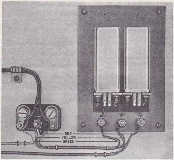

6 SECTION Fig A1A Protedor with 40BA Capacitor Installed Page 6 6 Pages


7 BELL SYSTEM PRACTICES Plant Series SECTION Issue 5, June 1970 AT&TCa Standard APPARATUS BLANKS IDENTIFICATION 1. GENERAL e111a apparatus blank 1.01 This section describes apparatus blanks and their use in station equipment This section is reissued to add information on: e94a apparatus blank e95c apparatus blank 2. IDENTIFICATION 2.01 Apparatus blanks are used to cover: eopening in nondial telephone. eopenings in booths, shelves, and plates. e Unequipped key spaces of , 656-, 657-, and 635-keys. e111b apparatus blank e50k apparatus blank 2.02 Apparatus blanks for telephones are available in the same colors as telephone sets. Add proper color code when ordering blanks. Fig Gray finished disc, 4-15/32 inches in diameter equipped with number card holder group and provided with connecting terminals. For 300- and 325-type outdoor telephone sets. FRONT REAR Fig. 2-85A-Black finished metal disc, 4-15/32 inches in diameter, equipped with number card holder group and connecting terminals. For 320-type explosion-proof telephone sets. FRONT REAR c Am< rican Telephone and Telegroph Company, 1971l Printed in U.S.A. Page 1

 i not provided with number card holder group. Replaces 82A.")
-Similar in frontnl appearance to the 95C (early model).")
8 SECTION FRONT REAR Fig. 3-94A-Piastic plate in all colors, 3-1/54 inches in diameter provided with connecting terminals and chrome plated number card holder group. 94A-3 (BK) i not provided with number card holder group. Replaces 82A. For 300-type indoor telephone sets. Fig. 4-95C (Current Modei)-Similar in frontnl appearance to the 95C (early model). Equipped with ribs which provide frictional fit to dial mounting bracket on sets having 2 and 3 point suspension. Page 2
 equipped with ribs which provides frictional fit to dial mounting bracket.")


9 ISS 5, SECTION Fig and 95C (Early Modei)-95C replaces 95B. 95C (early model) equipped with ribs which provides frictional fit to dial mounting bracket. It will fit only sets having 2 point suspension.t 95B provided with mounting bracket and screws. All apparatus blanks are provided with m.. mber card holder group. For 500-type telephone sets. Fig Molded opaque plastic blank used in unequipped 598- or 599-type key spaces. For 600-type telephone sets and key type consoles. Fig A-White plastic blank intended for use in the No. 3640A and 3641A type telephone sets to fill the space reserved for additional No. 635*2 (rectangular buttoned) keys. The width of the blank is the same as that of one of the keys Similar in appearance to llla and used in place of No. 635*5 (square buttoned) keys. *Any letter.t Page 3


10 SECTION tfig. 8-SOK-Metal mounting plate, 4-11/16 inches high by 4-3/4 inches wide. Equipped with a card frame, card holder assembly, Allen head mounting screws, and plastic window protector for the instruction card. Early production models will be provided with slot head mounting screws, and without the plastic window. The chrome plated 50K apparatus blank replaces the 501 apparatus blank. For all type coin collectors. Fig Black finished aluminum blank, 45/64-inch long by 112-inch in diameter. For plugging 1/2-inch wiring holes in telephone booths. Fig C-White finished aluminum blank, 51/64-inch long by 63/64-inch in diameter. For plug ing l-inch hole in ceiling of telephone booth. Fig C-White finished wooden blank, inch long by 1-7/64 inches in diameter. For plugging 1-1/ inch hole in ceiling of telephone booth. Page 4


11 ISS 5, SECTION Fig. 12-P Metal plate 7-3/8 inches long by 6-5/16 inches wide. For 10- and 11-type telephone booth when the KS blower is omitted. Fig. 13-KS-14611, List 45-Metal blank, 9-27/32 inches long by 1-7/8 inches high by 4 inches wide. For use in KS-14611, List 2 and List 3 outdoor booth directory racks when only one directory is placed. This blank can be installed only in the left compartment of a directory rack. Page 5


12 SECTION Fig Ciear anodized aluminum sheet with drawn edges, inches high by inches wide. For covering opening of 113-type apparatus box in absence of 750-type telephone set and 114-type apparatus box in absence of 752-type telephone sets. Provided with mounting brackets and screws. Fig A-Colored plastic plate; available in light olive gray ( 49), brown (-54), and ivory (-50). For covering unused opening in 16A faceplate. Page 6 6 Pas
RADIO SIGNAL SUPPRESSION FOR TELEPHONE SETS
 BELL SYSTEM PRACTICES Plant Series SECTION 500-150-1 00 Issue 6, April 1970 AT&TCo Standard RADIO SIGNAL SUPPRESSION FOR TELEPHONE SETS 1. GENERAL 1.01 This section contains information on the reduction
RADIO SIGNAL SUPPRESSION FOR TELEPHONE SETS
 BELLSYSTEM PRACTICES SECTION500-150-11X) AT&TCo Standard Issue 7, January 1974 RADIO SIGNAL SUPPRESSION FOR TELEPHONE SETS 1. GENERAL Transistors in amplifiers of some networks and handsets 1.01 This section
RADIO SIGNAL SUPPRESSION FOR TELEPHONE SETS IDENTIFICATION, INSTALLATION, AND MAINTENANCE
 AT & T PRACTICE Standard AT & T 500-150-100 Issue 11, July 1984 RADIO SIGNAL SUPPRESSION FOR TELEPHONE SETS IDENTIFICATION, INSTALLATION, AND MAINTENANCE 1. GENERAL 1.01 This practice contains information
1\. power 3A speakerphone systems.
 BELL SYSTEM PRACTICES AT&TCo Standard SECTION 501-136-100 Issue 5, May 1972 STATION TRANSFORMERS IDENTIFICATION 1. GENERAL 1.01 This section is reissued to: Include KS-20426L3 transformer Change Read,
KS TELETRAINER DESCRIPTION AND MAINTENANCE
 BELL SYSTEM PRACTICES AT&TCo Standard SECTION 473-411-100 Issue 4, January 1973 KS-16605 TELETRAINER DESCRIPTION AND MAINTENANCE 1. GENERAL 1.01 This section covers the description and maintenance of the
LBI-31564A. Mobile Communications. DELTA - SX MHz RADIO COMBINATIONS (NEGATIVE GROUND ONLY) Maintenance Manual
 Maintenance Manual") A Mobile Communications DELTA - SX 136-174 MHz RADIO COMBINATIONS (NEGATIVE GROUND ONLY) Maintenance Manual TABLE OF CONTENTS MILITARY AND SYSTEM SPECIFICATIONS................................. 2-3 COMBINATION
A Mobile Communications DELTA - SX 136-174 MHz RADIO COMBINATIONS (NEGATIVE GROUND ONLY) Maintenance Manual TABLE OF CONTENTS MILITARY AND SYSTEM SPECIFICATIONS................................. 2-3 COMBINATION
TELEPHONE SETS 701, 702, AND 711 TYPES INSTALLATION
 BELLSYSTEM PRACTICES SECTION 502-710-200 Plant Series Issue 3, January, 1963 AT&TCo Standard TELEPHONE SETS 701, 702, AND 711 TYPES INSTALLATION 1.00 INTRODUCTION 2.00 GENERAL 1.01 This section covers
23A TRANSMISSION MEASURING SET (J94023A) (DESCRIPTION)
 (DESCRIPTION)") BELL SYSTEM PRACTICES Central Office.Mainte>ance Description of Testing Equipment and Tools Toll Test Room Operation Description and Operating Principles of Systems and Equipment SECTION A702.625 Issue
BELL SYSTEM PRACTICES Central Office.Mainte>ance Description of Testing Equipment and Tools Toll Test Room Operation Description and Operating Principles of Systems and Equipment SECTION A702.625 Issue
MODEL CM-30. Technical Practice November 2002 Issue 4. Service Observing System 1. GENERAL 2. DESIGN FEATURES CONTENTS: Model CM-30
 Model CM-30 Technical Practice November 2002 Issue 4 MODEL CM-30 Service Observing System 1. GENERAL 1.01 The DEES CM-30 is a complete 30 line service observing system with integrated talk assist capability.
TT-07 TAP TRAP INSTRUCTION MANUAL TT-07 GENERAL INFORMATION
 Size: 5.5 x 2.75 x 1 Weight: 9 oz. Batteries: 9 volt transistor type. TT-07 TAP TRAP INSTRUCTION MANUAL TT-07 GENERAL INFORMATION The Tap Trap can detect both series and parallel wiretaps that are attached
Circuit Components Lesson 4 From: Emergency Management Ontario
 4.1 Amplifier Fundamentals The role of a amplifier is to produce an output which is an enlarged reproduction of the features of the signal fed into the input. The increase in signal by an amplifier is
PAT-4 POWER SUPPLY ASSEMBLY MANUAL Rev B Version
 PAT-4 POWER SUPPLY ASSEMBLY MANUAL Rev B Version 2013 AkitikA, LLC All rights reserved Revision Bp01 November 3, 2013 Page 1 of 16 Table of Contents Table of Contents... 2 Table of Figures... 2 Section
COMMON AUDIBLE SIGNALING KEY TELEPHONE SYSTEMS
 BELL SYSTEM PRACTICES AT & TCo Standard SECTION 518-0 1 0-1 08 Issue 3, October 1976 COMMON AUDIBLE SIGNALING KEY TELEPHONE SYSTEMS 1. GENERAL 1.01 This section provides a general description of common
ELECTRIC GROUNDING AND WIRING REQUIREMENTS BOOTHS-METAL
 BELL SYSTEM PRACTICES Plant Series SECTION 508-100-100 Issue 3, October 1970 AT&TCo Standard ELECTRIC GROUNDING AND WIRING REQUIREMENTS BOOTHS-METAL I. GENERAL 1.01 This section is reissued to: Revise
LBI-31807D. Mobile Communications MASTR II REPEATER CONTROL PANEL 19B234871P1. Maintenance Manual. Printed in U.S.A.
 D Mobile Communications MASTR II REPEATER CONTROL PANEL 19B234871P1 Maintenance Manual Printed in U.S.A. This page intentionally left blank 13 PARTS LIST 12 PARTS LIST LBI-31807 11 PARTS LIST 10 SCHEMATIC
Using Ferrite Beads Keep RF Out of TV Sets, Telephones, VCR's Burglar Alarms and other Electronic Equipment
 Using Ferrite Beads Keep RF Out of TV Sets, Telephones, VCR's Burglar Alarms and other Electronic Equipment RFI and TVI have been with us for a long time. Now we have microwave ovens, VCR's and many other
TECHNICAL MANUAL DIRECT SUPPORT, GENERAL SUPPORT, AND DEPOT MAINTENANCE MANUAL INCLUDING REPAIR PARTS AND SPECIAL TOOLS LISTS RADIO SET AN/PRC-47
 TECHNICAL MANUAL DIRECT SUPPORT, GENERAL SUPPORT, AND DEPOT MAINTENANCE MANUAL INCLUDING REPAIR PARTS AND SPECIAL TOOLS LISTS RADIO SET AN/PRC-47 This copy is a reprint which includes current pages from
Important Safety Information
 OWNER'S MANUAL Important Safety Information 1. Read these instructions. 2. Keep these instructions. 3. Heed all warnings. 4. Follow all instructions. 5. Do not use this apparatus near water. 6. Clean only
UNITED MOTORS SERVICE D IV ISIO N OF GENERAL M O TO RS C O R P O R A T IO N. General Offices - Detroit AUTO RADIO BULLETIN
 UNITED MOTORS SERVICE D IV ISIO N OF GENERAL M O TO RS C O R P O R A T IO N General Offices - Detroit AUTO RADIO BULLETIN Bulletin 6D-855 Date 11-1-54 Page 1 FIRST ISSUE SUBJECT: SERVICE INSTRUCTIONS -
Instructions MODIFICATION KIT MODEL SBM - 1O2-1 INTRODUCTION PARTS LIST FOR THE
 Instructions FOR THE MODIFICATION KIT MODEL SBM - 1O2-1 INTRODUCTION This modification Kit applies to the following Heath Transceivers: 1. All Models HW-100, SB-100, SB-101 and SB-101W. 2. Any Model SB-102
r--- INSIDE WIRE CABLE
 Scanned b Frank Harrell, (Cowbo Frank) Castle Rock, Colorado Oct 09, 01 14:6 :"ol. BELL SYSTEM PRACTICES Plant Series SECTION 461-60-1 00 Issue 1, January 1968 AT&TCo Standard CONNECTING BLOCKS 4A, 44A,
SERVICE SPECIAL SAFEGUARD MEASURES SPECIAL SERVICE PROTECTION RADIO AND TELEGRAPH LOOPS
 BELL SYSTEM PRACTCES Plant Series SECN 460-11 0-400 ssue 1, December 1969 AT & TCo Standard SERVCE SPECAL SAFEGUARD MEASURES SPECAL SERVCE PROTECN RADO AND TELEGRAPH LOOPS 1. GENERA L 1.01 This section
D ELCO. electronic parts AUTO RADIO BULLETIN. Connect Signal Generator to
 D ELCO electronic parts AUTO RADIO BULLETIN Bulletin 6D-864 Date 10-15-56 Page 1 FIRST ISSUE SUBJECT: SERVICE INSTRUCTIONS - CHEVROLET CUSTOM DELUXE WITH PUSH BUTTON TUNING - MODEL 987575 GENERAL M O U
INCOMING SELECTOR CIRCUITS FROM PANEL LOCAL, OFFICE TANDEM AND PANEL SENDER TANDEM OFFICES MANUAL TEST USING TEST SET ES OR ES
 BELL SYSTEM PRACTICES Plant Series INCOMING SELECTOR CIRCUITS FROM PANEL LOCAL, OFFICE TANDEM AND PANEL SENDER TANDEM OFFICES MANUAL TEST USING TEST SET ES-20150-01 OR ES-239844,,, I' I Issue 3, November,
Building the Sawdust Regenerative Receiver
 Building the Sawdust Regenerative Receiver Introduction The Sawdust is a super regenerative receiver using the basic Armstrong design architecture. The receiver uses one toroidal transformer to provide
Time of Arrival Radio Direction Finder.
 Time of Arrival Radio Direction Finder. Time of arrival (TOA) RDF units are simple and very useful. Various designs have been distributed over the years, and here is another one. This Kit Developed by
E L E C R A F T K N B 1 N O I S E B L A N K E R
 Introduction E L E C R A F T K N B N O I S E B L A N K E R Assembly and Operating Instructions Revision C, Jan. 8, 200. Copyright 200, Elecraft; All Rights Reserved The KNB noise blanker can be used to
REFERENCE 1 A 1 KEY TELEPHONE SYSTEM. "TOUCH-TONE n ADAPTERS
 BELL SYSTEM PRACTICES AT&TCo Standard Issue 2, September 1971 REFERENCE 1 A 1 KEY TELEPHONE SYSTEM "TOUCH-TONE n ADAPTERS 1. GENERAL 1.01 This section is reissued to change relay designation H3 to L3 for
Line-Following Robot
 1 Line-Following Robot Printed Circuit Board Assembly Jeffrey La Favre October 5, 2014 After you have learned to solder, you are ready to start the assembly of your robot. The assembly will be divided
UNITED MOTORS SERVICE. DIVISION OF GENERAL MOTORS CORPORATION General Offices - Detroit AUTO RADIO BULLETIN
 UNITED MOTORS SERVICE DIVISION OF GENERAL MOTORS CORPORATION General Offices - Detroit AUTO RADIO BULLETIN Bulletin 6D-848 Chevrolet 986515 Page 1 SUBJECT: SERVICE INSTRUCTIONS CHEVROLET CUSTOM DELUXE
BELLSYSTEM PRACTICES SECTION AT&TCo Standard Issue 7, November 1979 IDENTIFICATION
 BELLSYSTEM PRACTICES SECTION 501-136-100 AT&TCo Standard Issue 7, November 1979 STATION TRANSFORMERS IDENTIFICATION 1 GENERAL unit to be in close proximity to the ac line source is not recommended. 1.01
7A COMMUNICATION SYSTEM"-COM KEY*"718 KEY TELEPHONE SYSTEM DESCRIPTION, ORDERING INFORMATION, AND OPERATION
 BEU SYSTEM PRACTICES AT&TCo Standard SECTION 518-450-1 00 Issue S, February 1982 7A COMMUNICATION SYSTEM"-COM KEY*"718 KEY TELEPHONE SYSTEM DESCRIPTION, ORDERING INFORMATION, AND OPERATION CONTENTS PAGE
AM Generation High Level Low Level
 AM Generation High Level Low Level Low-level generation In modern radio systems, modulated signals are generated via digital signal processing (DSP). With DSP many types of AM modulation are possible with
CHAPTER 3 PROJECT METHODOLOGY
 CHAPTER 3 PROJECT METHODOLOGY 3.1 Introduction This chapter will cover the details explanation of methodology that is being used to make this project complete and working well. Many methodology or findings
SoftRock v6.0 Builder s Notes. May 22, 2006
 SoftRock v6.0 Builder s Notes May 22, 2006 Be sure to use a grounded tip soldering iron in building the v6.0 SoftRock circuit board. The soldering iron needs to have a small tip, (0.05-0.1 inch diameter),
LBI-30398N. MAINTENANCE MANUAL MHz PHASE LOCK LOOP EXCITER 19D423249G1 & G2 DESCRIPTION TABLE OF CONTENTS. Page. DESCRIPTION...
 MAINTENANCE MANUAL 138-174 MHz PHASE LOCK LOOP EXCITER 19D423249G1 & G2 LBI-30398N TABLE OF CONTENTS DESCRIPTION...Front Cover CIRCUIT ANALYSIS... 1 MODIFICATION INSTRUCTIONS... 4 PARTS LIST AND PRODUCTION
Assembly and Installation Instructions for White Oak Audio Design PL400 Series 1 LED board
 Thank you for purchasing White Oak Audio Design s Phase Linear PL400 Upgrade LED Light Board. White Oak Audio Design products are meticulously engineered and tested to ensure a direct drop in fit with
LBI-4938C. Mobile Communications MASTR II POWER AMPLIFIER MODELS 4EF4A1,2,3. Printed in U.S.A. Maintenance Manual
 C Mobile Communications MASTR II POWER AMPLIFIER MODELS 4EF4A1,2,3 Printed in U.S.A. Maintenance Manual TABLE OF CONTENTS DESCRIPTION.................................................... 1 CIRCUIT ANALYSIS.................................................
Maintenance Manual CHANNEL GUARD ENCODER/DECODER 19D430740G1 TONE REJECT FILTER 19D430740G4. Mobile Communications
 E ********* (REPLACES LBI-4143) Mobile Communications CHANNEL GUARD ENCODER/DECODER 19D430740G1 TONE REJECT FILTER 19D430740G4 Printed in U.S.A. Maintenance Manual TABLE OF CONTENTS SPECIFICATIONS..................................................
ERICSSONZ LBI-30398P. MAINTENANCE MANUAL MHz PHASE LOCKED LOOP EXCITER 19D423249G1 & G2 DESCRIPTION TABLE OF CONTENTS
 MAINTENANCE MANUAL 138-174 MHz PHASE LOCKED LOOP EXCITER 19D423249G1 & G2 TABLE OF CONTENTS Page DESCRIPTION... Front Cover CIRCUIT ANALYSIS...1 MODIFICATION INSTRUCTIONS...4 PARTS LIST...5 PRODUCTION
HAMTRONICS TB901 FM EXCITER INSTALLATION, OPERATION, & MAINTENANCE
 HAMTRONICS TB901 FM EXCITER INSTALLATION, OPERATION, & MAINTENANCE GENERAL INFORMATION. The TB901 is a single-channel low power fm transmitter (exciter) designed to provide 300-600 milliwatts continuous
4A SPEAKERPHONE COMPONENTS. IDENTIFICA lion, INST ALLA lion, OPERA lion, AND MAINTENANCE
 BELL SYSTEM PRACTICES AT& TCo Standard SECTION 512-700-100 Issue 5, April 1979 4A SPEAKERPHONE COMPONENTS IDENTIFICA lion, INST ALLA lion, OPERA lion, AND MAINTENANCE 1. GENERAL 1.01 This section contains
V-136RTHF 36 ZONE TALKBACK INTERCOM/ PAGE CONTROL UNIT
 VSP-V-13RTHF Issue V-13RTHF 3 ZONE TALKBACK INTERCOM/ PAGE CONTROL UNIT GENERAL The V-13RTHF is a single-path dial select microcomputer controlled intercom and page control unit used with a 1A2 key system
Radio Station Setup and Electrical Principles
 Radio Station Setup and Electrical Principles Covers sections: T4A-T5D Seth Price, N3MRA February 20, 2016 Outline 4.1 Station Setup 4.2 Operating Controls 4.3 Electronic Principles 4.4 Ohm s Law 4.5 Power
Building the Toothpick Audio CW Filter
 Building the Toothpick Audio CW Filter Introduction The toothpick is a simple variable bandpass audio filter designed to compliment the Splinter QRPp Trans-Receiver. The filter also contains an audio amplifier
LED Field Strength Indicator Kit
 LED Field Strength Indicator Kit Description The Field Strength Indicator kit from Qrpkits.com provides a visual way to monitor RF fields through the brightness of an LED. It will respond to RF fields
Lighthouse Beginner s soldering kit
 Lighthouse Beginner s soldering kit Kit contains: 1 x 220 ohm resistor (Red, Red, Black) 1 x 82k ohm resistor (Grey, Red, Orange) 2 x 220k ohm resistors (Red, Red, Yellow) 2 x Diodes 1 x Power switch 1
TELEPHONE BUG KIT MODEL K-35. Assembly and Instruction Manual
 TELEPHONE BUG KIT MODEL K-35 Assembly and Instruction Manual Elenco Electronics, Inc. Copyright 2010, 1989 by Elenco Electronics, Inc. All rights reserved. Revised 2010 REV-L 753235 No part of this book
LDB-1 Kit Instructions Page 1 of 8
 LDB-1 Kit Instructions Page 1 of 8 Important Information Congratulations and thank you for your purchase of the LDB-1 Little Drummer Boy Analog Drum Machine Kit! Before you start, please read the enclosed
CABLE TRACER & PHONE TESTER / GENERATOR
 CABLE TRACER & PHONE TESTER / GENERATOR 183 CB-A Amplifier Probe INSTRUCTION MANUAL Amplifier Probe Amplifier Probe 183 CB-A Figure 1 Amplifier Probe 183 CB-A Figure 2 Features The Amplifier Probe is designed
Assembly and Installation Instructions for White Oak Audio Design TM-1001 LED board
 Thank you for purchasing White Oak Audio Design s TM-1001 Upgrade LED Light Board. White Oak Audio Design products are meticulously engineered and tested to ensure a direct drop in fit with your tuner.
HW-8-TR V3 PARTS LIST
 HW-8-TR V3 PARTS LIST Qty Ref Description Markings 4C2 C3 C4 C5 Capacitor Disc.1ls.1uF 104 1 C1 Capacitor Disc.2ls.1uF 100V 104 1 QSKMOD-C92 Capacitor Electrolytic 1uF 50V 1 QSKMOD Capacitor Mylar.47uF
3. Assembly manual ANALYZING THE PCB'S LCD PCB. Component side: Solder side:
 3. Assembly manual ANALYZING THE PCB'S LCD PCB Component side: Solder side: MAIN PCB Component side: Solder side: ASSEMBLGING THE LCD PCB 1. Resistor R1: 33 Ohm (orange, black, black) 2. 6 Pin female header
Assembly and Operating Instructions. Revision D, Aug. 20, Copyright 2002, Elecraft; All Rights Reserved
 Introduction E L E C R A F T K N B N O I S E B L A N K E R Assembly and Operating Instructions Revision D, Aug. 0, 00. Copyright 00, Elecraft; All Rights Reserved The KNB noise blanker can be used to suppress
Assembly Manual for VFO Board 2 August 2018
 Assembly Manual for VFO Board 2 August 2018 Parts list (Preliminary) Arduino 1 Arduino Pre-programmed 1 Faceplate Assorted Header Pins Full Board Rev A 10 104 capacitors 1 Rotary encode with switch 1 5-volt
Easy Transmitter. Support ETX_REV5_Manual V2.7 Revised
 Easy Transmitter Introduction The Easy Transmitter kit from qrpkits.com provides a basic, crystal controlled transmitter with VXO tuning to provide a small tuning range around the crystal frequency. It
Building the Sawdust Regenerative Receiver
 Building the Sawdust Regenerative Receiver Introduction The Sawdust is a super regenerative receiver using the basic Armstrong design architecture. The receiver uses one toroidal transformer to provide
Assembly Manual V1R2B-Rev1.0D
 Assembly Manual V1R2B-Rev1.0D for 4 State QRP MagicBox - Solid State Transmit/Receive System Designed by: Jim Kortge, K8IQY Copyright 2009-2012 - All rights reserved This system is the result of some brainstorming
SoftRock v6.0 Builder s Notes. April 6, 2006
 SoftRock v6.0 Builder s Notes April 6, 006 Be sure to use a grounded tip soldering iron in building the v6.0 SoftRock circuit board. The soldering iron needs to have a small tip, (0.05-0. inch diameter),
NOTE: The relay coil is polarity sensitive
 External QSK T/R Switch for HF Amplifiers Phil Salas AD5X Like many HF amplifiers, my Ameritron ALS-600 uses a power relay for T/R switching. The long 15-20ms enable/release time of this relay makes the
Read This Page First
 Read This Page First If you are reading this you know the manuals are always available at QRPKITS.com. This is version 8.0 of the manual dated 4/27/2016. There is no need to print out the whole assembly
TCI Library-
 Section L of TELEPHONE EQUIPMENT & SUPPLIES CATALOG ISSUED SEPTEMBER, 1966 RECORDERS & ANNOUNCERS Recorder,-Announcers Type INT, Single-Channel, Fixed Message Length, Compact Transistorized Recorder-Announcers;
Call/Talk. GAI-Tronics Call/Talk communication systems. GAI-TRONICS A Hubbell Company
 GAI-TRONICS A Hubbell Company Call/Talk GAI-Tronics Call/Talk communication systems provide paging and party-line capabilities in a durable, easy-to-operate package. Plant personnel use the paging capability
Beta-test ED1 PCB installed in I0CG s K1
 K1 SSB Modification (Ed.2) This description provides the receiver (RX) modifications, assembly, alignment and operation as a first step. In a second step you can add the remaining transmitter (TX) modifications,
W2IHY PASSIVE FIXED OR VARIABLE ATTENUATOR KIT
 W2IHY PASSIVE FIXED OR VARIABLE ATTENUATOR KIT C Copyright 11/14/02 W2IHY TECHNOLOGIES The W2IHY Passive Fixed / Variable Attenuator is designed to be a versatile accessory that is a necessity for the
MINI FM PHONE TRANSMITTER KIT
 MINI FM PHONE TRANSMITTER KIT Description: This is a subminiature FM telephone transmitter capable of transmitting both sides of a telephone conversation to most any FM receiver up to 1/4 mile away. When
1825 Duet Plus Installation Guide
 1825 Duet Plus Installation Guide Algo Communication Products Ltd. www.algosolutions.com 90-00046B - 1 - Table of Contents Release 2 Updates - Feb. 2012... 3 Quick Install for Dry Contact Ringing... 4
Assembly Instructions for the 1.5 Watt Amplifier Kit
 Assembly Instructions for the 1.5 Watt Amplifier Kit 1.) All of the small parts are attached to a sheet of paper indicating both their value and id. 2.) Leave the parts affixed to the paper until you are
900 MHz Digital Wireless Indoor/Outdoor Speakers
 4015007 900 MHz Digital Wireless Indoor/Outdoor Speakers User s Manual This 900 MHz digital hybrid wireless speaker system uses the latest wireless technology that enables you to enjoy music and TV sound
TH Place, Maspeth, NY Instruction Manual for UNO Exit Signs
 57-10 49 TH Place, Maspeth, NY 11378 Instruction Manual for UNO Exit Signs 1. What is included in this box? Back box with electronics, battery (where applicable), & mounting hardware. Inner trim, LED illuminator
1 FUNCTIONAL DESCRIPTION WAY SPLITTER/INPUT BOARD FET RF AMPLIFIERS WAY POWER COMBINER VSWR CONTROL BOARD...
 CONTENTS 1 FUNCTIONAL DESCRIPTION...1 2 4-WAY SPLITTER/INPUT BOARD...2 3 FET RF AMPLIFIERS...3 4 4-WAY POWER COMBINER...4 5 VSWR CONTROL BOARD...5 6 ADJUSTMENT OF BIAS VOLTAGE TO ESTABLISH PROPER QUIESCENT
GC-1032 Metal Detector OWNER S MANUAL
 GC-1032 Metal Detector OWNER S MANUAL 1 With your GC-1032 metal detector, you can hunt for coins, relics, jewelry, gold, and silver just about anywhere. The detector comes with high sensitivity and strong
RCA Radiola 60 REG. U.S. PAT. OFF.
 RCA Radiola 60 REG. U.S. PAT. OFF. Super-Heterodyne AC Socket-Powered Instructions IB-60-1 Radio Corporation of America 233 Broadway New York City 100 West Monroe Street 235 Montgomery Street Chicago,
Read This Page First
 Read This Page First If you are reading this you know the manuals are always available at QRPKITS.com. If you have questions contact qrpkits.com@gmail.com There is no need to print out the whole assembly
PM24 Installation Instructions
 Marchand Electronics Inc. PO Box 473, Webster, NY 14580 Tel:(716) 872-0980 Fax:(716) 872-1960 info@marchandelec.com http://www.marchandelec.com (c)1997 Marchand Electronics Inc. PM24 Installation Instructions
RadiØKit Μ CW HAM RADIO TRANSCEIVER KIT. Assembly and operating manual
 RadiØKit-120 20Μ CW HAM RADIO TRANSCEIVER KIT Assembly and operating manual Boreiou Ipirou 78 Kolonos Athens- Greece - 10444 Tel: 210.5150527 210.5132673 www.freebytes.com Thank you for buying RadiØKit-1,
IC-781: Installing the Inrad Roofing Filter Mod
 IC-781: Installing the Inrad Roofing Filter Mod The Icom IC-781 roofing filter mod consists of a 6-pole, 4 to 5 khz wide filter followed by a high dynamic range, feedback amplifier. The amplifier provides
S5-ADU. Front... 4 Rear... 4
 Trantec ANTENNA DISTRIBUTOR INSTRUCTION MANUAL S5-ADU Thank you for purchasing TRANTEC Antenna Distributor. Please carefully follow the instructions in this manual to ensure long, trouble-free use of your
English KS-DR3005D POWER AMPLIFIER: INSTRUCTION MANUAL
 KS-DR005D POWER AMPLIFIER: INSTRUCTION MANUAL B5E-009-00/00 [W] WARNING If the fuse blows, first make sure the wires aren t touching to cause a short circuit then replace the old fuse with one with the
EXPERIMENT #2 CARRIER OSCILLATOR
 EXPERIMENT #2 CARRIER OSCILLATOR INTRODUCTION: The oscillator is usually the first stage of any transmitter. Its job is to create a radio-frequency carrier that can be amplified and modulated before being
Installation... 3 Installing The Radio... 3 Ignition Noise Interference... 4 Antenna... 4 External Speaker... 4 Public Address...
 TABLE OF CONTENTS CHAPTER 1 Specifications.............................................. 2 PAGE BIG RIG SERIES S 1 MOD PW R 20 0 3 SW R 40 1 5 5 60 1.5 7 10 2 9 20 80 3 30 +20 40 50 +40 100% MAX db +60
Station Guide. Pro700 Communication System. Pro700 Installation and Programming Manual A100K10226/04.00 Jul. 2006
 1 Updated July 22 2011 Communication System Installation and Programming Manual A100K10226/04.00 Jul. 2006 2 Table of Contents 1 GENERAL SYSTEM DESCRIPTION... 4 1.1 Typical System Users... 4 1.2 Keypad
BELL SYSTEM PRACTICES Plant Series
 BELL SYSTEM PRACTCES Plant Series SECTON 58469MS ssue B, August, 963 M. S. T. & T. Co. CON COLLECTOR TELECART dentification, nstallation and Maintenance. DENTFCATON. The Coin Collector Telecart consists
TWS 16 HT UHF wireless system. user manual
 TWS 16 HT UHF wireless system user manual Musikhaus Thomann e.k. Treppendorf 30 96138 Burgebrach Germany Telephone: +49 (0) 9546 9223-66 E-mail: info@thomann.de Internet: www.thomann.de 30.04.2012 Table
KWM Quartet Wireless microphone system
 KWM Quartet Wireless microphone system M A N U A L V E R S I O N 2. 0 2 4-1 1-1 4 Professional UHF wireless system with 4 x USB rechargeable handheld microphones Due to continuous product development,
Simple LFO Features. 2. Application. 3. Description. Simple and easy to build LFO module for Analog Synthesizers.
 Simple LFO. Simple and easy to build LFO module for Analog Synthesizers.. Features Square and Triangle waveforms (90 phase shifted) Dual range frequencies Frequency ranges from under Hz up to several khz
Schooners II. Weatherproof Wireless 900MHz Speaker System. User Guide. Model no.: GDI-AQSHR200 / AQSHR21
 Schooners II Weatherproof Wireless 900MHz Speaker System User Guide Model no.: GDI-AQSHR200 / AQSHR21 IMPORTANT: Please read your User s Guide before using your system INTRODUCTION Your SCHOONERS II speaker
HT-1A Dual Band CW QRP Transceiver. Kit Building Instructions
 HT-A Dual Band CW QRP Transceiver Kit Building Instructions Rev B, July 8, 08 Designed by BD4RG Exclusively distributed by CRKITS.COM and its worldwide distributors Join the group http://groups.io/g/crkits
Introduction 1. Download socket (the cable plugs in here so that the GENIE microcontroller can talk to the computer)
") Introduction 1 Welcome to the magical world of GENIE! The project board is ideal when you want to add intelligence to other design or electronics projects. Simply wire up your inputs and outputs and away
Introduction 1 Welcome to the magical world of GENIE! The project board is ideal when you want to add intelligence to other design or electronics projects. Simply wire up your inputs and outputs and away
ADA416-XLR DISTRIBUTION AMPLIFIERS OPERATING AND MAINTENANCE MANUAL
 ADA416-XLR DISTRIBUTION AMPLIFIERS OPERATING AND MAINTENANCE MANUAL Copyright 2015, ATI Audio Inc. DESCRIPTION Your ADA416-XLR provides four independent one-in by four-out circuit groups. A four-output
DIGITAL MULTIMETER CONTENTS DIGITAL MULTIMETER CONTENTS
 CONTENTS CONTENTS CONTENTS 1. SAFETY INFORMATION...1 1.1 Preliminary...1 1.2 Dos and don ts...2 1.3 Symbols...3 1.4 Precautions...4 2. DESCRIPTION...5 2.1 Names of parts...6 2.2 Switches, buttons and input
Hendricks QRP Kits The Twofer Rev
 Hendricks QRP Kits The Twofer Rev 1 11-15-06 1. Description The Twofer is a classic QRP transmitter that s easy to assemble and operate. It uses a JFET VXO (variable crystal oscillator), driver stage and
Find a place where you can work through completion, without disturbing your
 Scan by Manual Manor ARIES SYSTEM 300 MUSIC SYNTHESIZER Page I of 4 MODULE AR-334 SEQUENCER ASSEMBLY INSTRUCTIONS It is recommended that you do the following before you proceed: Find a place where you
Ten Tec DDS Board Assembly Procedure
 05 May 2014 Ten Tec DDS Board Assembly Procedure You will find a photo of a completed board at the end of these instructions. Refer it whenever clarification is required. 1. AD9835 Attachment If you purchased
Read This Page First
 Pacific Antenna 0 Watt HF Amplifier Kit Manual This is Version 5.5 dated 060505 Read This Page First If you are reading this you know the manuals are always available at QRPKITS.com. If you have questions
900MHz Digital Hybrid Wireless Outdoor Speakers
 4015004 900MHz Digital Hybrid Wireless Outdoor Speakers User s Manual This 900 MHz digital hybrid wireless speaker system uses the latest wireless technology that enables you to enjoy music and TV sound
ASSEMBLY MANUAL FOR R3500D DIRECTION FINDING RECEIVER KIT
 SDR-Kits www.sdr-kits.net SDR-Kits is CRKITS Authorised Distributor for Europe ASSEMBLY MANUAL FOR R3500D DIRECTION FINDING RECEIVER KIT Rev. A May 24, 2015 Written by CRKITS http://www.crkits.com Thanks
KN-Q10 Assembly Manual
 KN-Q10 Assembly Manual Translated by Adam Rong, BD6CR/4 with permission from Ke Shi, BA6BF Edited by Stephen, VK2RH Revision B, Oct 14, 2010 Thank you for purchasing the KN-Q10 4 Band SSB/CW Dual Mode
A 100-Watt Transmitter Using a Pair of VT1625s
 12/16/2007 6:00 PM VT1625 100 Watt Transmitter A 100-Watt Transmitter Using a Pair of VT1625s FIG. 10.6 A 100-watt transmitter for five bands, using salvaged TV power transformer and surplus 1625 amplifier
Power Supply. Note: you can t charge the standard battery or rechargeable battery via Mains operation. 2
 MMR-77 GB Version 1 1 1 2 3 4 5 6 7 8 9 Controls AM/FM band switch Emergency buzzer Dynamo power AM/FM band indicator Tuning LED indicator Charging LED indicator Illumination button Dial scale Dial pointer