Power Supply and automatic Voltage
|
|
|
- Cuthbert Chandler
- 6 years ago
- Views:
Transcription

1 Power Supply and automatic Voltage Control
2 ESP Controls Understanding ESP Controls
3 Power Supply System The power supply system is designed to provide voltage to the electrical field (or bus section) at the highest possible level. The voltage must be controlled to avoid causing sustained arcing or sparking between the electrodes and the collecting plates. Precipitator power system animated schematic showing representative components. When electrical fields are in series, the power supply for each field can be adjusted to optimize operation of that field. Likewise, having more than one electrical bus section in parallel allows adjustments to compensate for their differences, so that power input can be optimized. Donnerstag, 12. September 2013 Fußzeilentext 3
4 Components The power supply system has four basic components: Automatic voltage control Step-up transformer High-voltage rectifier Sensing device Voltage control Donnerstag, 12. September 2013 Fußzeilentext 4
5 AVC Automatic voltage control a. varies the power to the transformer-rectifier b. in response to signals received from sensors in the precipitator and the transformer-rectifier itself. c. monitors the electrical conditions inside the precipitator, d. protects the internal components from arc-over damages, and e. protects the transformer-rectifier and other components in the primary circuit. Donnerstag, 12. September 2013 Fußzeilentext 5
6 AVC Contd. The ideal automatic voltage control would produce a. maximum collecting efficiency by holding the operating voltage of the precipitator at a level just below the spark-over voltage. b. this level cannot be achieved given that conditions change from moment to moment. c. Instead, the automatic voltage control increases output from the transformer-rectifier until a spark occurs. d. Then the control resets to a lower power level, and the power increases again until the next spark occurs. Donnerstag, 12. September 2013 Fußzeilentext 6
7 Automatic Voltage Controllers (for Electrostatic Precipitators) An electronic device used to control the application of D.C. power into a field of an electrostatic precipitator. Functions: Optimize power application:- to deliver as much useful electrical power to the corresponding field(s) as possible. Spark reaction When the voltage applied to the field is too high for the conditions at the time, a spark over (or corona discharge) will occur. Detrimentally high amounts of current can occur during a spark over if not properly controlled, which could damage the fields. A voltage controller will monitor the primary and secondary voltage and current of the circuit, and detect a spark over condition. Once detected, the power applied to the field will be immediately cut off or reduced, which will stop the spark. 7
8 After a short amount of time the power will be ramped back up, and the process will start over. Protect system components by adhering to component limitations The Transformer Rectifier set (TR set) can be damaged by excessive amounts of current or voltage flowing through it. Each TR set has voltage and current limits established by the manufacturer, which are labeled on an attached nameplate. These nameplate limit values (typically primary and secondary current, and voltage) are programmed into the voltage controller. Tripping When a condition occurs that the voltage controller cannot control, often times the voltage controller will trip. A trip means the voltage controller (by way of the contactor) will shut off the individual precipitator power circuit. A short inside the electrostatic precipitator field caused by a fallen discharge electrode (wire), or a shorted out Silicone Controlled Rectifier are examples of conditions that a voltage controller cannot control. Donnerstag, 12. September 2013 Fußzeilentext 8

9 Efficiency vs. Specific Corona Power
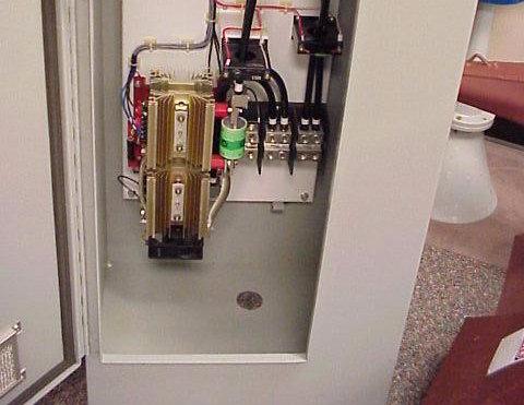
10 AVC Cabinet, CLR & T/R Set

11 Typical SCR-CLR Electrical System

12 Typical SCR-CLR Electrical System

13 How to Tell The Difference? Iron Vane Movement D Arsonval Average RMS The Meter Scale Distance is not the Same on the RMS Meter

14 Primary Current Meter


15 Finding the Primary Current Waveform
16 Primary Current A Chopped Sine Wave
17 Primary Current Waveform - Positive and Negative Half-Cycles = SCR 1 and SCR 2
18 Secondary Current Meter


19 Finding the ma Signal
20 Secondary Current Pulsating DC
21 Typical Primary and Secondary current

22 Secondary Voltage Meter
23 Current Limit -ma& KV
24 Secondary Voltage Waveforms True Negative


25 Next The Automatic Voltage Control
26 The Automatic Voltage Control The AVC is the BRAIN of the ESP


27 Older Analog AVC


28 Microprocessor Based AVC
29 The AVC has 2 Jobs to Execute Control the amount of sparking in the ESP. If a T/R set is not sparking, then its AVC should be pushing that T/R set to one of its pre-set, healthy limits (volts, amps, KV, ma, or firing angle).
30 The AVC feedback? But how does the AVC know what s happening in the ESP?


31 The masignal is its eyes! Transformer Rectifier Set
32 AVC Cabinet, CLR & T/R Set
33 AVC Spark Response
34 Good Initial Settings for an AVC 1.Quench = 1 Full Cycle 2. Fast Ramp = 5 or 6 Half Cycles 3. Setback = 15 to 20% 4. Spark Rate = 30SPM
35 Proper AVC Response to Sparking
36 Spark Response - Secondary Current Waveform
37 Spark Response - Secondary Current and Voltage Waveforms
38 Typical Spark Response -ma& KV
39 Further Control A Search Ramp Rate
40 Spit Spark Response (ma)ramp Rate
41 Spit Spark Response - Secondary Current and Voltage Waveforms
42 Examples of AVC s at a Limit


43 AVC SPARK LIMITED DOING IT S JOB


44 T/R Current Limited with Sparking


45 T-R CURRENT LIMITED WITHOUT SPARKING


46 T-R VOLTAGE LIMITED WITH SPARKING
47 What is meant by Healthy Limits? Primary or Secondary Limit is not healthy when accompanied by a Primary Voltage level< 90 VAC or a Secondary level < 12KV. It usually indicates a short circuit. Secondary Voltage Limit is not healthy when there is very little Secondary Current. It usually indicates an open circuit. Neither condition is aiding in particle capture

48 The T-R Set


49 Transformer Rectifier (T/R) Set


50 Inside T/R Tank


51 High Voltage Transformer


52 Diode Stack


53 T/R Set -Low Voltage Junction Box


54 Low Voltage Junction Box


55 T/R Nameplate

56 The KV Meter
57 Voltage Divider

58 SCR S

59 SCR
60 Typical Sine Wave
61 SCR: Low Voltage to T-R Set


62 SCR: High Power to T-R Set

63 The CLR

")
64 Current Limiting Reactor (CLR)


65 Current Limiting Reactor


66 Current Limiting Reactor at T-R Set


67 SCR s are why CLR s are Needed

68 Electrical Basics: CLR
69 CLR Function Limit short circuit current Shape T/R secondary wave to be more Sinusoidal Provide proper form factor Protect SCRs and T/R diodes from steep current rise Increase precipitator voltage and current Not to be confused with air core reactor
70 CLR Waveform Changes with Impedance

71 Proper CLR Sizes for Common T/R Sets


72 Basic Troubleshooting


73 TR Nameplate Values (For this exercise)


74
75 Close Clearance

76 Conductive Dust, Outlet Field

77 Bad KV Return
78 Open
79 Normal Running Condition

80 SCRs Not Firing


81 Thank You.
Duke Energy Seminar September 3 5, 2008 Concord, NC
 Duke Energy Seminar September 3 5, 2008 Concord, NC An Introduction to Precipitator Controls Systems The aim of this presentation is to: Identify the global requirement of an ESP Control System Identify
W P C A. Worldwide Pollution Control Association. WPCA-Duke Energy. Aug. 28, 2012 Plainfield Sept. 11, Charlotte
 Worldwide Pollution Control Association WPCA-Duke Energy Is Your Precipitator Ready for MATS? Aug. 28, 2012 Plainfield Sept. 11, 2012 - Charlotte All presentations posted on this website are copyrighted
REDKOH INDUSTRIES SWITCH MODE POWER SUPPLY DEMO UNIT
 Installation Guide REDKOH INDUSTRIES SWITCH MODE POWER SUPPLY DEMO UNIT These Demo Units are typically available for 30 day loans. Redkoh Requests that the customer pays the freight of the unit to and
WPCA AMEREN ESP. SEMINAR Understanding ESP Controls. By John Knapik. 2004, General Electric Company
 WPCA AMEREN ESP SEMINAR Undrstanding ESP Controls By John Knapik 2004, Gnral Elctric Company Efficincy vs. Spcific Corona Powr KNOW WHERE YOUR ESP RUNS ON THE CURVE 99.9 99.0 Collction Efficincy (Prcnt)
Redkoh Industries RK2000. Microprocessor Transformer Rectifier Control for Electrostatic Precipitators V1.40
 Redkoh Industries RK2000 Microprocessor Transformer Rectifier Control for Electrostatic Precipitators V1.40 Redkoh Industries 2009 TABLE OF CONTENTS INTRODUCTION: Maximum Flexibility with Minimum Emissions
Application of High-Voltage Power Supply on Electrostatic Precipitator
 World Journal of Engineering and Technology, 2017, 5, 269-274 http://www.scirp.org/journal/wjet ISSN Online: 2331-4249 ISSN Print: 2331-4222 Application of High-Voltage Power Supply on Electrostatic Precipitator
Particulate Control O&M Training. APC/PCUG Conference July 12-16, 2009 The Woodlands, TX
 Particulate Control O&M Training APC/PCUG Conference July 12-16, 2009 The Woodlands, TX WPCA Particulate Training Seminar July 11, 2009 ESP Power Supply Choices Slide No 1 Precipitator Power Supplies Conventional
Drives 101 Lesson 3. Parts of a Variable Frequency Drive (VFD)
") Drives 101 Lesson 3 Parts of a Variable Frequency Drive (VFD) This lesson covers the parts that make up the Variable Frequency Drive (VFD) and describes the basic operation of each part. Here is the basics
Drives 101 Lesson 3 Parts of a Variable Frequency Drive (VFD) This lesson covers the parts that make up the Variable Frequency Drive (VFD) and describes the basic operation of each part. Here is the basics
High frequency operated DC power source for electrostatic precipitators
 AR-70/1000 V.01 ESP power controller High frequency operated DC power source for electrostatic precipitators Why using high frequency instead of 50Hz SCR power AR-70/1000 product: Basic functionality and
Development of Measuring and Computer Interface System for an Industrial Electrostatic Precipitator
 Helwan University From the SelectedWorks of Omar H. Abdalla April, 2007 Development of Measuring and Computer Interface System for an Industrial Electrostatic Precipitator Omar H. Abdalla Soliman M. Sharaf
Power Electrician Level 3
 s Power Electrician Level 3 Rev. September 2008 Power Electrician Unit: C1 Electrical Code III Level: Three Duration: 60 hours Theory: Practical: 60 hours 0 hours Overview: This unit of instruction is
HIGH VOLTAGE ENGINEERING(FEEE6402) LECTURER-24
 LECTURER-24") LECTURER-24 GENERATION OF HIGH ALTERNATING VOLTAGES When test voltage requirements are less than about 300kV, a single transformer can be used for test purposes. The impedance of the transformer should
LECTURER-24 GENERATION OF HIGH ALTERNATING VOLTAGES When test voltage requirements are less than about 300kV, a single transformer can be used for test purposes. The impedance of the transformer should
Microprocessor Control Board Set Up Procedures (OR PLC)
") Microprocessor Control Board Set Up Procedures (OR-00 PLC) SWITCHES/PUSHBUTTONS Push Buttons at display SW Enter button SW Back button SW Down SW UP Back light on/off switch Rotary switches on main board
Microprocessor Control Board Set Up Procedures (OR-00 PLC) SWITCHES/PUSHBUTTONS Push Buttons at display SW Enter button SW Back button SW Down SW UP Back light on/off switch Rotary switches on main board
Construction Electrician Level 2
 Level 2 Rev. September 2008 Unit: B1 Electrical Code II Level: Two Duration: 120 hours Theory: Practical: 99 hours 21 hours Overview: This unit of instruction is designed to provide the Electrician apprentice
Calhoon MEBA Engineering School. Study Guide for Proficiency Testing Industrial Electronics
 Calhoon MEBA Engineering School Study Guide for Proficiency Testing Industrial Electronics January 0. Which factors affect the end-to-end resistance of a metallic conductor?. A waveform shows three complete
AI & CHYUN EWSLETTER Product Feature ESP Upgrade Enhance Performance: Rigid Discharge Electrode & High Frequency T/R* Contents Product Feature
 1 1 TAI & CHYUN NEWSLETTER Product Feature ESP Upgrade to Enhance Performance: Rigid Discharge Electrode & High Frequency T/R* Few years ago, China passed the stringent emission regulations of below 20
DEVELOPMENT OF HIGH-POWER, HIGH-FREQUENCY AND HIGH- VOLTAGE POWER SUPPLY SYSTEM FOR ELECTROSTATIC PRECIPITATOR
 ICESP X Australia 2006 Paper 11B2 DEVELOPMENT OF HIGH-POWER, HIGH-FREQUENCY AND HIGH- VOLTAGE POWER SUPPLY SYSTEM FOR ELECTROSTATIC PRECIPITATOR GUO JUN, QIU JIANXIN, CHEN YIN, XIE XIAO JIE AND LIANJINXIN
ELT 215 Operational Amplifiers (LECTURE) Chapter 5
 Chapter 5") CHAPTER 5 Nonlinear Signal Processing Circuits INTRODUCTION ELT 215 Operational Amplifiers (LECTURE) In this chapter, we shall present several nonlinear circuits using op-amps, which include those situations
CHAPTER 5 Nonlinear Signal Processing Circuits INTRODUCTION ELT 215 Operational Amplifiers (LECTURE) In this chapter, we shall present several nonlinear circuits using op-amps, which include those situations
Figure 1 Typical Inverter Block Diagram
 AC Drives and Soft Starter Application Guide Walter J Lukitsch PE, Gary Woltersdorf Jeff Theisen, John Streicher Allen-Bradley Company Milwaukee, WI Abstract: There are usually several choices for starting
High Voltage Generation
 High Voltage Generation Purposes (Manfaat) Company Logo High DC High AC Impulse Electron microscopes and x-ray units (high d.c. voltages 100 kv) Electrostatic precipitators, particle accelerators (few
Entry Level Assessment Blueprint Electronics Technology
 Blueprint Test Code: 4135 / Version: 01 Specific Competencies and Skills Tested in this Assessment: Safety Practices Demonstrate safe working procedures Explain the purpose of OSHA and how it promotes
The silicon controlled rectifier (SCR)
") The silicon controlled rectifier (SCR) Shockley diodes are curious devices, but rather limited in application. Their usefulness may be expanded, however, by equipping them with another means of latching.
The silicon controlled rectifier (SCR) Shockley diodes are curious devices, but rather limited in application. Their usefulness may be expanded, however, by equipping them with another means of latching.
RF Generators. Requirements:
 Requirements: RF Generators to deliver a requested forward power (adjustable) level into an RF system power level is adjusted manually, or power level is controlled by a digital or analog input signal
Circuit Applications of Multiplying CMOS D to A Converters
 Circuit Applications of Multiplying CMOS D to A Converters The 4-quadrant multiplying CMOS D to A converter (DAC) is among the most useful components available to the circuit designer Because CMOS DACs
Welcome to the rd. Annual Northern Ohio. 3 rd Energy Management Conference September 30, 2008
 Welcome to the rd Annual Northern Ohio 3 rd Energy Management Conference September 30, 2008 Recover Lost Dollars Demand Side Electrical Energy Savings By Improving Distribution System Efficiency, Capacity
Power Supply Device (KLTE-430D) Installation & Operation Manual
 Installation & Operation Manual") 9-25-212 modified 6-3-216 KLTE-43DInstallation&Operation (1/15) Power Supply Device (KLTE-43D) Installation & Operation Manual Sept. 25, 212 KLTE-43DInstallation&Operation (2/15) Table of Contents < Rectifier
9-25-212 modified 6-3-216 KLTE-43DInstallation&Operation (1/15) Power Supply Device (KLTE-43D) Installation & Operation Manual Sept. 25, 212 KLTE-43DInstallation&Operation (2/15) Table of Contents < Rectifier
High-Voltage Test Techniques
 High-Voltage Test Techniques Dieter Kind Kurt Feser 2nd Revised and Enlarged Edition With 211 Figures and 12 Laboratory Experiments Translated from the German by Y. Narayana Rao Professor of Electrical
Industrial Electricity. Answer questions and/or record measurements in the spaces provided.
 Industrial Electricity Lab 10: Building a Basic Power Supply ame Due Friday, 3/16/18 Answer questions and/or record measurements in the spaces provided. Measure resistance (impedance actually) on each
Aspects on High Frequency Power Supplies for ESPs
 Ranstad et al. 117 Aspects on High Frequency Power Supplies for ESPs P. Ranstad and J. Linner Alstom Power Sweden Abstract High-frequency power supplies were originally introduced on the ESP market by
Electricity Basics
 Western Technical College 31660310 Electricity Basics Course Outcome Summary Course Information Description Career Cluster Instructional Level Total Credits 4.00 Total Hours 144.00 DC/AC electrical theory
Drives 101 Lesson 5. Power Input Terminology for a VFD
 Drives 101 Lesson 5 Power Input Terminology for a VFD This lesson covers the terminology associated with the incoming power to a Variable Frequency Drive (VFD) and the efforts to protect both the VFD and
Application of multi-phase HV rectifiers in electrostatic precipitators
 Application of multi-phase HV rectifiers in electrostatic precipitators V. Reyes, B. Bidoggia FLSmidth A/S, Airtech, Denmark Corresponding author: VICR@flsmidth.com, BEBI@flsmidth.com Abstract This paper
AC Drives and Soft Starter Application Guide
 Feature AC Drives and Soft Starter Application Guide by Walter J Lukitsch PE, Gary Woltersdorf Jeff Theisen, and John Streicher Allen-Bradley Company Abstract: There are usually several choices for starting
Development of IGBT based High Voltage Power Supply for ESP Application
 Development of IGBT based High Voltage Power Supply for ESP Application G. Balawanth Reddy, Alla Koteswara Rao, G.S.Naik, Shoubhik Mukherjee, G.Avinash and Bishnu P. Muni BHEL, Corporate R&D, Hyderabad
Construction Electrician/Industrial Electrician/Power Electrician Common Core Level 2
 Common Core Level 2 Unit: B1 Commercial Electrical Code Level: Two Duration: 60 hours Theory: Practical: 60 hours 0 hours Overview: This unit is designed to provide the apprentice with the knowledge about
MEASUREMENTS & INSTRUMENTATION ANALOG AND DIGITAL METERS
 MEASUREMENTS & INSTRUMENTATION ANALOG AND DIGITAL METERS ANALOG Metering devices Provides monotonous (continuous) movement. ELECTRICAL MEASURING INSTRUMENTS ANALOG METERS A d Arsonval galvanometer (Moving
Electronic Circuits I Laboratory 03 Rectifiers
 Electronic Circuits I Laboratory 03 Rectifiers # Student ID Student Name Grade (10) 1 Instructor signature 2 3 4 5 Delivery Date -1 / 18 - Objectives In this experiment, you will get to know a group of
Contents. Acknowledgments. About the Author
 Contents Figures Tables Preface xi vii xiii Acknowledgments About the Author xv xvii Chapter 1. Basic Mathematics 1 Addition 1 Subtraction 2 Multiplication 2 Division 3 Exponents 3 Equations 5 Subscripts
Harmonic Filters for Power Conversion Equipment (Drives, rectifiers, etc) Effects of Harmonics IEEE Solutions
 Effects of Harmonics IEEE Solutions") Harmonic Filters for Power Conversion Equipment (Drives, rectifiers, etc) Effects of Harmonics IEEE - 519 Solutions Harmonics Tutorial 1 Power Conversion Equipment can save energy and control motors, heaters,
Harmonic Filters for Power Conversion Equipment (Drives, rectifiers, etc) Effects of Harmonics IEEE - 519 Solutions Harmonics Tutorial 1 Power Conversion Equipment can save energy and control motors, heaters,
MODULE 06 POWER SUPPLIES
 POWER SUPPLIES PREREQUISITES: MODULE 02: INTRODUCTION. OUTLINE OF MODULE 06: What you will learn about in this Module: Linear power supplies Switching power supplies Batteries Solar power Generators &
 http://www.electronics-tutorials.ws/power/triac.html Triac Tutorial and Basic Principles In the previous tutorial we looked at the construction and operation of the Silicon Controlled Rectifier more commonly
DLVP A OPERATOR S MANUAL
 DLVP-50-300-3000A OPERATOR S MANUAL DYNALOAD DIVISION 36 NEWBURGH RD. HACKETTSTOWN, NJ 07840 PHONE (908) 850-5088 FAX (908) 908-0679 TABLE OF CONTENTS INTRODUCTION...3 SPECIFICATIONS...5 MODE SELECTOR
CHAPTER 5: REGULATED DC POWER SUPPLY
 CHAPTER 5: REGULATED DC POWER SUPPLY Dr. Wan Mahani Hafizah binti Wan Mahmud Topics in Chapter 5 5.0Introduction 5.1Rectifier 5.2Filter 5.3oltage Regulator 5.4Switching Regulator 2 Power Supply Block Diagram
TOPIC : OVERCURRENT RELAYS LOCATED IN AC MAINS CIRCUITS OF DynAmp HIGH CURRENT METERING SYSTEMS File TEC9902b
 Technical Bulletin NO. 9902 TOPIC : OVERCURRENT RELAYS LOCATED IN AC MAINS CIRCUITS OF DynAmp HIGH CURRENT METERING SYSTEMS File TEC9902b Page : 1 of 4 INTRODUCTION In addition to high accuracy measurement
4 th generation of Coromax pulse generators for ESP s
 4 th generation of Coromax pulse generators for ESP s Victor Reyes FLSmidth Airtech Denmark vicr@flsairtech.com Peter Elholm FLSmidth Airtech Denmark PE@flsairtech.com 1 Abstract: The first plants using
MTE training MTE Corporation
 1 MTE Corporation Improving the Performance and Reliability of Power Electronic Systems 2 MTE solutions to Long lead dive applications Protection of motors drive cables and Variable frequency inverters
LAB II. INTRODUCTION TO LAB EQUIPMENT
 1. OBJECTIVE LAB II. INTRODUCTION TO LAB EQUIPMENT In this lab you will learn how to properly operate the oscilloscope Keysight DSOX1102A, the Keithley Source Measure Unit (SMU) 2430, the function generator
1. An engineer measures the (step response) rise time of an amplifier as. Estimate the 3-dB bandwidth of the amplifier. (2 points)
 rise time of an amplifier as. Estimate the 3-dB bandwidth of the amplifier. (2 points)") Exam 1 Name: Score /60 Question 1 Short Takes 1 point each unless noted otherwise. 1. An engineer measures the (step response) rise time of an amplifier as. Estimate the 3-dB bandwidth of the amplifier.
Exam 1 Name: Score /60 Question 1 Short Takes 1 point each unless noted otherwise. 1. An engineer measures the (step response) rise time of an amplifier as. Estimate the 3-dB bandwidth of the amplifier.
EXPERIMENT 5 : DIODES AND RECTIFICATION
 EXPERIMENT 5 : DIODES AND RECTIFICATION Component List Resistors, one of each o 2 1010W o 1 1k o 1 10k 4 1N4004 (Imax = 1A, PIV = 400V) Diodes Center tap transformer (35.6Vpp, 12.6 VRMS) 100 F Electrolytic
LAMBDA EMI 405 ESSEX ROAD, NEPTUNE, NJ 07753
 INSTRUCTION MANUAL FOR 83-467-001 Revision B MODEL SERIAL NUMBER LAMBDA EMI 405 ESSEX ROAD, NEPTUNE, NJ 07753 TEL: (732) 922-9300 FAX: (732) 922-9334 TCR 3 Phase OPERATING SYSTEM MANUAL TABLE OF CONTENTS
AC metrology. Resources and methods for learning about these subjects (list a few here, in preparation for your research):
:") AC metrology This worksheet and all related files are licensed under the Creative Commons Attribution License, version 1.0. To view a copy of this license, visit http://creativecommons.org/licenses/by/1.0/,
AC metrology This worksheet and all related files are licensed under the Creative Commons Attribution License, version 1.0. To view a copy of this license, visit http://creativecommons.org/licenses/by/1.0/,
Ground. Input: 0-24VDC
 High Voltage Power Supply General Description The high voltage power supplies are designed to provide very high output voltages. They provide isolated outputs of up 50 kv with power levels to 20 Watts
Ionization (gas filled) tubes
 tubes") Ionization (gas filled) tubes So far, we've explored tubes which are totally "evacuated" of all gas and vapor inside their glass envelopes, properly known as vacuum tubes. With the addition of certain
Ionization (gas filled) tubes So far, we've explored tubes which are totally "evacuated" of all gas and vapor inside their glass envelopes, properly known as vacuum tubes. With the addition of certain
Power Factor. Power Factor Correction.
 Power Factor. Power factor is the ratio between the KW and the KVA drawn by an electrical load where the KW is the actual load power and the KVA is the apparent load power. It is a measure of how effectively
ACS 1000 Transformer Failure Investigation. Nathan Schachter, Peng
 Investigation Nathan Schachter, Peng Objectives Learn what happened Explain why it happened Discuss solutions Suggest remedies so it does not happen again Prevention is the key to success 2 ACS 1000 VFD
Implementation Of Solid State Relays For Power System Protection
 Implementation Of Solid State Relays For Power System Protection Nidhi Verma, Kartik Gupta, Sheila Mahapatra ABSTRACT: This paper provides the implementation of solid state relays for enhancement of power
( ) ON s inductance of 10 mh. The motor draws an average current of 20A at a constant back emf of 80 V, under steady state.
 ON s inductance of 10 mh. The motor draws an average current of 20A at a constant back emf of 80 V, under steady state.") 1991 1.12 The operating state that distinguishes a silicon controlled rectifier (SCR) from a diode is (a) forward conduction state (b) forward blocking state (c) reverse conduction state (d) reverse blocking
1991 1.12 The operating state that distinguishes a silicon controlled rectifier (SCR) from a diode is (a) forward conduction state (b) forward blocking state (c) reverse conduction state (d) reverse blocking
AC Theory and Electronics
 AC Theory and Electronics An Alternating Current (AC) or Voltage is one whose amplitude is not constant, but varies with time about some mean position (value). Some examples of AC variation are shown below:
LABORATORY MODULE. Analog Electronics. Semester 2 (2005/2006)
") LABORATORY MODULE ENT 162 Analog Electronics Semester 2 (2005/2006) EXPERIMENT 1 : Introduction to Diode Name Matric No. : : PUSAT PENGAJIAN KEJURUTERAAN MEKATRONIK KOLEJ UNIVERSITI KEJURUTERAAN UTARA
LABORATORY MODULE ENT 162 Analog Electronics Semester 2 (2005/2006) EXPERIMENT 1 : Introduction to Diode Name Matric No. : : PUSAT PENGAJIAN KEJURUTERAAN MEKATRONIK KOLEJ UNIVERSITI KEJURUTERAAN UTARA
S110-XHS. Description. Features. Agency Approvals. Applications. Absolute Maximum Ratings. Schematic Diagram. Ordering Information
 Description Features The S110-X is a bi-directional, single-pole, single-throw, normally open multipurpose solid-state relay. The circuit is composed of one input IR LED with a series limiting resistor
Federal Urdu University of Arts, Science & Technology Islamabad Pakistan SECOND SEMESTER ELECTRONICS - I
 SECOND SEMESTER ELECTRONICS - I BASIC ELECTRICAL & ELECTRONICS LAB DEPARTMENT OF ELECTRICAL ENGINEERING Prepared By: Checked By: Approved By: Engr. Yousaf Hameed Engr. M.Nasim Khan Dr.Noman Jafri Lecturer
The Reflective Wave Phenomena
 Application Note The Reflective Wave Phenomena Rev2.doc The Reflective Wave Phenomena Note to Specifiers This application note contains Cutler-Hammer s recommendations for the application of filters for
International Journal of Research in Advent Technology Available Online at:
 IDENTIFICATION OF HARMONIC PROBLEMS USING POWER QUALITY ANALYZER-A CASE STUDY Jayababu badugu 1, G.Nageswarareddy 2 1 2 Eletrical and Electronics Engineering 1 Associate Professor in Vignan s Lara Institute
Application Note. Applicable Product: AC Drives
 Application Note Application Note Guidelines For The Use Of 400-600 Volt AC Drives In Medium Voltage Applications Applicable Product: AC Drives 4kV Step-down Transformer AC Drive 400-600V Output Filter
CHAPTER 2 GENERAL STUDY OF INTEGRATED SINGLE-STAGE POWER FACTOR CORRECTION CONVERTERS
 CHAPTER 2 GENERAL STUDY OF INTEGRATED SINGLE-STAGE POWER FACTOR CORRECTION CONVERTERS 2.1 Introduction Conventional diode rectifiers have rich input harmonic current and cannot meet the IEC PFC regulation,
Introduction To Temperature Controllers
 Introduction To Temperature Controllers The Miniature CN77000 is a full featured microprocessor-based controller in a 1/16 DIN package. How Can I Control My Process Temperature Accurately and Reliably?
SR70 RailClamp Low Capacitance TVS Diode Array
 Description RailClamps are surge rated diode arrays designed to protect high speed data interfaces. The has been specifically designed to protect sensitive components which are connected to data and transmission
GE Power Management. Digital Microprocessor-based Non-directional Overcurrent Relays MIC series 1000 Instructions GEK 98840C
 GE Power Management Digital Microprocessor-based Non-directional Overcurrent Relays MIC series 1000 Instructions GEK 98840C 7$%/(2)&217(176 1. DESCRIPTION...2 2. APPLICATION...6 3. CHARACTERISTICS...7
Electromechanical Technology /Electromechanical Engineering Technology CIP Task Grid
 1 Secondary Task List 100 DEMONSTRATE KNOWLEDGE OF TECHNICAL REPORTS 101 Identify components of technical reports. 102 Demonstrate knowledge of the common components of technical documents. 103 Maintain
Basic Electrical Training
 Basic Electrical Training Electricians Tools Explain how various hand tools are used by an electrician Discuss the safe use of hand tools and power tools Perform basic calculations and measurement conversions
EXPERIMENT 5 : THE DIODE
 EXPERIMENT 5 : THE DIODE Component List Resistors, one of each o 1 10 10W o 1 1k o 1 10k 4 1N4004 (Imax = 1A, PIV = 400V) Diodes Center tap transformer (35.6Vpp, 12.6 VRMS) 100 F Electrolytic Capacitor
15P0161B1 - DCREG for Applications to Electromagnets - SW Rev. D3.09 R.03 - Updated 01/04/04
 POWER CONNECTIONS AND DCREG PROTECTING DEVICES DCREG thyristor converter can be used to power very inductive loads, such as electromagnets. Applications problems due to this type of load that can be compared
Sine waves by far the most important form of alternating quantity important properties are shown below
 AC DC METERS 1 Sine waves by far the most important form of alternating quantity important properties are shown below 2 Average value of a sine wave average value over one (or more) cycles is clearly zero
Physics 120 Lab 6 (2018) - Field Effect Transistors: Ohmic Region
 - Field Effect Transistors: Ohmic Region") Physics 120 Lab 6 (2018) - Field Effect Transistors: Ohmic Region The field effect transistor (FET) is a three-terminal device can be used in two extreme ways as an active element in a circuit. One is
Physics 120 Lab 6 (2018) - Field Effect Transistors: Ohmic Region The field effect transistor (FET) is a three-terminal device can be used in two extreme ways as an active element in a circuit. One is
Electronic PRINCIPLES
 MALVINO & BATES Electronic PRINCIPLES SEVENTH EDITION Chapter 22 Nonlinear Op-Amp Circuits Topics Covered in Chapter 22 Comparators with zero reference Comparators with non-zero references Comparators
Ac to dc rectifier calculator
 Ac to dc rectifier calculator output will be a DC with 1.4Volts less than the applied DC voltage. The instantaneous value of the voltage applied to the rectifier is given as. Does a sound mimicked by a
Improvement of Technological and Electric Performances for Plate- Type Electrostatic Precipitators with Three Sections
 Improvement of Technological and Electric Performances for Plate- Type Electrostatic Precipitators with Three Sections GABRIEL NICOLAE POPA 1 VICTOR VAIDA 2 ANGELA IAGĂR 1 CORINA MARIA DINIŞ 1 1 Department
1525-BRS INFORMATION MANUAL SERV O D YN A M ICS. D y n ad r iv e Ave Crocker Suite 10 Valencia, CA
 28231 Ave Crocker Suite 10 Valencia, CA 91355 818-700-8600 Servodynamics.com INFORMATION MANUAL 1525-BRS SERV O D YN A M ICS U SA www.servodynamics.com D y n ad r iv e Bru sh INDEX Page INTRODUCTION 2
VibroBlock Systems, Some Basic Concepts And the VBC 2000/2500
 VibroBlock Systems, Some Basic Concepts And the VBC 2000/2500 Introduction: The following will explain some of the basics of vibration, and more specifically how they relate to VibroBlock feeders tracks
Experiment No.5 Single-Phase half wave Voltage Multiplier
 Experiment No.5 Single-Phase half wave Voltage Multiplier Experiment aim The aim of this experiment is to design and analysis of a single phase voltage multiplier. Apparatus Make the circuit for voltage
Exercise 1: EXERCISE OBJECTIVE DISCUSSION. a. circuit A. b. circuit B. Festo Didactic P0 75
 Exercise 1: EXERCISE OBJECTIVE DISCUSSION a. circuit A. b. circuit B. Festo Didactic 91564-P0 75 individual diodes are designated D instead of CR, with the diode circle symbol omitted.) The input terminals
Product Data Sheet. Models 1022/1025/1029C/1032/3629B 3629B. Models 1022/1025/1032. Model 1029C. Model 3629B. Phase Angle Power Control
 s 1022/1025/1029C/1032/3629B 3629B Product Data Sheet s 1022/1025/1032 Single phase power controllers Current ratings from 10 to 70 Amps 1022-0 to 5VDC or pot input 1025-4 to 20 ma signal 1032 Current
Understanding Electronic Controls Diagrams
 Understanding Electronic Controls Diagrams 1 DC Circuit Rules 2 Inputs VS outputs Micro processors 3 Troubleshooting Tools Jumper Wires Circuit Breaker Diode 50 KΩ potentiometer 500 Ω Resistor 9 VDC battery
Devices and Op-Amps p. 1 Introduction to Diodes p. 3 Introduction to Diodes p. 4 Inside the Diode p. 6 Three Diode Models p. 10 Computer Circuit
 Contents p. v Preface p. ix Devices and Op-Amps p. 1 Introduction to Diodes p. 3 Introduction to Diodes p. 4 Inside the Diode p. 6 Three Diode Models p. 10 Computer Circuit Analysis p. 16 MultiSIM Lab
Silicon Full-Wave Bridge Rectifier Testing. Drawn by Jon Pardue 2007, 2009, and 2011 Updated September 2012 by Jon Pardue.
 Silicon Full-Wave Bridge Rectifier Testing Drawn 2007, 2009, and 2011 Updated September 2012 Stator Battery + Drawn 2009 Battery - (Chassis Ground) Stator Silicon Full-Wave Rectifier (Radio Shack, etc.)
Electronic Instrumentation & Automation. ET-7th semester. By : Rahul Sharma ET & TC Deptt. RCET, Bhilai
 Electronic Instrumentation & Automation ET-7th semester By : Rahul Sharma ET & TC Deptt. RCET, Bhilai UNIT: III Voltage and Current Measurements Digital Voltmeters: Non-Integrating type, Integrating Type,
Electrical And Electronics Engg
 Electrical And Electronics Engg Rectifier Cubical panel type Voltage 3Ph 440V /(0-300V) DC 3Ph Isolation transformer-20kva Thyristor rating Current -300A/PIV - 1500V over load protection and necessary
3/29/2012 MAIN TOPICS DISCUSSED ELECTRICAL SYSTEMS AND ELECTRIC ENERGY MANAGEMENT SECTION K ELECTRIC RATES POWER COMPUTATION FORMULAS.
 MAIN TOPICS DISCUSSED Electric Rates Electrical system utilization ELECTRICAL SYSTEMS AND ELECTRIC ENERGY MANAGEMENT SECTION K Power quality Harmonics Power factor (Cos phi) improvement Section K - 2 ELECTRIC
UNIT 2. Q.1) Describe the functioning of standard signal generator. Ans. Electronic Measurements & Instrumentation
 Describe the functioning of standard signal generator. Ans. Electronic Measurements & Instrumentation") UNIT 2 Q.1) Describe the functioning of standard signal generator Ans. STANDARD SIGNAL GENERATOR A standard signal generator produces known and controllable voltages. It is used as power source for the
UNIT 2 Q.1) Describe the functioning of standard signal generator Ans. STANDARD SIGNAL GENERATOR A standard signal generator produces known and controllable voltages. It is used as power source for the
Effective Harmonic Mitigation with Active Filters
 Advancing Power Quality White Paper Effective Harmonic Mitigation with Active Filters Written by: Ian Wallace Variable Speed Drive with no Harmonic Mitigation Industry standard variable speed drives, with
Solid State Relays F-100
 Solid State Relays F-100 SOLID STATE RELAYS * FEATURING FAST SWITCHING FOR CONTROL OF AC OUTPUT * Range of Digital Power Controllers first released their " X " Series of S.C.R. Power Controllers in 1980,
CUSTOMIZED RIGID DISCHARGE ELECTRODES SHOW SUPERIOR PERFORMANCE IN PULP & PAPER APPLICATIONS
 CUSTOMIZED RIGID DISCHARGE ELECTRODES SHOW SUPERIOR PERFORMANCE IN PULP & PAPER APPLICATIONS Mick Chambers Proposal Manager Southern Environmental, Inc. Pensacola, Florida Gary J. Grieco Consultant Air
HARMONICS CAUSES AND EFFECTS
 HARMONICS CAUSES AND EFFECTS What is Harmonics? Harmonics is defined as the content of the signal whose frequency is an integral multiple of the system frequency of the fundamentals. Harmonics current
High voltage charging system for pulsed power generators
 High voltage charging system for pulsed power generators M. Evans, B. Foy, D. Mager, R. Shapovalov and P.-A. Gourdain 1 1 Department of Physics and Astronomy, University of Rochester, Rochester, New York,
LM1042 Fluid Level Detector
 LM1042 Fluid Level Detector General Description The LM1042 uses the thermal-resistive probe technique to measure the level of non-flammable fluids An output is provided proportional to fluid level and
How Harmonics have led to 6 Power Factor Misconceptions
 Harmonic and Energy Saving Solutions How Harmonics have led to 6 Power Factor Misconceptions Tony Hoevenaars, P.Eng. Power Factor Misconceptions 1. Low power factor is normally caused by electric motors
4/30/2012. General Class Element 3 Course Presentation. Practical Circuits. Practical Circuits. Subelement G7. 2 Exam Questions, 2 Groups
 General Class Element 3 Course Presentation ti ELEMENT 3 SUB ELEMENTS General Licensing Class Subelement G7 2 Exam Questions, 2 Groups G1 Commission s Rules G2 Operating Procedures G3 Radio Wave Propagation
Open-Delta Systems Affect Variable Frequency Drives
 Open-Delta Systems Affect Variable Frequency Drives To avoid premature drive failure, proper precautions must be taken when installing VFDs on open-delta supplies. Written by: Dan Peters, Yaskawa America,
HOW TO CHECK SERVOPACK:
 HOW TO CHECK SERVOPACK: Labels (models number) 1. Write down the model number of the drive. The model number starts with CACR-SR******* 1 2. Before turning off the power, check what numbers or letters
Modern High-Voltage Control of an Electrostatic Precipitator
 Modern High-Voltage Control of an Electrostatic Precipitator Herman Mooij Eon-Benelux Netherlands Herman.Mooij@ eon-benelux.com Dr. Manfred Schmoch Steinmüller-Engineering Germany Manfred.Schmoch@ siemens.com