Using the EDU Oscilloscope to Operate Sensors
|
|
|
- Jared Harvey Miles
- 6 years ago
- Views:
Transcription
1 Using the EDU Oscilloscope to Operate Sensors, Albuquerque, NM USA Rev B January 11,
2 Table of Contents Introduction Hardware Description Default Oscilloscope Operation Advanced Concepts Acquisition Timing The Sensor Board and Sensor Die Advanced Control Features Sensing Temperature and Force Special Considerations Summary of Operating Rules 2
3 Introduction Welcome to Radiant s first application of thin ferroelectric film technology as a force and temperature sensor designed to let you measure what your body s senses actually feel. The human body has an amazing ability to process minute changes over long periods of time. We designed the EDU Sensor Board and EDU together to do something that standard tools do not: capture and present sensory information over the time scales of human perception operates! While the EDU Sensor Board cannot possibly achieve the same level of sensory integration present in the human nervous system, it will open for you a unique window into the environment in which you live. 3
4 Introduction Imagine a jazz duo with a snare drum and a double bass violin. The beats of the snare drum have high frequency content of short duration while the musical information is carried by the combinations of beats over seconds or minutes with subtle differences in tone. Simultaneously, the listener hears the plucking of the strings of the double bass with its own information envelope. The temporal range of information transmitted in the jazz music is at least 100,000:1 and probably larger. A child can perceive the full envelope simultaneously and respond to it. A standard oscilloscope cannot. The EDU Oscilloscope function is Radiant s first attempt to present information of such temporal range in a useful manner. Good Luck! Let us know what your think. 4
5 Hardware Description System Architecture EDU OSC Port Radiant EDU Sensor Board connection Telephone Cable specifications 5
6 OSC Hardware Architecture USB 48MHz 8051 Microprocessor with USB engine Digital to Analog Converter On-board Power Regulators (±15V, 5V, 3.3V) Analog to Digital Converter Host Computer Power Pack (18V AC) Amp Amp Sensor EDU The EDU system architecture operating in the oscilloscope mode. The 8051 captures only the single sensor channel and sends it to the host. It can capture up to 800 points per USB packet at a 10kHz rate. 6

7 EDU OSC Port The OSC port on the EDU accepts 6-wire or 4-wire telephone cable. The outside two lines carry ±15V to power the attachment. Do not mistake the I 2 C port in the center of the board for the OSC port. OSC Port Pin assignments for the OSC port are printed next to the port socket. 7
8 Sensor Board Connector The telephone socket on the EDU Sensor Board has the same pin assignments as the connector on the EDU. Therefore, the connectors on the telephone cable must have opposing orientations. (See next page for a diagram.) Cable connector Sensor capacitor The connecting cable can be as long as you want but the longer it is, the more 60Hz noise it will pick up. 8
9 Sensor Board Cable When constructing a cable to connect the EDU OSC port to the EDU Sensor Board, the connectors must be rotated 180 degrees from each other on a straight cable. The telephone line in the figure above is straight with no twists. WARNING: if your cable has connectors with the same orientation, there will be smoke and flames on the Sensor Board when you plug it into the EDU! 9

10 Sensor Board Cable On a properly constructed cable, the colored wires should connect to the same pins on both connectors. 10
11 Default Oscilloscope Operation Configuring the Sensor Board for Force or Temperature Hooking the Sensor Board to the EDU Oscilloscope Display Default Operating Parameters Changing Operating Parameters Y-Axis format Labels Scaling the Y-Axis 11
12 Configuring the Sensor Capacitor: Temperature For temperature sensitive measurements, use the sensor board with the sensor capacitor bare as delivered. This configuration minimizes the thermal mass attached to the sensor capacitor, maximizing the response speed of the capacitor to temperature changes. Bare Sensor Capacitor 12
13 Configuring the Sensor Capacitor: Force To see changes in pressure or force, adhere a rubber, metal, or wooden post on the sensor capacitor that extends out of the window. Do not touch the sensor capacitor itself with your fingers. Place another mass on the backside of the sensor die to maximize its thermal mass and slow down its response to temperature changes. Do NOT use epoxy to attach the bumper to the capacitor. 13


14 Configuring the Sensor Capacitor: Force Several round rubber feet with adhesive surfaces have been supplied with your Sensor Board. Using scissors or a knife, cut a rubber foot into the desired shape. Then, remove the protective paper and adhere the foot to the capacitor or die surface. 14


15 Connecting the Sensor Connect the EDU Sensor Board to the EDU Oscilloscope port on the corner. The sensor capacitor is already poled when you receive it and is connected to the charge amplifier. 15

16 Default Oscilloscope Operation When you start the EDU V2.0 software, you will find a new button at the bottom of the menu. In order to use the oscilloscope functions, you should have Version 2.0 or higher of the EDU control panel. If you do not have the latest version, contact Radiant for an update or look at 16


17 Default Oscilloscope Operation Press START to begin capturing the sensor signal! 17
18 Default Oscilloscope Operation The default parameters for the EDU oscilloscope program are 1kHz acquisition rate 0.2 second update period on the screen At 5 times per second, you can visually see the delay between each update Each update represents one transfer of data from the EDU oscilloscope input to the computer screen. 10 second viewing window horizontally ±12V scale on the Y-axis vertically. Press STOP to stop and START to re-start where you are. The CLEAR button erases all data on the screen to start over. All data that passes off the left hand side of the screen during operation is lost. 18
19 Default Oscilloscope Operation Squeeze on the sensor to see its response Oscilloscope (real time) Volts Time (seconds) NOTE: Do not touch the surface of the sensor capacitor with your fingers. Put a hard, self-adhesive bumper over the capacitor before you apply force to the sensor capacitor. 19


20 Changing Oscilloscope Parameters Press Set Parameters to change the oscilloscope operation. 20
21 Changing Oscilloscope Parameters The Set Parameters menu gives access to all of the plotting controls, frequency controls, and advanced signal processing features for displaying your sensor data. 21
22 The format of the Y-axis presentation is controlled through these six controls on the menu: Y-Axis Format 22
23 Y-Axis Format A check in Single Pass forces the oscilloscope to stop after capturing a single Time Window of data. If this control is unchecked, the acquisition continues until the STOP button is pressed. The Y-Axis Minimum and Y-Axis Maximum controls set the vertical limits of the display if the Autoscale control is NOT checked. Otherwise, they are ignored and the plotting routine automatically adjusts the Y-Axis limits real time to include the minimum and maximum Y-Axis values contained in the Time Window. Autoscaling during real time can be visually disconcerting but it solves part of the problem of visualizing data over the range of human perception as it allows you to see small signals riding on large ones while ignoring the amplitude of the large signal. 23
24 Y-Axis Format 2 Log(Y) is another method by which to visualize large and small signals simultaneously. Negative numbers cannot be plotted in log format even though the signal from your sensor could easily be below zero as much as it is above zero. The solution is to square the signal first, guaranteeing a positive number, and then taking the logarithm of the square. This function is Log(Y 2 ). Under the rules of logarithms, the equation also equals 2 Log(Y). IMPORTANT: Many engineering and science disciplines commonly use the scale of 1/10th of a logarithmic unit called a decibel. To convert our 2 Log(Y) presentation to decibels, multiply it by 10. The Use Sliding X-scale control forces the plotting routine to print the elapsed time on the X-axis. With this control off, the X-axis labels are fixed at the absolute Time Window width. 24
25 The labels for the X-Axis and Y-Axis are set here. Labels on the Graph 25
26 Graph Labels The text displayed in these controls are displayed on the graph axes during operation. The Subtitle is placed just below the Title on the plot. The Y-Axis Label is changed when you select the 2 log(y) format to add the text Log( and squared) to the label. Formula => X-Axis Label = Log( + X-Axis Label + squared) The extra text is removed from the X-Axis label when you de-select 2 Log(Y). 26
27 The Scale Factor multiplies the Y-Axis values. The default is x1.0 which means that the Y-Axis reports the raw voltages coming from the sensor board. Change the scale to convert the Y- Axis units to physical values. Scaling the Y-Axis 27
28 Scaling the Y-Axis The ferroelectric capacitor on the EDU Sensor Board responds to changes in temperature or force according to the following formulas: FORCE: Q = p * F where Q is in units of microcoulombs per centimeter squared, F is in units of newtons, and p, the piezoelectric constant, is in units of Coulombs per Newton. TEMPERATURE: Q = p * T * Area where T is in units of degrees Centigrade, p is the pyroelectric constant with units of Coulombs per ºC, and the Area is in square centimeters. The charge amplifier converts the change in charge to voltage. FORCE: V out = (p * F)/C i where C i is the integrating capacitor. TEMPERATURE: V out = (p * T * Area)/C i See the discussion of scale factors and charge amplifier operation later in this tutorial. 28
29 Quick Stop You now know enough to go play with Sensor Board! Continue with the tutorial from this point when you are ready to adjust the acquisition frequencies and to study the Sensor Board in more detail. 29
30 Acquisition Timing Definition of Parameters Number of Data Points Meaning of an Error and its Indication Useful Acquisition Speeds Detailed Description of EDU and Host Computer Operation 30
31 Acquisition Timing These three controls affect how fast the sensor board collects information and how much of that information you can see. 31
32 Acquisition Timing The Sample Period is the delay in seconds between each conversion of the analog input voltage to a digital word. Minimum period = (10,000 samples per second) Maximum period = (61 samples per second) The Time Window is the length of the X-Axis in seconds on the screen. The Update Period determines how often the host computer returns to the EDU to upload the measured points and re-plot the screen. Maximum = 3 seconds. 32
33 Acquisition Timing The number of points displayed in the Time Window is equal to the Time Window divided by the Sample Period. Example: Sample Period = 1ms. Time Window = 10 seconds. There will be 10,000 points displayed in the window when the Time Window is full. The number of points transferred to the host from the EDU at the end of each Update Period is equal to the Update Period divided by the Sample Period. Example: Sample Period = 1ms. Update Time = 200ms. The host will upload 200 points after each Update Period. On each update, the plotting routine adds the new data to the end of those on the screen. If the Time Window is already full, the plotting routine shifts the data set to the left the same number of points as are added, erasing the old points at the beginning of the set. 33
34 ERROR Generation The EDU holds the measured points in two groups of up to 800 memory locations each, called buffers. While the EDU is storing data in one of the buffers, the host should be uploading the measured data from the other buffer. The data acquisition interrupt clock never stops firing and the EDU never stops writing to the next assigned memory location. If the EDU is storing data in Buffer#1, then the host MUST finish uploading Buffer#2 BEFORE the EDU fills up Buffer#1 or the EDU will switch to Buffer#2 and begin overwriting the data in Buffer#2. The earlier data stored in Buffer#2 and not uploaded will be lost. When this happens, the EDU sends an ERROR flag to the host. Whenever the host computer sees the ERROR flag, it changes the color of the displayed data. The change in color means that the block of data just plotted is not complete. 34
35 ERROR Generation Two factors control the generation of errors: The more points that are required to be displayed in the Time Window, the longer it takes to redraw the window on each update. The shorter the Update Period, the less time there is for the host computer to upload the data from the EDU and redraw the window. If the Time Window is too large for the Sample Period, then there will be too many points for the host to re-draw the graph during the assigned Update Period. Increase the length of the Update Period to eliminate errors. The EDU can only upload a maximum of 800 points each Update Period. If errors are occurring and you are uploading the maximum points, reduce the number of points to be re-drawn each update period. Decrease the Time Window or Increase the Sample Period. 35
36 Acquisition Speeds Every computer will be different in how long it takes to re-draw the window on each Time Window based on the speed of the computer, the number of programs running in the background, and speed of its video system. Connecting the computer to a network slows down the computer because it has to service the network in the background. Using a Toshiba Satellite laptop with a 1GHz Celeron processor and no network connection, I can execute the following acquisition rates without errors: 10KHz: Update Period = 0.08s Time Window = 1.5s 5KHz: Update Period = 0.16s Time Window = 10s 2KHz: Update Period = 0.40s Time Window = 20s 100Hz: Update Period = 1.00s Time Window = 600s 36
37 Internal Operation of the EDU Oscilloscope NOTE: the following three pages are for the electrical and computer engineers who are interested in how the EDU oscilloscope works. The oscilloscope function on the EDU requires the synchronization of three independent cycles: Two cycles run on the the EDU as part of its data acquisition. One cycle runs on the host computer to upload and plot the data from the EDU. One cycle on the EDU captures the data at each Sampling Period. The other cycle on the EDU monitors the amount of captured data in memory. When it equals Update Period divide by the Sample Period, this cycle notifies the host that data is ready for upload. 37
38 EDU Data Acquisition Cycles Interrupt Vector Wait for next interrupt. No Does sample counter equal assigned limit? Yes Hardware Timer Interrupt Capture OSC port input voltage. Store data at the data memory pointer. Increment data memory pointer. Increment sample counter. Return from interrupt. Change sample counter to zero. Change memory pointer to start of other buffer. Set READY bit. Set ERROR bit? 0 if UPLOAD DONE Bit is set 1 if UPLOAD DONE Bit is not set Clear Upload Done bit. The Host Computer sets the Upload Done bit to 1 when it finishes an upload. Thus, an ERROR is indicated if a buffer is being written to by the EDU before its old contents have been uploaded to the Host. 38
39 Host Computer Acquisition Cycle On the host, the operating system is notified to interrupt the program to upload data from the EDU every Update Period. On Operating System Timer Interrupt No Ask EDU if selected buffer is full. Upload data from selected buffer on EDU. Yes EDU Execute math processing of the returned data. Add the new data to the trace and re-draw the graph displayed on the screen. Exit to WINDOWS and wait for next interrupt. 39
40 The Sensor Board and Sensor Die Charge Amplifiers Sensor Board Circuit Sensitivity The Sensor Die 40
41 Charge Amplifiers A charge amplifier outputs a voltage proportional to the amount of charge that has entered or left its - input. The charge coming into the amplifier on the - input collects on the integrating capacitor C i. Integrating Capacitor (C i ) Sensor Capacitor (C s ) - Op Amp + Vout = - Qsensor C i 41
42 Charge Amplifiers Charge amplifiers are naturally unstable, caused by small leakage currents inside the amplifier collecting in the integrating capacitor. Eventually, the output of the integrator reaches the level of its supply voltage and it can no longer give useful data. A feedback resistor parallel to the integrating capacitor forces the amplifier output voltage back to zero volts. The value of the resistor and capacitor together determine the rate at which the amplifier decays to zero. Sensor Capacitor (C s ) Integrating Capacitor (C i ) - Op Amp + 42
43 The EDU Sensor Board Circuit C2 C1 R1 R2 A +15V JP2 R3 Sensor Die B -15V JP1 43
44 The EDU Sensor Board Circuit The component values are: C1 220pF R kilo-ohms R1 10 mega-ohms R ohms The voltage divider formed by R2/R3 boosts the feedback resistance from 10MΩ to 3.838GΩ. 10MΩ is the largest value surface mount resistor available with a small circuit board footprint. JP1 and JP2 allow you to pole the ferroelectric capacitor mounted on the Sensor Board using solder bumps or metal probes. Put the solder bumps between [JP1:2 to -15V] on JP1 and [JP2:2 to +15V] on JP2. Plug it into the EDU for a few seconds to pole the capacitor. After polling, move the solder bumps to [JP1:2 to JP1:1 ] and [JP2:2 to JP2:1 ] to connect the sensor capacitor to the charge amplifier. 44


45 Physical Layout of the Sensor Board The Sensor Board consists of all surface mount devices. Resistors Probe Pad JP1 & JP2 Back Side of Sensor Capacitor of Die Op Amp C1 and C2 Sensor Capacitor Window The top surface of the sensor capacitor faces the non-component side of the board through the window. The bottom surface of the board is a ground plane. The anchor holes for screws are also connected to the circuit ground as is the outside casing of the connector. 45

46 Sensor Die 1.0µ 4/20/80 PNZT Platinum electrodes TiOx/SiOx ILD Chrome/Gold metallization 15V saturation Radiant manufacturers a large PZT capacitor suitable for building simple force and heat sensors by hand. 0.5cm 1.0cm Top and bottom electrode contacts. Will withstand unlimited exposure to 36V. Can be soldered to PC board. 4mm x 4mm PZT capacitor with 1µ thick PNZT. Piezoelectric Constant ~ 500pC/N Pyroelectric Constant ~ -2.2nC/ C/cm 2 46
47 The EDU Sensor Board Circuit There are two empty contact pads (A & B) on the Sensor Board next to the sensor die to provide contact or measurement points to the sensor capacitor. To access the sensor capacitor alone, remove JP1 and JP2. C2 is a space with contacts for you to solder in another integrating capacitor on the Sensor Board to reduce its sensitivity. C2 is in parallel with C1 so it adds to the value of C1. The theoretical formulas for sensitivities to stimuli are ºC/Volt = Cintegrating / (pyroelectric constant * Area) Newtons/Volt = Cintegrating / piezoelectric constant Taking into consideration the nominal properties of the 4/20/80 PNZT material on the Sensor Die, the default sensitivities of the Sensor Board theoretically should be ºC/Volt = degrees per volt. Newtons/Volt = 0.44 Newtons per volt. 47
48 Scaling Errors The theoretical scale factors listed on the previous page may be incorrect for the EDU Sensor Board for the following reasons: The sensor capacitor is suspended between two attachment points on the sensor board, allowing it to bend when a force is applied to it. Bending the capacitor stretches it laterally and invokes piezoelectric responses from multiple directions in the capacitor lattice. Changing the temperature of the sensor will not only affect the capacitor, it will also affect the silicon die the capacitor is fabricated on as well as the sensor board. As does the sensor capacitor, they will also change their size in response to the temperature change and apply mechanical stretching, compression, or twisting forces to the capacitor, invoking other piezoelectric responses in addition to the pyroelectric response. Both of the factors described above may cause the sensor capacitor on the sensor board to deviate in amplitude and direction from the simple response predicted by the pyroelectric and piezoelectric constants. 48
49 True Scale Factors Because the amplitude and signs of the errors infringing on your sensor capacitor are so large and unpredictable, you will have to calibrate the scale factors for your Sensor Board yourself. FORCE: Place a calibrated weight on the sensor capacitor on the Sensor Board and record the change in voltage reported by the oscilloscope. Piezoelectric Scale Factor = Weight of object / Voltage Change TEMPERATURE: Place the Sensor Board in a chamber or on a hot plate where you can control the temperature and force it to change a known amount. Pyroelectric Scale Factor = Temperature Change / Voltage Change Use small changes in temperature (~5ºC) and do not heat the Sensor Board above about 30 ºC. 49
50 Signal Polarity The poling direction achieved by using the JP1/JP2 solder jumpers is such that the voltage will decrease if the remanent polarization of the ferroelectric capacitor decreases. Remanent Polarization is described in Chapter 4 - Theory of Ferroelectric Capacitors in the HELP files for the EDU. The explanations on this page assume that the Scale Factor = Squeezing the capacitor reduces its thickness and forces the remanent polarization to decrease, in turn causing the oscilloscope signal to go more negative on the plot. Theoretically, reducing the temperature of the capacitor should increase the remanent polarization and thus make the remanent polarization and the oscilloscope signal increase. On the Sensor Board, the opposite occurs, most likely due to mechanical forces arising from the temperature change. 50
51 How the Charge Amplifier Works The poled sensor capacitor has its positive terminal connected to the - terminal of the operational amplifier. When the remanent polarization decreases for whatever reason, the capacitor electrode connected to the - terminal will immediately have excess positive charge. The capacitor will pull electrons with negative charge from the - node of the operational amplifier to get into balance again. Electrons pulled from the - terminal will make it more positive, causing the output voltage of the amplifier to go in the negative direction. The negative voltage of the output, as a source of negatively charged electrons, will then drive enough electrons onto the - node through the integrating capacitor to make up for the electrons pulled from the - node by the sensor capacitor. The decrease in remanent polarization forced the output voltage of the charge amplifier to move in the negative direction. 51
52 Advanced Controls What the Advanced Controls do Correcting for the Feedback Resistor Integrating the Signal 52
53 Advanced Controls The advanced controls allow you to correct the signal for the effect of the feedback resistor or to integrate the signal to get velocity information. 53
54 What Do the Advanced Controls Do? The advanced controls allow you to perform two mathematical functions on the measured data as it is plotted. 1. You can mathematically correct for the decay in time of the signal caused by the feedback resistor. 2. You can integrate the measurement to convert acceleration into velocity. 54
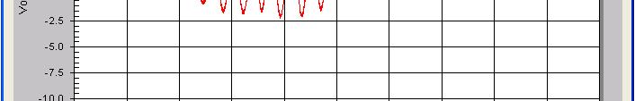
55 Effect of the Feedback Resistor The feedback resistor creates a current input into the charge amp that is proportional to the output voltage inverted from the output voltage This inversion causes the voltage to move in the opposite direction of its sign. This forces the output voltage to always move towards zero volts. Zero volts means zero current, making the output stable. The correction to zero volts begins immediately any time the output voltage leaves zero volts so distortion in your measured signal is always present. The amount of distortion is dependent upon the period of your signal vs the rate of correction. The correction rate for the EDU Sensor Board is proportional to the integrating capacitor multiplied times the feedback resistance value. 220pF 3.838GΩ 5 ~ 4.2 seconds. 55
56 Effect of the Feedback Resistor Applying a constant force to the sensor for a short period shows the correction function in action. Volts Time (seconds) The red line is the Sensor Board signal. The green dashed-line indicates the force that was applied as a theoretical step function. Note that the signal decays back to zero volts in 4.2 seconds after the first application of the force. A little later when the force is released, it looks to the sensor like a force in the opposite direction. This change also decays back to zero. Oscilloscope (real time) 56

57 Correcting the Feedback Leakage Clicking on this control tells the oscilloscope software to calculate the amount of leakage feeding back through the zeroing resistor and add it back to the signal after each sample point. 57
58 Correcting the Feedback Leakage The algorithm uses the resistor and capacitor values listed in the windows. These match the values of the components on the Sensor Board. Do not change them unless you change the board. 58
59 Correcting the Feedback Leakage The formula is Voltage Loss from Feedback Resistor += ( ) Measured Output Voltage + Offset Voltage ( Sample Period ) Feedback Resistance Integrating Capacitance This value is calculated for each sample point and added back to the measured value. The correction is cumulative over time ( i.e. +=). The feedback resistance will prevent the actual amplifier output voltage from saturating at +10V or -10V but the mathematical correction is cumulative and allows the plotted voltage value to exceed the ±10V limit. 59


60 Correcting the Feedback Leakage Correcting for the feedback resistance makes the circuit act like an integrator again, causing it to drift linearly in a positive or negative direction. The Offset Voltage lets you zero the drift. 60
61 Zeroing the Correction Drift. Drift of the signal with the Feedback Resistor Correction turned on but with the Offset Voltage set to zero. Note the checkmark indication for correction. 61


62 Zeroing the Correction Drift. The Offset Voltage can be adjusted to reduce the drift to zero. Press the Correct Offset button to have the software calculate the correction for you. 62

63 Correcting the Feedback Leakage The corrected Offset Voltage as calculated by the software. The software uses the slope of the last point on the screen taken against zero plus the elapsed time to calculate the drift and determine an offset voltage that will counteract it. 63

64 Zeroing the Correction Drift. The sensor drift after correction. Now, the system is ready to look at signals less than 60 seconds long (in this case). 64
65 Zeroing the Correction Drift. It might require more than one attempt to zero the drift to get the correction factor to the proper value. Each time the Correct Offset button is pressed, the new correction is added to the old value. To reset the Offset Voltage to zero, press the Reset Offset button. Air currents and vibrations in the area can have a significant impact on the corrected signal. Always place the sensor under a box, bowl, or other cover and let it stabilize for 10 minutes or so before executing the correction. Once the Offset Voltage is proper, you may uncover the sensor and use it. Covered, the sensor trace should eventually go straight with no curves. Uncovered, the signal will move in a seemingly random manner from air currents. You cannot get a good zero in this condition. 65


66 Integrating the Signal The second control integrates the signal over time. The Feedback Resistor Correction is automatically invoked so you should find a valid Offset Voltage before attempting to integrate the signal. Integrated signals go ballistic quickly! 66
67 Integrating the Signal What does the integrated signal mean? Assume that the force on the sample is caused by an acceleration. F = ma where m is the mass of the bumper on the sense capacitor and a is the acceleration that generated the force you measured. The integration of the force yields velocity. Therefore, applying force for a short period to the sensor capacitor is interpreted as an acceleration that lasted for the period of the force. If you have the Offset Voltage and the Scale Factor set correctly, the oscilloscope signal, meaning velocity, should increase during the application of the force and level off when you stop applying the force. 67


68 Preset Buttons The Force and Temperature preset buttons simply set up convenient values for the resistor, capacitor, and acquisition time parameters for their respective acquisition windows. 68
69 Force Measurements Measurement Parameters Effect of Touch Examples of different force measurements. 69
70 Measurement Parameters for Force Typical forces we may measure range in speed from Fast audio frequencies from 100Hz to 10KHz Intermediate speed forces such as your pulse that last a fraction of a second Slow force applications executed with your fingers, arms, etc. 70
71 Audio Set the Sample Period to the range of 1KHz up to 10KHz. At 1kHz, you can have a Time Window 20 seconds wide. At 10kHz, your Time Window can only be about 1.5 seconds wide. Place the sensor where it will be acted upon by an pressure wave. A simple demonstration is to put the sensor under your laptop and then rap on the table top! The Sensor Die is not suitable for picking up air pressure waves created by your voice as they will be 10 to 100 times too weak for the 220pF integrating capacitor to discriminate. Also, the acoustic impedance of the sensor capacitor to air is too high. The acoustic pressure waves will simply bounce off of the sensor. 71
72 Heart Beat Use the default acquisition timing. There will be a slight distortion of the pulse wave by the feedback resistor. Set the Advanced Controls to correct for the feedback resistor and zero the sensor board to get precise results. My pulse at the wrist using default settings and autoscale Oscilloscope (real time) Volts Time (seconds) 72
73 Finger Force These types of forces take seconds to develop and release. You must use feedback correction and zero the sensor before making this type of measurement to get an accurate signal shape. An interesting prediction is that it will be impossible for you to hold a constant, unvarying force on the sensor with your fingers! Try it! 73
74 Effects of Temperature on Force Measurements When you squeeze the bumpers of the sensor capacitor with your fingers, you are also heating the bumpers and the sense capacitor with your body heat. This heating will affect your measurements. Try applying the force with the eraser of a pencil. You can swing the sensor board through the air to see acceleration effects if you place a heavy mass on the sensor capacitor. However, the sensor capacitor will see air currents because of its motion and you may have a very hard time determining if the effects you see on the signal come from acceleration or from air-flow cooling of the sensor! Put the Sensor Board in a closed box and swing it around. 74
75 Temperature Measurements Measurement Parameters Examples of different temperature measurements. 75
76 Measurement Parameters for Temperature Some temperature changes can occur in a fraction of a second, especially if touch is involved. Temperature change by radiation or convection is slower, occurring over seconds or even a quarter of an hour. To make long term temperature measurements, use a Sample Period of 0.01 seconds and set the Time Window to 300 seconds (5 minutes) or longer. In order to see long term changes in temperature, you must use feedback correction and zero the amplifier for 300 seconds or longer. This test takes a long time to prepare: 10 minutes under the cover plus the zeroing runs of 10 minutes each. Once zero d for this long of a period, you can let the sensor run continuously for long periods without the measurement going unstable. 76
77 Some Temperature Measurements Leave the graph on autoscale using a Sliding Window for the X-Axis. Watch the constant changing of the signal due to air currents in the room. A classic example of the laws of thermodynamics in action. You will be able to see the cooling effect from the wind created when someone walks by or when the air conditioning fan turns on. Place your finger within an inch of the sensor capacitor. Your finger will noticeably heat the sensor by radiation. Create a sine wave on the signal using a hot coffee cup and a cold glass of water, alternating them next to the sensor! In all cases, note how abruptly the temperature changes when forced but how slowly it returns to ambient when the forcing function is removed. Demonstration of the rate of flow of energy governed by the temperature difference. 77
78 Special Considerations Changing the Graph while Running 60Hz noise Lock Up Running without the EDU 78
79 Changing the Graph While Running The graphics pop-up menu that you learned in IO4-Data Plotting Tools still apply. You may double-click the mouse with the cursor within the plotting area to get the plot configuration menu. You can use this feature to change the plot scales or go to autoscale while the oscilloscope is running. You can also Mark Data Points to highlight the signal. Note, however, that the marked data points take longer to plot so you may start generating acquisition errors. If you zoom into a signal during acquisition and subsequently STOP the trace, the zoom will remain in force even after you START again. You must Undo Zoom from the pop-up menu. 79
80 60Hz Noise The telephone cable connecting the Sensor Board to the EDU is an antenna for 60Hz or 50Hz EMF. You can minimize this effect by keeping the cable as short as practical. You are also an antenna for the 60Hz (50Hz) EMF so your body near the Sensor Board will inject significant noise. This is especially true when you touch the Sensor Board to your body to measure your pulse. The casing of the Sensor Board connector is metal and is grounded so holding the Sensor Board by the connector casing will eliminate almost all of the injected 60Hz. You, the antenna, will inject a countervening signal! The Sensor Board cable will distort Hysteresis measurements of small caps with its 60Hz noise. Disconnect the Sensor Board when running ferroelectric hysteresis loops. 80
81 Lock Up If the EDU locks up during operation, the oscilloscope controls will also not respond to your mouse commands as the computer is waiting for a response from the EDU to its USB queries. Should this happen, Power down the EDU. Cancel out of the oscilloscope code using the x box in the upper right hand corner of the window. Reconnect the EDU and start over. In the worst case, use the Task Manager (CNTRL-ALT-DEL) to force the program to quit. 81
82 Sleep If your computer goes to sleep with the EDU attached and powered up, the EDU will go to sleep as well, When you take your computer out of sleep mode, the EDU will also come out of sleep mode. However, the operating system will no longer recognize the EDU on its USB port. To re-connect the EDU in this situation, unplug the USB cable and then plug it back in again. There is no need to power down the EDU. 82
83 Running without the EDU If you start the EDU software without an EDU attached, the software will operate without locking up. You can examine all menus, recall files, and store files. Executing a hysteresis test will yield pseudo-data. The oscilloscope function will open but will not attempt to collect data. 83
84 Summary of the Rules Disconnect the EDU Sensor Board and its cable from the EDU when measuring Hysteresis Loops. Do not touch the sensor cap with your fingers. The heat pulse effect will swamp the force measurement. Hold the Sensor Board by the metal casing of its connector. Always cover the Sensor Board to isolate it from air currents when zeroing the Feedback Resistor Correction mode or when zeroing for integration. Make sure that the wires on either end of the Sensor Board cable go to the same pins of their respective plugs. A mistake here will destroy the Sensor Board. 84
85 Summary of the Rules Do not touch bare connections on the Sensor Board (other than the connector casing) when making measurements. The circuit will not be damaged but the measured signal will be distorted. You may connect and disconnect the Sensor Board to the EDU with the EDU powered up. You may use the pop-up menu graphing controls on the oscilloscope display while it is running. Always remember to UnZoom! 85
86 Contact Information We hope that you have enjoyed our tutorial about the Radiant EDU Oscilloscope and Sensor Board. You may contact us with questions or recommendations for the EDU and/or new ferroelectric-based components. Sales information: Michelle Bell Technical assistance: Joe Evans, Bob Howard, or Scott Chapman Shipping instructions: Geri Martinez Telephone: Fax: web site: 86
AD8232 EVALUATION BOARD DOCUMENTATION
 One Technology Way P.O. Box 9106 Norwood, MA 02062-9106 Tel: 781.329.4700 Fax: 781.461.3113 www.analog.com AD8232 EVALUATION BOARD DOCUMENTATION FEATURES Ready to use Heart Rate Monitor (HRM) Front end
LT Spice Getting Started Very Quickly. First Get the Latest Software!
 LT Spice Getting Started Very Quickly First Get the Latest Software! 1. After installing LT Spice, run it and check to make sure you have the latest version with respect to the latest version available
Large Signal Displacement Measurement with an Asylum SA Atomic Force Microscope Rev B
 Radiant Technologies, Inc. 2835D Pan American Freeway NE Albuquerque, NM 87107 Tel: 505-842-8007 Fax: 505-842-0366 e-mail: radiant@ferrodevices.com www.ferrodevices.com Large Signal Displacement Measurement
ECE 203 LAB 6: INVERTED PENDULUM
 Version 1.1 1 of 15 BEFORE YOU BEGIN EXPECTED KNOWLEDGE Basic Circuit Analysis EQUIPMENT AFG Oscilloscope Programmable Power Supply MATERIALS Three 741 Opamps TIP41 NPN power transistor TIP42 PNP power
Experiment 1: Instrument Familiarization (8/28/06)
") Electrical Measurement Issues Experiment 1: Instrument Familiarization (8/28/06) Electrical measurements are only as meaningful as the quality of the measurement techniques and the instrumentation applied
Electrical Measurement Issues Experiment 1: Instrument Familiarization (8/28/06) Electrical measurements are only as meaningful as the quality of the measurement techniques and the instrumentation applied
Gentec-EO USA. T-RAD-USB Users Manual. T-Rad-USB Operating Instructions /15/2010 Page 1 of 24
 Gentec-EO USA T-RAD-USB Users Manual Gentec-EO USA 5825 Jean Road Center Lake Oswego, Oregon, 97035 503-697-1870 voice 503-697-0633 fax 121-201795 11/15/2010 Page 1 of 24 System Overview Welcome to the
LVTX-10 Series Ultrasonic Sensor Installation and Operation Guide
 LVTX-10 Series Ultrasonic Sensor Installation and Operation Guide M-5578/0516 M-5578/0516 Section TABLE OF CONTENTS 1 Introduction... 1 2 Quick Guide on Getting Started... 2 Mounting the LVTX-10 Series
Experiment 1: Instrument Familiarization
 Electrical Measurement Issues Experiment 1: Instrument Familiarization Electrical measurements are only as meaningful as the quality of the measurement techniques and the instrumentation applied to the
Operational Amplifiers
 Operational Amplifiers Table of contents 1. Design 1.1. The Differential Amplifier 1.2. Level Shifter 1.3. Power Amplifier 2. Characteristics 3. The Opamp without NFB 4. Linear Amplifiers 4.1. The Non-Inverting
Large Signal Displacement Measurement with an MTI Photonic Sensor Rev B
 Radiant Technologies, Inc. 2835D Pan American Freeway NE Albuquerque, NM 8717 Tel: 55-842-87 Fax: 55-842-366 e-mail: radiant@ferrodevices.com www.ferrodevices.com Large Signal Displacement Measurement
Application Note: Precision Displacement Test Stand Rev A
 Radiant Technologies, Inc. 2835D Pan American Freeway NE Albuquerque, NM 87107 Tel: 505-842-8007 Fax: 505-842-0366 e-mail: radiant@ferrodevices.com www.ferrodevices.com Application Note: Precision Displacement
Chapter 13: Comparators
 Chapter 13: Comparators So far, we have used op amps in their normal, linear mode, where they follow the op amp Golden Rules (no input current to either input, no voltage difference between the inputs).
Pre-Lab. Introduction
 Pre-Lab Read through this entire lab. Perform all of your calculations (calculated values) prior to making the required circuit measurements. You may need to measure circuit component values to obtain
EMG Electrodes. Fig. 1. System for measuring an electromyogram.
 1270 LABORATORY PROJECT NO. 1 DESIGN OF A MYOGRAM CIRCUIT 1. INTRODUCTION 1.1. Electromyograms The gross muscle groups (e.g., biceps) in the human body are actually composed of a large number of parallel
University of Utah Electrical Engineering Department ECE 2100 Experiment No. 2 Linear Operational Amplifier Circuits II
 University of Utah Electrical Engineering Department ECE 2100 Experiment No. 2 Linear Operational Amplifier Circuits II Minimum required points = 51 Grade base, 100% = 85 points Recommend parts should
Experiment P11: Newton's Second Law Constant Force (Force Sensor, Motion Sensor)
") PASCO scientific Physics Lab Manual: P11-1 Experiment P11: Newton's Second Law Constant Force (Force Sensor, Motion Sensor) Concept Time SW Interface Macintosh file Windows file Newton s Laws 30 m 500
PASCO scientific Physics Lab Manual: P11-1 Experiment P11: Newton's Second Law Constant Force (Force Sensor, Motion Sensor) Concept Time SW Interface Macintosh file Windows file Newton s Laws 30 m 500
The Oscilloscope. Vision is the art of seeing things invisible. J. Swift ( ) OBJECTIVE To learn to operate a digital oscilloscope.
 OBJECTIVE To learn to operate a digital oscilloscope.") The Oscilloscope Vision is the art of seeing things invisible. J. Swift (1667-1745) OBJECTIVE To learn to operate a digital oscilloscope. THEORY The oscilloscope, or scope for short, is a device for drawing
The Oscilloscope Vision is the art of seeing things invisible. J. Swift (1667-1745) OBJECTIVE To learn to operate a digital oscilloscope. THEORY The oscilloscope, or scope for short, is a device for drawing
Technical Report MFIS and TFFT Testing with the Premier II Tester Rev C
 Radiant Technologies, Inc. 2835D Pan American Freeway NE Albuquerque, NM 87107 Tel: 505-842-8007 Fax: 505-842-0366 e-mail: radiant@ferrodevices.com Technical Report MFIS and TFFT Testing with the Premier
ALM473 DUAL MONO \ STEREO AUDIO LEVEL MASTER OPERATION MANUAL IB
 ALM473 DUAL MONO \ STEREO AUDIO LEVEL MASTER OPERATION MANUAL IB6408-01 TABLE OF CONTENTS GENERAL DESCRIPTION 2 INSTALLATION 2,3,4 CONNECTION AND SETUP 4,5,6,7 FUNCTIONAL DESCRIPTION 8,9 MAINTENANCE 9
Testing Power Sources for Stability
 Keywords Venable, frequency response analyzer, oscillator, power source, stability testing, feedback loop, error amplifier compensation, impedance, output voltage, transfer function, gain crossover, bode
ME 365 EXPERIMENT 1 FAMILIARIZATION WITH COMMONLY USED INSTRUMENTATION
 Objectives: ME 365 EXPERIMENT 1 FAMILIARIZATION WITH COMMONLY USED INSTRUMENTATION The primary goal of this laboratory is to study the operation and limitations of several commonly used pieces of instrumentation:
User s Manual for Integrator Short Pulse ISP16 10JUN2016
 User s Manual for Integrator Short Pulse ISP16 10JUN2016 Specifications Exceeding any of the Maximum Ratings and/or failing to follow any of the Warnings and/or Operating Instructions may result in damage
ET 304A Laboratory Tutorial-Circuitmaker For Transient and Frequency Analysis
 ET 304A Laboratory Tutorial-Circuitmaker For Transient and Frequency Analysis All circuit simulation packages that use the Pspice engine allow users to do complex analysis that were once impossible to
EE320L Electronics I. Laboratory. Laboratory Exercise #2. Basic Op-Amp Circuits. Angsuman Roy. Department of Electrical and Computer Engineering
 EE320L Electronics I Laboratory Laboratory Exercise #2 Basic Op-Amp Circuits By Angsuman Roy Department of Electrical and Computer Engineering University of Nevada, Las Vegas Objective: The purpose of
ECE3204 D2015 Lab 1. See suggested breadboard configuration on following page!
 ECE3204 D2015 Lab 1 The Operational Amplifier: Inverting and Non-inverting Gain Configurations Gain-Bandwidth Product Relationship Frequency Response Limitation Transfer Function Measurement DC Errors
Physics 303 Fall Module 4: The Operational Amplifier
 Module 4: The Operational Amplifier Operational Amplifiers: General Introduction In the laboratory, analog signals (that is to say continuously variable, not discrete signals) often require amplification.
LAB I. INTRODUCTION TO LAB EQUIPMENT
 1. OBJECTIVE LAB I. INTRODUCTION TO LAB EQUIPMENT In this lab you will learn how to properly operate the oscilloscope Agilent MSO6032A, the Keithley Source Measure Unit (SMU) 2430, the function generator
RC Filters and Basic Timer Functionality
 RC-1 Learning Objectives: RC Filters and Basic Timer Functionality The student who successfully completes this lab will be able to: Build circuits using passive components (resistors and capacitors) from
Week 8 AM Modulation and the AM Receiver
 Week 8 AM Modulation and the AM Receiver The concept of modulation and radio transmission is introduced. An AM receiver is studied and the constructed on the prototyping board. The operation of the AM
BIO 365L Neurobiology Laboratory. Training Exercise 1: Introduction to the Computer Software: DataPro
 BIO 365L Neurobiology Laboratory Training Exercise 1: Introduction to the Computer Software: DataPro 1. Don t Panic. When you run DataPro, you will see a large number of windows, buttons, and boxes. In
Experiment P01: Understanding Motion I Distance and Time (Motion Sensor)
") PASCO scientific Physics Lab Manual: P01-1 Experiment P01: Understanding Motion I Distance and Time (Motion Sensor) Concept Time SW Interface Macintosh file Windows file linear motion 30 m 500 or 700 P01
PASCO scientific Physics Lab Manual: P01-1 Experiment P01: Understanding Motion I Distance and Time (Motion Sensor) Concept Time SW Interface Macintosh file Windows file linear motion 30 m 500 or 700 P01
Built-in soft-start feature. Up-Slope and Down-Slope. Power-Up safe start feature. Motor will only start if pulse of 1.5ms is detected.
 Thank You for purchasing our TRI-Mode programmable DC Motor Controller. Our DC Motor Controller is the most flexible controller you will find. It is user-programmable and covers most applications. This
ECE 317 Laboratory #1 Force Sensitive Resistors
 ECE 317 Laboratory #1 Force Sensitive Resistors Background Force, pressure, and position sensing are required for a wide variety of uses. In this lab, we will investigate a sensor called a force sensitive
UCE-DSO212 DIGITAL OSCILLOSCOPE USER MANUAL. UCORE ELECTRONICS
 UCE-DSO212 DIGITAL OSCILLOSCOPE USER MANUAL UCORE ELECTRONICS www.ucore-electronics.com 2017 Contents 1. Introduction... 2 2. Turn on or turn off... 3 3. Oscilloscope Mode... 4 3.1. Display Description...
The Allen-Bradley Servo Interface Module (Cat. No SF1) when used with the Micro Controller (Cat. No UC1) can control single axis
 when used with the Micro Controller (Cat. No UC1) can control single axis") Table of Contents The Allen-Bradley Servo Interface Module (Cat. No. 1771-SF1) when used with the Micro Controller (Cat. No. 1771-UC1) can control single axis positioning systems such as found in machine
Table of Contents The Allen-Bradley Servo Interface Module (Cat. No. 1771-SF1) when used with the Micro Controller (Cat. No. 1771-UC1) can control single axis positioning systems such as found in machine
Experiment 8: An AC Circuit
 Experiment 8: An AC Circuit PART ONE: AC Voltages. Set up this circuit. Use R = 500 Ω, L = 5.0 mh and C =.01 μf. A signal generator built into the interface provides the emf to run the circuit from Output
OPERATING INSTRUCTIONS AND SYSTEM DESCRIPTION FOR THE. ISO-STIM 01D STIMULUS ISOLATION UNIT ±100 V / ±10 ma, bipolar output
 OPERATING INSTRUCTIONS AND SYSTEM DESCRIPTION FOR THE ISO-STIM 01D STIMULUS ISOLATION UNIT ±100 V / ±10 ma, bipolar output VERSION 4.0 npi 2014 npi electronic GmbH, Bauhofring 16, D-71732 Tamm, Germany
Low Cost, General Purpose High Speed JFET Amplifier AD825
 a FEATURES High Speed 41 MHz, 3 db Bandwidth 125 V/ s Slew Rate 8 ns Settling Time Input Bias Current of 2 pa and Noise Current of 1 fa/ Hz Input Voltage Noise of 12 nv/ Hz Fully Specified Power Supplies:
FlatPack Ultrasonic Sensors
 FlatPack Ultrasonic Sensors Installation & Operation Guide May 23, 2017 The FlatPack Sensor product line listed in the introduction of this manual complies with the European Council EMC Directive 2004/108/EC
Smoking and any food or drinks are not permitted in the Applications Lab!
 Pre-Lab Activities: None 220 Lab A Electrical Properties of Transmission Systems and the Local Loop Purpose of the experiment: Experiment with a telephone and view its properties under various different
Draw in the space below a possible arrangement for the resistor and capacitor. encapsulated components
 1). An encapsulated component is known to consist of a resistor and a capacitor. It has two input terminals and two output terminals. A 5V, 1kHz square wave signal is connected to the input terminals and
The Discussion of this exercise covers the following points:
 Exercise 3-2 Frequency-Modulated CW Radar EXERCISE OBJECTIVE When you have completed this exercise, you will be familiar with FM ranging using frequency-modulated continuous-wave (FM-CW) radar. DISCUSSION
When you have completed this exercise, you will be able to relate the gain and bandwidth of an op amp
 Op Amp Fundamentals When you have completed this exercise, you will be able to relate the gain and bandwidth of an op amp In general, the parameters are interactive. However, in this unit, circuit input
Sweep / Function Generator User Guide
 I. Overview Sweep / Function Generator User Guide The Sweep/Function Generator as developed by L. J. Haskell was designed and built as a multi-functional test device to help radio hobbyists align antique
Table of Contents TABLE OF CONTENTS...I TABLE OF FIGURES...III C - QUIKLOOK SETUP...22
 Table of Contents TABLE OF CONTENTS...I TABLE OF FIGURES...III A - DISCUSSION...1 B MAIN SETUP...6 B.1 - Setup Dialog...6 B.2 Description...7 B.3 Controls...9 B-4-48-Channel Multiplexer Configuration...12
EXPERIMENT NUMBER 2 BASIC OSCILLOSCOPE OPERATIONS
 1 EXPERIMENT NUMBER 2 BASIC OSCILLOSCOPE OPERATIONS The oscilloscope is the most versatile and most important tool in this lab and is probably the best tool an electrical engineer uses. This outline guides
LM13600 Dual Operational Transconductance Amplifiers with Linearizing Diodes and Buffers
 LM13600 Dual Operational Transconductance Amplifiers with Linearizing Diodes and Buffers General Description The LM13600 series consists of two current controlled transconductance amplifiers each with
Introduction to oscilloscope. and time dependent circuits
 Physics 9 Intro to oscilloscope, v.1.0 p. 1 NAME: SECTION DAY/TIME: TA: LAB PARTNER: Introduction to oscilloscope and time dependent circuits Introduction In this lab, you ll learn the basics of how to
MegaPoints Controller
 MegaPoints Controller A flexible solution and modular component for controlling model railway points and semaphore signals using inexpensive servos. User guide Revision 10c March 2015 MegaPoints Controllers
total j = BA, [1] = j [2] total
![total j = BA, [1] = j [2] total](/thumbs/85/91692343.jpg "total j = BA, [1] = j [2] total") Name: S.N.: Experiment 2 INDUCTANCE AND LR CIRCUITS SECTION: PARTNER: DATE: Objectives Estimate the inductance of the solenoid used for this experiment from the formula for a very long, thin, tightly wound
Name: S.N.: Experiment 2 INDUCTANCE AND LR CIRCUITS SECTION: PARTNER: DATE: Objectives Estimate the inductance of the solenoid used for this experiment from the formula for a very long, thin, tightly wound
Activity P52: LRC Circuit (Voltage Sensor)
") Activity P52: LRC Circuit (Voltage Sensor) Concept DataStudio ScienceWorkshop (Mac) ScienceWorkshop (Win) AC circuits P52 LRC Circuit.DS (See end of activity) (See end of activity) Equipment Needed Qty
Activity P52: LRC Circuit (Voltage Sensor) Concept DataStudio ScienceWorkshop (Mac) ScienceWorkshop (Win) AC circuits P52 LRC Circuit.DS (See end of activity) (See end of activity) Equipment Needed Qty
EE 3305 Lab I Revised July 18, 2003
 Operational Amplifiers Operational amplifiers are high-gain amplifiers with a similar general description typified by the most famous example, the LM741. The LM741 is used for many amplifier varieties
Lab 15: Lock in amplifier (Version 1.4)
") Lab 15: Lock in amplifier (Version 1.4) WARNING: Use electrical test equipment with care! Always double-check connections before applying power. Look for short circuits, which can quickly destroy expensive
Lab 15: Lock in amplifier (Version 1.4) WARNING: Use electrical test equipment with care! Always double-check connections before applying power. Look for short circuits, which can quickly destroy expensive
Experiment P24: Motor Efficiency (Photogate, Power Amplifier, Voltage Sensor)
") PASCO scientific Physics Lab Manual: P24-1 Experiment P24: Motor Efficiency (Photogate, Power Amplifier, Voltage Sensor) Concept Time SW Interface Macintosh File Windows File energy 30 m 700 P24 Motor
PASCO scientific Physics Lab Manual: P24-1 Experiment P24: Motor Efficiency (Photogate, Power Amplifier, Voltage Sensor) Concept Time SW Interface Macintosh File Windows File energy 30 m 700 P24 Motor
SigCal32 User s Guide Version 3.0
 SigCal User s Guide . . SigCal32 User s Guide Version 3.0 Copyright 1999 TDT. All rights reserved. No part of this manual may be reproduced or transmitted in any form or by any means, electronic or mechanical,
Physics 120 Lab 1 (2018) - Instruments and DC Circuits
 - Instruments and DC Circuits") Physics 120 Lab 1 (2018) - Instruments and DC Circuits Welcome to the first laboratory exercise in Physics 120. Your state-of-the art equipment includes: Digital oscilloscope w/usb output for SCREENSHOTS.
Physics 120 Lab 1 (2018) - Instruments and DC Circuits Welcome to the first laboratory exercise in Physics 120. Your state-of-the art equipment includes: Digital oscilloscope w/usb output for SCREENSHOTS.
Switched Mode Power Supply Measurements
 Power Analysis 1 Switched Mode Power Supply Measurements AC Input Power measurements Safe operating area Harmonics and compliance Efficiency Switching Transistor Losses Measurement challenges Transformer
Standard Configuration
 Radiant Technologies, Inc. 2835D Pan American Freeway NE Albuquerque, NM 87107 Tel: 505-842-8007 Fax: 505-842-0366 e-mail: radiant@ferrodevices.com 9 April, 2009 From: Scott P. Chapman Radiant Technologies,
The DC Machine Laboration 3
 EIEN25 - Power Electronics: Devices, Converters, Control and Applications The DC Machine Laboration 3 Updated February 19, 2018 1. Before the lab, look through the manual and make sure you are familiar
Sampling and Reconstruction
 Experiment 10 Sampling and Reconstruction In this experiment we shall learn how an analog signal can be sampled in the time domain and then how the same samples can be used to reconstruct the original
University of Utah Electrical & Computer Engineering Department ECE 2210/2200 Lab 4 Oscilloscope
 University of Utah Electrical & Computer Engineering Department ECE 2210/2200 Lab 4 Oscilloscope Objectives 1 Introduce the Oscilloscope and learn some uses. 2 Observe Audio signals. 3 Introduce the Signal
Notes on Experiment #1
 Notes on Experiment #1 Bring graph paper (cm cm is best) From this week on, be sure to print a copy of each experiment and bring it with you to lab. There will not be any experiment copies available in
Pololu Dual G2 High-Power Motor Driver for Raspberry Pi
 Pololu Dual G2 High-Power Motor Driver for Raspberry Pi 24v14 /POLOLU 3752 18v18 /POLOLU 3750 18v22 /POLOLU 3754 This add-on board makes it easy to control two highpower DC motors with a Raspberry Pi.
Experiment 2. Ohm s Law. Become familiar with the use of a digital voltmeter and a digital ammeter to measure DC voltage and current.
 Experiment 2 Ohm s Law 2.1 Objectives Become familiar with the use of a digital voltmeter and a digital ammeter to measure DC voltage and current. Construct a circuit using resistors, wires and a breadboard
Temperature Monitoring and Fan Control with Platform Manager 2
 August 2013 Introduction Technical Note TN1278 The Platform Manager 2 is a fast-reacting, programmable logic based hardware management controller. Platform Manager 2 is an integrated solution combining
Assembly Instructions
 Assembly Instructions For the SSQ-2F 3.1 MHz Rife Controller Board Kit v1.41 Manual v1.00 2012 by Ralph Hartwell Spectrotek Services GENERAL ASSEMBLY INSTRUCTIONS Arrange for a clean work surface with
Name Date: Course number: MAKE SURE TA & TI STAMPS EVERY PAGE BEFORE YOU START EXPERIMENT 10. Electronic Circuits
 Laboratory Section: Last Revised on September 21, 2016 Partners Names: Grade: EXPERIMENT 10 Electronic Circuits 1. Pre-Laboratory Work [2 pts] 1. How are you going to determine the capacitance of the unknown
CI-22. BASIC ELECTRONIC EXPERIMENTS with computer interface. Experiments PC1-PC8. Sample Controls Display. Instruction Manual
 CI-22 BASIC ELECTRONIC EXPERIMENTS with computer interface Experiments PC1-PC8 Sample Controls Display See these Oscilloscope Signals See these Spectrum Analyzer Signals Instruction Manual Elenco Electronics,
T6+ Analog I/O Section. Installation booklet for part numbers: 5/4-80A-115 5/4-90A-115 5/4-80A /4-90A-1224
 T and T+ are trade names of Trol Systems Inc. TSI reserves the right to make changes to the information contained in this manual without notice. publication /4A115MAN- rev:1 2001 TSI All rights reserved
ESE 150 Lab 04: The Discrete Fourier Transform (DFT)
") LAB 04 In this lab we will do the following: 1. Use Matlab to perform the Fourier Transform on sampled data in the time domain, converting it to the frequency domain 2. Add two sinewaves together of differing
LAB 04 In this lab we will do the following: 1. Use Matlab to perform the Fourier Transform on sampled data in the time domain, converting it to the frequency domain 2. Add two sinewaves together of differing
OVEN INDUSTRIES, INC. Model 5C7-362
 OVEN INDUSTRIES, INC. OPERATING MANUAL Model 5C7-362 THERMOELECTRIC MODULE TEMPERATURE CONTROLLER TABLE OF CONTENTS Features... 1 Description... 2 Block Diagram... 3 RS232 Communications Connections...
EE 201 Function / Arbitrary Waveform Generator and Oscilloscope Tutorial
 EE 201 Function / Arbitrary Waveform Generator and Oscilloscope Tutorial 1 This is a programmed learning instruction manual. It is written for the Agilent DSO3202A Digital Storage Oscilloscope. The prerequisite
Lab 3: AC Low pass filters (version 1.3)
") Lab 3: AC Low pass filters (version 1.3) WARNING: Use electrical test equipment with care! Always double-check connections before applying power. Look for short circuits, which can quickly destroy expensive
Lab 3: AC Low pass filters (version 1.3) WARNING: Use electrical test equipment with care! Always double-check connections before applying power. Look for short circuits, which can quickly destroy expensive
Radar Shield System Design
 University of California, Davis EEC 193 Final Project Report Radar Shield System Design Lit Po Kwong: lkwong853@gmail.com Yuyang Xie: szyuyxie@gmail.com Ivan Lee: yukchunglee@hotmail.com Ri Liang: joeliang914@gmail.com
Frequency Selective Circuits
 Lab 15 Frequency Selective Circuits Names Objectives in this lab you will Measure the frequency response of a circuit Determine the Q of a resonant circuit Build a filter and apply it to an audio signal
KH103 Fast Settling, High Current Wideband Op Amp
 KH103 Fast Settling, High Current Wideband Op Amp Features 80MHz full-power bandwidth (20V pp, 100Ω) 200mA output current 0.4% settling in 10ns 6000V/µs slew rate 4ns rise and fall times (20V) Direct replacement
10: AMPLIFIERS. Circuit Connections in the Laboratory. Op-Amp. I. Introduction
 10: AMPLIFIERS Circuit Connections in the Laboratory From now on you will construct electrical circuits and test them. The usual way of constructing circuits would be to solder each electrical connection
Chapter 2 Signal Conditioning, Propagation, and Conversion
 09/0 PHY 4330 Instrumentation I Chapter Signal Conditioning, Propagation, and Conversion. Amplification (Review of Op-amps) Reference: D. A. Bell, Operational Amplifiers Applications, Troubleshooting,
Akiyama-Probe (A-Probe) technical guide This technical guide presents: how to make a proper setup for operation of Akiyama-Probe.
 technical guide This technical guide presents: how to make a proper setup for operation of Akiyama-Probe.") Akiyama-Probe (A-Probe) technical guide This technical guide presents: how to make a proper setup for operation of Akiyama-Probe. Version: 2.0 Introduction To benefit from the advantages of Akiyama-Probe,
Akiyama-Probe (A-Probe) technical guide This technical guide presents: how to make a proper setup for operation of Akiyama-Probe. Version: 2.0 Introduction To benefit from the advantages of Akiyama-Probe,
QUICK START GUIDE FOR DEMONSTRATION CIRCUIT BIT DIFFERENTIAL INPUT DELTA SIGMA ADC LTC DESCRIPTION
 LTC2433-1 DESCRIPTION Demonstration circuit 745 features the LTC2433-1, a 16-bit high performance Σ analog-to-digital converter (ADC). The LTC2433-1 features 0.12 LSB linearity, 0.16 LSB full-scale accuracy,
Experiment P10: Acceleration of a Dynamics Cart II (Motion Sensor)
") PASCO scientific Physics Lab Manual: P10-1 Experiment P10: (Motion Sensor) Concept Time SW Interface Macintosh file Windows file Newton s Laws 30 m 500 or 700 P10 Cart Acceleration II P10_CAR2.SWS EQUIPMENT
PASCO scientific Physics Lab Manual: P10-1 Experiment P10: (Motion Sensor) Concept Time SW Interface Macintosh file Windows file Newton s Laws 30 m 500 or 700 P10 Cart Acceleration II P10_CAR2.SWS EQUIPMENT
Amptek sets the New State-of-the-Art... Again! with Cooled FET
 Amptek sets the New State-of-the-Art... Again! with Cooled FET RUN SILENT...RUN FAST...RUN COOL! Performance Noise: 670 ev FWHM (Si) ~76 electrons RMS Noise Slope: 11.5 ev/pf High Ciss FET Fast Rise Time:
Resonance Tube. 1 Purpose. 2 Theory. 2.1 Air As A Spring. 2.2 Traveling Sound Waves in Air
 Resonance Tube Equipment Capstone, complete resonance tube (tube, piston assembly, speaker stand, piston stand, mike with adapters, channel), voltage sensor, 1.5 m leads (2), (room) thermometer, flat rubber
There is a twenty db improvement in the reflection measurements when the port match errors are removed.
 ABSTRACT Many improvements have occurred in microwave error correction techniques the past few years. The various error sources which degrade calibration accuracy is better understood. Standards have been
UCE-DSO210 DIGITAL OSCILLOSCOPE USER MANUAL. FATIH GENÇ UCORE ELECTRONICS REV1
 UCE-DSO210 DIGITAL OSCILLOSCOPE USER MANUAL FATIH GENÇ UCORE ELECTRONICS www.ucore-electronics.com 2017 - REV1 Contents 1. Introduction... 2 2. Turn on or turn off... 3 3. Oscilloscope Mode... 3 3.1. Display
LAB 8: Activity P52: LRC Circuit
 LAB 8: Activity P52: LRC Circuit Equipment: Voltage Sensor 1 Multimeter 1 Patch Cords 2 AC/DC Electronics Lab (100 μf capacitor; 10 Ω resistor; Inductor Coil; Iron core; 5 inch wire lead) The purpose of
LM146/LM346 Programmable Quad Operational Amplifiers
 LM146/LM346 Programmable Quad Operational Amplifiers General Description The LM146 series of quad op amps consists of four independent, high gain, internally compensated, low power, programmable amplifiers.
Experiment 3. Ohm s Law. Become familiar with the use of a digital voltmeter and a digital ammeter to measure DC voltage and current.
 Experiment 3 Ohm s Law 3.1 Objectives Become familiar with the use of a digital voltmeter and a digital ammeter to measure DC voltage and current. Construct a circuit using resistors, wires and a breadboard
DC and AC Circuits. Objective. Theory. 1. Direct Current (DC) R-C Circuit
 R-C Circuit") [International Campus Lab] Objective Determine the behavior of resistors, capacitors, and inductors in DC and AC circuits. Theory ----------------------------- Reference -------------------------- Young
[International Campus Lab] Objective Determine the behavior of resistors, capacitors, and inductors in DC and AC circuits. Theory ----------------------------- Reference -------------------------- Young
Specify Gain and Phase Margins on All Your Loops
 Keywords Venable, frequency response analyzer, power supply, gain and phase margins, feedback loop, open-loop gain, output capacitance, stability margins, oscillator, power electronics circuits, voltmeter,
Single Supply, Rail to Rail Low Power FET-Input Op Amp AD820
 a FEATURES True Single Supply Operation Output Swings Rail-to-Rail Input Voltage Range Extends Below Ground Single Supply Capability from + V to + V Dual Supply Capability from. V to 8 V Excellent Load
Peak Current. Continuous Current. See Part Numbering Information on last page of datasheet for additional ordering options.
 Description Power Range The PWM servo drive is designed to drive brushless DC motors at a high switching frequency. A single red/green LED indicates operating status. The drive is fully protected against
INSTRUCTION MANUAL. Force Transducer Output Tube Repair Kit
 INSTRUCTION MANUAL Model 400-TR Force Transducer Output Tube Repair Kit June 4, 2004, Revision 5 Copyright 2004 Aurora Scientific Inc. Aurora Scientific Inc. 360 Industrial Pkwy. S., Unit 4 Aurora, Ontario,
PRODUCT DEMODULATION - SYNCHRONOUS & ASYNCHRONOUS
 PRODUCT DEMODULATION - SYNCHRONOUS & ASYNCHRONOUS INTRODUCTION...98 frequency translation...98 the process...98 interpretation...99 the demodulator...100 synchronous operation: ω 0 = ω 1...100 carrier
M-300 & M-320 Low Cost Ultrasonic Sensors
 M-300 & M-320 Family of Low Cost Ultrasonic Sensors December 23, 2014 Copyright 2014 by Massa Products Corporation. All rights reserved. Section TABLE OF CONTENTS Page 1 Introduction... 1 2 Quick Guide
ME 461 Laboratory #5 Characterization and Control of PMDC Motors
 ME 461 Laboratory #5 Characterization and Control of PMDC Motors Goals: 1. Build an op-amp circuit and use it to scale and shift an analog voltage. 2. Calibrate a tachometer and use it to determine motor
Experiment P20: Driven Harmonic Motion - Mass on a Spring (Force Sensor, Motion Sensor, Power Amplifier)
") PASCO scientific Physics Lab Manual: P20-1 Experiment P20: - Mass on a Spring (Force Sensor, Motion Sensor, Power Amplifier) Concept Time SW Interface Macintosh file Windows file harmonic motion 45 m 700
PASCO scientific Physics Lab Manual: P20-1 Experiment P20: - Mass on a Spring (Force Sensor, Motion Sensor, Power Amplifier) Concept Time SW Interface Macintosh file Windows file harmonic motion 45 m 700
Rowan University Freshman Clinic I Lab Project 2 The Operational Amplifier (Op Amp)
") Rowan University Freshman Clinic I Lab Project 2 The Operational Amplifier (Op Amp) Objectives Become familiar with an Operational Amplifier (Op Amp) electronic device and it operation Learn several basic
Rowan University Freshman Clinic I Lab Project 2 The Operational Amplifier (Op Amp) Objectives Become familiar with an Operational Amplifier (Op Amp) electronic device and it operation Learn several basic
When input, output and feedback voltages are all symmetric bipolar signals with respect to ground, no biasing is required.
 1 When input, output and feedback voltages are all symmetric bipolar signals with respect to ground, no biasing is required. More frequently, one of the items in this slide will be the case and biasing
Experiment P02: Understanding Motion II Velocity and Time (Motion Sensor)
") PASCO scientific Physics Lab Manual: P02-1 Experiment P02: Understanding Motion II Velocity and Time (Motion Sensor) Concept Time SW Interface Macintosh file Windows file linear motion 30 m 500 or 700
PASCO scientific Physics Lab Manual: P02-1 Experiment P02: Understanding Motion II Velocity and Time (Motion Sensor) Concept Time SW Interface Macintosh file Windows file linear motion 30 m 500 or 700