Akiyama-Probe (A-Probe) technical guide This technical guide presents: how to make a proper setup for operation of Akiyama-Probe.
|
|
|
- Cameron Chambers
- 5 years ago
- Views:
Transcription


1 Akiyama-Probe (A-Probe) technical guide This technical guide presents: how to make a proper setup for operation of Akiyama-Probe. Version: 2.0

2 Introduction To benefit from the advantages of Akiyama-Probe, a proper operation setup is required. In order to save some time and effort, a commercial instrument should be the first choice. One can obtain the best performance in a shorted time. An alternative to the commercially available/offered solution is building one s own setup. This technical guide is intended for those who prefer the latter. Many examples and suggestions in this guide will help to overcome common problems at the first step. The recommended operation mode for Akiyama-Probe is dynamic mode with the frequency modulation (FM) detection (self-oscillation). The amplitude modulation (AM) detection (fixed driving frequency) is also feasible, if one would accept a slower scan speed and compromise on spatial resolution. The following points have to be considered to build an own setup: How to physically fix Akiyama-Probe with two electrical connections Electrical configuration (self-oscillation, frequency measurement) pre-amplifier electronics for self-oscillation phase locked loop (PLL) Note that some contents in this guide may not apply to your specific setup. Please use this guide as a This is for general reference only. Akiyama-Probe is a patented technology. Akiyama-Probe Since 2006

3 Operation setup Commercial instruments: Many instruments and equipment (AFM, PLL, amplifiers and etc.) are commercially available for Akiyama-Probe operation. They are very reliable and highly recommended to use. Build your own setup with analog electronics: A self-oscillation circuit can be built with some OP-amps. In a simple case, the PLL can be outside of the self-oscillation loop and works in a passive mode. If a single chip PLL (e.g., 4046) is used, a complete setup can be built with a low budget. If a higher resolution is required in this configuration, the simple PLL can be replaced with a more accurate commercial PLL without any major modification of the setup. M. Ferrara, Nanotechnology 14, (2003) J. Jersch, et al., Rev. Sci. Instrum. 77, (2006) H.-P. Rust, et al., Rev. Sci. Instrum. 77, (2006) E.g., Tuning Fork Sensor Controller by NanoAndMore Laboratory standard instruments + minimum analog electronics: One can make a very high performance self-oscillation + PLL setup with two standard laboratory instruments (lock-in amplifier and frequency synthesizer) and a very simple analog circuit. The analog circuit with a few OP-amps forms a proportional-integral gain controller. J. Rychen, et al., Rev. Sci. Instrum. 70, 2765 (1999) J. Jersch, H. Fuchs. IEEE Int. Freq. Cont. Symp. Forum, (2007)
 l w Cantilever Tip Force constant")

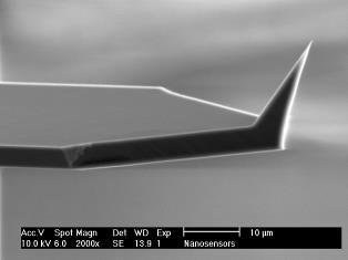
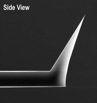
 AdvancedTEC -like tip radius <15")

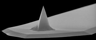
4 Akiyama-Probe specifications ~ 3 mm Specifications (typical values) l w Cantilever Tip Force constant Resonance frequency Ceramic plate length: 310 µm, thickness: 3.7 µm, width: 30 µm each material: n + silicon ( Ohm cm) AdvancedTEC -like tip radius <15 nm, tip height 28 µm 5 N/m (Si cantilever) ~ 50 khz approximately 6.5 mm x 5.1 mm x 0.4 mm All values are subject to change without notice.


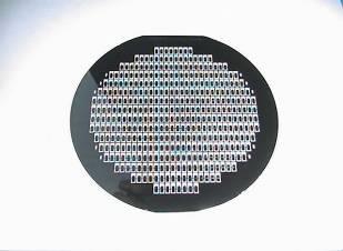
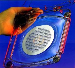
5 Ceramic plate To remove from Gel-sheet Twist & pick up Larger than 2 mm This side is electrically connected to the cantilever. (mm) NANOSENSORS original ceramic plate for Akiyama-Probe with two gold contacts and three through holes. All through holes have the same size and can be used for centering the plate on a counterpart that has three spheres. The thickness is approximately 0.4 mm.
6 Amplifier circuit (1a) Attenuation 10:1 IN 20k R1 1Vp-p ~ 3 Vp-p at the input is reasonable to start a test. C1 180p - + 2k R2 A large ground plane directly connected to the positive input of the amp is effective against noise Connected* Shorter is better OPamp: low input bias type e.g. AD8512, AD712, etc. Guarding 22M R4-1M~22M 10k R C4 100p 10k R6 OUT 20k VR Tune to obtain an optimum output k R3 C2 1.0p Parasitic capacitance compensation *The silicon cantilever and tip is electrically connected to the left pad of the ceramic plate. In this configuration, the cantilever and tip should have the virtual ground potential. All resistors and capacitors may have to be trimmed accordingly.
7 Amplifier circuit (1b) 1Vp-p ~ 3 Vp-p at the input is reasonable to start a test. IN 20k R1 C1 180p - + 2k R2 Attenuation 10:1 A large ground plane directly connected to the positive input of the amp is effective against noise Connected* Shorter is better OPamp: low input bias type e.g. AD8512, AD712, etc. Guarding 22M R4-1M~22M 10k R C4 100p 10k R6 OUT C2 1.0p Control voltage from exterior to obtain an optimum output ( ~ +1V) Parasitic capacitance compensation *The silicon cantilever and tip is electrically connected to the left pad of the ceramic plate. In this configuration, the cantilever and tip should have the virtual ground potential. All resistors and capacitors may have to be trimmed accordingly.
8 Amplifier circuit (2) 0.1Vp-p ~ 0.3 Vp-p at the input is reasonable to start a test. IN A large ground plane directly connected to the positive input of the amp is effective against noise Shorter is better OPamp: low input bias type e.g. AD8512, AD712, etc. Guarding 1M~22M E.g. OEP Z1604 Transformer (Oxford Electrical Products) Connected* 22M R4 - + OUT VC 1.0 ~ 2.0 p Parasitic capacitance compensation Tune to obtain an optimum output *The silicon cantilever and tip is electrically connected to the left pad of the ceramic plate. In this configuration, the cantilever and tip should have the virtual ground potential. All resistors and capacitors may have to be trimmed accordingly.


9 Prototype amplifier boards For NanoScope Multimode AFM (Veeco/Bruker) with a custom made holder E.g., CONNECTOR, SMARTCARD, 8WAY CCM LFT ITT CANNON For various applications Spring-pins from a memory card connector, which can be easily pulled out, are used. The metal pieces are soldered on a patterned PCB after cutting off excessive parts. As a stopper, a small solder bump is created. It is recommended to have a large ground plane to improve stability of the oscillation.
 on the board so that the peak becomes almost symmetric.")
10 Adjustment of amplifier board (1) Gain/Phase, Lock-in, etc. Ref. Test If a parameter analyzer (Gain-phase, Lock-in amplifier, etc.) is available. Find a peak by sweeping the frequency. Adjust the VR (or VC) on the board so that the peak becomes almost symmetric. In this condition, the parasitic capacitance around the probe is mostly compensated and only the piezoelectric current is amplified. Sine generator Oscilloscope If a sine wave generator with frequency sweep function and an oscilloscope are available. Start a frequency sweep of the sine wave generator: e.g., center frequency = resonance frequency of the probe, bandwidth = 2 khz, amplitude = 1 V peakpeak, sweeping time = 5 seconds. Set the time axis of the oscilloscope, e.g., 500 ms/div, so that one cycle of the frequency sweep can be monitored. If a peak is found, make the sweep range narrower, e.g., 1 khz, if not, slightly change the center frequency. Adjust the VR (or VC) on the board.
11 amplitude Adjustment of amplifier board (2) Sine generator optimum (symmetric) Multimeter DC V If a sine wave generator with NO frequency sweep function and a multimeter (or an oscilloscope) are available. Set the frequency from the generator at the expected sensor resonance. Precisely adjust the frequency to obtain a maximum amplitude (measure on the multimeter). Take a note of the frequency and the amplitude. Slightly turn the VR (or VC) on the board to one direction. Adjust the frequency and find a maximum amplitude again. Repeat this step if you obtain a smaller amplitude than before. If the amplitude is increased, turn the trimmer to the other direction. The optimum setting is at the point where the amplitude is at its minimum (see the figure below). Note that the amplitude change is usually very small. frequency Each time when a probe is exchanged, it is advised to readjust the tuning to obtain the best performance.


 Self-Oscillation + PLL")
12 Simple and low-budget controller NANOSENSORS has developed a simple and low-budget controller for operation of Akiyama-Probe. Detailed information of this controller is disclosed in another downloadable file for those who would like to make it by themselves. The controller uses a single PLL chip (XR2212) to reduce the total cost. For a higher resolution AFM imaging, it is highly recommended to use a crystal based PLL system. Signal monitor Frequency shift Df (to AFM feedback) Self-Oscillation + PLL circuit board An image of carbon nanotube taken with the simple and low-budget setup, 3 µm x 3 µm

. For measurements in ambient conditions, it is better to set a relatively large tip vibration amplitude.")
13 Suggestions for operation (1) The parasitic capacitance on the probe should be compensated so that only the piezoelectric current is extracted. If not, the electrical peak does not correspond to the real mechanical movement of the tuning fork. This is important for both FM and AM detections. Please refer to the electrical setup page. In FM detection mode, the amplitude of the electrical signal of the tuning fork should be maintained at a constant value with a feedback loop to obtain a higher spatial sensitivity (This does not mean that the mechanical vibration of the tip is kept constant). For measurements in ambient conditions, it is better to set a relatively large tip vibration amplitude. A real tip amplitude can be estimated from a full stroke approach curve. Electrical peak Mechanical peak In an extreme case, the tip vibration can be more than 10 µm peak-to-peak. Peak-peak amplitude 2x 240 = 480 nm Df 240 nm
14 Suggestions for operation (2) Frequency shift Shaking Akiyama-Probe by external piezo does not yield the oscillation correctly. Direct electrical driving of the probe is highly recommended. The Δf range is approximately 30 Hz ~ 400 Hz. This range is not guaranteed and subjected to change without any notifications. Δf varies depending on temperature and humidity. A reasonable frequency offset (setpoint) for approach is 5 Hz ~ 30 Hz, depending on Δf. Akiyama-Probe is designed for operation in ambient conditions. There are many publications which mention the use of Akiyama-Probe in other conditions, like vacuum, UHV, or low temperatures, etc. However, NANOSENSORS does not guarantee the functionality of the Akiyama-Probe in these applications. Please use the probe at your own responsibility. In AM detection mode, high Q factor of the probe limits the scan speed. It should be relatively slow. Quasi contact phase Z-position Example: Δf = 200 Hz Periodic contact phase 90% 10% Engaging point A half of peak-peak tip amplitude Free oscillation Frequency shift Δf = 200 Hz 20 Hz Initial offset
15 THANK YOU FOR YOUR INTEREST


16 NANOSENSORS NANOSENSORS Neuchatel Switzerland NANOSENSORS is a NANOSENSORS trademark of NanoWorld is a trademark AG - Copyright of NanoWorld by NanoWorld AG -AG Copyright by NanoWorld AG
Akiyama-Probe (A-Probe) simple DIY controller This technical guide presents: simple and low-budget DIY controller
 simple DIY controller This technical guide presents: simple and low-budget DIY controller") Akiyama-Probe (A-Probe) simple DIY controller This technical guide presents: simple and low-budget DIY controller Version: 2.0 Introduction NANOSENSORS has developed a simple and low-budget controller
Akiyama-Probe (A-Probe) simple DIY controller This technical guide presents: simple and low-budget DIY controller Version: 2.0 Introduction NANOSENSORS has developed a simple and low-budget controller
Akiyama-Probe (A-Probe) guide
 guide") Akiyama-Probe (A-Probe) guide This guide presents: what is Akiyama-Probe, how it works, and what you can do Dynamic mode AFM Version: 2.0 Introduction NANOSENSORS Akiyama-Probe (A-Probe) is a self-sensing
Akiyama-Probe (A-Probe) guide This guide presents: what is Akiyama-Probe, how it works, and what you can do Dynamic mode AFM Version: 2.0 Introduction NANOSENSORS Akiyama-Probe (A-Probe) is a self-sensing
Akiyama-Probe (A-Probe) guide
 guide") Akiyama-Probe (A-Probe) guide This guide presents: what is Akiyama-Probe, how it works, and its performance. Akiyama-Probe is a patented technology. Version: 2009-03-23 Introduction NANOSENSORS Akiyama-Probe
Akiyama-Probe (A-Probe) guide This guide presents: what is Akiyama-Probe, how it works, and its performance. Akiyama-Probe is a patented technology. Version: 2009-03-23 Introduction NANOSENSORS Akiyama-Probe
easypll UHV Preamplifier Reference Manual
 easypll UHV Preamplifier Reference Manual 1 Table of Contents easypll UHV-Pre-Amplifier for Tuning Fork 2 Theory... 2 Wiring of the pre-amplifier... 4 Technical specifications... 5 Version 1.1 BT 00536
- Near Field Scanning Optical Microscopy - Electrostatic Force Microscopy - Magnetic Force Microscopy
 - Near Field Scanning Optical Microscopy - Electrostatic Force Microscopy - Magnetic Force Microscopy Yongho Seo Near-field Photonics Group Leader Wonho Jhe Director School of Physics and Center for Near-field
DIY Function Generator XR2206
 DIY Function Generator XR2206 20Hz 100KHz http://radiohobbystore.com Components List: Resistors: R1, R2 1% Metal Film 5K1 R4 1% Metal Film 10K R5 1% Metal Film 3K R10 5% Carbon Film 10R R3, R9 Potentiometer
Atomic Force Microscopy (Bruker MultiMode Nanoscope IIIA)
") Atomic Force Microscopy (Bruker MultiMode Nanoscope IIIA) This operating procedure intends to provide guidance for general measurements with the AFM. For more advanced measurements or measurements with
Atomic Force Microscopy (Bruker MultiMode Nanoscope IIIA) This operating procedure intends to provide guidance for general measurements with the AFM. For more advanced measurements or measurements with
Characteristics of Crystal. Piezoelectric effect of Quartz Crystal
 Characteristics of Crystal Piezoelectric effect of Quartz Crystal The quartz crystal has a character when the pressure is applied to the direction of the crystal axis, the electric change generates on
When you have completed this exercise, you will be able to relate the gain and bandwidth of an op amp
 Op Amp Fundamentals When you have completed this exercise, you will be able to relate the gain and bandwidth of an op amp In general, the parameters are interactive. However, in this unit, circuit input
Experiment Topic : FM Modulator
 7-1 Experiment Topic : FM Modulator 7.1: Curriculum Objectives 1. To understand the characteristics of varactor diodes. 2. To understand the operation theory of voltage controlled oscillator (VCO). 3.
Sapphire Instruments Co., Ltd. Calibration Procedure of SI-9101
 Sapphire Instruments Co., Ltd. Calibration Procedure of SI-9101 1. How to open the case, please follow the steps. 1.1 Remove the battery lid. 1.2 You will see the two screws and loosen them. Fig. 1 1.3
PACS Nos v, Fc, Yd, Fs
 A Shear Force Feedback Control System for Near-field Scanning Optical Microscopes without Lock-in Detection J. W. P. Hsu *,a, A. A. McDaniel a, and H. D. Hallen b a Department of Physics, University of
MEMS for RF, Micro Optics and Scanning Probe Nanotechnology Applications
 MEMS for RF, Micro Optics and Scanning Probe Nanotechnology Applications Part I: RF Applications Introductions and Motivations What are RF MEMS? Example Devices RFIC RFIC consists of Active components
DATASHEET HA Features. Applications. Ordering Information. Pinout. 400MHz, Fast Settling Operational Amplifier. FN2897 Rev.5.
 DATASHEET MHz, Fast Settling Operational Amplifier The Intersil is a wideband, very high slew rate, monolithic operational amplifier featuring superior speed and bandwidth characteristics. Bipolar construction
MK LOW PHASE NOISE T1/E1 CLOCK GENERATOR. Features. Description. Block Diagram DATASHEET. Pullable Crystal
 DATASHEET LOW PHASE NOISE T1/E1 CLOCK ENERATOR MK1581-01 Description The MK1581-01 provides synchronization and timing control for T1 and E1 based network access or multitrunk telecommunication systems.
Constant Frequency / Lock-In (AM-AFM) Constant Excitation (FM-AFM) Constant Amplitude (FM-AFM)
 Constant Excitation (FM-AFM) Constant Amplitude (FM-AFM)") HF2PLL Phase-locked Loop Connecting an HF2PLL to a Bruker Icon AFM / Nanoscope V Controller Zurich Instruments Technical Note Keywords: AM-AFM, FM-AFM, AFM control Release date: February 2012 Introduction
HF2PLL Phase-locked Loop Connecting an HF2PLL to a Bruker Icon AFM / Nanoscope V Controller Zurich Instruments Technical Note Keywords: AM-AFM, FM-AFM, AFM control Release date: February 2012 Introduction
MK VCXO-BASED FRAME CLOCK FREQUENCY TRANSLATOR. Features. Description. Block Diagram DATASHEET. Pullable Crystal
 DATASHEET MK2059-01 Description The MK2059-01 is a VCXO (Voltage Controlled Crystal Oscillator) based clock generator that produces common telecommunications reference frequencies. The output clock is
AN-1011 APPLICATION NOTE
 AN-111 APPLICATION NOTE One Technology Way P.O. Box 916 Norwood, MA 262-916, U.S.A. Tel: 781.329.47 Fax: 781.461.3113 www.analog.com EMC Protection of the AD715 by Holger Grothe and Mary McCarthy INTRODUCTION
Optimal Preamp for Tuning Fork signal detection Scanning Force Microscopy. Kristen Fellows and C.L. Jahncke St. Lawrence University
 Optimal Preamp for Tuning Fork signal detection Scanning Force Microscopy Kristen Fellows and C.L. Jahncke St. Lawrence University H. D. Hallen North Carolina State University Abstract In scanning probe
10 Things to Consider when Acquiring a Nanopositioning System
 10 Things to Consider when Acquiring a Nanopositioning System There are many factors to consider when looking for nanopositioning piezo stages. This article will help explain some items that are important
Integrated Dual-Axis Gyro IDG-500
 Integrated Dual-Axis Gyro FEATURES Integrated X- and Y-axis gyros on a single chip Two separate outputs per axis for standard and high sensitivity: X-/Y-Out Pins: 500 /s full scale range 2.0m/ /s sensitivity
Lab 4. Crystal Oscillator
 Lab 4. Crystal Oscillator Modeling the Piezo Electric Quartz Crystal Most oscillators employed for RF and microwave applications use a resonator to set the frequency of oscillation. It is desirable to
Electric polarization properties of single bacteria measured with electrostatic force microscopy
 Electric polarization properties of single bacteria measured with electrostatic force microscopy Theoretical and practical studies of Dielectric constant of single bacteria and smaller elements Daniel
Reference Oscillator Crystal Requirements for MKW40 and MKW30 Device Series
 Freescale Semiconductor, Inc. Application Note Document Number: AN5177 Rev. 0, 08/2015 Reference Oscillator Crystal Requirements for MKW40 and MKW30 Device Series 1 Introduction This document describes
 Distributed by: www.jameco.com -00-3- The content and copyrights of the attached material are the property of its owner. ...the analog plus company TM XR-0 Monolithic Function Generator FEATURES Low-Sine
HMC4069LP4E FREQUENCY DIVIDERS AND DETECTORS - SMT. Typical Applications. General Description. Functional Diagram
 Typical Applications The HMC4069LPE is ideal for: Point-to-Point Radios Satellite Communication Systems Military Applications Sonet Clock Generation General Description Functional Diagram Features Ultra
Park NX-Hivac: Phase-lock Loop for Frequency Modulation Non-Contact AFM
 Park Atomic Force Microscopy Application note #21 www.parkafm.com Hosung Seo, Dan Goo and Gordon Jung, Park Systems Corporation Romain Stomp and James Wei Zurich Instruments Park NX-Hivac: Phase-lock Loop
High Speed BUFFER AMPLIFIER
 High Speed BUFFER AMPLIFIER FEATURES WIDE BANDWIDTH: MHz HIGH SLEW RATE: V/µs HIGH OUTPUT CURRENT: 1mA LOW OFFSET VOLTAGE: 1.mV REPLACES HA-33 IMPROVED PERFORMANCE/PRICE: LH33, LTC11, HS APPLICATIONS OP
77 GHz VCO for Car Radar Systems T625_VCO2_W Preliminary Data Sheet
 77 GHz VCO for Car Radar Systems Preliminary Data Sheet Operating Frequency: 76-77 GHz Tuning Range > 1 GHz Output matched to 50 Ω Application in Car Radar Systems ESD: Electrostatic discharge sensitive
SG1524/SG2524/SG3524 REGULATING PULSE WIDTH MODULATOR DESCRIPTION FEATURES HIGH RELIABILITY FEATURES - SG1524 BLOCK DIAGRAM
 SG54/SG54/SG54 REGULATING PULSE WIDTH MODULATOR DESCRIPTION This monolithic integrated circuit contains all the control circuitry for a regulating power supply inverter or switching regulator. Included
Lab Equipment EECS 311 Fall 2009
 Lab Equipment EECS 311 Fall 2009 Contents Lab Equipment Overview pg. 1 Lab Components.. pg. 4 Probe Compensation... pg. 8 Finite Instrumentation Impedance. pg.10 Simulation Tools..... pg. 10 1 - Laboratory
Chapter 13: Comparators
 Chapter 13: Comparators So far, we have used op amps in their normal, linear mode, where they follow the op amp Golden Rules (no input current to either input, no voltage difference between the inputs).
ICS CLOCK MULTIPLIER AND JITTER ATTENUATOR. Description. Features. Block Diagram DATASHEET
 DATASHEET ICS2059-02 Description The ICS2059-02 is a VCXO (Voltage Controlled Crystal Oscillator) based clock multiplier and jitter attenuator designed for system clock distribution applications. This
XR-2206 Monolithic Function Generator
 ...the analog plus company TM XR-0 Monolithic Function Generator FEATURES Low-Sine Wave Distortion 0.%, Typical Excellent Temperature Stability 0ppm/ C, Typical Wide Sweep Range 000:, Typical Low-Supply
LBI-30398N. MAINTENANCE MANUAL MHz PHASE LOCK LOOP EXCITER 19D423249G1 & G2 DESCRIPTION TABLE OF CONTENTS. Page. DESCRIPTION...
 MAINTENANCE MANUAL 138-174 MHz PHASE LOCK LOOP EXCITER 19D423249G1 & G2 LBI-30398N TABLE OF CONTENTS DESCRIPTION...Front Cover CIRCUIT ANALYSIS... 1 MODIFICATION INSTRUCTIONS... 4 PARTS LIST AND PRODUCTION
PART MAX4144ESD MAX4146ESD. Typical Application Circuit. R t IN- IN+ TWISTED-PAIR-TO-COAX CABLE CONVERTER
 9-47; Rev ; 9/9 EVALUATION KIT AVAILABLE General Description The / differential line receivers offer unparalleled high-speed performance. Utilizing a threeop-amp instrumentation amplifier architecture,
HMC3716LP4E FREQUENCY DIVIDERS AND DETECTORS - SMT. Typical Applications. General Description. Functional Diagram
 Typical Applications The HMC3716LPE is ideal for: Point-to-Point Radios Satellite Communication Systems Military Applications Sonet Clock Generation General Description Functional Diagram Features Ultra
Spectrum analyzer for frequency bands of 8-12, and MHz
 EE389 Electronic Design Lab Project Report, EE Dept, IIT Bombay, November 2006 Spectrum analyzer for frequency bands of 8-12, 12-16 and 16-20 MHz Group No. D-13 Paras Choudhary (03d07012)
A SIMPLE FORCE BALANCE ACCELEROMETER/SEISMOMETER BASED ON A TUNING FORK DISPLACEMENT SENSOR. D. Stuart-Watson and J. Tapson
 A SIMPLE FORCE BALANCE ACCELEROMETER/SEISMOMETER BASED ON A TUNING FORK DISPLACEMENT SENSOR D. Stuart-Watson and J. Tapson Department of Electrical Engineering, University of Cape Town, Rondebosch 7701,
Basic methods in imaging of micro and nano structures with atomic force microscopy (AFM)
") Basic methods in imaging of micro and nano P2538000 AFM Theory The basic principle of AFM is very simple. The AFM detects the force interaction between a sample and a very tiny tip (
Basic methods in imaging of micro and nano P2538000 AFM Theory The basic principle of AFM is very simple. The AFM detects the force interaction between a sample and a very tiny tip (
PB63 PB63A. Dual Power Booster Amplifier PB63
 Dual Power Booster Amplifier A FEATURES Wide Supply Range ± V to ±75 V High Output Current Up to 2 A Continuous Programmable Gain High Slew Rate 1 V/µs Typical Programmable Output Current Limit High Power
UNIVERSITY OF NORTH CAROLINA AT CHARLOTTE Department of Electrical and Computer Engineering
 UNIVERSITY OF NORTH CAROLINA AT CHARLOTTE Department of Electrical and Computer Engineering EXPERIMENT 7 PHASE LOCKED LOOPS OBJECTIVES The purpose of this lab is to familiarize students with the operation
Exercise 2: FM Detection With a PLL
 Phase-Locked Loop Analog Communications Exercise 2: FM Detection With a PLL EXERCISE OBJECTIVE When you have completed this exercise, you will be able to explain how the phase detector s input frequencies
ERICSSONZ LBI-30398P. MAINTENANCE MANUAL MHz PHASE LOCKED LOOP EXCITER 19D423249G1 & G2 DESCRIPTION TABLE OF CONTENTS
 MAINTENANCE MANUAL 138-174 MHz PHASE LOCKED LOOP EXCITER 19D423249G1 & G2 TABLE OF CONTENTS Page DESCRIPTION... Front Cover CIRCUIT ANALYSIS...1 MODIFICATION INSTRUCTIONS...4 PARTS LIST...5 PRODUCTION
SG2525A SG3525A REGULATING PULSE WIDTH MODULATORS
 SG2525A SG3525A REGULATING PULSE WIDTH MODULATORS 8 TO 35 V OPERATION 5.1 V REFERENCE TRIMMED TO ± 1 % 100 Hz TO 500 KHz OSCILLATOR RANGE SEPARATE OSCILLATOR SYNC TERMINAL ADJUSTABLE DEADTIME CONTROL INTERNAL
Electronics II. 3. measurement : Tuned circuits
 Electronics II. 3. measurement : Tuned circuits This laboratory session involves circuits which contain a double-t (or TT), a passive RC circuit: Figure 1. Double T passive RC circuit module The upper
Non-Contact Capacitance Gauging Instrument & Series 2800 Capacitive Probes
 4810 Non-Contact Capacitance Gauging Instrument & Series 2800 Capacitive Probes Sub nanometer resolution for ultra-precise measurements Exceptional temperature stability Wide variety of precision capacitive
PIHera Piezo Linear Precision Positioner
 PIHera Piezo Linear Precision Positioner Variable Travel Ranges and Axis Configuration P-620.1 P-629.1 Travel ranges 50 to 1800 µm Resolution to 0.1 nm Linearity error 0.02 % X, XY, Z versions; XYZ combination
Experiment 8 Frequency Response
 Experiment 8 Frequency Response W.T. Yeung, R.A. Cortina, and R.T. Howe UC Berkeley EE 105 Spring 2005 1.0 Objective This lab will introduce the student to frequency response of circuits. The student will
PCI-EXPRESS CLOCK SOURCE. Features
 DATASHEET ICS557-01 Description The ICS557-01 is a clock chip designed for use in PCI-Express Cards as a clock source. It provides a pair of differential outputs at 100 MHz in a small 8-pin SOIC package.
DATASHEET HS-1145RH. Features. Applications. Ordering Information. Pinout
 DATASHEET HS-45RH Radiation Hardened, High Speed, Low Power, Current Feedback Video Operational Amplifier with Output Disable FN4227 Rev 2. February 4, 25 The HS-45RH is a high speed, low power current
Chapter 14 FSK Demodulator
 Chapter 14 FSK Demodulator 14-1 : Curriculum Objectives 1. To understand the operation theory of FSK demodulator. 2. To implement the FSK detector circuit by using PLL. 3. To understand the operation theory
XR-215A Monolithic Phase Locked Loop
 ...the analog plus company TM XR-21A Monolithic Phase Locked Loop FEATURES APPLICATIONS June 1997-3 Wide Frequency Range: 0.Hz to 2MHz Wide Supply Voltage Range: V to 26V Wide Dynamic Range: 300V to 3V,
ELC224 Final Review (12/10/2009) Name:
 Name:") ELC224 Final Review (12/10/2009) Name: Select the correct answer to the problems 1 through 20. 1. A common-emitter amplifier that uses direct coupling is an example of a dc amplifier. 2. The frequency
ELC224 Final Review (12/10/2009) Name: Select the correct answer to the problems 1 through 20. 1. A common-emitter amplifier that uses direct coupling is an example of a dc amplifier. 2. The frequency
MK2703 PLL AUDIO CLOCK SYNTHESIZER. Description. Features. Block Diagram DATASHEET
 DATASHEET MK2703 Description The MK2703 is a low-cost, low-jitter, high-performance PLL clock synthesizer designed to replace oscillators and PLL circuits in set-top box and multimedia systems. Using IDT
EE431 Lab 1 Operational Amplifiers
 Feb. 10, 2015 Report all measured data and show all calculations Introduction The purpose of this laboratory exercise is for the student to gain experience with measuring and observing the effects of common
SHRINKING THE QUARTZ CRYSTAL RESONATOR
 SHRINKING THE QUARTZ CRYSTAL RESONATOR Chris Watts, Chief Engineer, Golledge Electronics Introduction As with the rest of electronics there has been a move from leaded packages to surface mount and ever
PS MHz 75dB Logarithmic/Limiting Amplifier
 500MHz 75dB Logarithmic/Limiting Amplifier FEATURES 75dB Dynamic Range Surface Mount SO Package Adjustable Log Slope and Offset 0dBm RF Limiting Output 60dBm Limiting Range 2V Video Output Range Low Power
ECE ECE285. Electric Circuit Analysis I. Spring Nathalia Peixoto. Rev.2.0: Rev Electric Circuits I
 ECE285 Electric Circuit Analysis I Spring 2014 Nathalia Peixoto Rev.2.0: 140124. Rev 2.1. 140813 1 Lab reports Background: these 9 experiments are designed as simple building blocks (like Legos) and students
Cutting-edge Atomic Force Microscopy techniques for large and multiple samples
 Cutting-edge Atomic Force Microscopy techniques for large and multiple samples Study of up to 200 mm samples using the widest set of AFM modes Industrial standards of automation A unique combination of
PowerAmp Design. PowerAmp Design PAD20 COMPACT HIGH VOLTAGE OP AMP
 PowerAmp Design Rev C KEY FEATURES LOW COST HIGH VOLTAGE 150 VOLTS HIGH OUTPUT CURRENT 5A 40 WATT DISSIPATION CAPABILITY 80 WATT OUTPUT CAPABILITY INTEGRATED HEAT SINK AND FAN SMALL SIZE 40mm SQUARE RoHS
Experiment No. 3 Pre-Lab Phase Locked Loops and Frequency Modulation
 Experiment No. 3 Pre-Lab Phase Locked Loops and Frequency Modulation The Pre-Labs are informational and although they follow the procedures in the experiment, they are to be completed outside of the laboratory.
Prepare Sample 3.1. Place Sample in Stage. Replace Probe (optional) Align Laser 3.2. Probe Approach 3.3. Optimize Feedback 3.4. Scan Sample 3.
 Align Laser 3.2. Probe Approach 3.3. Optimize Feedback 3.4. Scan Sample 3.") CHAPTER 3 Measuring AFM Images Learning to operate an AFM well enough to get an image usually takes a few hours of instruction and practice. It takes 5 to 10 minutes to measure an image if the sample is
CHAPTER 3 Measuring AFM Images Learning to operate an AFM well enough to get an image usually takes a few hours of instruction and practice. It takes 5 to 10 minutes to measure an image if the sample is
ericssonz LBI-38640E MAINTENANCE MANUAL FOR VHF TRANSMITTER SYNTHESIZER MODULE 19D902780G1 DESCRIPTION
 MAINTENANCE MANUAL FOR VHF TRANSMITTER SYNTHESIZER MODULE 19D902780G1 TABLE OF CONTENTS Page DESCRIPTION........................................... Front Cover GENERAL SPECIFICATIONS...................................
CHAPTER 4. Practical Design
 CHAPTER 4 Practical Design The results in Chapter 3 indicate that the 2-D CCS TL can be used to synthesize a wider range of characteristic impedance, flatten propagation characteristics, and place passive
The Tellun Corporation. TLN-442 Voltage Controlled Lowpass Filter. User Guide, Rev Scott Juskiw The Tellun Corporation
 The Tellun Corporation TLN-442 Voltage Controlled Lowpass Filter User Guide, Rev. 1.1 Scott Juskiw The Tellun Corporation scott@tellun.com TLN-442 User Guide Revision 1.1 March 15, 2003 Introduction The
User s Manual ISL15102IRZ-EVALZ. User s Manual: Evaluation Board. Industrial Analog and Power
 User s Manual ISL1512IRZ-EVALZ User s Manual: Evaluation Board Industrial Analog and Power Rev. Nov 217 USER S MANUAL ISL1512IRZ-EVALZ Evaluation Board UG151 Rev.. 1. Overview The ISL1512IRZ-EVAL board
XR-2211 FSK Demodulator/ Tone Decoder
 ...the analog plus company TM XR- FSK Demodulator/ Tone Decoder FEATURES APPLICATIONS June 997-3 Wide Frequency Range, 0.0Hz to 300kHz Wide Supply Voltage Range, 4.5V to 0V HCMOS/TTL/Logic Compatibility
Integrated Dual-Axis Gyro IDG-1215
 Integrated Dual-Axis Gyro FEATURES Integrated X- and Y-axis gyros on a single chip ±67 /s full-scale range 15m/ /s sensitivity Integrated amplifiers and low-pass filter Auto Zero function Integrated reset
Testing Power Factor Correction Circuits For Stability
 Keywords Venable, frequency response analyzer, impedance, injection transformer, oscillator, feedback loop, Bode Plot, power supply design, switching power supply, PFC, boost converter, flyback converter,
FM RADIO KIT ESSENTIAL INFORMATION. Version 2.0 GET IN TUNE WITH THIS
 ESSENTIAL INFORMATION BUILD INSTRUCTIONS CHECKING YOUR PCB & FAULT-FINDING MECHANICAL DETAILS HOW THE KIT WORKS GET IN TUNE WITH THIS FM RADIO KIT Version 2.0 Build Instructions Before you start, take
Experiment 7: Frequency Modulation and Phase Locked Loops
 Experiment 7: Frequency Modulation and Phase Locked Loops Frequency Modulation Background Normally, we consider a voltage wave form with a fixed frequency of the form v(t) = V sin( ct + ), (1) where c
M302RM OPERATING MANUAL
 M302RM OPERATING MANUAL The Model 302RM is a Linear, high voltage, differential amplifier designed to drive a capacitive load such as Conoptics 350, 360, 370 series E.O. modulators. The amplifier is DC
Making Invasive and Non-Invasive Stability Measurements
 Making Invasive and Non-Invasive s Using the Bode 1 and the PICOTEST J2111A Current Injector By Florian Hämmerle & Steve Sandler 21 Picotest.com Visit www.picotest.com for more information. Contact support@picotest.com
User s Manual ISL71218MEVAL1Z. User s Manual: Evaluation Board. High Reliability Space
 User s Manual ISL71218MEVAL1Z User s Manual: Evaluation Board High Reliability Space Rev. Aug 217 USER S MANUAL ISL71218MEVAL1Z Evaluation Board UG139 Rev.. 1. Overview The ISL71218MEVAL1Z evaluation platform
Project Report Designing Wein-Bridge Oscillator
 Abu Dhabi University EEN 360 - Electronic Devices and Circuits II Project Report Designing Wein-Bridge Oscillator Author: Muhammad Obaidullah 03033 Bilal Arshad 0929 Supervisor: Dr. Riad Kanan Section
PDu150CL Ultra low Noise 150V Piezo Driver with Strain Gauge Feedback
 PDu15CL Ultra low Noise 15V Piezo Driver with Strain auge Feedback The PDu15CL combines a miniature high voltage power supply, precision strain conditioning circuit, feedback controller, and ultra low
ML12561 Crystal Oscillator
 ML56 Crystal Oscillator Legacy Device: Motorola MC56 The ML56 is the military temperature version of the commercial ML06 device. It is for use with an external crystal to form a crystal controlled oscillator.
MAX2306/MAX2308/MAX2309 Evaluation Kits
 9-09; Rev 0; 7/0 MAX0/MAX08/MAX09 Evaluation Kits General Description The MAX0/MAX08/MAX09 evaluation kits (EV kits) simplify testing of the MAX0/MAX08/ MAX09 IF receivers. These kits allow evaluation
PowerAmp Design. PowerAmp Design PAD117A RAIL TO RAIL OPERATIONAL AMPLIFIER
 PowerAmp Design RAIL TO RAIL OPERATIONAL AMPLIFIER Rev J KEY FEATURES LOW COST RAIL TO RAIL INPUT & OUTPUT SINGLE SUPPLY OPERATION HIGH VOLTAGE 100 VOLTS HIGH OUTPUT CURRENT 15A 250 WATT OUTPUT CAPABILITY
HF Amateur SSB Receiver
 HF Amateur SSB Receiver PCB Set for radio club project http://rhelectronics.net PCB for DIY HF Amateur SSB Receiver 20M The receiver is a simple syperheterodyne type with quartz crystal filter. The circuit
An Analog Phase-Locked Loop
 1 An Analog Phase-Locked Loop Greg Flewelling ABSTRACT This report discusses the design, simulation, and layout of an Analog Phase-Locked Loop (APLL). The circuit consists of five major parts: A differential
Nanosurf Nanite. Automated AFM for Industry & Research.
 Nanosurf Nanite Automated AFM for Industry & Research www.nanosurf.com Multiple Measurements Automated Got work? Nanosurf has the solution! The Swiss-based innovator and manufacturer of the most compact
ICS LOW PHASE NOISE CLOCK MULTIPLIER. Features. Description. Block Diagram DATASHEET
 DATASHEET ICS601-01 Description The ICS601-01 is a low-cost, low phase noise, high-performance clock synthesizer for applications which require low phase noise and low jitter. It is IDT s lowest phase
ICS663 PLL BUILDING BLOCK. Description. Features. Block Diagram DATASHEET
 DATASHEET ICS663 Description The ICS663 is a low cost Phase-Locked Loop (PLL) designed for clock synthesis and synchronization. Included on the chip are the phase detector, charge pump, Voltage Controlled
Photops. Photodiode-Amplifier Hybrids
 Photops Photodiode-Amplifier Hybrids The Photop Series, combines a photodiode with an operational amplifier in the same package. Photops general-purpose detectors have a spectral range from either 350
LOW PHASE NOISE CLOCK MULTIPLIER. Features
 DATASHEET Description The is a low-cost, low phase noise, high performance clock synthesizer for applications which require low phase noise and low jitter. It is IDT s lowest phase noise multiplier. Using
Application Note 58 Crystal Considerations with Dallas Real Time Clocks
 Application Note 58 Crystal Considerations with Dallas Real Time Clocks Dallas Semiconductor offers a variety of real time clocks (RTCs). The majority of these are available either as integrated circuits
PowerAmp Design. PowerAmp Design PAD112 HIGH VOLTAGE OPERATIONAL AMPLIFIER
 PowerAmp Design Rev C KEY FEATURES LOW COST HIGH VOLTAGE 150 VOLTS HIGH OUTPUT CURRENT 5 AMPS 50 WATT DISSIPATION CAPABILITY 100 WATT OUTPUT CAPABILITY INTEGRATED HEAT SINK AND FAN COMPATIBLE WITH PAD123
Chapter 9: Operational Amplifiers
 Chapter 9: Operational Amplifiers The Operational Amplifier (or op-amp) is the ideal, simple amplifier. It is an integrated circuit (IC). An IC contains many discrete components (resistors, capacitors,
SiNANO-NEREID Workshop:
 SiNANO-NEREID Workshop: Towards a new NanoElectronics Roadmap for Europe Leuven, September 11 th, 2017 WP3/Task 3.2 Connectivity RF and mmw Design Outline Connectivity, what connectivity? High data rates
Chapter 6. FM Circuits
 Chapter 6 FM Circuits Topics Covered 6-1: Frequency Modulators 6-2: Frequency Demodulators Objectives You should be able to: Explain the operation of an FM modulators and demodulators. Compare and contrast;
PHYS 536 The Golden Rules of Op Amps. Characteristics of an Ideal Op Amp
 PHYS 536 The Golden Rules of Op Amps Introduction The purpose of this experiment is to illustrate the golden rules of negative feedback for a variety of circuits. These concepts permit you to create and
Week 8 AM Modulation and the AM Receiver
 Week 8 AM Modulation and the AM Receiver The concept of modulation and radio transmission is introduced. An AM receiver is studied and the constructed on the prototyping board. The operation of the AM
EE2210 Laboratory Project 1 Fall 2013 Function Generator and Oscilloscope
 EE2210 Laboratory Project 1 Fall 2013 Function Generator and Oscilloscope For students to become more familiar with oscilloscopes and function generators. Pre laboratory Work Read the TDS 210 Oscilloscope
Thornwood Drive Operating Manual: Two-SCR General Purpose Gate Firing Board FCRO2100 Revision H
 http://www.enerpro-inc.com info@enerpro-inc.com 5780 Thornwood Drive Report R188 Goleta, California 93117 February 2011 Operating Manual: Two-SCR General Purpose Gate Firing Board FCRO2100 Revision H Introduction
EDCRO-200 is a stable ceramic based, sampling phase locked oscillator.
 EDCRO-200 is a stable ceramic based, sampling phase locked oscillator. Commercial Military Airborne Space Missile Guidance Cable TV Links (CATV) Satellite Communications Low Cost External Reference Military/Commercial
PROBLEM SET #7. EEC247B / ME C218 INTRODUCTION TO MEMS DESIGN SPRING 2015 C. Nguyen. Issued: Monday, April 27, 2015
 Issued: Monday, April 27, 2015 PROBLEM SET #7 Due (at 9 a.m.): Friday, May 8, 2015, in the EE C247B HW box near 125 Cory. Gyroscopes are inertial sensors that measure rotation rate, which is an extremely
EE 2274 RC and Op Amp Circuit Completed Prior to Coming to Lab. Prelab Part I: RC Circuit
 EE 2274 RC and Op Amp Circuit Completed Prior to Coming to Lab Prelab Part I: RC Circuit 1. Design a high pass filter (Fig. 1) which has a break point f b = 1 khz at 3dB below the midband level (the -3dB
PowerAmp Design. PowerAmp Design PAD541 COMPACT POWER OP AMP
 PowerAmp Design COMPACT POWER OP AMP Rev E KEY FEATURES LOW COST HIGH VOLTAGE 00 VOLTS HIGH OUTPUT CURRENT 5 AMPS 50 WATT DISSIPATION CAPABILITY 00 WATT OUTPUT CAPABILITY 0.63 HEIGHT SIP DESIGN APPLICATIONS