current clamps catalogue
|
|
|
- May Doyle
- 6 years ago
- Views:
Transcription


1 current clamps catalogue


2 About the CHAUVIN ARNOUX GROUP Founded in 1893 in Paris, France, Chauvin Arnoux has succeeded across the centuries in developing its expertise in the design, manufacture and marketing of measuring instruments for professionals. From handheld instrumentation to fixed electrical equipment and energy performance systems, and from control of the whole thermal process chain through to industrial metrology, the Chauvin Arnoux Group's offering covers every customer requirement, whatever the sector (self-employed electricians, industry, government, etc.).. "CHAUVIN ARNOUX is a major player on the measurement market in France and worldwide." A few figures 10 subsidiaries worldwide 900 employees 7 production sites 6 R&D departments worldwide 11 % of revenues invested in R&D Turnover of 100 million euros Your partner for: - energy performance - regulatory testing - environmental measurements - supervision and sizing of installations.
3 4 expert measurement companies in one Group Portable test and measurement instrumentation Metering, measurement and energy performance Temperatures in industrial processes Metrology and regulatory testing CHAUVIN ARNOUX draws on its two brands, Chauvin Arnoux and Metrix to propose a wide range of measuring instruments. The offering covers electrical measurement (testers, multimeters and current clamps), electrical safety testing, wattmeters and electrical network quality analysers. Their other areas of expertise include oscilloscopes, instruments for testing electronic devices and the measurement of physical parameters. ENERDIS designs measuring equipment for electrical switchboards and develops smart systems for electricity metering and energy flow management in order to control consumption. PYROCONTROLE offers measurement solutions to meet the test and control requirements of all process industries. A wide range of sensors and comprehensive expertise covering the whole industrial process make Pyrocontrole a crucial partner for the nuclear industry, the petrochemicals sector, the glass industry, metallurgy, etc. MANUMESURE is the Chauvin Arnoux Group's specialist company for metrology and regulatory testing. It provides metrological testing, maintenance and management of measuring and testing instruments in laboratories or on customer sites. The company also offers regulatory testing in sectors such as the environment sector (pollutant emissions, noise, etc.), personal safety (electrical inspections, etc.) and hazard prevention (thermography, etc.). Its service offering is structured around three major market segments: Industry, the Environment and Health.

4 the Current catalogue Clamps and flexible probes accessories Theoretical overview... i.1 Selection guides AC...i.2 AC/DC...i.3 Leakage / Scope / Process / CT output...i.4 AC current clamps and flexible probes MINI series MN series Y series C series D series B series MiniFLEX series AmpFLEX series AC/DC current clamps K series E series PAC series Accessories See last page for details of "made to order" model. Table of contents - Ed 3
5 Current clamps A modern method for measuring electrical currents Current measurement Introduction Clamp are designed to extend the current measuring capabilities of DMMs, power instru ments, oscilloscopes, hand-held scopes, recorders or loggers, and other diverse instruments. The clamp is placed around the current-carrying conductor to perform non-contact current mea surements without interrupting the circuit under test. The clamp outputs current or voltage signals directly pro por tional to the measured current, thereby providing current measuring and displaying capabilities to ins tru ments with low current or voltage inputs. When making a measurement, the current-carrying conductor circuit is not broken and remains electrically isolated from the instrument's input terminals. As a result, the instrument s low input terminal may be either floated or earthed. It is not necessary to interrupt the power supply when using a current clamp for taking measurements, so costly downtime can be eliminated. True RMS measurements within the clamp's frequency response are possible by using most Chauvin Arnoux current clamps with a true RMS multimeter. In most cases, RMS measu rements are not limited by the clamps, but by the instrument to which they are connected. Best results are provided by clamps offering inherent high accuracy, good frequency response, and minimal phase shift. Several Chauvin Arnoux clamps are paten ted for their unique circuitry and design Ed 4 i.1 (1/4)
6 Current clamps Current measurement AC CURRENT CLAMPS Theory of Operation: An AC current clamp may be viewed as a variant of a simple current transformer. A transformer (figure 1) is essentially two coils wound on a common iron core. A current I1 is applied through the coil C1, inducing through the common core a current I2 in the coil C2. The number of turns of each coil and the current are related by: N1 x I1 = N2 x I2 where N1 and N2 are the number of turns in each coil. From this relationship: I2 = N1 x I1/N2 ou I1 = N2 x I2/N1. I1 B1 (N1) Circuit Iron magnétique core Figure 1 I2 B2 (N2) This same principle is applied to a current clamp (figure 2). The articulated magnetic core holds the coil B2 and clamps onto a conductor where the current I1 is flowing. B1 is simply the conductor where the user is measuring the current with the number of turns N1 equal to one. The current sensor clamped around the conductor pro vides an output proportional to the number of turns in its coil B2, such that: I2 (clamp output) = N1/N2 x I1 where N1 = 1 or clamp output = I1/N2 (number of turns in the clamp's coil). Z It is often difficult to measure I1 directly because of currents which are too high to be fed directly into a meter or simply because breaking into the circuit is not possible. To provide a manageable output level, a known number of turns is made on the clamp's coil. Récepteur Receptor Production Conducteur current Câble I1 Figure 2 Conducteur/Câble Conductor/cable Mâchoires Probes jaws I2 B2 (N2) A ma ou A ma suivant or A le range calibre on your de instrument l'appareil If N2 equals 1000, then the clamp has a ratio of N1/N2 or 1/1000, which is expressed as 1000:1. Another way to express this ratio is to say that the clamp output is 1 ma/a - the clamp output is 1 ma (I2) for 1 A (or A) flowing in the jaw window. There are numerous other ratios possi ble : 500:5, 2000:2, 3000:1, 3000:5, etc. for different applications. The most common application is the use of a current clamp with a digital multi meter. Take as an example a current clamp with a ratio of 1000:1 (model C100) with an output of 1 ma/a. This ratio means that any current flowing through the probe jaws will result in a current flowing at the output: Conductor input 1000 A 750 A 250 A 10 A Clamp ouput 1 A 750 ma 250 ma 10 ma The clamp output is connected to a DMM set on the AC current range to handle the clamp output. Then, to determine the current in the conductor, multiply the reading of the DMM by the ratio (e.g., 150 ma read on the 200 ma DMM range represents 150 ma x 1000 = 150 A in the conductor measured). Current clamps may be used with other instruments with current ranges, provided that these instruments have the required input impedance (see figure 3). I Figure 3 Current clamps may also have AC or DC voltage outputs to accommodate current measurements with instruments (loggers, scopes, etc.) with voltage ranges only (figures 4 and 5). I I Figure 4 Figure 5 This is simply done by conditioning the current clamp output inside the clamp to pro vide voltage (e.g., model Y4N or MINI09). In these cases, the probe mv output is proportional to the measured current. R A V V AC AC DC Ed 4 i.1 (2/4)
7 Current clamps Current measurement OPERATING PRINCIPLE The AmpFLEX and MiniFLEX sensors are based on the principle of the Rogowski coil. The primary circuit is constituted by the conductor carrying the alternating current to be measured, while the secondary is formed by a special coil wound on a flexible support. At its terminals, this coil develops a voltage proportional to the derivative of the primary current to be measured: u = µ 0.n di x S. 2π.r dt where µ0 = vacuum permeability S = surface area of a turn n = number of turns r = core radius n = turns with cross-section S V1 = k di dt i r Rogowski coil This AC voltage u is then passed via a screened cable to the casing containing all the processing electronics and the battery power supply. Because there are not magnetic circuits on these sensors, they are very lightweight and flexible. Without magnetic circuits, there is no saturation effect or overheating. This feature offers ensures excellent linearity and low phase shift. + - V2 = ki u AC/DC CLAMP-ON CURRENT PROBES Theory of Operation (Hall effect) Unlike on traditional AC trans formers, AC/DC current measurement is often achieved by measuring the strength of a magnetic field created by a current-carrying conductor in a semiconductor chip using the Hall-effect principle. When a thin semiconductor (figure 6) is placed at right angles to a magnetic field (B), and a current (Id) is applied to it, a voltage (Vh) is developed across the semiconductor. This voltage is known as the Hall voltage, named after the US scientist Edwin Hall who first reported the phenomenon. B Figure 6 Id Vh When the Hall device drive current (Id) is held constant, the magnetic field (B) is directly proportional to the current in a conductor. Thus, the Hall output voltage (Vh) is representative of that current. Such an arrangement has two important benefits for universal current measurement. First, since the Hall voltage is not dependent on a reversing magnetic field, but only on its strength, the device can be used for DC measurement. Second, when the magnetic field strength varies due to varying current flow in the conductor, response to change is instantaneous. Thus, complex AC wave forms may be detected and measured with high accuracy and low phase shift The basic construction of a clamp jaw assembly is shown in figure 7, (note: one or two Hall generators are used depending on the type of current clamp). Hall generator Figure 7 Iron core Air gap Conductor The Chauvin Arnoux AC/DC current clamps were developed using the above principle, together with patented electronic circuitry incorporating signal conditioning for linear output and a temperature com pen sation network. These have a wide dynamic range and frequency response with highly accurate linear output, for application in all areas of current measurement up to 1,500 A. Direct currents can be measured without the need of expensive, power-consuming shunts, and alternating currents up to several khz can be measured accurately to respond to the requirements of complex signals and RMS mea su re ments. The clamp outputs are in mv (mv DC when measuring DC, and mv AC when measuring AC) and may be connected to most instru ments with a voltage input, such as DMMs, loggers, oscil loscopes, handheld scopes, recorders, etc. Chauvin Arnoux also offers various technologies for DC measurements, as in the K1 and K2, designed to measure very low DC currents and using saturated magnetic circuit technology. The AC/DC clamps also offer the opportunity to display or measure True RMS in AC or AC+DC. I Ed 4 i.1 (3/4)
8 Current clamps Current measurement AC OR DC CURRENT MEASUREMENT Connect the clamp to the instrument Select the function and range Clamp the clamp around a single conductor Read the conductor s current value Examples (figure 8): AC: clamp model: Y2N Ratio : 1000:1 Output: 1 ma AC/A AC DMM: set to 200 ma AC range DMM reading: 125 ma AC Current in conductor : 125 ma x 1000 = 125 A AC DC : clamp model: PAC 21 1 mv DC/A DC (Hall sensor) DMM: set to 200 mv DC range DMM reading: 160 mv DC Current in conductor: 160 A DC AC : clamp model: PAC 11 Output : 1 mv AC/A AC (Hall sensor) DMM: set to 200 mv AC range DMM reading: 120 mv AC Current in conductor: 120 A AC DC : micro clamp K1 Output: 1 mv/ma DMM: set to 200 mv DC range DMM reading: 7.4 mv DC Current in conductor: 7.4 ma MEASUREMENTS OF LOW CURRENTS, PROCESS LOOPS AND LEAKAGE CURRENTS Numerous clamps are offered for low current measurements. For example, models K1 and K2 have a 50 ma DC sensitivity and the model K2 may be used on 4-20 ma process loops. Example: 4-20 ma loop Clamp model: K2 Output: 10 mv/ma DMM: set to 200 mv DC range DMM reading: 135 mv DC Loop current: 13.5 ma DC When the current to be measured is too low for the clamp or better accuracy is required, it is possible to insert the con ductor multiple times through the probe jaws. The value of the current is the ratio of the reading to the number of turns. Example: figure 9 Clamp model: C100 Ratio: 1000:1 DMM: set to 200 ma AC range Turns in clamp jaw: 10 DMM reading: 60 ma AC Current in conductor: 60 ma x 1,000 / 10 = 6,000 ma = 6 A Power source I I+IL Figure 10 Load To mea sure low currents or leakage, you need a clamp which will measure low values, such as the model B102 or C173. However, earth leakage currents may also be measured directly with the simple model (figure 11). Motor IL IL Power source Load Figure 8 Figure 9 When the clamp is placed around two conductors with different polarities, the resulting reading will be the difference between the two currents. If the currents are the same, the reading will be zero (figure 10). When a reading other than zero is obtained, the reading is the amount of leakage current on the load. Figure 11 Example: figure 11 MINI 05 Ratio: 1 mv AC/mA AC DMM: set to 200 ma AC range DMM reading: 10 mv AC Leakage current: 10 ma AC Ed 4 i.1 (4/4)
9 SELECTING A CURRENT PROBE Answering the following questions will help you to select the appropriate clamp for your applications: 1- Determine if you are measuring AC or DC (DC current clamps are categorized as AC/DC because they measure both). 2- What is the the maximum current you will measure, and what is the minimum current you will measure? Check that the accuracy at low levels is appropriate, or select a low-current measurement clamp. Most clamps perform with greater accuracy at the upper end of their range. Several clamps are designed to measure very low DC or AC. 3- What size conductor will you clamp onto? This parameter determines the clamp jaw size needed. 4- What type of clamp output do you need or can you work with (ma, mv, AC, DC, etc.)? Check the maximum receiver impedance to ensure that the clamp will perform to specifications. Other factors you may want to consider: What is the working voltage of the conductor to be measured? Chauvin Arnoux clamps must not be used above 600 volts (see specifications). What type of termination do you need: sockets, banana leads or BNC leads? Will the probe be used for harmonics or power clamp? Look at the frequency specifications and phase shift specifications. Measurement of AC current Selection guide Input Output - Connections Specific features Series Model Very weak current Weak current Measuring range (1) Medium current Strong current AC DC Current Voltage Lead + Ø 4 mm safety connectors (3) Ø 4 mm female sockets BNC connector (coaxial) Transformation ratio (input/output) Output protected against voltage surges Automatic DC voltage Measurement of power (slight phase shift) MINI A 0.15 A AC 1000/1 48 Hz 500 Hz 2.5 % P Z MINI ma 100 A 0.15 A AC 1000/1 48 Hz 10 khz 1 % P Z MINI A 0.1 V AC 1 A / 1 mv 2 % P Z 5 ma 10 A 10 V AC 1 ma / 1 mv 3 % MINI Hz 500 Hz P Z A 0.1 V AC 1 A / 1 mv 2 % Chap. 1 MINI A 15 V DC 1 A / 100 mv 4 % P Z MN A 0.2 A AC 1000/1 1 % P MN A 0.2 A AC 1000/1 1 % P MN A 0.2 A AC 1000/1 2 % P MN A 0.2 A AC 1000/1 2 % P MN A 2 V AC 1 A / 10 mv 1 % P MN A 240 A 2 V AC 1 A / 10 mv 1 % P MN A 240 A 0.2 V AC 1 A / 1 mv 1 % P Hz 10 khz MN A 240 A 0.2 V AC 1 A / 1 mv 1 % P MN A 240 A 0.2 A AC 1000/1 2 % P MN A 240 A 2 V AC 1 A / 10 mv 1.5 % P A 24 A 2 V AC 1 A / 100 mv MN 38 1 % P A 240 A 2 V AC 1 A / 10 mv 0.1 A 24 A 2 V AC 1 A / 100 mv MN 39 1 % P A 240 A 2 V AC 1 A / 10 mv Chap. 2 MN A 60 A peak 6 Vpeak 1 A / 100 mv 2 % 40 Hz 40 khz 0.5 A 600 A peak 6 Vpeak 1 A / 10 mv 1.5 % P MN ma 12 A 1 V AC 1 A / 100 mv 1 % P MN ma 2,4 A 100 ma 240 A 2 V AC 2 V AC 1 ma / 1 mv 1 A / 10 mv 40 Hz 10 khz 1 % 2 % P MN A 240 A 20 V DC (2) 1 A / 100 mv 2 % P MN A 240 A 20 V DC (2) 1 A / 100 mv 2 % P Y1N 4 A 600 A 0.5 A AC 1000/1 3 % P A Y2N 4 A 600 A 0.5 A AC 1000/1 1 % P A 48 Hz 1 khz Y3N 4 A 600 A 5 A AC 100/1 3 % P A Y4N 4 A 600 A 0.5 V DC (2) 500 A / 0.5 V 1 % P A Chap. 3 Y7N 1 A 1200 A peak 1.2 Vpeak 1 A / 1 mv 5 Hz 10 khz 2 % P Bandwidth (frequency in Hz) Typical accuracy To order (1) The upper value corresponds to 120 % of the maximum rated value (2) Reformatting of AC signal by diodes (3) Lead + electronic unit with Ø 4 mm safety connectors, centre distance 19 mm, for K and AmpFLEX series Ed 4 i.2 (1/3)
10 Measurement of AC current Selection guide Input Output - Connections Specific features Series Model Very weak current Weak current Measuring range (1) Medium current Strong current AC DC Current Voltage C A 1200 A 1 A AC 1000/1 0.5 % P C A 1200 A 1 A AC 1000/1 0.5 % P C A 1200 A 1 A AC 1000/1 0.5 % P C A 1200 A 1 V AC 1 A / 1 mv 0.5 % P C A 1200 A 1 V AC 1 A / 1 mv 0.5 % P Hz 10 khz C112 1 ma 1200 A 1 A AC 1000/1 0.3 % P C113 1 ma 1200 A 1 A AC 1000/1 0.3 % P C116 1 ma 1200 A 1 V AC 1 A / 1 mv 0.3 % P C117 1 ma 1200 A 1 V AC 1 A / 1 mv 0.3 % P C122 1 A 1200 A 5 A AC 1000/5 1 % P Lead + Ø 4 mm safety connectors (3) Ø 4 mm female sockets BNC connector (coaxial) Transformation ratio (input/output) Output protected against voltage surges Automatic DC voltage Measurement of power (slight phase shift) Bandwidth (frequency in Hz) Typical accuracy To order 1 A 300 A 250/5 2 % Chap. 4 C148 1 A 600 A 5 A AC 500/5 48 Hz 1 khz 1 % P A 1200 A 1000/5 1 % 0.1 A 30 A peak 3 V peak 10 A / 1 V 3 % C A 300 A peak 3 V peak 100 A / 1 V 10 Hz 100 khz 2 % P A 2000 A peak 2 V peak 1000 A / 1 V 1 % C173 1 ma 1.2A 0,01 A 12 A 0.1 A 120 A 1 A 1200 A 1 V AC 1 A / 1 V 10 A / 1 V 100 A / 1 V 1000 A / 1 V 10 Hz 3 khz 0.7 % 0.5 % 0.3 % 0.2 % P D30N 1 A 3600 A 1 A AC 3000/1 0.5 % P A 30 Hz 5 khz D30CN 1 A 3600 A 1 A AC 3000/1 0.5 % P A 600 A 500/1 3 % D31N 1 A 1200 A 1 A AC 1000/1 30 Hz 1.5 khz 1 % P A 1 A 1800 A 1500/1 0.5 % D32N 1 A 1200 A 1 A 2400 A 1 A 3600 A 1 A AC 1000/1 2000/1 3000/1 30 Hz 1 khz 1 % 0.5 % P A 0.5 % D33N 1 A 3600 A 5 A AC 3000/5 30 Hz 5 khz 1 % P A D34N D35N 1 A 600 A 1 A 1200 A 1 A 1800 A 1 A 1200 A 1 A 2400 A 1 A 3600 A 5 A AC 5 A AC 500/5 1000/5 1500/5 1000/5 2000/5 3000/5 Chap. 5 D36N 1 A 3600 A 3 A AC 3000/3 Chap. 6 D37N D38N B A 36 A 1 A 360 A 1 A 3600 A 500 µa 4 A 0.5 A 400 A 1 A 90 A peak 1 A 900 A peak 1 A 9000 A peak 3 V AC 0.9 Vpeak 4 V AC 0.4 V AC 30 A/3 V 300 A/3 V 3000 A/3 V 1 A / 10 mv 1 A / 1 mv 1 A / 0.1 mv 1 ma / 1 mv 1 A / 1 mv 3 % 1 % P A 0.5 % 30 Hz 1.5 khz 1 % 0.5 % P A 0.5 % 30 Hz 5 khz 0.5 % 2 % P A P A 30 Hz 50 khz 2 % P A 0.5 % 10 Hz 1 khz 0.35 % P (1) The upper value corresponds to 120 % of the maximum rated value (3) Lead + electronic unit with Ø 4 mm safety connectors, centre distance 19 mm, for K and AmpFLEX series Ed 4 i.2 (2/3)
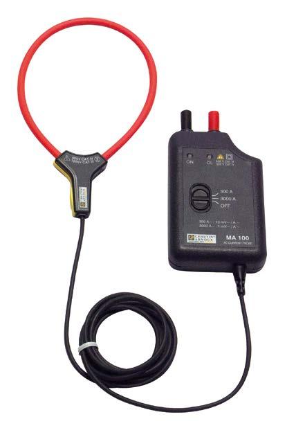
11 Measurement of AC current Selection guide Input Output - Connections Specific features Series Model Very weak current Measuring range (1) Weak current Medium current Strong current AC DC Current Voltage Lead + Ø 4 mm safety connectors (3) Ø 4 mm female sockets BNC connector (coaxial) Transformation ratio (input/output) Output protected against voltage surges Automatic DC voltage Measurement of power (slight phase shift) Bandwidth (frequency in Hz) Typical accuracy To order MA 100 MA /3 (17 cm) 0.5 A 30 A 0.5 A 300 A 3 V AC 100 mv/a 10 mv/a 1 % P MA /3 (17 cm) 0.5 A 30 A 0.5 A 300 A 3 V AC 100 mv/a 10 mv/a 1 % P MA /3 (25 cm) MA /3 (25 cm) 0.5 A 300 A 0.5 A 3000 A 0.5 A 300 A 0.5 A 3000 A 3 V AC 3 V AC 10 mv/a 1 mv/a 10 mv/a 1 mv/a 1 % P Hz 20 khz 1 % P MA /3 (35 cm) 0.5 A 300 A 0.5 A 3000 A 3 V AC 10 mv/a 1 mv/a 1 % P Chap. 7 MA /3 (35 cm) 0.5 A 300 A 0.5 A 3000 A 3 V AC 10 mv/a 1 mv/a 1 % P MA 200 MA /3 (17 cm) 0.5 A 45 A peak 0.5 A 450 A peak 4.5 V peak 100 mv/a 10 mv/a 1 % A P MA /3 (25 cm) 0.5 A 45 A peak 0.5 A 450 A peak 4.5 V peak 100 mv/a 10 mv/a 5 Hz 1 MHz 1 % A P Chap. 7 MA /3 (35 cm) 5 A 4500 A peak 4.5 V peak 1 mv/a 1 % A P A 100 Chap. 8 A /2 (45 cm) A /2 (45 cm) A /2 (80 cm) A k/2 (45 cm) A k/2 (80 cm) A k/3 (45 cm) A k/3 (80 cm) A k/3 (120 cm) A k/1 (120 cm) 0.5 A 20 A 1 A / 100 mv 2 V AC 1 % P A 200 A 1 A / 10 mv 0.5 A 2000 A 2 V AC 1 A / 1 mv 1 % P A 2000 A 2 V AC 1 A / 1 mv 1 % P A 200 A 1 A / 10 mv 2 V AC 1 % P A 2000 A 1 A / 1 mv 0.5 A 200 A 1 A / 10 mv 2 V AC 10 Hz 20 khz 1 % P A 2000 A 1 A / 1 mv 0.5 A 300 A 1 A / 10 mv 3 V AC 1 % P A 3000 A 1 A / 1 mv 0.5 A 300 A 1 A / 10 mv 3 V AC 1 % P A 3000 A 1 A / 1 mv 0.5 A 300 A 1 A / 10 mv 3 V AC 1 % P A 3000 A 1 A / 1 mv 0.5 A 1000 A 1 A / 1 mv 1 V AC 1 % P A A 1 A / 0.1 mv (1) The upper value corresponds to 120 % of the maximum rated value (3) Lead + electronic unit with Ø 4 mm safety connectors, centre distance 19 mm, for K and AmpFLEX series Ed 4 i.2 (3/3)
12 Measurement of AC/DC current Selection guide Input Output - Connections Specific features Series Model Very weak current Measuring range (1) Weak current Medium current Strong current AC DC Current Voltage Lead + Ø 4 mm safety connectors (3) Ø 4 mm female sockets BNC connector (coaxial) Transformation ratio (input/output) Output protected against voltage surges Automatic DC voltage Measurement of power (slight phase shift) Bandwidth (frequency in Hz) Typical accuracy To order 1 ma 4.5 A DC 4.5 V AC K1 1 ma 3 A RMS 3 V RMS 1 ma / 1 mv DC 2 khz 1 % P A 1 ma 4.5 A peak 4.5 V peak 100 µa 450 ma DC 4.5 V AC Chap. 9 K2 100 µa 300 ma RMS 100 µa 450 ma peak 3 V RMS 4.5 V peak 1 ma / 10 mv DC 1.5 khz 1 % P A E1N 0,05 A 2 A DC 0,05 A 1.5 A AC 0.5 A 150 A AC/DC 2 V DC 1.5 V AC 150 mv AC/ DC 1 A / 1 V 1 A / 1 mv DC 2 khz DC 8 khz 2 % 1.5 % P A E3N 0,05 A 10 A peak 1 A 100 A peak 1 V peak 1 A / 100 mv 1 A / 10 mv DC 100 khz 3 % 4 % P A Chap. 10 Chap. 11 Chap. 11 E6N PAC10 PAC11 PAC12 PAC20 PAC21 PAC22 5 ma 2 A DC 5 ma 1.5 A AC 20 ma 80 A AC/DC 0.5 A 400 A AC 0.5 A 600 A DC 0.2 A 40 A AC 0.4 A 60 A DC 0.5 A 400 A AC 0.5 A 600 A DC 0.2 A 60 A peak 0.4 A 60 A DC 0.5 A 600 A peak 0.5 A 600 A DC 0.5 A 1000 A AC 0.5 A 1400 A DC 0.2 A 100 A AC 0.4 A 150 A DC 0.5 A 1000 A AC 0.5 A 1400 A DC 0.2 A 150 A peak 0.4 A 150 A DC 0.5 A 1400 A peak 0.5 A 1400 A DC 2 V DC 1.5 V AC 0,8 V AC/ DC 1 A / 1 V 1 A / 10 mv DC 2 khz DC 8 khz 2 % 4 % P A 600 mv AC/DC 1 A / 1 mv DC 5 khz 2 % P mv AC/DC 600 mvpeak 1 A / 10 mv 1 A / 1 mv 1 A / 10 mv 1 A / 1 mv DC 10 khz DC 10 khz 1.5 % 2 % 1.5 % 2 % P P V AC/DC 1 A / 1 mv DC 5 khz 2 % P V AC/DC 1.4 V AC/DC 1.4 Vpeak 1.5 Vpeak 1 A / 10 mv 1 A / 1 mv 1 A / 10 mv 1 A / 1 mv DC 10 khz DC 10 khz 1.5 % 2.5 % 1.5 % 2.5 % P P (1) The upper value corresponds to 120 % of the maximum rated value (3) Lead + electronic unit with Ø 4 mm safety connectors, centre distance 19 mm, for K and AmpFLEX series Ed 4 i.3 (1/1)
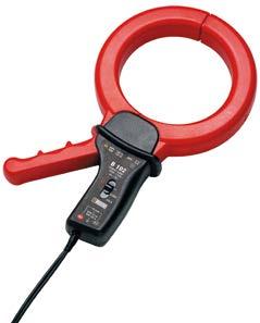
13 Selection guide Series Model Very weak current Weak current Input Output - Connections Specific features Measuring range (1) Leakage current measurement Chap. 2 Chap. 4 Chap. 6 MN73 C173 B ma 2,4 A 100 ma 240 A Medium current 1 ma 1.2A 0,01 A 12 A 0.1 A 120 A 1 A 1200 A 500 μa 4 A 0.5 A 400 A Measurement on oscilloscope Chap. 2 MN A 60 A peak 0.5 A 600 A peak Strong current AC DC Current Voltage 2 V AC 2 V AC Lead + Ø 4 mm safety connectors (3) 1 V AC 4 V AC 0.4 V AC 6 Vpeak 6 Vpeak Ø 4 mm female sockets BNC connector (coaxial) Transformation ratio (input/output) 1 A / 1000 mv 1 A / 10 mv 1 A / 1 V 10 A / 1 V 100 A / 1 V 1000 A / 1 V 1 ma / 1 mv 1 A / 1 mv 1 A / 100 mv 1 A / 10 mv Output protected against voltage surges Automatic DC voltage Measurement of power (slight phase shift) Bandwidth (frequency in Hz) 40 Hz 10 khz 10 Hz 3 khz 10 Hz 1 khz 40 Hz 40 khz Typical accuracy 1 % 2 % 0.7 % 0.3 % 0.5 % 0.2 % 0.5 % 0.35 % 2 % 1.5 % To order P P P P Chap. 3 Chap. 4 Chap. 5 Chap. 10 Chap. 7 Chap. 11 Chap. 11 Y7N 1 A 1200 A peak 1.2 Vpeak 1 ma / 1 mv 5 Hz 10 khz 2 % P C160 D38N E3N MA /3 (17 cm / Ø 4.5 cm) MA /3 (25 cm / 7 cm) MA /3 (35 cm / Ø 10 cm) PAC12 PAC22 0,05 A 10 A peak 1 A 100 A peak 0.1 A 30 A peak 1 A 300 A peak 1 A 2000 A peak 1 A 90 A peak 1 A 900 A peak 1 A 9000 A peak 0.5 A 45 A peak 0.5 A 450 A peak 0.5 A 45 A peak 0.5 A 450 A peak 3 V peak 3 V peak 2 V peak 0.9 Vpeak 1 V peak 4.5 V peak 4.5 V peak 10 A / 1 V 100 A / 1 V 1000 A / 1 V 1 A / 10 mv 1 A / 1 mv 1 A / 0.1 mv 1 A / 10 mv 1 A / 1 mv 100 mv/a 10 mv/a 100 mv/a 10 mv/a 5 A 4500 A peak 4.5 V peak 1 mv/a 0.2 A 60 A peak 0.4 A 60 A DC 0.5 A 600 A peak 0.5 A 600 A DC 0.2 A 150 A peak 0.4 A 150 A DC 0.5 A 1400 A peak 0.5 A 1400 A DC 600 mvpeak Measurement of process current Chap. 9 1 ma 4.5 A DC K1 1 ma 3 A RMS 1 ma 4.5 A peak 100 μa 450 ma DC K2 100 μa 300 ma RMS 100 μa 450 ma peak 1.5 Vpeak 1.4 Vpeak 4.5 V DC 3 V RMS 4.5 V peak 4.5 V DC 3 V RMS 4.5 V peak 1 A / 10 mv 1 A / 1 mv 1 A / 10 mv 1 A / 1 mv Measurement on secondary winding of current transformers Chap Hz 100 khz 3 % 2 % 1 % P Hz 50 khz 2 % P A DC 100 khz 5 Hz 1 MHz DC 10 khz DC 10 khz 3 % 4 % P A 1 % A P % A P % A P % 2 % 1.5 % 2.5 % P P ma / 1 mv DC 2 khz 1 % P A 1 ma / 10 mv DC 1.5 khz 1 % P A MN71 10 ma 12 A 1 V AC 1 A / 100 mv 40 Hz 10 khz 1 % P (1) The upper value corresponds to 120 % of the maximum rated value (3) Lead + electronic unit with Ø 4 mm safety connectors, centre distance 19 mm, for K and AmpFLEX series Ed 4 i.4 (1/1)

14 Current clamps for AC current MINI series MINI series Small, compact and particularly resistant, this range of miniature clamps is designed for measurements from a few milli-amperes to 150 A AC. Their shape makes them very practical in confined spaces, such as circuit-breaker boards, control panels or control boxes. They are ideal for use with multimeters. There are two types of MINI clamps. The first type operates like a traditional current transformer and provides a current output (ma) which can be used with multimeters, loggers or instruments with current calibres. The second provides a voltage output proportional to the current measured. This voltage output enables instruments with AC voltage calibres to display or store current values. There is also a model with a DC voltage output. The MINI clamps give True RMS results when used with a True RMS instrument Ed (1/2)
15 Current clamps for AC current MINI series Ø 10 mm max Ed (2/2)

16 Current clamp for AC current Model MINI 01 MINI series Calibre 150 A AC Sensitivity 1 ma / A (1000 / 1) Description Small and compact, the MINI 01 current clamp is the ideal complement for any multimeter to measure AC currents in low-power tertiary or industrial applications. If there is a current in the conductor clamped, the MINI 01 clamp is protected against overvoltages during disconnection from the measurement instrument. Main specifications (1) Calibre Measurement range Accuracy of primary current in % Phase shift Output signal 150 A 2 A 150 A 2.5 % A (load 1 Ω) 3 % A (load 10 Ω) not specified 1 ma AC / A AC (1000/ 1) (150 ma for 150 A) Output: Double-insulated cable 1.5 m long, terminated by 2 insulated elbowed male banana connectors Ø 4 mm Bandwidth: 48 Hz 500 Hz Clamping capacity: Cable Ø max 10 mm Electrical specifications Load impedance: 10 Ω Maximum currents: I < 150 A permanent from 48 Hz 500 Hz Influence of temperature: 0.2 % per 10 K Influence of adjacent conductor: 2 ma / A at 50 Hz Influence of conductor position in jaws: 0.1 % at 50/60 Hz Influence of frequency: 2 % from 65 Hz to 500 Hz Maximum output voltage (secondary open): 30 V Mechanical specifications Operating temperature: -10 C to +50 C Storage temperature: -40 C to +80 C Relative humidity for operation: From 0 to 85 % RH with a linear decrease above 35 C Operating altitude: 0 to 2,000 m Casing protection rating (leakproofing): IP40 (2) (EN Ed. 1992) Drop test: 1.5 m (IEC ) Shock resistance: 100 g / 6 ms / half-period (IEC ) Vibration resistance (3) : 5-15 Hz (1.5 mm), Hz (1 mm), Hz (0.25 mm) (IEC ) Self-extinguishing capability: casing UL94 V2 Dimensions: 130 x 37 x 25 mm Weight: approx. 180 g Colour: Black casing Safety specifications Electrical safety: Instrument with double insulation or reinforced insulation between the primary, the secondary and the grippable part located under the guard as per EN Ed. 2:2001, EN Ed & EN Ed V category III, pollution degree V category IV, pollution degree 2 Electromagnetic compatibility: CE-certified equipment compliant with standard EN (Ed. 97) + A1 (Ed. 98) + A2 (Ed. 01) - Emission: stipulations for class B equipment (domestic use). - Immunity: stipulations for equipment used intermittently on industrial sites. (1) Conditions of reference: 23 C ± 3 K, 20 C to 75 % RH, sinusoidal signal with frequency of 48 Hz to 65 Hz, distortion factor < 1 % with no DC component, external DC magnetic field < 40 A/m, no external AC magnetic field, no external conductor with circulating current, conductor centred for measurement, measurement instrument load impedance 10 Ω. (2) With clamp closed. (3) Vibrations expressed in mm peak, scanning of 1 octave/minute for 10 minutes on 3 axes. To order AC current clamp model MINI 01 with operating manual Reference P Z Ed (1/1)
17 Current clamp for AC current Model MINI 02 MINI series Calibre 100 A AC Sensitivity 1 ma / A (1000 / 1) Description The MINI 02 current clamp, whose jaws are equipped with a high-performance magnetic material and a double coil, offers excellent linearity and improved performance. Small and compact, it is ideal for measuring AC currents in low-power tertiary or industrial applications. If a current is present in the conductor being clamped, the MINI 02 clamp is protected against voltage surges when it is disconnected from the measurement instrument. Main specifications (1) Calibre Measurement range Accuracy of primary current in % (48 Hz to 10 khz) Phase shift (50 Hz to 60 Hz) Output signal 100 A 50 ma A (load 1 Ω) 50 ma.. 90 A (load 10 Ω) 1 % A (load 1 Ω) 1.5 % A (load 10 Ω) 3 (load 1 Ω) 6 (load 10 Ω) 1 ma AC / A AC (1000/ 1) (100 ma for 100 A) Output: Double-insulated cable 1.5 m long, terminated by 2 insulated elbowed male banana connectors Ø 4 mm Bandwidth: 48 Hz Hz Clamping capacity: Cable Ø max 10 mm Electrical specifications Load impedance: 100 Ω Influence of load impedance: see curves Maximum currents: I < 100 A permanent from 48 Hz 10,000 Hz Influence of temperature: 0.2 % per 10 K Influence of adjacent conductor: 2 ma / A at 50 Hz Influence of conductor position in jaws: 0.1 % at 50/60 Hz Influence of frequency: 2 % from 65 Hz to 10 khz Maximum output voltage (secondary open): 30 V Mechanical specifications Operating temperature: -10 C to +50 C Storage temperature: -40 C to +80 C Relative humidity for operation: From 0 to 85 % RH with a linear decrease above 35 C Operating altitude: 0 to 2,000 m Casing protection rating (leakproofing): IP40 (2) (EN Ed. 1992) Drop test: 1.5 m (IEC ) Shock resistance: 100 g / 6 ms / half-period (IEC ) Vibration resistance (3) : 5-15 Hz (1.5 mm), Hz (1 mm), Hz (0.25 mm) (IEC ) Self-extinguishing capability: Casing UL94 V2 Dimensions: 130 x 37 x 25 mm Weight: Approx. 180 g Colour: Black casing Safety specifications Electrical safety: Instrument with double insulation or reinforced insulation between the primary, the secondary and the grippable part located under the guard as per EN Ed. 2:2001, EN Ed & EN Ed V category III, pollution degree V category IV, pollution degree 2 Electromagnetic compatibility: CE-certified equipment compliant with standard EN (Ed. 97) + A1 (Ed. 98) + A2 (Ed. 01) - Emission: stipulations for class B equipment (domestic use). - Immunity: stipulations for equipment used intermittently on industrial sites Ed (1/2)


 Vibrations expressed in mm peak, scanning of 1 octave/minute for 10 minutes on 3 axes.")
18 Current clamp for AC current Model MINI 02 Curves at 50 Hz Typical linearity error for loads of 1, 10, 30 and 100 Ω Typical phase shift for loads of 1, 10, 30 and 100 Ω MINI series Frequency response at 10 A Typical linearity error for loads of 1, 10, 30 and 100 Ω Typical phase shift for loads of 1, 10, 30 and 100 Ω (1) Conditions of reference: 23 C ± 3 K, 20 C to 75 % RH, sinusoidal signal with frequency of 48 Hz at 10 khz, distortion factor < 1 % with no DC component, external DC magnetic field < 40 A/m, no external AC magnetic field, no external conductor with circulating current, conductor centred for measurement, measurement instrument load impedance 10 Ω. (2) With clamp closed. (3) Vibrations expressed in mm peak, scanning of 1 octave/minute for 10 minutes on 3 axes. To order AC current clamp model MINI 02 with operating manual Reference P Z Ed (2/2)

19 Current clamp for AC current Model MINI 03 MINI series Calibre Sensitivity 100 A AC 1 mv / A Description Small and compact, the MINI 03 current clamp is the ideal complement for any multimeter to measure AC currents in low-power tertiary or industrial applications. When used with an AC voltmeter, it allows you to directly read the current measured on the voltmeter. Main specifications (1) Calibre Measurement range Accuracy of primary current in % Phase shift Output signal 100 A 1 A 100 A 2 % + 50 ma not specified 1 mv AC / A AC (100 mv for 100 A) Output: Double-insulated cable 1.5 m long, terminated by 2 insulated elbowed male banana connectors Ø 4 mm Bandwidth: 48 Hz 500 Hz Clamping capacity: Cable Ø max 10 mm Electrical specifications Maximum currents: I < 150 A permanent from 48 Hz 500 Hz Influence of temperature: 0.2 % per 10 K Influence of adjacent conductor: 2 ma / A at 50 Hz Influence of conductor position in jaws: 0.1 % at 50/60 Hz Influence of frequency: 1 % from 65 Hz to 500 Hz Mechanical specifications Operating temperature: -10 C to +50 C Storage temperature: -40 C to +80 C Relative humidity for operation: from 0 to 85 % RH with a linear decrease above 35 C Operating altitude: 0 to 2,000 m Casing protection rating (leakproofing): IP40 (2) (EN Ed. 1992) Drop test: 1.5 m (IEC ) Shock resistance: 100 g / 6 ms / half-period (IEC ) Vibration resistance (3) : 5-15 Hz (1.5 mm), Hz (1 mm), Hz (0.25 mm) (IEC ) Self-extinguishing capability: Casing UL94 V2 Dimensions: 130 x 37 x 25 mm Weight: Approx. 180 g Colour: Black casing Safety specifications Electrical safety: Instrument with double insulation or reinforced insulation between the primary, the secondary and the grippable part located under the guard as per EN Ed. 2:2001, EN Ed & EN Ed V category III, pollution degree V category IV, pollution degree 2 Electromagnetic compatibility: CE-certified equipment compliant with standard EN (Ed. 97) + A1 (Ed. 98) + A2 (Ed. 01) - Emission: stipulations for class B equipment (domestic use). - Immunity: stipulations for equipment used intermittently on industrial sites. (1) Conditions of reference: 23 C ± 3 K, 20 C to 75 % RH, sinusoidal signal with frequency of 48 Hz to 65 Hz, distortion factor < 1 % with no DC component, external DC magnetic field < 40 A/m, no external AC magnetic field, no external conductor with circulating current, conductor centred for measurement, measurement instrument load impedance 10 kω. (2) With clamp closed. (3) Vibrations expressed in mm peak, scanning of 1 octave/minute for 10 minutes on 3 axes. To order AC current clamp model MINI 03 with operating manual Reference P Z Ed (1/1)

20 Current clamp for AC current Model MINI 05 MINI series Calibre 10 A AC 100 A AC Sensitivity 1 mv / ma 1 mv / A Description Small and compact, the MINI 05 current clamp is the ideal complement for any multimeter to measure AC currents in low-power tertiary or industrial applications. With its 2 calibres, it offers excellent resolution for measuring AC currents from 5 ma to 100 A. Main specifications (1) Calibre 10 A 100 A Measurement range 5 ma 10 A 1 A 100 A Accuracy of primary current in % 3 % ma 2 % + 50 ma Phase shift not specified Output signal 1 mv AC/ ma AC (10 V for 10 A) 1 mv AC / A AC (100 mv for 100 A) Output: Double-insulated cable 1.5 m long, terminated by 2 insulated elbowed male banana connectors Ø 4 mm Bandwidth: 48 Hz 500 Hz Clamping capacity: Cable Ø max 10 mm Electrical specifications Maximum currents: n 100 A calibre I < 150 A permanent from 48 Hz 500 Hz n 10 A calibre I < 15 A permanent from 48 Hz 500 Hz Influence of temperature: 0.2 % per 10 K Influence of adjacent conductor: 2 ma / A at 50 Hz Influence of conductor position in jaws: 0.1 % at 50/60 Hz Influence of frequency: n 100 A calibre: 1 % from 65 Hz to 500 Hz n 10 A calibre: 3 % from 65 Hz to 500 Hz Mechanical specifications Operating temperature: -10 C to +50 C Storage temperature: -40 C to +80 C Relative humidity for operation: from 0 to 85 % RH with a linear decrease above 35 C Operating altitude: 0 to 2,000 m Casing protection rating (leakproofing): IP40 (2) (EN Ed. 1992) Drop test: 1.5 m (IEC ) Shock resistance: 100 g / 6 ms / half-period (IEC ) Vibration resistance (3) : 5-15 Hz (1.5 mm), Hz (1 mm), Hz (0.25 mm) (IEC ) Self-extinguishing capability: casing UL94 V2 Dimensions: 130 x 37 x 25 mm Weight: Approx. 180 g Colour: Black casing Safety specifications Electrical safety: Instrument with double insulation or reinforced insulation between the primary, the secondary and the grippable part located under the guard as per EN Ed. 2:2001, EN Ed & EN Ed V category III, pollution degree V category IV, pollution degree 2 Electromagnetic compatibility: CE-certified equipment compliant with standard EN (Ed. 97) + A1 (Ed. 98) + A2 (Ed. 01) - Emission: stipulations for class B equipment (domestic use). - Immunity: stipulations for equipment used intermittently on industrial sites. (1) Conditions of reference: 23 C ± 3 K, 20 C to 75 % RH, sinusoidal signal with frequency of 48 Hz to 65 Hz, distortion factor < 1 % with no DC component, external DC magnetic field < 40 A/m, no external AC magnetic field, no external conductor with circulating current, conductor centred for measurement, measurement instrument load impedance 1 MΩ (10 A calibre) & 10 kω (100 A calibre). (2) With clamp closed. (3) Vibrations expressed in mm peak, scanning of 1 octave/minute for 10 minutes on 3 axes. To order AC current clamp model MINI 05 with operating manual Reference P Z Ed (1/1)

21 Current clamp for AC current Model MINI 09 MINI series Calibre Sensitivity 150 A AC 100 mv DC / A AC Description Small and compact, the MINI 09 current clamp is the ideal complement for any multimeter to measure AC currents in low-power tertiary or industrial applications. Its DC voltage output helps to overcome the low sensitivity of certain AC measurement instruments. Main specifications (1) Calibre 150 A Measurement range 1 A 5 A 5 A 15 A 15 A 40 A 40 A 150 A Accuracy of primary current in % 10 % A 6 % A 3 % A 4 % Phase shift not specified Output signal 100 mv DC / A AC (15 V DC for 150 A) Output: Double-insulated cable 1.5 m long, terminated by 2 insulated elbowed male banana connectors Ø 4 mm Bandwidth: 48 Hz 500 Hz Clamping capacity: Cable Ø max 10 mm Electrical specifications Maximum currents: I < 150 A permanent from 65 Hz 500 Hz Influence of temperature: 0.2 % per 10 K Influence of adjacent conductor: 2 ma / A at 50 Hz Influence of conductor position in jaws: 0.1 % at 50/60 Hz Influence of frequency: 3 % from 65 Hz to 500 Hz Mechanical specifications Operating temperature: -10 C to +50 C Storage temperature: -40 C to +80 C Relative humidity for operation: 0 to 85 % RH decreasing linearly above 35 C Operating altitude: 0 to 2,000 m Casing protection rating (leakproofing): IP40 (2) (EN Ed. 1992) Drop test: 1.5 m (IEC ) Shock resistance: 100 g / 6 ms / half-period (IEC ) Vibration resistance (3) : 5-15 Hz (1.5 mm), Hz (1 mm), Hz (0.25 mm) (IEC ) Self-extinguishing capability: Casing UL94 V2 Dimensions: 130 x 37 x 25 mm Weight: Approx. 180 g Colour: Black casing Safety specifications Electrical safety: Instrument with double insulation or reinforced insulation between the primary, the secondary and the grippable part located under the guard as per EN Ed. 2:2001, EN Ed & EN Ed V category III, pollution degree V category IV, pollution degree 2 Electromagnetic compatibility: CE-certified equipment compliant with standard EN (Ed. 97) + A1 (Ed. 98) + A2 (Ed. 01) - Emission: stipulations for class B equipment (domestic use). - Immunity: stipulations for equipment used intermittently on industrial sites. (1) Conditions of reference: 23 C ± 3 K, 20 % to 75 % RH, sinusoidal signal with frequency of 48 Hz to 65 Hz, distortion factor < 1 % with no DC component, external DC magnetic field < 40 A/m, no external AC magnetic field, no external conductor with circulating current, conductor centred for measurement, measurement instrument load impedance 50 kω. (2) With clamp closed. (3) Vibrations expressed in mm peak, scanning of 1 octave/minute for 10 minutes on 3 axes. To order AC current clamp model MINI 09 with operating manual Reference P Z Ed (1/1)

22 Current clamps for AC current MN series MN series These ergonomic mini-clamps are designed to make light work of measuring low and medium currents from 0.01 A to 240 A AC. The shape of the jaws makes hooking onto cables easy, even in areas of restrictive access. The jaws can grip conductors up to 20 mm in diameter. Depending on the particular model, they have one or two calibres. The output is via either jack sockets or a lead with 4 mm Ø plugs, hence these clamps are compatible with all multimeters and testers on the market. There are two types of MN series clamps available. The first kind operates as a current transformer (ratio 1000/1) and gives a current output (ma) for use with any tester with current calibres. The second type gives a voltage output (DC or AC depending on the model) proportional to the measured current (1, 10, 100 or 1000 mv/a). This voltage output means that, even with testers without any current calibres, it is possible to measure currents by means of the DC or AC voltage calibres. There are specific models in the MN series that have been designed with particular applications in mind such as measurement on current transformer outputs, on oscilloscopes and even of leakage currents Ed (1/2)
23 Current clamps for AC current MN series 18.5 mm 65 mm 21 mm 135 mm 34.5 mm 57 mm Ed (2/2)
24 Current clamps for AC current Models MN08 and MN09 MN series Current 200 A AC Ratio 1000 / 1 Output 1 ma / A Electrical specifications Current calibre: 0.5 A AC 240 A AC Current transformation ratio: 1000 / 1 Output signal: 1 ma AC / A AC (240 ma for 240 A) Accuracy and phase shift (1) : Primary current 0.5 A 10 A 10 A 40 A 40 A 100 A 100 A 240 A % Accuracy of output signal 3 % ma 2.5 % ma 2 % ma 1 % ma Phase shift not specified Bandwidth: 40 Hz 10 khz Crest factor: 3 for a current of 200 A rms Maximum currents: 200 A continuous for a frequency 3 khz (limitation proportional to the inverse of one third of frequency beyond) Load impedance: 10 Ω Operating voltage: 600 V rms Common mode voltage: 600 V category III and pollution degree 2 Influence of adjacent conductor: 15 ma / A at 50 Hz Influence of conductor position in jaws: 0.5 % of output signal at 50/60 Hz Load influence: Ω < 0.5 % on measurement < 0.5 on phase Influence of frequency (2) : < 3 % of output signal from 40 Hz 1 khz < 12 % of output signal from 1 khz 10 khz Influence of crest factor: < 4 % of output signal for a crest factor of 3 and current 200 of A rms Mechanical specifications Operating temperature: -10 C to +55 C Storage temperature: -40 C to +70 C Influence of temperature: 0.15 % of output signal per 10 K Relative humidity for operation: 0 to 85 % RH decreasing linearly above 35 C Influence of relative humidity: < 0.2 % of output signal from 10 % to 85 % RH Operating altitude: 0 to 2,000 m Max. jaw opening: 20 mm Clamping capacity: Cable: max 20 mm Busbar: 1 busbar of 20 x 5 mm Casing protection rating: IP40 (IEC 529) Drop test: 1 m (IEC ) Shock resistance: 100 g (IEC ) Vibration resistance: 10 / 55/10 Hz, 0.15 mm (IEC ) Self-extinguishing capability: Casing: UL94 V2 Jaws: UL94 V0 Dimensions: 135 x 51 x 30 mm Weight: 180 g Colours: Dark grey case with red jaws Output: n MN08: Safety sockets (4 mm) n MN09: 1.5 m two-wire lead with double or reinforced insulation terminated by 2 elbowed male safety plugs (4 mm) Safety specifications Electrical safety: Instrument with double insulation or reinforced insulation between the primary, the secondary and the grippable part located under the guard as per IEC & IEC V category III, pollution degree V category IV, pollution degree 2 Electromagnetic compatibility (EMC): EN : class B EN : - Electrostatic discharge: IEC Radiated field: IEC Fast transients: IEC Magnetic field at 50/60 Hz: IEC (1) Conditions of reference: 23 C ± 3 K, 20 to 70 % RH, sinusoidal signal with frequency of 48 Hz to 65 Hz, external magnetic field < 40 A/m, no DC components, no external conductor with circulating current, conductor centred for measurement, 1 Ω load. (2) Out of reference domain. To order AC current clamp model MN08 with operating manual AC current clamp model MN09 with operating manual Reference P P Ed (1/1)
25 Current clamps for AC current Models MN10 and MN11 MN series Current 200 A AC Ratio 1000 / 1 Output 1 ma / A Description An electronic voltage-limiting system protects output of clamp when operating, if the secondary circuit is opened. Electrical specifications Current calibre: 0.5 A AC 240 A AC Current transformation ratio: 1000 / 1 Output signal: 1 ma AC / A AC (240 ma for 240 A) Accuracy and phase shift (1): Primary current 0.5 A 10 A 10 A 40 A 40 A 100 A 100 A 150 A 150 A 200 A 200 A 240 A Accuracy in % of output signal 3 % ma 2.5 % ma 2 % ma 1 % ma 2 % ma 3 % ma Phase shift not specified Bandwidth: 40 Hz 10 khz Crest factor: 3 for a current of 200 A rms Maximum currents: 200 A continuous for a frequency 3 khz (limitation proportional to the inverse of one third of frequency beyond) Load impedance: 10 Ω Maximum output voltage (secondary open): Limited to 8 V peak max. Operating voltage: 600 V rms Common mode voltage: 600 V category III and pollution degree 2 Influence of adjacent conductor: 15 ma / A at 50 Hz Influence of conductor position in jaws: 0.5 % of output signal at 50/60 Hz Load influence: Ω < 0.5 % on measurement < 0.5 on phase Influence of frequency (2) : < 3 % of output signal from 40 Hz 1 khz < 12 % of output signal from 1 khz 10 khz Influence of crest factor: < 4 % of output signal for a crest factor of 3 and current of 200 A rms Mechanical specifications Operating temperature: -10 C to +55 C Storage temperature: -40 C to +70 C Influence of temperature: 0.15 % of output signal per 10 K Relative humidity for operation: 0 to 85 % RH decreasing linearly above 35 C Influence of relative humidity: < 0.2 % of output signal from 10 % to 85 % RH Operating altitude: 0 to 2,000 m Max. jaw opening: 20 mm Clamping capacity: Cable: max 20 mm Busbar: 1 busbar of 20 x 5 mm Casing protection rating: IP40 (IEC 529) Drop test: 1 m (IEC ) Shock resistance: 100 g (IEC ) Vibration resistance: 10 / 55/10 Hz, 0.15 mm (IEC ) Self-extinguishing capability: Casing: UL94 V2 Jaws: UL94 V0 Dimensions: 135 x 51 x 30 mm Weight: 180 g Colours: Dark grey case with red jaws Output: n MN10: Safety sockets (4 mm) n MN11: 1.5 m two-wire lead with double or reinforced insulation terminated by 2 elbowed male safety plugs (4 mm) Safety specifications Electrical safety: Instrument with double insulation or reinforced insulation between the primary, the secondary and the grippable part located under the guard as per IEC & IEC V category III, pollution degree V category IV, pollution degree 2 Electromagnetic compatibility (EMC): EN : class B EN : - Electrostatic discharge: IEC Radiated field: IEC Fast transients: IEC Magnetic field at 50/60 Hz: IEC (1) Conditions of reference: 23 C ± 3 K, 20 to 70 % RH, sinusoidal signal with frequency of 48 Hz to 65 Hz, external magnetic field < 40 A/m, no DC components, no external conductor with circulating current, conductor centred for measurement, 1 Ω load. (2) Out of reference domain. To order AC current clamp model MN10 with operating manual AC current clamp model MN11 with operating manual Reference P P Ed (1/1)
26 Current clamps for AC current Models MN12 and MN13 MN series Current Output 200 A AC 10 mv / A Electrical specifications Current calibre: 0.5 A AC 240 A AC Output signal: 10 mv AC / A AC (2.4 V for 240 A) Accuracy and phase shift (1) : Primary current 0.5 A 10 A 10 A 40 A 40 A 100 A 100 A 240 A % Accuracy of output signal 3.5 % + 5 mv 2.5 % + 5 mv 2 % + 5 mv 1 % + 5 mv Phase shift not specified Bandwidth: 40 Hz 10 khz Crest factor: 3 for a current of 200 A rms Maximum currents: 200 A continuous for a frequency 1 khz (derating proportional to the inverse of frequency beyond) Load impedance: > 1 MΩ Operating voltage: 600 V rms Common mode voltage: 600 V category III and pollution degree 2 Influence of adjacent conductor: 15 ma / A at 50 Hz Influence of conductor position in jaws: 0.5 % of output signal at 50/60 Hz Influence of frequency (2) : < 3 % of output signal from 40 Hz 1 khz < 12 % of output signal from 1 khz 10 khz Influence of crest factor: < 3 % of output signal for a crest factor of 3 and current of 200 A rms Mechanical specifications Operating temperature: -10 C to +55 C Storage temperature: -40 C to +70 C Influence of temperature: 0.15 % of output signal per 10 K Relative humidity for operation : 0 to 85 % RH decreasing linearly above 35 C Influence of relative humidity: < 0.2 % of output signal from 10 % to 85 % RH Operating altitude: 0 to 2,000 m Max. jaw opening: 20 mm Clamping capacity: Cable: max 20 mm Busbar: 1 busbar of 20 x 5 mm Casing protection rating: IP40 (IEC 529) Drop test: 1 m (IEC ) Shock resistance: 100 g (IEC ) Vibration resistance: 10 / 55/10 Hz, 0.15 mm (IEC ) Self-extinguishing capability: Casing: UL94 V2 Jaws: UL94 V0 Dimensions: 135 x 51 x 30 mm Weight: 180 g Colours: Dark grey case with red jaws Output: n MN12: Safety sockets (4 mm) n MN13: 1.5 m two-wire lead with double or reinforced insulation terminated by 2 elbowed male safety plugs (4 mm) Safety specifications Electrical safety: Instrument with double insulation or reinforced insulation between the primary, the secondary and the grippable part located under the guard as per IEC & IEC V category III, pollution degree V category IV, pollution degree 2 Electromagnetic compatibility (EMC): EN : class B EN : - Electrostatic discharge: IEC Radiated field: IEC Fast transients: IEC Magnetic field at 50/60 Hz: IEC (1) Conditions of reference: 23 C ± 3 K, 20 to 70 % RH, sinusoidal signal with frequency of 48 Hz to 65 Hz, external magnetic field < 40 A/m, no DC components, no external conductor with circulating current, conductor centred for measurement, load impedance > 1 MΩ. (2) Out of reference domain To order AC current clamp model MN12 with operating manual AC current clamp model MN13 with operating manual Reference P P Ed (1/1)
27 Current clamps for AC current Models MN14 and MN15 MN series Current Output 200 A AC 1 mv / A Electrical specifications Current calibre: 0.5 A AC 240 A AC Output signal: 1 mv AC / A AC (240 mv for 240 A) Accuracy and phase shift (1): Primary current 0.5 A 10 A 10 A 40 A 40 A 100 A 100 A 240 A % Accuracy of output signal 3 % + 5 mv 2.5 % + 5 mv 2 % + 5 mv 1 % + 5 mv Phase shift not specified Bandwidth: 40 Hz 10 khz Crest factor: 3 for a current of 200 A rms Maximum currents: 200 A continuous for a frequency 1 khz (limitation proportional to the inverse of frequency beyond) Load impedance: > 1 MΩ Operating voltage: 600 V rms Common mode voltage: 600 V category III and pollution degree 2 Influence of adjacent conductor: 15 ma / A at 50/60 Hz Influence of conductor position in jaws: 0.5 % of output signal at 50/60 Hz Influence of frequency (2) : < 3 % of output signal from 40 Hz 1 khz < 12 % of output signal from 1 khz 10 khz Influence of crest factor: < 3 % of output signal for a crest factor of 3 and current of 200 A rms Mechanical specifications Operating temperature: -10 C to +55 C Storage temperature: -40 C to +70 C Influence of temperature: 0.15 % of output signal per 10 K Relative humidity for operation: 0 to 85 % RH decreasing linearly above 35 C Influence of relative humidity: < 0.2 % of output signal of 10 % at 90 % RH Operating altitude: 0 to 2,000 m Max. jaw opening: 20 mm Clamping capacity: Cable: Ø max 20 mm Busbar: 1 busbar of 20 x 5 mm Casing protection rating: IP40 (IEC 529) Drop test: 1 m (IEC ) Shock resistance: 100 g (IEC ) Vibration resistance: 10 / 55/10 Hz, 0.15 mm (IEC ) Self-extinguishing capability: Casing: UL94 V2 Jaws: UL94 V0 Dimensions: 135 x 51 x 30 mm Weight: 180 g Colours: Dark grey case with red jaws Output: n MN14: Safety sockets (4 mm) n MN15: 1.5 m two-wire lead with double or reinforced insulation terminated by 2 elbowed male safety plugs (4 mm) Safety specifications Electrical safety: Instrument with double insulation or reinforced insulation between the primary, the secondary and the grippable part located under the guard as per IEC & IEC V category III, pollution degree V category IV, pollution degree 2 Electromagnetic compatibility (EMC): EN : class B EN : - Electrostatic discharge: IEC Radiated field: IEC Fast transients: IEC Magnetic field at 50 Hz: IEC (1) Conditions of reference: 23 C ± 3 K, 20 to 70 % RH, sinusoidal signal with frequency of 48 Hz to 65 Hz, external magnetic field < 40 A/m, no DC components, no external conductor with circulating current, conductor centred for measurement, load impedance > 1 MΩ. (2) Out of reference domain To order AC current clamp model MN14 with operating manual AC current clamp model MN15 with operating manual Reference P P Ed (1/1)
28 Current clamp for AC current Model MN21 MN series Current 200 A AC Ratio 1000 / 1 Output 1 ma / A Description An electronic voltage-limiting system protects output of clamp when operating, if the secondary circuit is opened. Electrical specifications Current calibre: 0.1 A AC 240 A AC Current transformation ratio: 1000 / 1 Output signal: 1 ma AC / A AC (240 ma for 240 A) Accuracy and phase shift (1) : Primary current 0.1 A 10 A 1 A 20 A 20 A 80 A 80 A 150 A 150 A 200 A % Accuracy of output signal 2 % + 20 µa 1 % + 20 µa 1 % 2 % 4 % Phase shift not specified Bandwidth: 40 Hz 10 khz Crest factor: 5 for a current of 280 A peak Maximum currents: 200 A continuous for a frequency 3 khz (limitation proportional to the inverse of one third of frequency beyond) Load impedance: 10 Ω Maximum output voltage (secondary open): Limited to 8 V peak max. Operating voltage: 600 V rms Common mode voltage: 600 V category III and pollution degree 2 Influence of adjacent conductor: 15 ma / A at 50 Hz Influence of conductor position in jaws: 0.5 % of output signal at 50/60 Hz Load influence: Ω < 0.5 % on measurement < 0.5 on phase Influence of frequency Ip < 150 A (2) : < 5 % of output signal from 40 Hz 1 khz < 15 % of output signal from 1 khz 10 khz add 5 % error if 150 A < Ip < 200 A Influence of crest factor: < 3 % of output signal for crest factor < 5 with current < 280 A peak (50 A rms) Mechanical specifications Operating temperature: -10 C to +55 C Storage temperature: -40 C to +70 C Influence of temperature: 0.20 % of output signal per 10 K Relative humidity for operation: 0 to 85 % RH decreasing linearly above 35 C Influence of relative humidity: < 0.2 % of output signal from 10 % to 85 % RH Operating altitude: 0 to 2,000 m Max. jaw opening: 20 mm Clamping capacity: Cable: Ø max 20 mm Busbar: 1 busbar of 20 x 5 mm Casing protection rating: IP40 (IEC 529) Drop test: 1 m (IEC ) Shock resistance: 100 g (IEC ) Vibration resistance: 10 / 55/10 Hz, 0.15 mm (IEC ) Self-extinguishing capability: Casing: UL94 V2 Jaws: UL94 V0 Dimensions: 135 x 51 x 30 mm Weight: 180 g Colours: Dark grey case with red jaws Output: 1.5 m two-wire lead with double or reinforced insulation terminated by 2 elbowed male safety plugs (4 mm) Safety specifications Electrical safety: Instrument with double insulation or reinforced insulation between the primary, the secondary and the grippable part located under the guard as per IEC & IEC V category III, pollution degree V category IV, pollution degree 2 Electromagnetic compatibility (EMC): EN : class B EN : - Electrostatic discharge: IEC Radiated field: IEC Fast transients: IEC Magnetic field at 50 Hz: IEC (1) Conditions of reference: 23 C ± 3 K, 20 to 70 % RH, sinusoidal signal with frequency of 48 Hz to 65 Hz, external magnetic field < 40 A/m, no DC components, no external conductor with circulating current, conductor centred for measurement, 1 Ω load. (2) Out of reference domain To order AC current clamp model MN21 with operating manual Reference P Ed (1/1)
29 Current clamp for AC current Model MN23 MN series Current Output 200 A AC 10 mv / A Electrical specifications Current calibre: 0.1 A AC 240 A AC Output signal: 10 mv AC / A AC (2.4 V for 240 A) Accuracy and phase shift (1) : Primary current 0.1 A 1 A 1 A 20 A 20 A 80 A 80 A 150 A 150 A 200 A % Accuracy of output signal 3 % µa 2 % µa 1 % 4 % 10 % Phase shift not specified Bandwidth: 40 Hz 10 khz Crest factor: 5 for a current of 280 A peak Maximum currents: 200 A continuous for a frequency 1 khz (limitation proportional to the inverse of frequency beyond) Load impedance: > 1 MΩ Operating voltage: 600 V rms Common mode voltage: 600 V category III and pollution degree 2 Influence of adjacent conductor: 15 ma / A at 50 Hz Influence of conductor position in jaws: 0.5 % of output signal at 50/60 Hz Influence of frequency at IP < 100 A (2) : < 5 % of output signal from 40 Hz 1 khz** < 15 % of output signal from 1 khz 10 khz **Add 10 % error if 100 < IP < 200 A Influence of crest factor: < 3 % of output signal for a crest factor < 5 to a current < 280 A peak (50 A rms) Mechanical specifications Operating temperature: -10 C to +55 C Storage temperature: -40 C to +70 C Influence of temperature: 0.20 % of output signal per 10 K Relative humidity for operation: 0 to 85 % RH decreasing linearly above 35 C Influence of relative humidity: < 0.2 % of output signal from 10 % to 85 % RH Operating altitude: 0 to 2,000 m Max. jaw opening: 20 mm Clamping capacity: Cable: Ø max 20 mm Busbar: 1 busbar of 20 x 5 mm Casing protection rating: IP40 (IEC 529) Drop test: 1 m (IEC ) Shock resistance: 100 g (IEC ) Vibration resistance: 10 / 55/10 Hz, 0.15 mm (IEC ) Self-extinguishing capability: Casing: UL94 V2 Jaws: UL94 V0 Dimensions: 135 x 51 x 30 mm Weight: 180 g Colours: Dark grey case with red jaws Output: 1.5 m two-wire lead with double or reinforced insulation terminated by 2 elbowed male safety plugs (4 mm) Safety specifications Electrical safety: Instrument with double insulation or reinforced insulation between the primary, the secondary and the grippable part located under the guard as per IEC & IEC ,5 V category III, pollution degree 2-306,5 V category IV, pollution degree 2 Electromagnetic compatibility (EMC): EN : class B EN : - Electrostatic discharge: IEC Radiated field: IEC Fast transients: IEC Magnetic field at 50 Hz: IEC (1) Conditions of reference: 23 C ± 3 K, 20 to 70 % RH, sinusoidal signal with frequency of 48 Hz to 65 Hz, external magnetic field < 40 A/m, no DC components, no external conductor with circulating current, conductor centred for measurement, load impedance > 1 MΩ. (2) Out of reference domain To order AC current clamp model MN23 with operating manual Reference P Ed (1/1)
30 Current clamps for AC current Models MN38 and MN39 MN series Current 20 A AC 200 A AC Output 100 mv / A 10 mv / A Electrical specifications Current calibres: 0.1 A AC 24 A AC 0.5 A AC 240 A AC Output signal: 100 mv AC / A AC (2.4 V for 24 A) 10 mv AC / A AC (2.4 V for 240 A) Accuracy and phase shift (1) : Calibre 20 A 200 A Primary current 0.1 A 20 A 0.5 A 10 A 10 A 40 A 40 A 100 A 100 A 240 A % Accuracy of output signal 1 % + 50 mv 3 % + 5 mv 2.5 % + 5 mv 2 % + 5 mv 1 % + 5 mv Phase shift not specified not specified Bandwidth: 40 Hz 10 khz Crest factor: 3 for a current of 200 A rms Maximum currents: 200 A continuous for a frequency 1 khz (limitation proportional to the inverse of frequency beyond) Load impedance: > 1 MΩ Operating voltage: 600 V rms Common mode voltage: 600 V category III and pollution degree 2 Influence of adjacent conductor: 15 ma / A at 50 Hz Influence of conductor position in jaws: 0.5 % of output signal at 50/60 Hz Influence of frequency (2) : n 20 A calibre: < 5 % of output signal from 40 Hz 1 khz < 15 % of output signal from 1 khz 10 khz n 200 A calibre: < 3 % of output signal from 40 Hz 1 khz < 12 % of output signal from 1 khz 10 khz Influence of crest factor: < 3 % of output signal for a crest factor of 3 and current of 200 A rms Mechanical specifications Operating temperature: -10 C to +55 C Storage temperature: -40 C to +70 C Influence of temperature: 0.15 % of output signal per 10 K Relative humidity for operation: 0 to 85 % RH decreasing linearly above 35 C Influence of relative humidity: < 0.2 % of output signal from 10 % to 85 % RH Operating altitude: 0 to 2,000 m Max. jaw opening: 20 mm Clamping capacity: Cable: Ø max 20 mm Busbar: 1 busbar of 20 mm x 5 mm Casing protection rating: IP40 (IEC 529) Drop test: 1 m (IEC ) Shock resistance: 100 g (IEC ) Vibration resistance: 10 / 55/10 Hz, 0.15 mm (IEC ) Self-extinguishing capability: Casing: UL94 V2 Jaws: UL94 V0 Dimensions: 135 x 51 x 30 mm Weight: 180 g Colours: Dark grey case with red jaws Output: n MN38: Safety jacks (4 mm) n MN39: 1.5 m two-wire lead with double or reinforced insulation terminated by 2 elbowed male safety plugs (4 mm) Safety specifications Electrical safety: Instrument with double insulation or reinforced insulation between the primary, the secondary and the grippable part located under the guard as per IEC & IEC V category III, pollution degree V category IV, pollution degree 2 Electromagnetic compatibility (EMC): EN : class B EN : - Electrostatic discharge: IEC Radiated field: IEC Fast transients: IEC Magnetic field at 50/60 Hz: IEC (1) Conditions of reference: 23 C ± 3 K, 20 to 70 % RH, sinusoidal signal with frequency of 48 Hz to 65 Hz, external magnetic field < 40 A/m, no DC components, no external conductor with circulating current, conductor centred for measurement, load impedance > 1 MΩ. (2) Out of reference domain To order AC current clamp model MN38 with operating manual AC current clamp model MN39 with operating manual Reference P P Ed (1/1)
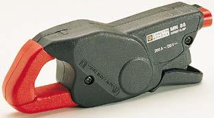
31 Oscilloscope clamp for AC current Model MN60 (insulated AC current probe) MN series Current 60 A peak 600 A peak Output 100 mv / A 10 mv / A Description This 200 A AC clamp enables easy display and measurement of current curves. It fits any oscilloscope since it has a coaxial lead with BNC plug. It produces a mv signal directly proportional to current. It offers 2 different sensitivities. Electrical specifications Current calibres: 0.1 A AC 20 A AC (60 A peak) 0.5 A AC 200 A AC (600 A peak) Output signal: 100 mv AC / A AC (2 V for 20 A) 10 mv AC / A AC (2 V for 200 A) Accuracy and phase shift (1) : Calibre 20 A 200 A Primary current 0.1 A 20 A 0.5 A 10 A 10 A 40 A 40 A 100 A 100 A 240 A Accuracy in % of output signal 2 % + 50 mv 3.5 % + 5 mv 3 % + 5 mv 2.5 % + 5 mv 1.5 % + 5 mv Phase shift not specified not specified Bandwidth: 40 Hz 40 khz (-3 db) (depending on current value) Rise/fall time from 10 % to 90 %: n 20 A calibre: 7.4 µs n 200 A calibre: 8.7 µs 10 % delay time: 0.1 µs Ampere second product: n 20 A calibre: 25 A.s n 200 A calibre: 2 A.s Insertion impedance (at 400 Hz / 10 khz) n 20 A calibre: < 0.3 mω / < 7.2 mω n 200 A calibre: < 1 mω / < 26 mω Maximum currents: 200 A continuous for a frequency 3 khz (limitation proportional to inverse of one third of frequency beyond) Influence of temperature: 150 ppm /k or 0.15 % of output signal per 10 K Influence of relative humidity: < 0.2 % of output signal Influence of adjacent conductor: 15 ma / A at 50 Hz Influence of DC current < 10 % of rated calibre superimposed on the rated current: n 20 A calibre: For I DC < 2 A: influence < 0.5 % n 200 A calibre: For I DC < 20 A: influence < 5 % Influence of conductor position in jaws: 0.5 % of output signal at 50/60 Hz Influence of frequency (2) : n 20 A calibre: < 10 % of output signal from 40 Hz 1 khz < 15 % of output signal from 1 khz 10 khz n 200 A calibre: < 3 % of output signal from 40 Hz 1 khz < 12 % of output signal from 1 khz 10 khz Influence of crest factor: < 3 % of output signal for a crest factor of 3 and current of 200 A rms Mechanical specifications Operating temperature: -10 C to +55 C Storage temperature: -40 C to +70 C Relative humidity for operation: 0 to 85 % RH decreasing linearly above 35 C Operating altitude: 0 to 2,000 m Max. jaw opening: 20 mm Clamping capacity: Cable: max 20 mm Busbar: 1 busbar of 20 x 5 mm Casing protection rating: IP40 (IEC 529) Drop test: 1 m (IEC ) Shock resistance: 100 g / 6 ms / half-period (IEC ) Protection against impacts: IK J (EN 50102) Vibration resistance: 10 / 55/10 Hz, 0.15 mm (IEC ) Self-extinguishing capability: Casing: UL94 V2 Jaws: UL94 V0 Dimensions: 128 x 49 x 28 mm Weight: 180 g Colours: Dark grey case with red jaws Output: Coaxial cable 2 m long, terminated by an insulated BNC connector Safety specifications Electrical safety: Instrument with double insulation or reinforced insulation between the primary, the secondary and the grippable part located under the guard as per IEC & IEC V category III, pollution degree V category IV, pollution degree 2 Electromagnetic compatibility (EMC): EN : class B EN : - Electrostatic discharge: IEC kv level 2 performance criterion B 8 kv in the air level 3 performance criterion B - Radiated field: IEC V/m performance criterion A - Fast transients: IEC kv level 2 performance criterion B 2 kv level 3 performance criterion B - Magnetic field at 50/60 Hz: IEC field of 400 A/m at 50 Hz: < 1 A Ed (1/4)

32 Oscilloscope clamp for AC current Model MN60 (insulated AC current probe) MN series Curves at 50 Hz 200 A calibre 20 A calibre Error on measurement Error on measurement in % Typical error FT limit Error on measurement in % Typical error FT limit Primary current in A at 50 Hz Primary current in A at 50 Hz Phase shift Typical phase FT limite 5.00 Phase shift in Primary current in A at 50 Hz Frequency response 200 A calibre 20 A calibre 5.00 E % at 10 A E % at 1 A Error on measurement in % E % at 40 A Error on measurement in % E % at 4 A Frequency in Hz Frequency in Hz Phase at 1 A Phase at 4 A Phase in Frequency in Hz Ed (2/4)
33 Oscilloscope clamp for AC current Model MN60 (insulated AC current probe) MN series Frequency response (cont.) 200 A calibre 20 A calibre 2.00 E % at 100 A 5.00 E % at 10 A 0.00 E % at 200 A 0.00 E % at 20 A Error on measurement in % Error on measurement in % Frequency in Hz Frequency in Hz Phase at 100 A Phase at 200 A Phase at 10 A Phase at 20 A Phase in Phase in Frequency in Hz Frequency in Hz Response to a square signal 200 A calibre 20 A calibre 10 A at 10 Hz 10 A at 100 Hz Ed (3/4)
34 Oscilloscope clamp for AC current Model MN60 (insulated AC current probe) MN series Response to a square signal (cont.) 200 A calibre 20 A calibre 10 A at 1 khz 10 A at 10 khz (1) Conditions of reference: 23 C ± 3 K, 20 % to 75 % RH, sinusoidal signal with frequency of 48 Hz at 1 khz, external magnetic field < 40 A/m, no DC components, no external conductor with circulating current, conductor centred for measurement, load impedance > 1 MΩ and <100 pf. (2) Out of reference domain To order AC current clamp model MN60 for oscilloscope with operating manual Reference P Ed (4/4)
35 Current clamp for AC current Model MN71 MN series Current Output 10 A AC 100 mv / A Description This clamp was specially designed to measure current on current transformer secondary circuits. Electrical specifications Current calibre: 0.01 A AC 12 A AC Output signal: 100 mv AC / A AC (1.2 V for 12 A) Accuracy and phase shift (1) : Primary current 0.01 A 0.1 A 0.1 A 1 A 1 A 5 A 5 A 12 A Accuracy in % of output signal 3 % mv 2.5 % 1 % Phase shift not specified Bandwidth: 40 Hz 10 khz Crest factor: 5 for a current of 40 A peak (8 A rms) Maximum currents: 20 A continuous for a frequency 10 khz (limitation proportional to the inverse of one tenth of frequency beyond) Load impedance: > 1 MΩ Operating voltage: 600 V rms Common mode voltage: 600 V category III and pollution degree 2 Influence of adjacent conductor: < 15 ma / A at 50 Hz Influence of conductor position in jaws: < 0.5 % of output signal at 50/60 Hz Influence of frequency (2) : < 5 % of output signal from 20 Hz 1 khz < 10 % of output signal from 1 khz 10 khz Influence of crest factor: < 3 % of output signal for crest factor < 5 with current < 40 A rms Mechanical specifications Operating temperature: -10 C to +55 C Storage temperature: -40 C to +70 C Influence of temperature: 0.2 % of output signal per 10 K Relative humidity for operation: 0 to 85 % RH decreasing linearly above 35 C Influence of relative humidity: < 0.2 % of output signal from 10 % to 85 % RH Operating altitude: 0 to 2,000 m Max. jaw opening: 20 mm Clamping capacity: Cable: max 20 mm Busbar: 1 busbar of 20 x 5 mm Casing protection rating: IP40 (IEC 529) Drop test: 1 m (IEC ) Shock resistance: 100 g (IEC ) Vibration resistance: 10 / 55/10 Hz, 0.15 mm (IEC ) Self-extinguishing capability: Casing: UL94 V2 Jaws: UL94 V0 Dimensions: 135 x 51 x 30 mm Weight: 180 g Colours: Dark grey case with red jaws Output: 1.5 m two-wire lead with double or reinforced insulation terminated by 2 elbowed male safety plugs (4 mm) Safety specifications: Electrical safety: Instrument with double insulation or reinforced insulation between the primary, the secondary and the grippable part located under the guard as per IEC & IEC V category III, pollution degree V category IV, pollution degree 2 Electromagnetic compatibility (EMC): EN : class B EN : - Electrostatic discharge: IEC Radiated field: IEC Fast transients: IEC Magnetic field at 50 Hz: IEC (1) Conditions of reference: 23 C ± 3 K, 20 % to 75 % RH, sinusoidal signal with frequency of 48 Hz to 65 Hz, external magnetic field < 40 A/m, no DC components, no external conductor with circulating current, conductor centred for measurement, load impedance > 1 MΩ. (2) Out of reference domain To order AC current clamp model MN71 with operating manual Reference P Ed (1/1)
36 Current clamp for AC current Model MN73 MN series Current 2 A AC 200 A AC Output 1000 mv / A 10 mv / A Description This clamp has a wide measurement range (up to 200 A), and it can also measure very low currents. We call it the universal probe. Electrical specifications Current calibres: 0.01 A AC 2.4 A AC 0.1 A AC 240 A AC Output signal: 1000 mv AC / A AC (2 V for 2 A) 10 mv AC / A AC (2.4 V for 240 A) Accuracy and phase shift (1) : Calibre 2 A 200 A Primary current 0.01 A 0.1 A 0.1 A 1 A 1 A 2 A 2 A 2.4 A 0.1 A 1 A 1 A 20 A 20 A 80 A 80 A 150 A 150 A 200 A % Accuracy of output signal 5 % + 2 mv 3 % + 1 mv 1 % 1 % 3 % µv 2 % µv 1 % 4 % 10 % Phase shift not specified not specified Bandwidth: 40 Hz 10 khz Crest factor: 5 for a current of 280 A peak (200 A rms) Maximum currents: 200 A continuous for a frequency 1 khz (limitation proportional to the inverse frequency beyond) Load impedance: > 1 MΩ Operating voltage: 600 V rms Common mode voltage: 600 V category III and pollution degree 2 Influence of adjacent conductor: 15 ma / A at 50 Hz Influence of conductor position in jaws: 0.5 % of output signal at 50/60 Hz Influence of frequency (2) : n 2 A calibre: < 10 % of output signal from 40 Hz 10 khz n 200 A calibre: < 5 % of output signal from 40 Hz 1 khz** < 15 % of output signal from 1 khz 10 khz ** add 10 % error if 100 A < I Primary < 200 A Influence of crest factor: < 5 % of output signal for crest factor < 5 with current < 280 A rms Mechanical specifications Operating temperature: -10 C to +55 C Storage temperature: -40 C to +70 C Influence of temperature: 0.20 % of output signal per 10 K Relative humidity for operation: 0 to 85 % RH decreasing linearly above 35 C Influence of relative humidity: < 0.2 % of output signal from 10 % to 85 % RH Operating altitude: 0 to 2,000 m Max. jaw opening: 20 mm Clamping capacity: Cable: max 20 mm Busbar: 1 busbar of 20 x 5 mm Casing protection rating: IP40 (IEC 529) Drop test: 1 m (IEC ) Shock resistance: 100 g (IEC ) Vibration resistance: 10 / 55/10 Hz, 0.15 mm (IEC ) Self-extinguishing capability: Casing: UL94 V2 Jaws: UL94 V0 Dimensions: 135 x 51 x 30 mm Weight: 180 g Colours: Dark grey case with red jaws Output: 1.5 m two-wire lead with double or reinforced insulation terminated by 2 elbowed male safety plugs (4 mm) Safety specifications Electrical safety: Instrument with double insulation or reinforced insulation between the primary, the secondary and the grippable part located under the guard as per IEC & IEC V category III, pollution degree V category IV, pollution degree 2 Electromagnetic compatibility (EMC): EN : class B EN : - Electrostatic discharge: IEC Radiated field: IEC Fast transients: IEC Magnetic field at 50 Hz: IEC (1) Conditions of reference: 23 C ± 3 K, 20 % to 75 % RH, sinusoidal signal with frequency of 48 Hz to 65 Hz, external magnetic field < 40 A/m, no DC components, no external conductor with circulating current, conductor centred for measurement, load impedance > 1 MΩ. (2) Out of reference domain To order AC current clamp model MN73 with operating manual Accessory: AN1 artificial neutral box (see capter 12) Reference P P Ed (1/1)
37 Current clamps for AC current Models MN88 and MN89 MN series Current Output 200 A AC 100 mv DC / A Description These clamps produce a DC voltage output which is very useful for multimeters whose sensitivity in V or A is too weak. Electrical specifications Current calibre: 0.5 A AC 240 A AC Output signal: 100 mv DC / A (24 V for 240 A AC) Accuracy (1) : Primary current 0.5 A 10 A 10 A 40 A 40 A 100 A 100 A 240 A Accuracy in % of output signal 5 % + 50 mv 3 % + 50 mv 2 % + 50 mv 2 % Bandwidth: 40 Hz 10 khz Crest factor: 3 for a current of 200 A rms Maximum currents: 200 A continuous for a frequency 1 Hz (derating proportional to the inverse of frequency beyond) Load impedance: > (1 MΩ + filter RC 2 s) Operating voltage: 600 V rms Common mode voltage: 600 V category III and pollution degree 2 Influence of adjacent conductor: 15 ma / A at 50 Hz Influence of conductor position in jaws: 0.5 % of output signal at 50 Hz Influence of frequency (2) : < 5 % of output signal from 40 Hz 1 khz < 12 % of output signal from 1 khz 10 khz Influence of crest factor < 3 % of output signal for a crest factor of 3 and current of 200 A rms Mechanical specifications Operating temperature: -10 C to +55 C Storage temperature: -40 C to +70 C Influence of temperature: 0.15 % of output signal per 10 K Relative humidity for operation: 0 to 85 % RH decreasing linearly above 35 C Influence of relative humidity: < 0.2 % of output signal from 10 % to 85 % RH Operating altitude: 0 to 2,000 m Max. jaw opening: 20 mm Clamping capacity: Cable: max 20 mm Busbar: 1 busbar of 20 x 5 mm Casing protection rating: IP40 (IEC 529) Drop test: 1 m (IEC ) Shock resistance: 100 g (IEC ) Vibration resistance: 10 / 55/10 Hz, 0.15 mm (IEC ) Self-extinguishing capability: Casing: UL94 V2 Jaws: UL94 V0 Dimensions: 135 x 51 x 30 mm Weight: 180 g Colours: Dark grey case with red jaws Output: n MN88: Safety sockets (4 mm) n MN89: 1.5 m two-wire lead with double or reinforced insulation terminated by 2 elbowed male safety plugs (4 mm) Safety specifications Electrical safety: Instrument with double insulation or reinforced insulation between the primary, the secondary and the grippable part located under the guard as per IEC & IEC V category III, pollution degree V category IV, pollution degree 2 Electromagnetic compatibility (EMC): EN : class B EN : - Electrostatic discharge: IEC Radiated field: IEC Fast transients: IEC Magnetic field at 50/60 Hz: IEC (1) Conditions of reference: 23 C ± 3 K, 20 to 70 % RH, sinusoidal signal with frequency of 48 Hz to 65 Hz, external magnetic field < 40 A/m, no DC components, no external conductor with circulating current, conductor centred for measurement, load impedance > 1 MΩ + filter RC 2s. (2) Out of reference domain To order AC current clamp model MN88 with operating manual AC current clamp model MN89 with operating manual Reference P P Ed (1/1)

38 Current clamps for AC current YN series Y series The Y series clamps are designed to be both rugged and versatile whilst remaining easy to use. The jaws are designed so that the clamps can be hooked onto cables or clamped onto busbars for current measurement up to 600 A AC. There are two types of Y series clamps available: The first acts as a current transformer (ratios of 100:1 or 1000:1), giving an output current that may be read by a multimeter, logger or other suitable devices with appropriate current calibres. The other kind of Y series clamp has a DC voltage output proportional to the AC current measured, allowing instruments without current calibres to measure, display and record currents on a DC voltage calibre. There is also a model available specifically for direct use with oscilloscopes Ed (1/2)
39 Current clamps for AC current YN series Cable: 30 mm Ø max Busbar: 63 x 5 mm max 2 cables: 25 mm Ø max I 195 mm 66 mm 34 mm Ed (2/2)
40 Current clamp for AC current Model Y1N YN series Current 600 A AC Ratio 1000 / 1 Output 1 ma / A Electrical specifications Current calibre: 4 A AC 600 A AC Current transformation ratio: 1000:1 Output signal: 1 ma AC / A AC Accuracy (1): Primary current 4 A 25 A 100 A 250 A 500 A 600 A (2) Accuracy in % of output signal 4.5 % ma 4.5 % 3.5 % 3 % 3 % 3 % Phase shift not specified class 3 at 1.25 VA Bandwidth: 48 Hz 1000 Hz Load impedance: 5 Ω max Overload: 700 A for 10 minutes Maximum output voltage (secondary open): Electronic protection circuit limiting voltage to 10 V peak max. Operating voltage: 600 V rms Common mode voltage: 600 V rms Influence of adjacent and parallel conductors: < 30 ma / A at 50 Hz Influence of conductor position in jaws: ±1.5 % Mechanical specifications Operating temperature: -15 C +50 C Storage temperature: -40 C +85 C Influence of temperature: < 0.1 % per 10 K Operating altitude: 0 to 2,000 m Max. jaw opening: 33 mm Clamping capacity: Cable: Ø max 30 mm Busbar: 63 x 5 mm Casing protection rating: IP20 in accordance with IEC 529 Drop test: 1.5 m (IEC ) Shock resistance: 100 g, in accordance with IEC Vibration resistance: 10 / 55/10 Hz, 0.15 mm test in accordance with IEC Self-extinguishing capability: UL94 V0 Dimensions: 66 x 195 x 34 mm Weight: 420 g Colour: Dark grey Output: 1.5 m two-wire lead with double or reinforced insulation terminated by 2 elbowed male safety plugs (4 mm) Safety specifications Electrical safety: Double or reinforced insulation between the primary and secondary circuits and the outer casing in accordance with IEC V category III, pollution degree V category IV, pollution degree 2 Electromagnetic compatibility (EMC): EN : class B EN : - Electrical discharge: IEC Radial field: IEC Fast transients: IEC Magnetic field at 50/60 Hz: IEC (1) Conditions of reference: 23 C ± 5 K, 20 % to 75 % RH, 48 Hz to 65 Hz, external magnetic field < 40 A/m, no current-carrying conductor nearby, centred test sample, load impedance 5 Ω. (2) 700 A for 10 minutes max To order AC current clamp model Y1N with operating manual Reference P A Ed (1/1)
41 Current clamp for AC current Model Y2N YN series Current 600 A AC Ratio 1000 / 1 Output 1 ma / A Electrical specifications Current calibre: 4 A AC 600 A AC Current transformation ratio: 1000:1 Output signal: 1 ma AC / A AC Accuracy (1): Primary current 4 A 25 A 100 A 250 A 500 A 600 A (2) Accuracy in % of output signal 3 % ma 3 % 1.5 % 1 % 1 % 1 % Phase shift not specified class 1 at 1.25 VA Bandwidth: 48 Hz 1000 Hz Load impedance: 5 Ω max Overload: 700 A for 10 minutes Max. voltage at output (secondary circuit open): Electronic protection circuit limiting voltage to 10 V peak max. Operating voltage: 600 V rms Common mode voltage: 600 V rms Influence of adjacent and parallel conductors: < 30 ma / A at 50 Hz Influence of conductor position in jaws: < 1 % Mechanical specifications Operating temperature: -15 C +50 C Storage temperature: -40 C +85 C Influence of temperature: < 0.1 % per 10 K Operating altitude: 0 to 2,000 m Max. jaw opening: 33 mm Clamping capacity: Cable: Ø max 30 mm Busbar: 63 x 5 mm Casing protection rating: IP20 in accordance with IEC 529 Drop test: 1.5 m (IEC ) Shock resistance: 100 g, in accordance with IEC Vibration resistance: 10 / 55/10 Hz, 0.15 mm test in accordance with IEC Self-extinguishing capability: UL94 V0 Dimensions: 66 x 195 x 34 mm Weight: 420 g Colour: Dark grey Output: 1.5 m two-wire lead with double or reinforced insulation terminated by 2 elbowed male safety plugs (4 mm) Safety specifications Electrical safety: Double or reinforced insulation between the primary and secondary circuits and the outer casing in accordance with IEC V category III, pollution degree V category IV, pollution degree 2 Electromagnetic compatibility (EMC): EN : class B EN : - Electrical discharge IEC Radial field IEC Fast transients IEC Magnetic field at 50/60 Hz IEC (1) Conditions of reference: 23 C ± 5 K, 20 % to 75 % RH, 48 Hz to 65 Hz, external magnetic field < 40 A/m, no current-carrying conductor nearby, centred test sample, load impedance 5 Ω. (2) 700 A for 10 minutes max To order AC current clamp model Y2N with operating manual Reference P A Ed (1/1)
42 Current clamp for AC current Model Y3N YN series Current 600 A AC Ratio 100 / 1 Output 10 ma / A Electrical specifications Current calibre: 4 A AC 600 A AC Current transformation ratio: 100:1 Output signal: 10 ma AC / A AC Accuracy (1) : Primary current 4 A 25 A 100 A 250 A 500 A 600 A (2) Accuracy in % of output signal 5 % + 5 ma 5 % 3 % 3 % 3 % 3 % Phase shift not specified Class 3 at 2.5 VA Bandwidth: 48 Hz 1000 Hz Load impedance: 0.1 Ω max Overload: 700 A for 10 minutes Max. voltage at output (secondary circuit open): Electronic protection circuit limiting voltage to 10 V peak max. Operating voltage: 600 V rms Common mode voltage: 30 V rms Influence of adjacent and parallel conductors: < 30 ma / A at 50 Hz Influence of conductor position in jaws: ±1 % Mechanical specifications Operating temperature: -15 C +50 C Storage temperature: -40 C +85 C Influence of temperature: < 0.1 % per 10 K Operating altitude: 0 to 2,000 m Max. jaw opening: 33 mm Clamping capacity: Cable: Ø max 30 mm Busbar: 63 x 5 mm Casing protection rating: IP20 in accordance with IEC 529 Drop test: 1.5 m (IEC ) Shock resistance: 100 g, in accordance with IEC Vibration resistance: 10 / 55/10 Hz, 0.15 mm test in accordance with IEC Self-extinguishing capability: UL94 V0 Dimensions: 66 x 195 x 34 mm Weight: 420 g Colour: Dark grey Output: 1.5 m two-wire lead with double or reinforced insulation terminated by 2 elbowed male safety plugs (4 mm) Safety specifications Electrical safety: Double or reinforced insulation between the primary and secondary circuits and the outer casing in accordance with IEC V category III, pollution degree V category IV, pollution degree 2 Electromagnetic compatibility (EMC): EN : class B EN : - Electrical discharge IEC Radial field IEC Fast transients IEC Magnetic field at 50/60 Hz IEC (1) Conditions of reference: 23 C ± 5 K, 20 % to 75 % RH, 48 Hz to 65 Hz, external magnetic field < 40 A/m, no current-carrying conductor nearby, centred test sample, load impedance 0.1 Ω. (2) 700 A for 10 minutes max. To order AC current clamp model Y3N with operating manual Reference P A Ed (1/1)
43 Current clamp for AC current Model Y4N YN series Current Output 600 A AC 1 mv DC / A AC Electrical specifications Current calibre: 4 A AC 600 A AC Output signal: 1 mv DC / A AC Accuracy (1): Primary current 2 A 25 A 100 A 250 A 500 A 600 A (2) Accuracy in % of output signal 5 % mv DC 5 % 2 % 1 % 1 % 2 % Bandwidth: 48 Hz 1000 Hz (error: add 2 % to reference) Load impedance: > 100 kω max Overload: 700 A for 10 minutes Operating voltage: 600 V rms Common mode voltage: 600 V rms Influence of adjacent and parallel conductors: < 30 ma / A at 50 Hz Influence of conductor position in jaws: ±1 % Mechanical specifications Operating temperature: -15 C +50 C Storage temperature: -40 C +85 C Influence of temperature: < 0.1 % per 10 K Operating altitude: 0 to 2,000 m Max. jaw opening: 33 mm Clamping capacity: Cable: Ø max 30 mm Busbar: 63 x 5 mm Casing protection rating: IP20 in accordance with IEC 529 Drop test: 1.5 m (IEC ) Shock resistance: 100 g, in accordance with IEC Vibration resistance: 10 / 55/10 Hz, 0.15 mm test in accordance with IEC Self-extinguishing capability: UL94 V0 Dimensions: 66 x 195 x 34 mm Weight: 420 g Colour: Dark grey Output: 1.5 m two-wire lead with double or reinforced insulation terminated by 2 elbowed male safety plugs (4 mm) Safety specifications Electrical safety: Double or reinforced insulation between the primary and secondary circuits and the outer casing in accordance with IEC V category III, pollution degree V category IV, pollution degree 2 Electromagnetic compatibility (EMC): EN : class B EN : - Electrical discharge: IEC Radial field: IEC Fast transients: IEC Magnetic field at 50/60 Hz: IEC (1) Conditions of reference: 23 C ± 5 K, 20 % to 75 % RH, 48 Hz to 65 Hz, external magnetic field < 40 A/m, no current-carrying conductor nearby, centred test sample, load impedance 10 MΩ. (2) 600 A for 10 minutes max To order AC current clamp model Y4N with operating manual Reference P A Ed (1/1)
44 Oscilloscope clamp for AC current Model Y7N (insulated AC current probe) YN series Current Output 1200 A peak 1 mv / A Description This 500 A AC clamp can be used for the display and measurement of current curves. It comes with a coaxial cable terminated by a BNC plug, thus making it the ideal tool for use with oscilloscopes. It supplies a mv output signal that is directly proportional to the measured current. Electrical specifications Current calibre: 1 A AC 500 A AC (1200 A peak) Output signal: 1 mv AC / A AC (0.5 V for 500 A) Accuracy and phase shift (1) : Primary current 1 A 20 A 20 A 100 A 100 A 500 A Accuracy in % of output signal 5 % mv 5 % 2 % Phase shift not specified 3 1 Bandwidth: 5 Hz 10 khz (to -3 db) (depending on current) Rise/fall time from 10 % to 90 %: 37 µs 10 % delay time: 1 µs Ampere second product: 10 A.s Insertion impedance (at 400 Hz / 10 khz): < 0.1 mω / < 3.1 mω dv / dt: 0.24 mv / µs (typical) Maximum currents: 500 A constant 700 A: 10 minutes operation / 30 minutes shutdown for frequency 2 khz (limitation proportional to the inverse of one third of the frequency above that) Load impedance interne: 100 Ω / 4.7 nf Influence of temperature: 0.15 % of output signal per 10 K Influence of adjacent conductor: 5 µv / A at 50 Hz Influence of conductor position in jaws: 1.5 % A AC Mechanical specifications Operating temperature: -25 C to +50 C Storage temperature: -40 C to +80 C Relative humidity for operation: 0 to 85 % RH decreasing linearly above 35 C Operating altitude: 0 to 2,000 m Max. jaw opening: 33 mm Clamping capacity: Cable: max 30 mm Busbar: 1 busbar of 63 x 5 mm Casing protection rating: IP20 (IEC 529) Drop test: 1.5 m (IEC ) Shock resistance: 100 g / 6 ms / half-period (IEC ) Protection against impacts: IK J (EN 50102) Vibration resistance: 10 / 55/10 Hz 0.15 mm (IEC ) Self-extinguishing capability: UL94 V0 Dimensions: 195 x 66 x 34 mm Weight: 420 g Colour: Dark grey Output: Via 2 m coaxial cable terminated by insulated BNC plug Safety specifications Electrical safety: Instrument with double insulation or reinforced insulation between the primary, the secondary and the grippable part located under the guard as per IEC & IEC V category III, pollution degree V category IV, pollution degree 2 Electromagnetic compatibility (EMC): EN : class B EN : - Electrostatic discharge: IEC kv level 2 performance criterion B 8 kv in the air level 3 performance criterion B - Radiated field: IEC V/m performance criterion A - Fast transients: IEC kv level 2 performance criterion B 2 kv level 3 performance criterion B - Magnetic field at 50/60 Hz: IEC field of 400 A/m at 50 Hz: < 1 A Ed (1/3)


 * 2 / F(kHz) to calculate the maximum")
45 Oscilloscope clamp for AC current Model Y7N (insulated AC current probe) YN series Curves Error on measurement at 50 Hz Phase shift at 50 Hz YN CLAMP error phase Current In Amps Frequency response Phase shift according to frequency error in % Current A AC phase in Current A AC Frequency Frequency in HZ Influence of frequency and derating Influence of DC current Frequency Hz 5 Hz to 10 Hz 10 Hz to 20 Hz 20 Hz to 45 Hz 65 Hz to 3 khz 3 khz to 6 khz 6 khz to 10 khz 1 A to 200 A 15 % > 200 A not spec. 1 A to 300 A 5 % 300 A to 400 A 15 % 400 A to 500 A 25 % 1 A to 500 A 5 % 1 A to 50 A 5 % A 50 A to 500 A 5 % > 500 A not spec. 1 A to 100 A 15 % A > 100 A not spec. DC current In Amps 1 A to 50 A -3 db > 50 A not spec. - Error in % of reading; not spec. means not specified - Do not exceed 500 A for measurement with constant operation, and for the derating, use the formula 500(A) * 2 / F(kHz) to calculate the maximum current in A AC, in constant use, depending on the frequency in khz Ed (2/3)
 YN series Response to a square signal 5 A")
 Conditions of reference: 23 C ± 3 K, 20 % to")


46 Oscilloscope clamp for AC current Model Y7N (insulated AC current probe) YN series Response to a square signal 5 A at 10 Hz 5 A at 50 Hz 5 A at 500 Hz 5 A at 4 khz Response to a step (1) Conditions of reference: 23 C ± 3 K, 20 % to 75 % RH, sinusoidal signal with frequency of 48 Hz at 1 khz, external magnetic field < 40 A/m, no DC components, no external conductor with circulating current, conductor centred for measurement, load impedance >1 MΩ / < 100 pf. To order AC current clamp model Y7N for oscilloscope with operating manual Reference P Ed (3/3)

47 Current clamps for AC current C100 series "C100" series The "C100" series is a range of thirteen transformer clamps with all the advantages of our old "C30" series clamps whilst incorporating considerable improvements, particularly in the field of safety, ergonomics and performance: n 1000 A measurement, excellent metrology, high accuracy, high level of linearity, symmetrical coil windings for minimum phase shift, pendular adjusting system for magnetic elements, maximum conductor diameter Ø 52 mm and also some models with µ metal core specially made for wattmeter use. n Innovative design: excellent ergonomics, handle with finger grips, assisted opening system for jaws (patented system). n IEC V cat. III safety (industry and services), antislip protection, conductor anti-pinching system,... All this technology and manufacturing quality has been combined to provide the best measurement possible without any complications. A "C100" series clamp is compatible with any instrument (multimeter, wattmeter, recorder, oscilloscope...) for safe measurement of AC currents without shutting down the installation Ed (1/2)
48 Current clamps for AC current C100 series Ed (2/2)
49 Current clamp for AC current Model C100 C100 series Current 1000 A Ratio 1000 / 1 Output 1 ma / A Electrical specifications Current calibre: 0.1 A AC 1200 A AC Current transformation ratio: 1000:1 Output signal: 1 ma AC / A AC (1 A to 1000 A) Accuracy and phase shift (1) : Primary current 0.1 A 10 A 10 A 50 A (2) 200 A ( 2) 1000 A (2) 1200 A (2) Accuracy in % of output signal 3 % ma 3 % 1.5 % 0.75 % 0.5 % 0.5 % Phase shift not specified Bandwidth: 30 Hz 10 khz (-3 db) Crest factor: 6 for a current 3000 A peak (500 A rms) Maximum currents: 1000 A continuous for a frequency 1 khz (limitation proportional to the inverse frequency beyond) 1200 A for 40 minutes max. (interval between measurements > 20 minutes) Load impedance: 15 Ω Operating voltage: 600 V rms Common mode voltage: 600 V category III and pollution degree 2 Influence of adjacent conductor: 1 ma / A at 50 Hz Influence of conductor position in jaws: 0.1 % of output signal for frequencies 400 Hz Load influence: from 5 Ω to 15 Ω < 0.5 % on measurement < 0.5 on phase Influence of frequency (3) : < 1 % of output signal from 30 Hz 48 Hz < 0.5 % of output signal from 65 Hz 1 khz < 1 % of output signal from 1 khz 5 khz Influence of crest factor: < 1 % of output signal for crest factor 6 with current 3000 A peak (500 A rms) Influence of DC current superimposed on rated current: < 1 % of output signal for a current 30 A DC Mechanical specifications Operating temperature: -10 C to +50 C Storage temperature: -40 C to +70 C Influence of temperature: 0.1 % of output signal per 10 K Relative humidity for operation: 0 to 85 % RH decreasing linearly above 35 C Influence of relative humidity: < 0.1 % of output signal from 10 % to 85 % RH Operating altitude: 0 to 2,000 m Max. jaw opening: 53 mm Patented progressive opening system Clamping capacity: Cable: max 52 mm Busbar: 1 busbar of 50 x 5 mm / 4 busbars of 30 x 5 mm Casing protection rating: IP40 (IEC 529) Drop test: 1 m (IEC ) Shock resistance: 100 g (IEC ) Vibration resistance: 5/15 Hz 1.5 mm 15/25 Hz 1 mm 25/55 Hz 0.25 mm (IEC ) Self-extinguishing capability: Casing and jaws: UL94 V0 Dimensions: 216 x 111 x 45 mm Weight: 550 g Colours: Dark grey case with red jaws Output: Safety sockets (4 mm) Safety specifications Electrical safety: Instrument with double insulation or reinforced insulation between the primary, the secondary and the grippable part located under the guard as per IEC & IEC V category III, pollution degree V category IV, pollution degree 2 Electromagnetic compatibility (EMC): EN : class B EN : - Electrostatic discharge: IEC Radiated field: IEC Fast transients: IEC Magnetic field at 50/60 Hz: IEC (1) Conditions of reference: 23 C ± 3 K, 20 % to 75 % RH, sine signal, frequency of 48 Hz to 65 Hz, distortion factor < 1 %, no DC components, external magnetic field < 40 A/m, no AC magnetic field, conductor centred for measurement, load impedance 5 Ω (5 VA) (2) Accuracy class in accordance with IEC 185: 5 VA - class Hz 65 Hz (3) Out of frequency domain To order AC current clamp model C100 with operating manual Reference P Ed (1/1)
50 Current clamps for AC current Models C102 and C103 C100 series Current 1000 A Ratio 1000 / 1 Output 1 ma / A Description An electronic voltage limiter protects the output of the clamp, if the secondary circuit is opened accidentally. Electrical specifications Current calibre: 0.1 A AC 1200 A AC Current transformation ratio: 1000:1 Output signal: 1 ma AC / A AC (1 A for 1000 A) Accuracy and phase shift (1) : Primary current 0.1 A 10 A 10 A 50 A (2) 200 A ( 2) 1000 A (2) 1200 A (2) Accuracy in % of output signal 3 % ma 3 % 1.5 % 0.75 % 0.5 % 0.5 % Phase shift not specified Bandwidth: 30 Hz 10 khz (-3 db) Crest factor: 6 for a current 3000 A peak (500 A rms) Maximum currents: 1000 A continuous for a frequency 1 khz (limitation proportional to the inverse frequency beyond) 1200 A for 40 minutes max. (interval between measurements > 20 minutes) Load impedance: 15 Ω Max. voltage output: Electronic limiter 30 V max. peak Operating voltage: 600 V rms Common mode voltage: 600 V category III and pollution degree 2 Influence of adjacent conductor: 1 ma / A at 50 Hz Influence of conductor position in jaws: 0.1 % of output signal for frequencies 400 Hz Load influence: from 5 Ω to 15 Ω < 0.5 % on measurement < 0.5 on phase Influence of frequency (3) : < 1 % of output signal from 30 Hz 48 Hz < 0.5 % of output signal from 65 Hz 1 khz < 1 % of output signal from 1 khz 5 khz Influence of crest factor: < 1 % of output signal for crest factor 6 with current 3000 A peak (500 A rms) Influence of DC current superimposed on rated current: < 1 % of output signal for a current 30 A DC Mechanical specifications Operating temperature: -10 C to +50 C Storage temperature: -40 C to +70 C Influence of temperature: 0.1 % of output signal per 10 K Relative humidity for operation: 0 to 85 % RH with a linear decrease above 35 C Influence of relative humidity: < 0.1 % of output signal from 10 % to 85 % RH Operating altitude: 0 to 2,000 m Max. jaw opening: 53 mm, patented progressive opening system Clamping capacity: Cable: max 52 mm Busbar: 1 busbar of 50 x 5 mm / 4 busbars of 30 x 5 mm Casing protection rating: IP40 (IEC 529) Drop test: 1 m (IEC ) Shock resistance: 100 g (IEC ) Vibration resistance: 5/15 Hz 1.5 mm -15/25 Hz 1 mm - 25/55 Hz 0.25 mm (IEC ) Self-extinguishing capability: Casing and jaws: UL94 V0 Dimensions: 216 x 111 x 45 mm Weight: 550 g Colours: Dark grey case with red jaws Output: n C102: safety sockets (4 mm) n C103: two-wire cable with reinforced insulation or double insulation, length 1.5 m, terminated by 2 insulated elbowed male banana plugs, Ø 4 mm Safety specifications Electrical safety: Instrument with double insulation or reinforced insulation between the primary, the secondary and the grippable part located under the guard as per IEC & IEC V category III, pollution degree V category IV, pollution degree 2 Electromagnetic compatibility (EMC): EN : class B EN : - Electrostatic discharge: IEC Radiated field: IEC Fast transients: IEC Magnetic field at 50/60 Hz: IEC (1) Conditions of reference: 23 C ± 3 K, 20 % to 75 % RH, sine signal, frequency of 48 Hz to 65 Hz, distortion factor < 1 %, no DC components, external magnetic field < 40 A/m, no AC magnetic field, conductor centred for measurement, load impedance 5 Ω (5 VA). (2) Accuracy class in accordance with IEC 185: 5 VA - class Hz. (3) Out of reference domain. To order AC current clamp model C102 with operating manual AC current clamp model C103 with operating manual Reference P P Ed (1/1)
51 Current clamps for AC current Models C106 and C107 C100 series Current Output 1000 A 1 mv / A Electrical specifications Current calibre: 0.1 A AC 1200 A AC Output signal: 1 mv AC / A AC (1 V for 1000 A) Accuracy and phase shift (1): Primary current 0.1 A 10 A 10 A 50 A 200 A 1000 A 1200 A % Accuracy of output signal 3 % mv 3 % 1.5 % 0.75 % 0.5 % 0.5 % Phase shift not specified Bandwidth: 30 Hz 10 khz Crest factor: 6 for a current 3000 A peak (500 A rms) Maximum currents: 1000 A continuous for a frequency 1 khz (limitation proportional to the inverse frequency beyond) 1200 A for 40 minutes max. (interval between measurements > 20 minutes) Output impedance: 1 Ω ± 1 % Load impedance: 1 MΩ and 100 pf Operating voltage: 600 V rms Common mode voltage: 600 V category III and pollution degree 2 Influence of adjacent conductor: 1 µv / A at 50 Hz Influence of conductor position in jaws: 0.1 % of output signal for frequencies 400 Hz Load influence: On receiver, for an input impedance of 100 Ω: 1 % on measurement, no measurement on phase. On receiver, for an input impedance of 1 kω: 0.1 % on measurement, no measurement on phase Influence of frequency (2) : < 1 % of output signal from 30 Hz 48 Hz < 0.5 % of output signal from 65 Hz 1 khz < 1 % of output signal from 1 khz 5 khz Influence of crest factor: < 1 % of output signal for crest factor 6 with current 3000 A peak (500 A rms) Influence of DC current superimposed on rated current: < 1 % of output signal for a current 30 A DC Mechanical specifications Operating temperature: -10 C to +50 C Storage temperature: -40 C to +70 C Influence of temperature: 0.1 % of output signal per 10 K Relative humidity for operation: 0 to 85 % RH decreasing linearly above 35 C Influence of relative humidity: < 0.1 % of output signal from 10 % to 85 % RH Operating altitude: 0 to 2,000 m Max. jaw opening: 53 mm Patented progressive opening system Clamping capacity: Cable: max 52 mm Busbar: 1 busbar of 50 x 5 mm / 4 busbars of 30 x 5 mm Casing protection rating: IP40 (IEC 529) Drop test: 1 m (IEC ) Shock resistance: 100 g (IEC ) Vibration resistance: 5/15 Hz 1.5 mm 15/25 Hz 1 mm 25/55 Hz 0.25 mm (IEC ) Self-extinguishing capability: Casing and jaws: UL94 V0 Dimensions: 216 x 111 x 45 mm Weight: 550 g Colours: Dark grey case with red jaws Output: n C106: safety sockets (4 mm) n C107: two-wire cable with reinforced insulation or double insulation, length 1.5 m, terminated by 2 insulated elbowed male banana plugs, Ø 4 mm Safety specifications Electrical safety: Instrument with double insulation or reinforced insulation between the primary, the secondary and the grippable part located under the guard as per IEC & IEC V category III, pollution degree V category IV, pollution degree 2 Electromagnetic compatibility (EMC): EN : class B EN : - Electrostatic discharge: IEC Radiated field: IEC Fast transients: IEC Magnetic field at 50/60 Hz: IEC (1) Conditions of reference: 23 C ± 3 K, 20 % to 75 % RH, sine signal, frequency of 48 Hz to 65 Hz, distortion factor < 1 %, no DC components, external magnetic field < 40 A/m, no AC magnetic field, conductor centred for measurement. (2) Out of reference domain. To order AC current clamp model C106 with operating manual AC current clamp model C107 with operating manual Reference P P Ed (1/1)
52 Current clamps for AC current Models C112 and C113 C100 series Current Description 1000 A Ratio 1000 / 1 Output 1 ma / A Thanks to their excellent technical performance (phase shift and linearity), these µ-metal core clamps are highly recommended for wattmeter use. These clamps are protected at output against overvoltages. Electrical specifications Current calibre: A AC 1200 A AC Current transformation ratio: 1000:1 Output signal: 1 ma AC / A AC (1 A for 1000 A) Accuracy and phase shift (1) : Primary current 0.1 A 100 ma 0.1 A 1 A 1 A 10 A 10 A 100 A 100 A 1200 A % Accuracy of output signal 3 % + 5 µa 2 % + 3 µa 1 % 0.5 % 0.3 % Phase shift not specified not specified Bandwidth: 30 Hz 10 khz Crest factor: 6 for a current 2000 A peak (300 A rms) Maximum currents: 1000 A continuous for a frequency 1 khz (limitation proportional to the inverse frequency beyond) 1200 A for 40 minutes max. (interval between measurements > 20 minutes) Load impedance: 1 Ω Max. voltage output: Electronic limiter 30 V max. peak Operating voltage: 600 V rms Common mode voltage: 600 V category III and pollution degree 2 Influence of adjacent conductor: 0.5 ma / A at 50 Hz Influence of conductor position in jaws: 0.1 % of output signal for frequencies 400 Hz Load influence: from 1 Ω to 5 Ω < 0.1 % on measurement < 0.2 on phase Influence of frequency (2) : < 0.5 % of output signal from 30 Hz 48 Hz < 1 % of output signal from 65 Hz 1 khz < 2 % of output signal from 1 khz 5 khz Influence of crest factor: < 1 % of output signal for crest factor 6 with current 2000 A peak (300 A rms) Influence of DC current superimposed on rated current: < 1 % of output signal for a current 15 A DC Mechanical specifications Operating temperature: -10 C to +50 C Storage temperature: -40 C to +70 C Influence of temperature: 0.2 % of output signal per 10 K Relative humidity for operation: 0 to 85 % RH with a linear decrease above 35 C Influence of relative humidity: < 0.1 % of output signal from 10 % to 85 % RH Operating altitude: 0 to 2,000 m Max. jaw opening: 53 mm, patented progressive opening system Clamping capacity: Cable: max 52 mm Busbar: 1 busbar of 50 x 5 mm / 4 busbars of 30 x 5 mm Casing protection rating: IP40 (IEC 529) Drop test: 1 m (IEC ) Shock resistance: 100 g (IEC ) Vibration resistance: 5/15 Hz 1.5 mm, 15/25 Hz 1 mm, 25/55 Hz 0.25 mm (IEC ) Self-extinguishing capability: Casing and jaws: UL94 V0 Dimensions: 216 x 111 x 45 mm Weight: 550 g Colours: Dark grey case with red jaws Output: n C112: safety sockets (4 mm) n C113: two-wire cable with reinforced insulation or double insulation, length 1.5 m, terminated by 2 insulated elbowed male banana plugs, Ø 4 mm Safety specifications Electrical safety: Instrument with double insulation or reinforced insulation between the primary, the secondary and the grippable part located under the guard as per IEC & IEC V category III, pollution degree V category IV, pollution degree 2 Electromagnetic compatibility (EMC): EN : class B EN : - Electrostatic discharge: IEC Radiated field: IEC Fast transients: IEC Magnetic field at 50/60 Hz: IEC (1) Conditions of reference: 23 C ± 3 K, 20 % to 75 % RH, sine signal, frequency of 48 Hz to 65 Hz, distortion factor < 1 %, no DC components, external magnetic field < 40 A/m, no AC magnetic field, conductor centred for measurement, 1 Ω load (1 VA) (2) Out of reference domain. To order AC current clamp model C112 with operating manual AC current clamp model C113 with operating manual Reference P P Ed (1/1)
53 Current clamps for AC current Models C116 and C117 C100 series Current Output 1000 A 1 mv / A Description Thanks to their excellent technical performance (phase shift and linearity), these µ-metal core clamps are highly recommended for wattmeter use. Electrical specifications Current calibre: A AC 1200 A AC Output signal: 1 mv AC / A AC (1 V for 1000 A) Accuracy and phase shift (1) : Primary current 1 ma 100 ma 0.1 A 1 A 1 A 10 A 10 A 100 A 100 A 1200 A Accuracy in % of output signal 3 % + 5 µa 2 % + 3 µa 1 % 0.5 % 0.3 % Phase shift not specified not specified Bandwidth: 30 Hz 10 khz Crest factor: 6 for a current 2000 A peak (300 A rms) Maximum currents: 1000 A continuous for a frequency 1 khz (limitation proportional to the inverse frequency beyond) 1200 A for 40 minutes max. (interval between measurements > 20 minutes) Output impedance: 1 Ω ± 1 % Load impedance: 1 MΩ and 100 pf Operating voltage: 600 V rms Common mode voltage: 600 V category III and pollution degree 2 Influence of adjacent conductor: 0.5 ma / A at 50 Hz Influence of conductor position in jaws: 0.1 % of output signal for frequencies 400 Hz Load influence: On receiver, for an input impedance of 100 Ω: 1 % on measurement, no measurement on phase On receiver, for an input impedance of 1 kω: 0.1 % on measurement, no measurement on phase Influence of frequency (2) : < 0.5 % of output signal from 30 Hz 48 Hz < 1 % of output signal from 65 Hz 1 khz < 2 % of output signal from 1 khz 5 khz Influence of crest factor: < 1 % of output signal for crest factor 6 with current 2000 A peak Influence of DC current superimposed on rated current: < 1 % of output signal for a current 15 A DC Mechanical specifications Operating temperature: -10 C to +50 C Storage temperature: 40 C to +70 C Influence of temperature: 0.2 % of output signal per 10 K Relative humidity for operation: 0 to 85 % RH decreasing linearly above 35 C Influence of relative humidity: < 0.1 % of output signal from 10 % to 85 % RH Operating altitude: 0 to 2,000 m Max. jaw opening: 53 mm, patented progressive opening system Clamping capacity: Cable: max 52 mm Busbar: 1 busbar of 50 x 5 mm / 4 busbars of 30 x 5 mm Casing protection rating: IP40 (IEC 529) Drop test: 1 m (IEC ) Shock resistance: 100 g (IEC ) Vibration resistance: 5/15 Hz 1.5 mm 15/25 Hz 1 mm 25/55 Hz 0.25 mm (IEC ) Self-extinguishing capability: Casing and jaws: UL94 V0 Dimensions: 216 x 111 x 45 mm Weight: 550 g Colours: Dark grey case with red jaws Output: n C116: safety sockets (4 mm) n C117: two-wire cable with reinforced insulation or double insulation, length 1.5 m, terminated by 2 insulated elbowed male banana plugs, Ø 4 mm Safety specifications Electrical safety: Instrument with double insulation or reinforced insulation between the primary, the secondary and the grippable part located under the guard as per IEC & IEC V category III, pollution degree V category IV, pollution degree 2 Electromagnetic compatibility (EMC): EN : class B EN : - Electrostatic discharge: IEC Radiated field: IEC Fast transients: IEC Magnetic field at 50/60 Hz: IEC (1) Conditions of reference: 23 C ± 3 K, 20 % to 75 % RH, sine signal, frequency of 48 Hz to 65 Hz, distortion factor < 1 %, no DC components, external magnetic field < 40 A/m, no AC magnetic field, conductor centred for measurement, load impedance 1 MΩ and 100 pf (2) Out of reference domain To order AC current clamp model C116 with operating manual AC current clamp model C117 with operating manual Reference P P Ed (1/1)
54 Clamp-on ammeter for AC current Model C122 C100 series Current 1000 A Ratio 1000 / 5 Output 5 ma / A Description An electronic voltage-limiting system protects output of clamp when operating, if the secondary circuit is opened accidentally. Electrical specifications Current calibre: 1 A AC 1200 A AC Current transformation ratio: 1000:5 Output signal: 5 ma AC / A AC (5 A for 1000 A) Accuracy and phase shift (1) : Primary current 1 A 20 A 20 A 50 A (2) 200 A (2) 1000 A (2) 1200 A (2) Accuracy in % 6 % ma 5 % 3 % 1.5 % 1 % 1 % Phase shift not specified Bandwidth: 30 Hz 10 khz Crest factor: 6 for a current 3000 A peak (500 A rms) Maximum currents: 1000 A continuous for a frequency 1 khz (limitation proportional to the inverse frequency beyond) 1200 A for 30 minutes max (interval between measurements > 15 minutes) Load impedance: 0.6 Ω Impedance of connection leads: 40 mω Max. voltage at output (secondary circuit open): Electronic limiter 30 V max. peak Operating voltage: 600 V rms Common mode voltage: 600 V category III and pollution degree 2 Influence of adjacent conductor: 1 ma / A at 50 Hz Influence of conductor position in jaws: 0.2 % of output signal for frequencies 400 Hz Load influence: from 0.2 Ω to 0.6 Ω < 0.5 % on measurement < 0.5 on phase Influence of frequency (3) : < 1 % of output signal from 30 Hz 48 Hz < 0.5 % of output signal from 65 Hz 1 khz < 1 % of output signal from 1 khz 5 khz Influence of crest factor: < 1 % of output signal for crest factor 6 with current 3000 A peak (500 A rms) Influence of DC current superimposed on rated current: < 1 % of output signal for a current 30 A DC Mechanical specifications Operating temperature: -10 C to +50 C Storage temperature: -40 C to +70 C Influence of temperature: 0.1 % of output signal per 10 K Relative humidity for operation: 0 to 85 % RH with a linear decrease above 35 C Influence of relative humidity: < 0.2 % of output signal from 10 % to 85 % RH Operating altitude: 0 to 2,000 m Max. jaw opening: 53 mm, patented progressive opening system Clamping capacity: - Cable: max 52 mm - Busbar: 1 busbar of 50 x 5 mm / 4 busbars of 30 x 5 mm Casing protection rating: IP40 (IEC 529) Drop test: 1 m (IEC ) Shock resistance: 100 g (IEC ) Vibration resistance: 5/15 Hz 1.5 mm 15/25 Hz 1 mm 25/55 Hz 0.25 mm (IEC ) Self-extinguishing capability: Casing and jaws: UL94 V0 Dimensions: 216 x 111 x 45 mm Weight: 550 g Colours: Dark grey case with red jaws Output: Safety sockets (4 mm) Safety specifications Electrical safety: Instrument with double insulation or reinforced insulation between the primary, the secondary and the grippable part located under the guard as per IEC & IEC V category III, pollution degree V category IV, pollution degree 2 Electromagnetic compatibility (EMC): EN : class B EN : - Electrostatic discharge: IEC Radiated field: IEC Fast transients: IEC Magnetic field at 50/60 Hz: IEC (1) Conditions of reference: 23 C ± 3 K, 20 % to 75 % RH, sine signal, frequency of 48 Hz to 65 Hz, distortion factor < 1 %, no DC components, external magnetic field < 40 A/m, no AC magnetic field, conductor centred for measurement, load impedance 0.2 Ω (5 VA) (2) Accuracy class in accordance with IEC 185: 5 VA - class Hz (3) Out of reference domain To order AC current clamp model C122 with operating manual Reference P Ed (1/1)
55 Current clamp for AC current Model C148 C100 series Current 250 A AC 500 A AC 1000 A AC Ratio 250:5 500:5 1000:5 Output 20 ma / A 10 ma / A 5 ma / A Description An electronic voltage-limiting system protects output of clamp when operating if the secondary circuit is opened accidentally. Electrical specifications Current calibres: 1 A AC 300 A AC 1 A AC 600 A AC 1 A AC 1200 A AC Current transformation ratio 250:5 500:5 1000:5 Output signal: 20 ma AC / A AC (5 A for 250 A) 10 ma AC / A AC (5 A for 500 A) 5 ma AC / A AC (5 A for 1000 A) Accuracy and phase shift (1) : n 250 A calibre Primary current 1 A 5 A 5 A 12.5 A (2) 50 A (2) 250 A (2) 300 A (2) Accuracy in % 10 % + 2 ma 10 % 5 % 2.5 % 2 % 2 % Phase shift not specified not specified n 500 A calibre Primary current 1 A 10 A 10 A 25 A (3) 100 A (3) 500 A (3) 600 A (3) Accuracy in % 6 % + 1 ma 6 % 3 % 2 % 1 % 1 % Phase shift not specified n 1000 A calibre Primary current 1 A 20 A 20 A 50 A (4) 200 A (4) 1000 A (4) 1200 A (4) Accuracy in % 6 % ma 5 % 3 % 1.5 % 1 % 1 % Phase shift not specified Bandwidth: 48 Hz 1 khz Crest factor: n 250 A calibre: 6 with current 750 A peak n 500 A calibre: 6 with current 1500 A peak n 1000 A calibre: 6 with current 3000 A peak Maximum currents: 1200 A for frequencies 1 khz for 30 minutes max. (interval between measurements > 15 minutes) Load impedance: n 250 A calibre: 0.2 Ω n 500 A calibre: 0.4 Ω n 1000 A calibre: 0.4 Ω Impedance of connection leads: 40 mω Max. voltage at output (secondary circuit open): Electronic limiter 30 V max. peak Operating voltage: 600 V rms Common mode voltage: 600 V category III and pollution degree 2 Influence of adjacent conductor: n 250 A calibre: 15 ma / A at 50 Hz n 500 A calibre: 10 ma / A at 50 Hz n 1000 A calibre: 1 ma / A at 50 Hz Influence of conductor position in jaws: for frequencies 400 Hz n 250 A calibre: 0.6 % of output signal n 500 A calibre: 0.4 % of output signal n 1000 A calibre: 0.2 % of output signal Load influence: n 250 A calibre: from 25 mω to 0.2 Ω < 2 % on measurement < 4 on phase n 500 A calibre: from 50 mω to 0.4 Ω < 1 % on measurement < 2 on phase n 1000 A calibre: from 50 mω to 0.4 Ω < 0.5 % on measurement < 0.5 on phase Influence of frequency (5): n 250 A calibre: < 1 % of output signal from 65 Hz 100 Hz < 5 % of output signal from 100 Hz 1 khz n 500 A calibre: < 1 % of output signal from 65 Hz 1 khz n 1000 A calibre: < 0.5 % of output signal from 65 Hz 100 Hz < 1 % of output signal from 100 Hz 1 khz Influence of crest factor: < 1 % of output signal for crest factor 6 with current: 750 A peak (250 A calibre) 1500 A peak (500 A calibre) 3000 A peak (1000 A calibre) Influence of DC current superimposed on rated current: < 1 % of output signal for a current 30 A DC Ed (1/2)
56 Current clamp for AC current Model C148 C100 series Mechanical specifications Operating temperature: -10 C to +50 C Storage temperature: -40 C to +70 C Influence of temperature: 0.15 % of output signal per 10 K Relative humidity for operation: 0 to 85 % RH decreasing linearly above 35 C Influence of relative humidity: 10 % to 85 % RH n 250 A calibre: < 0.6 % of output signal and < 2 on phase n 500 A calibre: < 0.4 % of output signal and < 0.6 on phase n 1000 A calibre: < 0.2 % of output signal and < 0.2 on phase Operating altitude: 0 to 2,000 m Max. jaw opening: 53 mm Patented progressive opening system Clamping capacity: Cable: max 52 mm Busbar: 1 busbar of 50 x 5 mm / 4 busbars of 30 x 5 mm Casing protection rating: IP40 (IEC 529) Drop test: 1 m (IEC ) Shock resistance: 100 g (IEC ) Vibration resistance: 5/15 Hz 1.5 mm 15/25 Hz 1 mm 25/55 Hz 0.25 mm (IEC ) Self-extinguishing capability: UL94 V0 Dimensions: 216 x 111 x 45 mm Weight: 550 g Colours: Dark grey case with red jaws Output: Safety sockets (4 mm) Safety specifications Electrical safety: Instrument with double insulation or reinforced insulation between the primary, the secondary and the grippable part located under the guard as per IEC & IEC V category III, pollution degree V category IV, pollution degree 2 Electromagnetic compatibility (EMC): EN : class B EN : - Electrostatic discharge: IEC Radiated field: IEC Fast transients: IEC Magnetic field at 50/60 Hz: IEC (1) Conditions of reference: 23 C ± 3 K, 20 % to 75 % RH, sine signal, frequency of 48 Hz to 65 Hz, distortion factor < 1 %, external magnetic field < 40 A/m, no AC magnetic field, conductor centred for measurement, load impedance: A calibre: 0.1 Ω (2.5 VA) A calibre: 0.2 Ω (5 VA) A calibre: 0.2 Ω (5 VA) (2) Accuracy class in accordance with IEC 185: 2.5 VA - class Hz (3) Accuracy class in accordance with IEC 185: 5 VA - class Hz (4) Accuracy class in accordance with IEC 185: 5 VA - class Hz (5) Out of reference domain To order AC current clamp model C148 with operating manual Reference P Ed (2/2)
57 Oscilloscope clamp for AC current Model C160 (insulated AC current probe) C100 series Current 30 A peak 300 A peak 2000 A peak Output 100 mv / A 10 mv / A 1 mv / A Description This 1,000 A AC clamp can be used for easy display and measurement of current curves. Equipped with a coaxial cable terminated by a BNC connector, it is ideal for use with any oscilloscope. It outputs a signal in mv directly proportional to the current. It offers 3 different sensitivities. Electrical specifications Current calibres: 0.1 A AC...10 A AC (30 A peak) 1 A AC A AC (300 A peak) 1 A AC A AC (2000 A peak) Output signal: 100 mv AC / A AC (1 V for 10 A) 10 mv AC / A AC (1 V for 100 A) 1 ma AC / A AC (1 V for 1000 A) Accuracy and phase shift (1) : n 10 A calibre Primary current 0.1 A 0.5 A 0.5 A 2 A 2 A 10 A 10 A 12 A % Accuracy of output signal 3 % + 10 mv 3 % + 10 mv 3 % + 10 mv 3 % + 10 mv Phase shift not specified not specified n 100 A calibre Primary current 0.1 A 5 A 5 A 20 A 20 A 100 A 100 A 120 A % Accuracy of output signal 2 % + 5 mv 2 % + 5 mv 2 % + 5 mv 2 % + 5 mv Phase shift not specified n 1000 A calibre Primary current 1 A 50 A 50 A 200 A 200 A 1000 A 1000 A 1200 A % Accuracy of output signal 1 % + 1 mv 1 % + 1 mv 1 % + 1 mv 1 % + 1 mv Phase shift not specified Bandwidth: 10 Hz 100 khz (-3 db) (depending on current value) Rise/fall time from 10 % to 90 %: 3.5 µs 10 % delay time: 0.5 µs Ampere second product: n 10 A calibre: 3.2 A.s n 100 A calibre: 26 A.s n 1000 A calibre: 64 A.s Maximum currents: 1000 A permanent 1200 A for 40 minutes max. / > 20 minutes shutdown for a frequency 1 khz (limitation proportional to the inverse of one third of the frequency beyond that) Insertion impedance (at 400 Hz / 10 khz) n 10 A calibre: < 0.3 mω / < 6,6 mω n 100 A calibre: < 0.3 mω / < 2 mω n 1000 A calibre: < 0.3 mω / < 1.6 mω Output impedance at 1 khz: n 10 A calibre: 515 Ω ± 10 % n 100 A calibre: 515 Ω ± 10 % n 1000 A calibre: 515 Ω ± 10 % Influence of temperature: 150 ppm /k or 0.15 % of output signal per 10 K Influence of relative humidity: < 0.1 % of output signal Influence of adjacent conductor: 1 ma / A at 50 Hz Influence of DC current superimposed on rated current: < 1 % of output signal for a current 30 A DC Influence of conductor position in jaws: 0.1 % of output signal for frequencies 400 Hz Influence of frequency (2): n 10 A calibre: < 10 % of output signal from 10 Hz to 1 khz < 5 % of output signal from 1 khz to 10 khz < 20 % of output signal from 10 khz to 50 khz 3 db of output signal from 50 khz to 100 khz n 100 A calibre: < 5 % of output signal from 10 Hz to 1 khz < 3 % of output signal from 1 khz to 10 khz < 20 % of output signal from 10 khz to 50 khz 3 db of output signal from 50 khz to 100 khz n 1000 A calibre: < 1 % of output signal from 10 Hz to 1 khz < 2 % of output signal from 1 khz to 10 khz < 10 % of output signal from 10 khz to 50 khz 3 db of output signal from 50 khz to 100 khz Influence of crest factor: < 1 % of output signal for crest factor 6 with current n 10 A calibre: 30 A peak n 100 A calibre: 300 A peak n 1000 A calibre: 3000 A peak Ed (1/6)
58 Oscilloscope clamp for AC current Model C160 (insulated AC current probe) C100 series Mechanical specifications Max. jaw opening: 53 mm Clamping capacity: Cable: max 52 mm Busbar: 1 busbar of 50 x 5 mm / 4 busbars of 30 x 5 mm Operating temperature: -10 C to +55 C Storage temperature: -40 C to +70 C Relative humidity for operation: 0 to 85 % RH decreasing linearly above 35 C Operating altitude: 0 to 2,000 m Casing protection rating: IP30 with clamp open (IEC 529) IP40 with clamp closed (IEC 529) Drop test: 1 m (IEC ) Shock resistance: 100 g / 6 ms / half-period (IEC ) Protection against impacts: IK J (EN 50102) Vibration resistance: 5/15 Hz 1.5 mm peak 15/25 Hz 1 mm peak 25/55 Hz 0.25 mm peak (IEC ) Self-extinguishing capability: Casing and jaws: UL94 V0 Dimensions: 216 x 111 x 45 mm Weight: 550 g Colours: Dark grey case with red jaws Output: 2 m coaxial lead with insulated BNC plug Safety specifications Electrical safety: Instrument with double insulation or reinforced insulation between the primary, the secondary and the grippable part located under the guard as per IEC & IEC V category III, pollution degree V category IV, pollution degree 2 Electromagnetic compatibility (EMC): EN : class B EN : - Electrostatic discharge: IEC without disturbance: 4 kv class 2 non-destructive: 15 kv class 4 - Radiated field: IEC without disturbance: 10 V/m performance criterion A - Fast transients: IEC without disturbance:1 kv class 2 non-destructive: 2 kv class 3 - Magnetic field at 50/60 Hz: IEC field of 400 A/m at 50 Hz: < 1 A (1) Conditions of reference: 23 C ± 3 K, 20 % to 75 % RH, sine signal, frequency of 48 Hz to 1000 Hz, distortion factor < 1 % with no DC component, external magnetic field < 40 A/m, no DC components, no external conductor with circulating current, conductor centred for measurement, load impedance: 1 MΩ and < 100 pf (2) Out of reference domain To order AC current clamp model C160 with operating manual Reference P Ed (2/6)
59 Oscilloscope clamp for AC current Model C160 (insulated AC current probe) C100 series Curves at 50 Hz 1000 A calibre Error on measurement Phase shift Typical phase FT limit Error Error in % in % Phase in % Typical error FT limit Primary current in A AC Primary current in A AC 100 A calibre Error on measurement Phase shift Typical Phase phase typique FT Limite limitdu FT Error in % Phase in en % Primary current in A AC Typical error FT limit Primary Courant current primaire A in AC A AC 10 A calibre Error on measurement Phase shift Typical Phase phase typique FT Limite limitdu FT Erreur Error in en % Phase in en % Typical Erreur typique error FT Limite limitdu FT Primary Courant current primaire en in A A AC AC Primary Courant current primaire en in A AC A AC Ed (3/6)


60 Oscilloscope clamp for AC current Model C160 (insulated AC current probe) C100 series Frequency response (cont.) 1000 A calibre Error in % Phase in en % at 10 A at 50 A at à 10 A at à 50 A FREquency in hz FREquency Fréquence en in Hz hz Error in % 100 A calibre Error in % Phase in % Error in % Phase in % Phase in % at 500 A at 1000 A at 500 A at 1000 A FREquency in hz FREquency in hz at 1 A at 5 A at 1 A at 5 A FREquency in hz FREquency in hz at 50 A at 100 A at 50 A at 100 A FREquency in hz FREquency in hz Ed (4/6)
 10 A calibre Error in % Phase in % Error in % Phase in % at 0.1 A at 0.")

61 Oscilloscope clamp for AC current Model C160 (insulated AC current probe) C100 series Frequency response (cont.) 10 A calibre Error in % Phase in % Error in % Phase in % at 0.1 A at 0.5 A at 0.1 A at 0.5 A FREquency in hz FREquency in hz at 5 A at 10 A at 5 A at 10 A FREquency in hz FREquency in hz Response to a square signal 1000 A calibre 10 A at à 1 Hz A at à 10 Hz Primary current Primary current Secondary voltage Secondary voltage 10 A at à 1 khz A at à khz Primary current Primary current Secondary voltage Secondary voltage Ed (5/6)
62 Oscilloscope clamp for AC current Model C160 (insulated AC current probe) C100 series Response to a square signal (cont.) 100 A calibre 10 A at à 10 Hz 10 A at à 100 Hz Primary current Primary current Secondary voltage Secondary voltage A at à 1 khz A A at à 10 khz Primary current Primary current Secondary voltage Secondary voltage 10 A calibre A A at à 1 Hz 10 A at à 10 Hz Primary current Primary current Secondary voltage Secondary voltage A at à 1 khz 10 A at à 10 khz Primary current Primary current Secondary voltage Secondary voltage Ed (6/6)
63 Current clamp for AC current Model C173 (probe for leakage currents) C100 series Current 1 A 10 A 100 A 1000 A Output 1 V / A 100 mv / A 10 mv / A 1 mv / A Description The C173 clamp measures leakage or differential currents from 1 ma upwards and can also be used with multimeters equipped with a range in mv AC. The C173 clamp measures earth-loop currents and leakage currents. It also locates faults in circuits of single and three-phase networks. For unearthed three-phase systems, use the optional Artificial Neutral. Electrical specifications Current calibres: A AC 1.2 A AC 0.01 A AC 12 A AC 0.1 A AC 120 A AC 1 A AC 1200 A AC Output signal: 1 V AC / A AC (1 V for 1 A) 100 mv AC / A AC (1 V for 10 A) 10 mv AC / A AC (1 V for 100 A) 1 mv AC / A AC (1 V for 1000 A) Accuracy and phase shift (1) : n 1 A calibre Primary current A 0.01 A 0.01 A 0.1 A 0.1 A 1 A 1 A 1.2 A % Accuracy of output signal 3 % + 1 mv 3 % + 1 mv 0.7 % + 1 mv 0.7 % + 1 mv Phase shift not specified not specified n 10 A calibre Primary current 0.01 A 0.1 A 0.1 A 1 A 1 A 10 A 10 A 12 A Accuracy in % of output signal 1 % mv 0.5 % mv 0.5 % 0.5 % Phase shift not specified n 100 A calibre Primary current 0.1 A 1 A 1 A 10 A 10 A 100 A 100 A 120 A Accuracy in % of output signal 1 % mv 0.5 % mv 0.3 % 0.2 % Phase shift not specified n 1000 A calibre Primary current 1 A 10 A 10 A 100 A 100 A 1000 A 1000 A 1200 A % Accuracy of output signal 1 % mv 0.5 % mv 0.2 % 0.2 % Phase shift not specified Bandwidth: 10 Hz 3 khz Crest factor: n 1 A calibre: 3 for I 3 A peak (1 A rms) n 10 A calibre: 3 for I 30 A peak (10 A rms) n 100 A calibre: 3 for I 300 A peak (100 A rms) n 1000 A calibre: 3 for I 1700 A peak (500 A rms) Maximum currents: 1000 A continuous for a frequency 500 Hz (limitation proportional to the inverse of 1/2 of frequency beyond) Load impedance: 10 MΩ and 47 pf Output impedance: n 1 A calibre: 10 kω ± 10 % n 10 A calibre: 1 kω ± 10 % n 100 A calibre: 100 Ω ± 10 % n 1000 A calibre: 100 Ω ± 10 % Operating voltage: 600 V rms Common mode voltage: 600 V category III and pollution degree 2 Influence of adjacent conductor: 1 ma / A at 50 Hz Influence of conductor position in jaws: 0.3 % of output signal for frequencies 400 Hz Influence of frequency (2) : n 1 A calibre: < 2 % of output signal 30 Hz 48 Hz and 65 Hz 1 khz < 10 % of output signal 1 khz 3 khz n 10 A calibre: < 2 % of output signal 10 Hz 48 Hz and 65 Hz 3 khz n 100 A calibre: < 1.5 % of output signal 10 Hz 48 Hz and 65 Hz 3 khz n 1000 A calibre: < 1 % of output signal 10 Hz 48 Hz and 65 Hz 1 khz Influence of crest factor: 0.5 % for crest factor limited to 3 Influence of DC current superimposed on rated current: 10 % at 1000 A for a DC current of 10 A Ed (1/2)
64 Current clamp for AC current Model C173 (probe for leakage currents) C100 series Mechanical specifications Operating temperature: -10 C +50 C Storage temperature: -40 C +70 C Influence of temperature: 0.15 % of output signal per 10 K from -10 C +40 C 0.2 % of output signal per 10 K from +40 C +50 C Relative humidity for operation: 0 85 % RH with a linear decrease above 35 C Influence of relative humidity: < 0.1 % of output signal from 10 % to 85 % RH Operating altitude: 0 to 2,000 m Max. jaw opening: 53 mm Patented progressive opening system Clamping capacity: Cable: Ø max 52 mm Busbar: 1 busbar of 50 x 5 mm or 4 busbars of 30 x 5 mm Casing protection rating: IP40 (IEC 529) Drop test: 1 m (IEC ) Shock resistance: 100 g (IEC ) Vibration resistance: 5/15 Hz 1.5 mm 15/25 Hz 1 mm 25/55 Hz 0.25 mm (IEC ) Self-extinguishing capability: UL94 V0 Dimensions: 216 x 111 x 45 mm Weight: 550 g Colours: Dark grey case with red jaws Output: 1.5 m two-wire lead with double or reinforced insulation terminated by 2 elbowed male safety plugs (4 mm) Safety specifications Electrical safety: Instrument with double insulation or reinforced insulation between the primary, the secondary and the grippable part located under the guard as per IEC & IEC V category III, pollution degree V category IV, pollution degree 2 Electromagnetic compatibility (EMC): EN : class B EN : - Electrostatic discharge: IEC Radiated field: IEC Fast transients: IEC Magnetic field at 50/60 Hz: IEC (1) Conditions of reference: 23 C ± 3 K, 20 % to 75 % RH, sine signal, frequency of 48 Hz to 65 Hz, distortion factor < 1 %, no DC components, external magnetic field < 40 A/m, no AC magnetic field, conductor centred for measurement, load impedance: 10 MΩ and 47 pf (2) Out of reference domain To order AC current clamp model C173 with operating manual Accessory: AN1 artificial neutral box (see capter 12) Bag n 11 Reference P P P Ed (2/2)

65 Current clamps for AC current DN series DN series The DN series comprises a range of high-performance clamp-on AC current probes designed for high current measurements. Their excellent current transformation ratios and low phase shift, combined with a broad frequency response, allows highly accurate current and power measurements. High-quality magnetic cores and windings mean highprecision current measurement up to 3000 A (AC). The rectangular jaws can be used to clamp large-diameter cables or busbars. The DN series clamps provide true RMS measurement values and faithful signal reproduction. There are two different kinds of model available in the D series: the first acts as a traditional current transformer with a current output (ma) and has a wide range of voltage ratios. These clamps may also be used with multimeters, harmonic and power measurement equipment, logging apparatus or other instruments allowing AC current input. The second type of model gives a voltage output in precise proportion to the measured current (1 mv/a, 10 mv/a or 100 mv/a) so you can display and log currents on instruments without current inputs. Model D38N has been specifically designed for use with oscilloscopes, or other instruments with a BNC input Ed (1/2)
66 Current clamps for AC current DN series Ø 64 mm max cable Busbars: 50 x 135 mm or 64 x 100 mm max 305 P1 P Ed (2/2)
67 Current clamps for AC current Models D30N and D30CN DN series Current 2400 A AC Ratio 3000:1 Output ma / A Electrical specifications Current calibre: 1 A AC 2400 A AC (3000 A for temperature < 35 C) Current transformation ratio: 3000:1 Output signal: ma / A AC (1 A for 3000 A) Accuracy and phase shift (1) : Primary current 150 A 600 A 3000 A % Accuracy of output signal 1.5 % 0.75 % 0.5 % Phase shift Overload: 3600 A for 5 minutes Maximum output voltage (secondary open): Electronic protection limiting the voltage to 42 V peak max. Accuracy: In accordance with IEC , 5 VA, class 0.5 from 48 Hz to 1000 Hz Bandwidth: 30 Hz to 5 khz (in continuous use above 1 khz, the max. measurement current is limited) Ampere second product: 90 A.s Load impedance: < 5 Ω Operating voltage: 600 V AC Common mode voltage: 600 V AC Influence of adjacent conductor: A / A AC Influence of conductor position in jaws: 1 % ± 0.1 A Mechanical specifications Operating temperature: -10 C to +50 C Storage temperature: -25 C to +80 C Influence of temperature: < 0.1 % per 10 K Max. jaw opening: 90 mm Max. jaw insertion capacity: Cable: 64 mm Group of wires: 50 x 135 mm - 64 x 100 mm Casing protection rating: IP20 in accordance with IEC 529 Drop test: 500 mm (IEC ) Shock resistance: 100 g, in accordance with IEC Vibration resistance: 10 / 55/10 Hz, 0.15 mm test in accordance with IEC Self-extinguishing capability: Casing: UL94 V0 Jaws: UL94 V2 Dimensions: 120 x 315 x 48 mm Weight: 1200 g Colour: Dark grey casing with red jaws Output: n D30N: two safety sockets (4 mm) n D30CN: two-wire 1.5 m cable with reinforced insulation or double insulation ending with 2 elbowed 4 mm male safety plugs Safety specifications Electrical safety: Double insulation or reinforced insulation between the primary and the secondary circuits and the outside casing in accordance with IEC V category III, pollution degree V category IV, pollution degree 2 Electromagnetic compatibility (EMC): EN : class B EN : - Electrical discharge IEC Radial field IEC Fast transients IEC Magnetic field at 50/60 Hz IEC (1) Conditions of reference: 23 C ± 5 K, 20 % to 75 % RH, 48 Hz to 65 Hz, external magnetic field < 40 A/m, no DC component, no current-carrying conductor nearby, centred test sample, load impedance 5 Ω. To order AC current clamp model D30N with operating manual AC current clamp model D30CN with operating manual Reference P A P Ed (1/1)
68 Current clamp for AC current Model D31N DN series Current 500 A AC 1000 A AC 1500 A AC Ratio 500:1 1000:1 1500:1 Output 2 ma / A 1 ma / A 0.66 ma / A Electrical specifications Current calibres: 1 A AC 500 A AC 1 A AC 1000 A AC 1 A AC 1500 A AC Current transformation ratio: 500:1, 1000:1, 1500:1 Output signal: 2 ma / A AC (1 A for 500 A) 1 ma / A AC (1 A for 1000 A) 0.66 ma / A AC (1 A for 1500 A) Accuracy and phase shift (1) : n 500 A calibre Primary current 25 A 100 A 500 A % Accuracy 4 % 3 % 3 % of output signal Phase shift Load impedance: 5 Ω - Overload: 700 A for 10 minutes - Ampere second product: 6 A.s - Accuracy: in accordance with IEC , 5 VA, class 3 from 48 Hz to 1000 Hz n 1000 A calibre Primary current 50 A 200 A 1000 A % Accuracy 3 % 1.5 % 1 % of output signal Phase shift Load impedance: 5 Ω - Overload: 1400 A for 10 minutes - Ampere second product: 30 A.s - Accuracy: in accordance with IEC , 5 VA, class 1 from 48 Hz to 1000 Hz n 1500 A calibre Primary current 75 A 300 A 1500 A % Accuracy 1.5 % 0.75 % 0.5 % of output signal Phase shift Load impedance: 5 Ω - Overload: 1800 A for 10 minutes - Ampere second product: 65 A.s - Accuracy: in accordance with IEC , 5 VA class 0.5 from 48 Hz to 1000 Hz Bandwidth: 30 Hz to 1500 Hz (in continuous use above 1 khz the max. measurement current is limited) Load impedance: < 5 Ω Operating voltage: 600 V AC Common mode voltage: 600 V AC Max. voltage at output (secondary circuit open): Electronic protection limiting the voltage to 42 V peak max. Influence of adjacent conductor: A / A AC Influence of conductor position in jaws: 1.5 % ± 0.2 A on the 500:1 ratio 1 % ± 0.2 A on the 1000:1 ratio 1 % ± 0.2 A on the 1500:1 ratio Mechanical specifications Operating temperature: -10 C to +50 C Storage temperature: -25 C to +80 C Influence of temperature: < 0.1 % per 10 K Max. jaw opening: 90 mm Max. jaw insertion capacity: Cable: 64 mm Group of wires: 50 x 135 mm - 64 x 100 mm Casing protection rating: IP20 in accordance with IEC 529 Drop test: 500 mm (IEC ) Shock resistance: 100 g, in accordance with IEC Vibration resistance: 10 / 55/10 Hz, 0.15 mm test in accordance with IEC Self-extinguishing capability: Casing: UL94 V0 Jaws: UL94 V2 Dimensions: 120 x 315 x 48 mm Weight: 1200 g Colour: Dark grey casing with red jaws Output: 2 safety sockets (4 mm) Safety specifications Electrical safety: Double insulation or reinforced insulation between the primary and the secondary circuits and the outside casing in accordance with IEC V category III, pollution degree V category IV, pollution degree 2 Electromagnetic compatibility (EMC): EN : class B EN : - Electrical discharge IEC Radial field IEC Fast transients IEC Magnetic field at 50/60 Hz IEC (1) Conditions of reference: 23 C ± 5 K, 20 % to 75 % RH, 48 Hz to 65 Hz, external magnetic field < 40 A/m, no DC component, no current-carrying conductor nearby, centred test sample. To order AC current clamp model D31N with operating manual Reference P A Ed (1/1)
69 Current clamp for AC current Model D32N DN series Current 1000 A AC 2000 A AC 2400 A AC Ratio 1000:1 2000:1 3000:1 Output 1 ma / A 0.5 ma / A ma / A Electrical specifications Current calibres: 1 A AC 1000 A AC 1 A AC 2000 A AC 1 A AC 2400 A AC Current transformation ratio: 1000:1, 2000:1, 3000:1 Output signal: 1 ma / A AC (1 A for 1000 A) 0.5 ma / A AC (1 A for 2000 A) ma / A AC (1 A for 3000 A) Accuracy and phase shift (1) : n 1000 A calibre Primary current 50 A 200 A 1000 A % Accuracy of output signal 3 % 1.5 % 1 % Phase shift Load impedance: 2.5 Ω - Overload: 1400 A for 10 minutes - Ampere second product: 25 A.s - Accuracy: in accordance with IEC , 2.5 VA, class 1 from 48 Hz to 1000 Hz n 2000 A calibre Primary current 100 A 400 A 2000 A % Accuracy of output signal 1.5 % 0.75 % 0.5 % Phase shift Load impedance: 5 Ω - Overload: 2400 A for 10 minutes - Ampere second product: 60 A.s - Accuracy: in accordance with IEC , 5 VA, class 0.5 from 48 Hz to 1000 Hz n 3000 A calibre Primary current 150 A 600 A 3000 A % Accuracy of output signal 1.5 % 0.75 % 0.5 % Phase shift Load impedance: 10 Ω - Overload: 3400 A for 10 minutes - Ampere second product: 90 A.s - Accuracy: in accordance with IEC , 10 VA class 0.5 from 48 Hz to 1000 Hz Bandwidth: 30 Hz to 1000 Hz (in continuous use above 600 Hz the max. measurement current is limited) Load impedance: < 10 Ω max Operating voltage: 600 V AC Common mode voltage: 600 V AC Max. voltage at output (secondary circuit open): Electronic protection limiting the voltage to 42 V peak max. Influence of adjacent conductor: A / A AC Influence of conductor position in jaws: 1.5 % ± 0.2 A on the 1000:1 ratio 1 % ± 0.2 A on the 2000:1 ratio 1 % ± 0.2 A on the 3000:1 ratio Mechanical specifications Operating temperature: -10 C to +50 C Storage temperature: -25 C to +80 C Influence of temperature: < 0.1 % per 10 K Max. jaw opening: 90 mm Max. jaw insertion capacity: Cable: 64 mm Group of wires: 50 x 135 mm - 64 x 100 mm Casing protection rating: IP20 in accordance with IEC 529 Drop test: 500 mm (IEC ) Shock resistance: 100 g, in accordance with IEC Vibration resistance: 10 / 55/10 Hz, 0.15 mm test in accordance with IEC Self-extinguishing capability: Casing: UL94 V0 Jaws: UL94 V2 Dimensions: 120 x 315 x 48 mm Weight: 1200 g Colour: Dark grey casing with red jaws Output: 2 safety sockets (4 mm) Safety specifications Electrical safety: Double insulation or reinforced insulation between the primary and the secondary circuits and the outside casing in accordance with IEC V category III, pollution degree V category IV, pollution degree 2 Electromagnetic compatibility (EMC): EN : class B EN : - Electrical discharge IEC Radial field IEC Fast transients IEC Magnetic field at 50/60 Hz IEC (1) Conditions of reference: 23 C ± 5 K, 20 % to 75 % RH, 48 Hz to 65 Hz, external magnetic field < 40 A/m, no DC component, no current-carrying conductor nearby, centred test sample. To order AC current clamp model D32N with operating manual Reference P A Ed (1/1)
70 Current clamp for AC current Model D33N DN series Current 2400 A AC Ratio 3000:5 Output ma / A Electrical specifications Current calibre: 1 A AC 2400 A AC (3000 A for temperature < 35 C) Current transformation ratio: 3000:5 Output signal: ma / A AC (5 A for 3000 A) Accuracy and phase shift (1) : Primary current 150 A 600 A 3000 A Accuracy in % of output signal 3 % 1.5 % 1 % Phase shift Overload: 3600 A for 10 minutes Accuracy: In accordance with IEC , 5 VA class 1 from 48 Hz to 1000 Hz Bandwidth: 30 Hz to 5 khz (in continuous use above 1 khz, the max. measurement current is limited) Ampere second product: 90 A.s Load impedance: < 1 Ω Operating voltage: 600 V AC Common mode voltage: 600 V AC Influence of adjacent conductor: A / A AC Influence of conductor position in jaws: 1 % ± 0.1 A Mechanical specifications Operating temperature: -10 C to +50 C Storage temperature: -25 C to +80 C Influence of temperature: < 0.1 % per 10 K Max. jaw opening: 90 mm Max. jaw insertion capacity: Cable: 64 mm Group of wires: 50 x 135 mm - 64 x 100 mm Casing protection rating: IP20 in accordance with IEC 529 Drop test: 500 mm (IEC ) Shock resistance: 100 g, in accordance with IEC Vibration resistance: 10 / 55/10 Hz, 0.15 mm test in accordance with IEC Self-extinguishing capability: Casing: UL94 V0 Jaws: UL94 V2 Dimensions: 120 x 315 x 48 mm Weight: 1200 g Colour: Dark grey casing with red jaws Output: 2 safety sockets (4 mm) Safety specifications Electrical safety: Double insulation or reinforced insulation between the primary and the secondary circuits and the outside casing in accordance with IEC V category III, pollution degree V category IV, pollution degree 2 Electromagnetic compatibility (EMC): EN : class B EN : - Electrical discharge IEC Radial field IEC Fast transients IEC Magnetic field at 50/60 Hz IEC (1) Conditions of reference: 23 C ± 5 K, 20 % to 75 % RH, 48 Hz to 65 Hz, external magnetic field < 40 A/m, no DC component, no current-carrying conductor nearby, centred test sample, load impedance 0.2 Ω. To order AC current clamp model D33N with operating manual Reference P A Ed (1/1)
71 Current clamp for AC current Model D34N DN series Current 500 A AC 1000 A AC 1500 A AC Ratio 500:5 1000:5 1500:5 Output 10 ma / A 5 ma / A 3.33 ma / A Electrical specifications Current calibres: 1 A AC 500 A AC 1 A AC 1000 A AC 1 A AC 1500 A AC Current transformation ratio: 500:5, 1000:5, 1500:5 Output signal: 10 ma / A AC (5 A for 500 A) 5 ma / A AC (5 A for 1000 A) 3.33 ma / A AC (5 A for 1500 A) Accuracy and phase shift (1) : n 500 A calibre Primary current 25 A 100 A 500 A Accuracy in % 5 % 3 % 3 % of output signal Phase shift Load impedance: 0.2 Ω - Overload: 700 A for 10 minutes - Ampere second product: 3.5 A.s - Accuracy: in accordance with IEC , 5 VA class 3 from 48 Hz to 1000 Hz n 1000 A calibre Primary current 50 A 200 A 1000 A Accuracy in % of output signal 3 % 1.5 % 1 % Phase shift Load impedance: 0.1 Ω - Overload: 1400 A for 10 minutes - Ampere second product: 18 A.s - Accuracy: in accordance with IEC , 2.5 VA class 1 from 48 Hz to 1000 Hz n 1500 A calibre Primary current 75 A 300 A 1500 A Accuracy in % of output signal 1.5 % 0.75 % 0.5 % Phase shift Load impedance: 0.1 Ω - Overload: 1800 A for 10 minutes - Ampere second product: 40 A.s - Accuracy: in accordance with IEC , 2.5 VA class 0.5 from 48 Hz to 1000 Hz Bandwidth: 30 Hz to 1500 Hz (in continuous use above 1.5 khz the max. measurement current is limited) Load impedance: < 1 Ω max Operating voltage: 600 V AC Common mode voltage: 600 V AC Max. voltage at output (secondary circuit open): Electronic protection limiting the voltage to 42 V peak max. Influence of adjacent conductor: A / A AC Influence of conductor position in jaws: 1.5 % ± 0.2 A on the 500:5 ratio 1 % ± 0.2 A on the 1000:5 ratio 1 % ± 0.2 A on the 1500:5 ratio Mechanical specifications Operating temperature: -10 C to +50 C Storage temperature: -25 C to +80 C Influence of temperature: < 0.1 % per 10 K Max. jaw opening: 90 mm Max. jaw insertion capacity: Cable: 64 mm Group of wires: 50 x 135 mm - 64 x 100 mm Casing protection rating: IP20 in accordance with IEC 529 Drop test: 500 mm (IEC ) Shock resistance: 100 g, in accordance with IEC Vibration resistance: 10 / 55/10 Hz, 0.15 mm test in accordance with IEC Self-extinguishing capability: Casing: UL94 V0 Jaws: UL94 V2 Dimensions: 120 x 315 x 48 mm Weight: 1200 g Colour: Dark grey casing with red jaws Output: 2 safety sockets (4 mm) Safety specifications Electrical safety: Double insulation or reinforced insulation between the primary and the secondary circuits and the outside casing in accordance with IEC V category III, pollution degree V category IV, pollution degree 2 Electromagnetic compatibility (EMC): EN : class B EN : - Electrical discharge IEC Radial field IEC Fast transients IEC Magnetic field at 50/60 Hz IEC (1) Conditions of reference: 23 C ± 5 K, 20 % to 75 % RH, 48 Hz to 65 Hz, external magnetic field < 40 A/m, no DC component, no current-carrying conductor nearby, centred test sample. To order AC current clamp model D34N with operating manual Reference P A Ed (1/1)
72 Current clamp for AC current Model D35N DN series Current 1000 A AC 2000 A AC 2400 A AC Ratio 1000:5 2000:5 3000:5 Output 5 ma / A 2.5 ma / A ma / A Electrical specifications Current calibres: 1 A AC 1000 A AC 1 A AC 2000 A AC 1 A AC 2400 A AC (3000 A for temperature < 35 C) Current transformation ratio: 1000:5, 2000:5, 3000:5 Output signal: 5 ma / A AC (5 A for 1000 A) 2.5 ma / A AC (5 A for 2000 A) ma / A AC (5 A for 3000 A) Accuracy and phase shift (1) : n 1000 A calibre Primary current 50 A 200 A 1000 A % Accuracy of output signal 3 % 1.5 % 1 % Phase shift Load impedance: 0.1 Ω - Overload: 1200 A for 10 minutes - Ampere second product: 15 A.s - Accuracy: in accordance with IEC , 2.5 VA, class 1 from 48 Hz to 1000 Hz n 2000 A calibre Primary current 100 A 400 A 2000 A % Accuracy of output signal 1.5 % 0.75 % 0.5 % Phase shift Load impedance: 0.2 Ω - Overload: 2400 A for 10 minutes - Ampere second product: 50 A.s - Accuracy: in accordance with IEC , 5 VA, class 0.5 from 48 Hz to 1000 Hz n 3000 A calibre Primary current 150 A 600 A 3000 A % Accuracy of output signal 1.5 % 0.75 % 0.5 % Phase shift Load impedance: 0.4 Ω - Overload: 2400 A for 10 minutes - Ampere second product: 80 A.s - Accuracy: in accordance with IEC , 10 VA class 0.5 from 48 Hz to 1000 Hz Bandwidth: 30 Hz to 1500 Hz (in continuous use above 1.5 khz, the max. measurement current is limited) Load impedance: < 2 Ω max Operating voltage: 600 V AC Common mode voltage: 600 V AC Influence of adjacent conductor: A / A AC Influence of conductor position in jaws: 1.5 % ± 0.2 A on the 1000:5 ratio 1 % ± 0.2 A on the 2000:5 ratio 1 % ± 0.2 A on the 3000:5 ratio Mechanical specifications Operating temperature: -10 C to +50 C Storage temperature: -25 C to +80 C Influence of temperature: < 0.1 % per 10 K Max. jaw opening: 90 mm Max. jaw insertion capacity: Cable: 64 mm Group of wires: 50 x 135 mm - 64 x 100 mm Casing protection rating: IP20 in accordance with IEC 529 Drop test: 500 mm (IEC ) Shock resistance: 100 g, in accordance with IEC Vibration resistance: 10 / 55/10 Hz, 0.15 mm test in accordance with IEC Self-extinguishing capability: Casing: UL94 V0 Jaws: UL94 V2 Dimensions: 120 x 315 x 48 mm Weight: 1200 g Colour: Dark grey casing with red jaws Output: Safety sockets (4 mm) Safety specifications Electrical safety: Double insulation or reinforced insulation between the primary and the secondary circuits and the outside casing in accordance with IEC V category III, pollution degree V category IV, pollution degree 2 Electromagnetic compatibility (EMC): EN : class B EN : - Electrical discharge IEC Radial field IEC Fast transients IEC Magnetic field at 50/60 Hz IEC (1) Conditions of reference: 23 C ± 5 K, 20 % to 75 % RH, 48 Hz to 65 Hz, external magnetic field < 40 A/m, no DC component, no current-carrying conductor nearby, centred test sample. To order AC current clamp model D35N with operating manual Reference P A Ed (1/1)
73 Current clamp for AC current Model D36N DN series Current 3000 A AC Ratio 3000:3 Output 1 ma / A Electrical specifications Current calibre: 1 A AC 2400 A AC Current transformation ratio: 3000:3 Output signal: 1 ma / A AC (3 A for 3000 A) Accuracy and phase shift (1): Primary current 150 A 600 A 3000 A % Accuracy of output signal 0.5 % 0.75 % 0.5 % Phase shift Accuracy: In accordance with IEC , 5 VA, class 0.5 from 48 Hz to 1000 Hz Bandwidth: 30 Hz to 5 khz (beyond 400 Hz the output is limited in inverse proportion to the frequency) Overload: 3600 A for 5 minutes Max. voltage output (secondary circuit open): Electronic protection limiting the voltage to 42 V peak max. Load impedance: < 0.6 Ω Operating voltage: 600 V AC Common mode voltage: 600 V AC Influence of adjacent conductor: A / A AC Influence of conductor position in jaws: 1 % ± 0.1 A Mechanical specifications Operating temperature: -10 C to +50 C Storage temperature: -25 C to +80 C Influence of temperature: < 0.1 % per 10 K Max. jaw opening: 90 mm Max. jaw insertion capacity: Cable: 64 mm Group of wires: 50 x 135 mm - 64 x 100 mm Casing protection rating: IP20 in accordance with IEC 529 Drop test: 500 mm (IEC ) Shock resistance: 100 g, in accordance with IEC Vibration resistance: 10 / 55/10 Hz, 0.15 mm test in accordance with IEC Self-extinguishing capability: Casing: UL94 V0 Jaws: UL94 V2 Dimensions: 120 x 315 x 48 mm Weight: 1200 g Colour: Dark grey casing with red jaws Output: Safety sockets (4 mm) Safety specifications Electrical safety: Double insulation or reinforced insulation between the primary and the secondary circuits and the outside casing in accordance with IEC V category III, pollution degree V category IV, pollution degree 2 Electromagnetic compatibility (EMC): EN : class B EN : - Electrical discharge IEC Radial field IEC Fast transients IEC Magnetic field at 50/60 Hz IEC (1) Conditions of reference: 23 C ± 5 K, 20 % to 75 % RH, 48 Hz to 65 Hz, external magnetic field < 40 A/m, no DC component, no current-carrying conductor nearby, centred test sample, load impedance 0,55 Ω. To order AC current clamp model D36N with operating manual Reference P A Ed (1/1)
74 Current clamp for AC current Model D37N DN series Current 30 A AC 300 A AC 3000 A AC Output 100 mv / A 10 mv / A 1 mv / A Electrical specifications Current calibres: 10 ma 30 A AC 1 A AC 300 A AC 1 A AC 2000 A AC (2800 A for temperature < 35 C) Output signal: 100 mv / A AC (3 V for 30 A) 90 A peak 10 mv / A AC (3 V for 300 A) 900 A peak mv / A AC (3 V for 3000 A) 9000 A peak Accuracy and phase shift (1) : n 30 A calibre Primary current 1.5 A 6 A 30 A % Accuracy 2 % ± 10 mv of output signal Phase shift n 300 A calibre Primary current 15 A 60 A 300 A % Accuracy of output signal 2 % ± 2 mv Phase shift n 3000 A calibre Primary current 150 A 600 A 3000 A % Accuracy of output signal 2 % ± 0.5 mv Phase shift Overload: 3200 A for 5 mn Ampere second product: 100 A.s dv / dt: 100 mv AC / A AC: dv / dt = 400 mv / µs 10 mv AC / A AC: dv / dt = 50 mv / µs 1 mv AC / A AC: dv / dt = 5 mv / µs Bandwidth: 30 Hz to 5 khz (on the 3000 A range the max. measurement current is limited above 200 Hz) Load impedance: 1 MΩ Operating voltage: 600 V AC Common mode voltage: 600 V AC Influence of adjacent conductor: A / A AC Influence of conductor position in jaws: 1.5 % of the reading Influence of frequency: 30 Hz to 5 khz: ± 6 % on all calibres Influence of DC current: 0.04 % per A DC Mechanical specifications Operating temperature: -10 C to +50 C Storage temperature: -25 C to +80 C Influence of temperature: < 0.1 % per 10 K Max. jaw opening: 90 mm Max. jaw insertion capacity: Cable: 64 mm Group of wires: 50 x 135 mm - 64 x 100 mm Casing protection rating: IP20 in accordance with IEC 529 Drop test: 500 mm (IEC ) Shock resistance: 100 g, in accordance with IEC Vibration resistance: 10 / 55/10 Hz, 0.15 mm test in accordance with IEC Self-extinguishing capability: Casing: UL94 V0 Jaws: UL94 V2 Dimensions: 120 x 315 x 48 mm Weight: 1200 g Colour: Dark grey casing with red jaws Output: Safety sockets (4 mm) Safety specifications Electrical safety: Double insulation or reinforced insulation between the primary and the secondary circuits and the outside casing in accordance with IEC V category III, pollution degree V category IV, pollution degree 2 Electromagnetic compatibility (EMC): EN : class B EN : - Electrical discharge IEC Radial field IEC Fast transients IEC Magnetic field at 50/60 Hz IEC (1) Conditions of reference: 23 C ± 5 K, 20 % to 75 % RH, 48 Hz to 65 Hz, external magnetic field < 40 A/m, no DC component, no current-carrying conductor nearby, centred test sample. To order AC current clamp model D37N with operating manual Reference P A Ed (1/1)
75 Oscilloscope clamp for AC current Model D38N (insulated AC current probe) DN series Current 90 A peak 900 A peak 9000 A peak Output 10 mv / A 1 mv / A 0.1 mv / A Description The D38N offers accurate AC current measurement and a voltage output in mv allowing direct readings on oscilloscopes. A switch with 3 positions on the handle can be used to select the ranges. The wide opening of the jaws means they can be used on cables and small busbars. Electrical specifications Current calibres: 1 A AC 30 A AC (90 A peak) 1 A AC 300 A AC (900 A peak) 1 A AC 2400 A AC (9000 A peak) (3000 A for temperature < 35 C) Output signal: 10 mv / A AC (3 V for 30 A) 1 mv / A AC (3 V for 300 A) 0.1 mv / A AC (3 V for 3000 A) Accuracy and phase shift (1) : n 30 A calibre Primary current 1.5 A 6 A 30 A 36 A % Accuracy 2 % ± 1 mv of output signal Phase shift n 300 A calibre Primary current 15 A 60 A 300 A 360 A % Accuracy of output signal 2 % ± 0.5 mv Phase shift n 3000 A calibre Primary current 150 A 600 A 3000 A 3600 A % Accuracy of output signal 2 % ± 0.2 mv Phase shift Bandwidth: 10 Hz to 50 khz (depending on current) Rise/fall time from 10 % to 90 %: 4 µs 10 % delay time: 0.3 µs Ampere second product: n 30 A calibre: 30 A.s n 300 A calibre: 125 A.s n 300 A calibre: 180 A.s Insertion impedance (at 400 Hz / 10 khz): n 30 A calibre: < 0.1 mω / < 1 mω n 300 A calibre: < 0.1 mω / < 0.5 mω n 3000 A calibre: < 0.1 mω / < 0.4 mω Maximum currents: I < 2400 A permanent 2400 A 2800 A for 10 minutes and then 30 minutes shutdown 2800 A 4000 A for 5 minutes and then 30 minutes shutdown Output impedance: n 30 A calibre: 130 Ω ± 15 % n 300 A calibre: 140 Ω ± 15 % n 3000 A calibre: 140 Ω ± 15 % Influence of temperature: 0.2 % of output signal per 10 K Influence of adjacent conductor: 5 ma/a at 50 Hz Influence of DC current < 10 % of rated calibre superimposed on the rated current: 0.05 % / A DC Influence of conductor position in jaws: 1 % A at 50/60 Hz Influence of frequency (2) : n 30 A calibre: < 1 db from 10 Hz...10 khz n 300 A calibre: < 1 db from 10 Hz...10 khz n 3000 A calibre: < 1 db from 10 Hz...10 khz Mechanical specifications Max. jaw opening: 90 mm Clamping capacity: Cable: Ø max 64 mm Group of busbars: 5 busbars of 125 x 5 mm 3 busbars of 100 x 10 mm (busbars spaced by their thickness) Output: 2 m coaxial lead with insulated BNC plug Dimensions: 310 x 120 x 48 mm Weight: 1200 g Operating temperature: -10 C to +50 C Storage temperature: -25 C to +80 C Relative humidity for operation: 0 to 85 % RH with a linear decrease above 35 C Operating altitude: 0 to 2,000 m Casing protection rating: IP 20 (IEC 529) Drop test: 0.5 m (IEC ) Shock resistance: 100 g / 6 ms / half-period (IEC ) Protection against impacts: IK J (EN 50102) Vibration resistance: 10/55/10 Hz, 0.15 mm (IEC ) Self-extinguishing capability: Handles: UL94 V0 Jaws: UL94 V2 Colours: Dark grey handles with red jaws Safety specifications Electrical safety: Instrument with double insulation or reinforced insulation between the primary, the secondary and the grippable part located under the guard as per IEC & IEC V category III, pollution degree V category IV, pollution degree Ed (1/5)

 DN series")


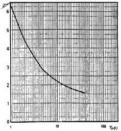
76 Oscilloscope clamp for AC current Model D38N (insulated AC current probe) DN series Curves at 50 Hz 30 A calibre Error on measurement Phase shift 300 A calibre Error on measurement Phase shift 3000 A calibre Error on measurement Phase shift Ed (2/5)


 DN series")


77 Oscilloscope clamp for AC current Model D38N (insulated AC current probe) DN series Frequency response 30 A calibre I = 10 A 300 A calibre I = 10 A 3000 A calibre I = 100 A Ed (3/5)

 DN series")
 30 A calibre")
 30")

78 Oscilloscope clamp for AC current Model D38N (insulated AC current probe) DN series Response to a step (I P = 1 A) 30 A calibre Response to a square signal (I P = 10 A) 30 A calibre 10 Hz 100 Hz 1 khz 10 khz Ed (4/5)
 Conditions of reference: 23 C ± 3 K, 20 % to 75 % RH, sinusoidal signal with frequency of 48 Hz at 65 Hz, external")
 Out of reference domain. To order AC current clamp model D38N for oscilloscope, with operating manual Reference P01120057A 906101970 - Ed 2-09 5.")
79 Oscilloscope clamp for AC current Model D38N (insulated AC current probe) DN series Influence of a DC current superimposed on the signal Maximum current according to the frequency (1) Conditions of reference: 23 C ± 3 K, 20 % to 75 % RH, sinusoidal signal with frequency of 48 Hz at 65 Hz, external magnetic field < 40 A/m, no DC components, no external conductor with circulating current, conductor centred for measurement, load impedance >1 MΩ / < 47 pf. (2) Out of reference domain. To order AC current clamp model D38N for oscilloscope, with operating manual Reference P A Ed (5/5)
80 Current clamps for AC current B100 series B series The only model in the B series, the B102 is designed to measure earth leakage currents caused by insulation faults. It enables the fault to be located and diagnosed before failure occurs thus avoiding installation shutdown. It is designed specifically for locating low-current faults on high-current circuits. The B102 measures differential or leakage current from 500 μa upwards and may be used to measure currents up to 400 A in continuous use (400 A max.). The B102 has two measurement ranges, 1 mv/ma or 1 mv/a. As a leakage current detector, the B102 can be used on single or multiphase systems whether the currents are in or out of phase, balanced or unbalanced. The B02 may be used simply as a high-precision clamp-on current probe. With its 115 mm jaw opening and dynamic measurement range from 500 μa to 400 A, the B102 is a versatile instrument, highly useful in the analysis of unbalanced circuits, leakage currents and earth loop currents. When operated in conjunction with an artificial neutral, the B102 can also be used to measure fault currents on 3-phase circuits with no neutral. (1) AN1 artificial neutral box (see capter 12) Ed (1/2)
81 Current clamps for AC current B100 series Ed (2/2)

82 mv Current clamp for AC current Model B102 (clamp for leakage currents) B100 series Current 4 A AC 400 A AC Output 1 mv / ma 1 mv / A Description The B102 clamp measures leakage currents or residual currents as low as 500 µa and can be used with multimeters equipped with a calibre in mv AC. The B102 clamp measures the currents flowing in earth loops as well as leakage currents. It can be used on live installations to detect insulation faults on the earth circuits of single and three-phase networks. For three-wire three-phase systems, use the artificial neutral box. Electrical specifications Current calibres: 0.5 ma AC...4 A AC 0.5 A AC A AC Output signal: 1 mv AC / ma AC (4 V for 4 A) 1 mv AC / A AC (0.4 V for 400 A) Accuracy and phase shift (1) : Calibre 4 A Primary current 0.5 ma 10 ma 10 ma 100 ma 100 ma 4 A Accuracy in % of output signal 3 % + 1 mv 0.5 % mv 0.5 % mv Phase shift not specified Calibre 400 A Primary current 0.5 ma 10 ma 10 A 200 A 200 A 400 A Accuracy in % of output signal 0.5 % mv 0.35 % mv 0.35 % mv Phase shift not specified Bandwidth: 30 khz...1 khz (depending on current value) Maximum currents: 400 A AC continuous for a frequency 1 khz: Peak current < 1000 A Max. voltage output: Electronic protection limiting the voltage to 6 Vpeak max. Influence of temperature: Measurement: 100 ppm/k or 0.1 % of output signal per 10 K Influence of adjacent conductor: 0.4 ma/a typical at 50 Hz Influence of an external field: n 4 A calibre: 60 ma n 400 A calibre: 0.1 A n for 400 A/m calibre at 50 Hz Influence of conductor position in jaws: 0.1 % of the reading at 50/60 Hz (nonresidual current) 0.2 % of the reading at 50/60 Hz (residual current) Influence of a DC current superimposed on the rated AC current: n 4 A calibre: 1 ma n 400 A calibre: 0.1 A for a current DC of 1 A Influence of frequency: n 4 A calibre: 2 % n 400 A calibre: 0.5 % from 30 Hz to 1 khz (limited to 100 A for 1 khz) Influence of the measurement instrument s input impedance: n 4 A calibre: E% = [Ze/(Ze + 4.8)-1]*100 n 400 A calibre: E% = [Ze/(Ze )-1]*100 Mechanical specifications Operating temperature: -10 C to +55 C Storage temperature: -40 C to +70 C Max. jaw insertion capacity: Cables: Ø 115 mm Bars: 1 busbar 20 x 50 mm Casing protection rating: IP 40 with clamp closed (NF EN Ed. 95) IP 30 with jaws open Relative humidity for operation: 0 to 85 % RH with a linear decrease above 35 C Operating altitude: 0 to 2,000 m Drop test: 1 m (NF EN ) Self-extinguishing capability: Casing: V0 according to UL94 Jaws: V2 according to UL94 Dimensions: 285 x 175 x 43 mm Weight: 1.3 kg approx. Colours: Casing: dark grey Jaws: red Output: Cable with double insulation, length 1.5 m, terminated by 2 insulated elbowed male Ø 4 mm banana plugs Safety specifications Electrical safety: Instrument with double insulation or reinforced insulation between the primary, the secondary and the grippable part located under the guard as per EN Ed. 2: 2001, EN Ed & EN Ed V category III, pollution degree V category IV, pollution degree 2 Electromagnetic compatibility: CE-certified equipment compliant with standard EN (Ed. 97) + A1 (Ed. 98) + A2 (Ed. 01) - Emission: regulations for class B equipment (domestic use) - Immunity: regulations for equipment operated intermittently on industrial sites Ed (1/2)
83 Current clamp for AC current Model B102 (clamp for leakage currents) B100 series Curves at 50 Hz 4 A calibre 400 A calibre Linearity for AC Linearity at 50 Hz: 1V/A calibre 4 % 3 % 2 % 1 % 0 % 0,1 ma 1 ma 10 ma 100 ma 1000 ma ma Current in ma Linearity at 50 Hz: 1mV/ 0,5 % 0,4 % 0,3 % 0,2 % 0,1 % 0,0 % -0,1 % 0,1 A 1 A 10 A 100 A 1000 A Current in A Phase shift Phase error at 50 Hz: ma 100 ma 1000 ma ma Current in ma Phase error at 50 Hz: 1mV/A calibre 0,06 0,05 0,04 0,03 0,02 0,01 0,00 10 A 100 A 1000 A Current in A Frequency response 4 A calibre 400 A calibre Typical error on measurement Frequency response at 2 A: 1V/A calibre Frequency response at 100 A: 1mV/A calib 20 % 20 % 10 % 10 % 0 % 0 % -10 % 10 Hz 100 Hz 1000 Hz Hz Hz Frequency in Hz -10 % 10 Hz 100 Hz 1000 Hz Hz Hz Frequency in Hz Phase shift typical Frequency response at 2 A: 1V/A calibre 10 Hz 100 Hz 1000 Hz Hz Hz Frequency in Hz Frequency response at 100 A Hz 100 Hz 1000 Hz Hz Hz Frequency in Hz (1) Conditions of reference: 23 C ± 3 K, 20 % to 75 % RH, sinusoidal signal with frequency of 48 to 65 Hz, distortion factor < 1 %, no DC components, external magnetic field < 40 A/m, no AC magnetic field, no external conductor with current flowing, conductor centred for measurement, load impedance 10 MΩ / 100 pf. To order AC current clamp model B102 with operating manual Accessories: AN1 artificial neutral box (see capter 12) Bag No. 11 Reference P P P Ed (2/2)

84 Flexible probes for AC current MiniFLEX series MiniFLEX series Making use of the principle of Rogowski coils, the MiniFLEX models are flexible sensors offering a wide dynamic range for measuring AC currents and viewing high-speed current pulses. The sensor s output voltage is proportional to the derivative of the current measured in the conductor and requires an electronic system for formatting. The absence of a magnetic core at the centre of the coil brings several advantages: - flexibility and light weight - excellent response to rapid current changes, as it is not possible for induced Fourier currents to occur, so they do not increase the sensor s response time. - excellent linearity due to the absence of core saturation even when there are very high current, as in the case of electric power transmission, electrical welding or applications involving high-power pulses. The great care taken when manufacturing our sensors means they benefit from particularly homogeneous winding, with equidistant turns along the whole length of the sensor, thus ensuring good immunity against electromagnetic interference. The MiniFLEX models are made up of a flexible sensor connected to a casing containing processing electronics which outputs a voltage with the same amplitude and form as the current measured. n MiniFLEX MA100 series: With their small diameter and size, the sensors in the MA100 series are ideal for measuring currents in the electrical cabinets of residential or tertiary buildings or in low-power cabinets in industry. Available with banana or BNC connection technology, the MA100 series can be connected directly to a multimeter, a wattmeter or a logger for RMS measurements at the standard industrial frequencies. n MiniFLEX MA200 series: The MA200 series is a family of high-frequency sensors specially designed for viewing and measuring electrical or electrotechnical signals with wide variations and high amplitude. These insulated current probes for oscilloscopes offer a bandwidth of 1 MHz and can be used to analyse currents with complex forms, transients present in electronic power supplies, welding units, etc Ed (1/2)
85 Flexible probes for AC current MiniFLEX series 5.5 mm 19 mm 124 mm 64 mm Ed (2/2)
 linked to a casing containing electronics.")
 while remaining easy to use. The sensors flexibility makes it simple to clamp and measure any conductor, whatever its type (cable, busbar, strand, etc.")
86 Flexible probe for AC current Model MA /3 MiniFLEX series Current 30 A AC 300 A AC Output 100 mv / A 10 mv / A Description The model MA100 MiniFLEX sensor is a flexible sensor comprising an active part (Rogowski coil) linked to a casing containing electronics. Unlike a current clamp with magnetic circuits, the MiniFLEX models are flexible and are not subject to magnetic saturation constraints, so they offer excellent linearity, low phase shift and a large dynamic range for measurement (up to several ka) while remaining easy to use. The sensors flexibility makes it simple to clamp and measure any conductor, whatever its type (cable, busbar, strand, etc. and accessibility). The click-lock system for opening and closing the coil is specially designed for use with safety gloves. Depending on the model, the MA100 can be connected to the AC voltage input of: - any multimeter with Ø 4 mm female plugs with 19 mm spacing - any measurement instrument equipped with BNC connection technology. Specifications for current measurement (1) Calibre 30 A 300 A Measurement range in use A AC A AC Specified measurement range (2) A AC A AC Output/input ratio 100 mv/a 10 mv/a Bandwidth at -3 db 2 Hz 20 khz Accuracy in % of output signal 1 % Phase shift at 50 Hz 1.5 Residual current (noise) at I = A rms Output impedance 1 kω Ed (1/4)
87 Flexible probe for AC current Model MA /3 MiniFLEX series Electrical specifications (1) Operating voltage: 600 V rms (Cat. IV) 1000 V rms (Cat. III) Battery: 9 V alkaline battery (NEDA 1604A, IEC 6LR61) Battery life: 100 hours typical Typical consumption: 3.6 ma typical Battery level indication: Green LED when > 7.0 V approx. Influence of battery voltage: 0.1 % from 9 V to 7 V Influence of temperature: 0.2 % / 10 K Influence of humidity: 0.3 % from 10 % to 90 % RH without condensation Influence of conductor position in the sensor (5) : 2.5 % Influence of sensor deformation (3) : 1.5 % Influence of an adjacent conductor with circulating AC current (4) : 1 % or 40 db Common mode rejection: - between enclosure and secondary: 65 db - between sensor and secondary: 88 db Influence of the measurement instrument s impedance Z: 0.1 % / Z (in MΩ) Mechanical specifications Clamping capacity: Model 170 mm: Ø max 45 mm Operating temperature: -10 C to +55 C Storage temperature: -40 C to +70 C Max. temperature of clamped conductor (measured): 90 C Relative humidity for operation: 0 to 85 % RH with a linear decrease above 35 C Operating altitude: 0 to 2,000 m Storage altitude: 12,000 m Casing protection rating (leakproofing): Casing: IP50 Sensor: IP50 according to EN 60529/A1 Ed. 06/2000 Shock resistance: IK04 according to EN Ed Self-extinguishing capability: Casing: UL94-V2 Sensor: UL94 V0 Dimensions: Casing: 140 x 64 x 28 mm Connector lead: 2 m (connects sensor to casing) Ø of sensor: 5.5 mm approx. Connection cable Ø: 3 mm approx. Colours: Sensor: red Sensor closing system: dark grey Sensor locking tab: yellow Casing: dark grey Output: Depending on model: - 2 x Ø 4 mm safety plugs with 19 mm spacing or - Coaxial cable 40 cm long, terminated by an insulated BNC plug Safety specifications Electrical safety: Class II equipment with double or reinforced insulation between the primary and the secondary (winding connected to the connection cable) as per EN and : V Cat. III, pollution degree V Cat. IV, pollution degree 2 - Type-B sensor V Cat. III between the terminals or between the BNC output (depending on model) and the external enclosure of the casing Electromagnetic compatibility (EMC): Complies with the IEC (Ed. 1997) + A1 (Ed. 1998) - Adequate immunity to disturbances for industrial environments - Adequate immunity to disturbances for residential environments (1) Conditions of reference: 23 C ± 5 K, 20 % to 75 % RH Battery voltage: 9 V ± 0.5 V Continuous external DC magnetic field (earth field) < 40 A/m Absence of external AC magnetic field External electrical field < 1 V/m Position of conductor measured: centred in the measurement coil Shape of measurement coil: quasi-circular Measurement instrument input impedance (oscilloscope) 1 MΩ Frequency and form of signal measured: 40 to 400 Hz sinusoidal. (2) Measurement range for the specifications indicated in this document (3) Any position, Ø of conductor measured 5 mm (4) Adjacent conductor 1 cm from sensor, 2 % or 34 db near click-lock system (5) 6 % near click-lock system To order MiniFLEX MA A / 3 V, length 170 mm, output via 2 x Ø 4 mm safety plugs with 19 mm spacing, with operating manual and battery Reference P MiniFLEX MA A / 3 V, length 170 mm, insulated BNC output with BNC Ø 4 mm banana adapter, with operating manual and battery P Ed (2/4)
 linked to a casing containing electronics.")
 while remaining easy to use. The sensors flexibility makes it simple to clamp and measure any conductor, whatever its type (cable, busbar, strand, etc.")
88 Flexible probe for AC current Model MA /3 MiniFLEX series Current 300 A AC 3000 A AC Output 10 mv / A 1 mv / A Description The MiniFLEX MA100 sensor is a flexible sensor comprising an active part (Rogowski coil) linked to a casing containing electronics. Unlike a current clamp with magnetic circuits, the MiniFLEX models are flexible and are not subject to magnetic saturation constraints, so they offer excellent linearity, low phase shift and a large dynamic range for measurement (up to several ka) while remaining easy to use. The sensors flexibility makes it simple to clamp and measure any conductor, whatever its type (cable, busbar, strand, etc. and accessibility. The click-lock system for opening and closing the coil is specially designed for use with safety gloves. Depending on the model, the MA100 can be connected to the AC voltage input of: - any multimeter with Ø 4 mm female plugs with 19 mm spacing - any measurement instrument equipped with BNC connection technology. Specifications for current measurement (1) Calibre 300 A 3000 A Measurement range in use A AC A AC Specified measurement range (2) A AC A AC Output/input ratio 10 mv/a 1 mv/a Bandwidth at -3 db (6) 2 Hz 20 khz Accuracy in % of output signal 1 % Phase shift at 50 Hz 1.5 Residual current (noise) at I = A rms Output impedance 1 kω Ed (3/4)
89 Flexible probe for AC current Model MA /3 MiniFLEX series Electrical specifications (1) Operating voltage: 600 V rms (Cat. IV) 1000 V rms (Cat. III) Battery: 9 V alkaline battery (NEDA 1604A, IEC 6LR61) Battery life: 100 hours typical Typical consumption: 3.6 ma typical Battery level indication: Green LED when > 7.0 V approx. Influence of battery voltage: 0.1 % from 9 V to 7 V Influence of temperature: 0.2 % / 10 K Influence of humidity: 0.3 % from 10 % to 90 % RH without condensation Influence of conductor position in the sensor (5) : 2.5 % Influence of sensor deformation (3): 1.5 % Influence of an adjacent conductor with circulating AC current (4) : 1 % or 40 db Common mode rejection: - between enclosure and secondary: 65 db - between sensor and secondary: 88 db Influence of the measurement instrument s impedance Z: 0.1 % / Z (in MΩ) Mechanical specifications Clamping capacity: Model 250 mm: Ø max 70 mm Model 350 mm: Ø max 100 mm Operating temperature: -10 C to +55 C Storage temperature: -40 C to +70 C Max. temperature of clamped conductor (measured): 90 C Relative humidity for operation: 0 to 85 % RH with a linear decrease above 35 C Operating altitude: 0 to 2,000 m Storage altitude: 12,000 m Casing protection rating (leakproofing): Casing: IP50 Sensor: IP50 according to EN 60529/A1 Ed. 06/2000 Shock resistance: IK04 according to EN Ed Self-extinguishing capability: Casing: UL94-V2 Sensor: UL94 V0 Dimensions: Casing: 140 x 64 x 28 mm Connector lead: 2 m (connects sensor to casing) Ø of sensor: 5.5 mm approx. Connection cable Ø: 3 mm approx. Colours: Sensor: red Sensor closing system: dark grey Sensor locking tab: yellow Casing: dark grey Output: Depending on model: - 2 x Ø 4 mm safety plugs with 19 mm spacing or - Coaxial cable 40 cm long, terminated by an insulated BNC plug Safety specifications Electrical safety: Class II equipment with double or reinforced insulation between the primary and the secondary (winding connected to the connection cable) as per EN and : V Cat. III, pollution degree V Cat. IV, pollution degree 2 - Type-B sensor V Cat. III between the terminals or between the BNC output (depending on model) and the external enclosure of the casing Electromagnetic compatibility (EMC): Complies with the IEC (Ed. 1997) + A1 (Ed. 1998) - Adequate immunity to disturbances for industrial environments - Adequate immunity to disturbances for residential environments (1) Conditions of reference: 23 C ± 5 K, 20 % to 75 % RH Battery voltage: 9 V ± 0.5 V Continuous external DC magnetic field (earth field) < 40 A/m Absence of external AC magnetic field External electrical field < 1 V/m Position of conductor measured: centred in the measurement coil Shape of measurement coil: quasi-circular Measurement instrument input impedance (oscilloscope) 1 MΩ Frequency and form of signal measured: 40 to 400 Hz sinusoidal. (2) Measurement range for the specifications indicated in this document (3) Any position, Ø of conductor measured 5 mm (4) Adjacent conductor 1 cm from sensor, 2 % or 34 db near click-lock system (5) 6 % near click-lock system (6) Frequency limitation according to amplitude Frequency limitation according to amplit Frequency in Hz To order Reference MiniFLEX MA100 MiniFLEX MA100 MiniFLEX MA100 MiniFLEX MA A / 3 V, length 250 mm, output via 2 x Ø 4 mm safety plugs with 19 mm spacing, with operating manual and battery A / 3 V, length 350 mm, output via 2 x Ø 4 mm safety plugs with 19 mm spacing, with operating manual and battery A / 3 V, length 250 mm, insulated BNC output with BNC Ø 4 mm banana adapter, with operating manual and battery A / 3 V, length 350 mm, insulated BNC output with BNC Ø 4 mm banana adapter, with operating manual and battery P P P P Ed (4/4)
 linked to a casing containing electronics.")
90 Flexible probe for AC current Model MA /3 (insulated AC current probe) MiniFLEX series Current 45 A peak 450 A peak Output 100 mv / A 10 mv / A Description The MiniFLEX MA200 is a flexible sensor comprising an active part (Rogowski coil) linked to a casing containing electronics. Unlike a current clamp with magnetic circuits, the MiniFLEX models are flexible and are not subject to magnetic saturation constraints, so they offer excellent linearity, low phase shift and a large dynamic range for measurement (up to several ka) while remaining easy to use. The oscilloscope probes in the MA200 series a specially designed for viewing alternating currents in order to assess the transition and propagation times on electrotechnical equipment. The sensors flexibility makes it simple to clamp and measure any conductor, whatever its type (cable, busbar, strand, etc. and accessibility. The click-lock system for opening and closing the coil is specially designed for use with safety gloves. The casing can be connected to any oscilloscope equipped with an AC voltage input. Specifications for current measurement (1) Calibre 30 A 300 A Measurement range in use Specified measurement range (2) A AC (45 A peak) A AC (45 A peak) A AC (450 A peak) A AC (450 A peak) Output/input ratio 100 mv/a 10 mv/a Accuracy in % of output signal 1 % A Phase shift at 1 khz 1.5 Residual current (noise) at I = 0 Output impedance 0.5 A rms 1 kω Frequency measurement specifications (1) Calibre 30 A 300 A Bandwidth at -3 db 2 Hz 1 MHz 2 Hz 1 MHz Rise time (3) (10 to 90 %) Fall time (4) (10 to 90 %) 0.3 µs (typical) 0.24 µs (typical) Propagation time (5) (to 10 %) 0.4 µs (typical) 0.3 µs (typical) Insertion impedance at 10 khz < 0.05 mω Ed (1/7)
91 Flexible probe for AC current Model MA /3 (insulated AC current probe) MiniFLEX series Electrical specifications (1) Operating voltage: 600 V rms (Cat. IV) 1000 V rms (Cat. III) Battery: 9 V alkaline battery (NEDA 1604A, IEC 6LR61) Battery life: 100 hours typical Typical consumption: 3.6 ma typical Battery level indication: Green LED when > 7.0 V approx. Influence of battery voltage: 0.1 % from 9 V to 7 V Influence of temperature: 0.2 % / 10 K Influence of humidity: 0.5 % from 10 % to 90 % RH without condensation Influence of conductor position in the sensor (8) : 2.5 % Influence of sensor deformation (6): 1 % Influence of an adjacent conductor with circulating AC current (7): 1.5 % or 36.5 db Common mode rejection: - between enclosure and secondary: 75 db - between sensor and secondary: 80 db Influence of the measurement instrument s impedance Z: 0.1 % / Z (in MΩ) Mechanical specifications Clamping capacity: Model 170 mm: Ø max 45 mm Model 250 mm: Ø max 70 mm Operating temperature: -10 C to +55 C Storage temperature: -40 C to +70 C Max. temperature of clamped conductor (measured): 90 C Relative humidity for operation: 0 to 85 % RH with a linear decrease above 35 C Operating altitude: 0 to 2,000 m Storage altitude: 12,000 m Casing protection rating (leakproofing): Casing: IP50 Sensor: IP50 according to EN 60529/A1 Ed.06/2000 Shock resistance: IK04 according to EN Ed Self-extinguishing capability: Casing: UL94-V2 Sensor: UL94 V0 Dimensions: Casing: 140 x 64 x 28 mm Connector lead: 2 m (connects sensor to casing) Ø of sensor: 5.5 mm approx. Connection cable Ø: 3 mm approx. Colours: Sensor: red Sensor closing system: dark grey Sensor locking tab: yellow Casing: dark grey Output: Depending on model: Coaxial cable 40 cm long, terminated by an insulated BNC plug Safety specifications Electrical safety: Class II equipment with double or reinforced insulation between the primary and the secondary (winding connected to the connection cable) as per EN and : V Cat. III, pollution degree V Cat. IV, pollution degree 2 - Type-B sensor V Cat. III between the BNC output and the external enclosure of the casing Electromagnetic compatibility (EMC): Complies with the IEC (Ed. 1997) + A1 (Ed. 1998) - Adequate immunity to disturbances for industrial environments - Adequate immunity to disturbances for residential environments (1) Conditions of reference: 23 C ± 5 K, 20 % to 75 % RH Battery voltage: 9 V ± 0.5 V Continuous external DC magnetic field (earth field) < 40 A/m Absence of external AC magnetic field External electrical field < 1 V/m Position of conductor measured: centred in the measurement coil Shape of measurement coil: quasi-circular Measurement instrument input impedance (oscilloscope) 1 MΩ Frequency and form of signal measured: 40 to 400 Hz sinusoidal. (2) Measurement range for the specifications indicated in this document (3) Rise time (t r ) (4) Fall time (t f ) (5) Delay time (t d ) (6) Oblong shape (7) Adjacent conductor 1 cm from sensor ; 3 % or 30.5 db near click-lock system (8) 6 % near click-lock system (9) Typical curve obtained by mathematical modelling To order Reference MiniFLEX MA A / 3 V, length 170 mm with operating manual and battery P MiniFLEX MA A / 3 V, length 250 mm with operating manual and battery P Ed (2/7)
 170 mm")
 MiniFLEX series Pulse response")
 Pulse response 906201076 -")
92 Flexible probe for AC current Model MA /3 (insulated AC current probe) 170 mm loop - 30 A calibre Frequency and phase responses (9) MiniFLEX series Pulse response 170 mm loop A calibre Frequency and phase responses (9) Pulse response Ed (3/7)
 250 mm loop - 30 A calibre Frequency and phase")
 Pulse response 906201076 -")
93 Flexible probe for AC current Model MA /3 (insulated AC current probe) 250 mm loop - 30 A calibre Frequency and phase responses (9) MiniFLEX series Pulse response 250 mm loop A calibre Frequency and phase responses (9) Pulse response Ed (4/7)
 linked to a casing containing electronics.")
94 Flexible probe for AC current Model MA /3 (insulated AC current probe) MiniFLEX series Current Output 4500 A peak 1 mv / A Description The MiniFLEX MA200 is a flexible sensor comprising an active part (Rogowski coil) linked to a casing containing electronics. Unlike a current clamp with magnetic circuits, the MiniFLEX models are flexible and are not subject to magnetic saturation constraints, so they offer excellent linearity, low phase shift and a large dynamic range for measurement (up to several ka) while remaining easy to use. The oscilloscope probes in the MA200 series a specially designed for viewing alternating currents in order to assess the transition and propagation times on electrotechnical equipment. The sensors flexibility makes it simple to clamp and measure any conductor, whatever its type (cable, busbar, strand, etc. and accessibility. The click-lock system for opening and closing the coil is specially designed for use with safety gloves. The casing can be connected to any oscilloscope equipped with an AC voltage input. Specifications for current measurement (1) Calibre A Measurement range in use A AC (4500 A peak) Specified measurement range (2) A AC (4500 A peak) Output/input ratio 1 mv/a Accuracy in % of output signal 1 % A Phase shift at 1 khz 1.5 Residual current (noise) at I = A rms Output impedance 1 kω Frequency measurement specifications (1) Calibre Bandwidth at -3 db (6) Rise time (3) (10 to 90 %) Fall time (4) (10 to 90 %) Propagation time (5) (to 10 %) Insertion impedance at 10 khz A 2 Hz 1 MHz 0.3 µs (typical) 0.4 µs (typical) < 0.05 mω Ed (5/7)
95 Flexible probe for AC current Model MA /3 (insulated AC current probe) MiniFLEX series Electrical specifications (1) Operating voltage: 600 V rms (Cat. IV) 1000 V rms (Cat. III) Battery: 9 V alkaline battery (NEDA 1604A, IEC 6LR61) Battery life: 100 hours typical Typical consumption: 3.6 ma typical Battery level indication: Green LED when > 7.0 V approx. Influence of battery voltage: 0.1 % from 9 V to 7 V Influence of temperature: 0.6 % / 10 K Influence of humidity: 0.5 % from 10 % to 90 % RH without condensation Influence of conductor position in the sensor (9) : 2.5 % Influence of sensor deformation (7): 1 % Influence of an adjacent conductor with circulating AC current (8) : 1.5 % or 36.5 db Common mode rejection: - between enclosure and secondary: 75 db - between sensor and secondary: 80 db Influence of the measurement instrument s impedance Z: 0.1 % / Z (in MΩ) Mechanical specifications Clamping capacity: Model 350 mm: Ø max 100 mm Operating temperature: -10 C to +55 C Storage temperature: -40 C to +70 C Max. temperature of clamped conductor (measured): 90 C Relative humidity for operation: 0 to 85 % RH with a linear decrease above 35 C Operating altitude: 0 to 2,000 m Storage altitude: 12,000 m Casing protection rating (leakproofing): Casing: IP50 Sensor: IP50 according to EN 60529/A1 Ed. 06/2000 Shock resistance: IK04 according to EN Ed Self-extinguishing capability: Casing: UL94 V2 Sensor: UL94 V0 Dimensions: Casing: 140 x 64 x 28 mm Connector lead: 2 m (connects sensor to casing) Ø of sensor: 5.5 mm approx. Connection cable Ø: 3 mm approx. Colours: Sensor: red Sensor closing system: dark grey Sensor locking tab: yellow Casing: dark grey Output: Coaxial cable 40 cm long, terminated by an insulated BNC plug Safety specifications Electrical safety: Class II equipment with double or reinforced insulation between the primary and the secondary (winding connected to the connection cable) as per EN and : V Cat. III, pollution degree V Cat. IV, pollution degree 2 - Type-B sensor V Cat. III between the BNC output and the external enclosure of the casing Electromagnetic compatibility (EMC): Complies with the IEC (Ed. 1997) + A1 (Ed. 1998) - Adequate immunity to disturbances for industrial environments - Adequate immunity to disturbances for residential environments (1) Conditions of reference: 23 C ± 5 K, 20 % to 75 % RH Battery voltage: 9 V ± 0.5 V Continuous external DC magnetic field (earth field) < 40 A/m Absence of external AC magnetic field External electrical field < 1 V/m Position of conductor measured: centred in the measurement coil Shape of measurement coil: quasi-circular Measurement instrument input impedance (oscilloscope) 1 MΩ Frequency and form of signal measured: 40 to 400 Hz sinusoidal. (2) Measurement range for the specifications indicated in this document (3) Rise time (tr) (4) Fall time (tf) (5) Delay time (td) (6) Frequency limitation according to amplitude Frequency limitation up to 3,000 A 3500 A 3000 A 2500 A 2000 A 1500 A 1000 A 500 A 0 A 1000 Hz Hz Hz Frequency (Hz) (7) Oblong shape (8) Adjacent conductor 1 cm from sensor ; 3 % or 30.5 db near click-lock system (9) 6 % near click-lock system (10) Typical curve obtained by mathematical modelling To order Reference MiniFLEX MA A / 3 V, length 350 mm with operating manual and battery P Ed (6/7)
96 Flexible probe for AC current Model MA /3 (insulated AC current probe) MiniFLEX series 3000 A calibre Frequency and phase responses (10) Pulse response Ed (7/7)
 to manufacturers of measurement, location and detection instruments.")

97 Flexible probe for AC current Model MA101 MiniFLEX series CAUTION These products are only offered under certain conditions (quantity, etc.) to manufacturers of measurement, location and detection instruments. MiniFLEX sensors offer excellent linearity, low phase shift and a large measurement range (up to several ka), as well as unrivalled simplicity of use. The MA101 series is Chauvin Arnoux s response to all the measurement instrument manufacturers seeking to integrate the MiniFLEX solution as native in their measurement products, particularly for industrial or tertiary applications involving difficult access or confined spaces. Models produced on request Sensor length From 140 mm Connection cable length From 50 cm Connection Tinned bare wires, BNC, FRB, Pairing Multi-sensor use,. Description The MA 101 MiniFLEX sensor is a flexible sensor comprising an active part (Rogowski coil) and a connection cable. It requires additional electronics (not delivered with the sensor). For applications where several sensors need to be used (three-phase measurements, etc.), Chauvin Arnoux carries out an additional operation during manufacturing to ensure that they are fully interchangeable. Electrical specifications (1) Voltage developed at sensor terminals: 46.5 µv / A (-15 % / +10 %) at 50 Hz Linearity (1) : 0.3 % Phase shift (1): -90 ± 0,5 at 50 Hz Bandwidth: Depends on associated electronics Interchangeability error: 0.5 % (maximum error between 2 paired sensors on the same measurement point) Operating voltage: 600 V rms or DC (Cat. IV) 1000 V rms or DC (Cat. III) Influence of temperature: 0.05 %/10 k from -20 C to +60 C Influence of humidity: 0.1 % from 10 % to 90 % RH Influence of conductor position with no sensor deformation: 1.5 % Influence of adjacent conductor placed 1 cm from sensor: 0.7 % of the adjacent current at 50 Hz Influence of sensor deformation (flattened/oblong shape): 0.5 % Common mode rejection (2) : 100 db for a voltage of 600 V/50 Hz applied between the sensor enclosure and the secondary Mechanical specifications Clamping capacity: Depends on sensor length Operating temperature: -20 C to +60 C Storage temperature: -40 C to +80 C Max. temperature of clamped conductor (measured): 90 C Operating altitude: 0 to 2,000 m Storage altitude: 12,000 m Casing protection rating (leakproofing): IP50 according to EN 60529/A1 Ed.06/2000 Self-extinguishing capability: UL94 V0 Dimensions: Ø of sensor: 5.5 mm approx. Connection cable Ø: 3 mm approx. Weight: 30 g approx. per 10 cm length of sensor Colours: Sensor: red Sensor closing system: dark grey Sensor locking tab: yellow Connection cable: Length as requested, with 10 cm increments Connection: As requested: specify reference, model and pin configuration required Safety specifications Electrical safety: Class II equipment with double or reinforced insulation between the primary and the secondary (winding connected to the connection cable) as per EN and : V Cat. III, pollution degree V Cat. IV, pollution degree 2 - Type-B sensor Electromagnetic compatibility (EMC): Not applicable as delivered. Applicable only for the sensor with its associated electronics which must include EMC protection systems. The sensor does not contain any EMC protection systems (as it is by nature an electromagnetic field sensor). (1) Conditions of reference: 23 C ± 5 K, 20 to 75 % RH, continuous external magnetic field < 40 A/m, absence of magnetic and electrical fields, frequency of signal measured 10 Hz to 100 Hz sinusoidal (2) Ratio expressed in db to be converted into the equivalent in Amperes while taking into account the sensor s sensitivity and the gain of the associated electronics. To receive a quotation, please answer the following questions: What sensor length do you require? (140 mm minimum, with 10 mm increments) What connection cable length do you require? (50 cm minimum, with 10 cm increments) What connection system do you require? (the output from the sensor comprises 2 active conductors (hot point, cold point) and shielding) Does your application use several MA 101 sensors? If YES, is sensor interchangeability required? If YES, what is the input impedance of the equipment to which the MA 101 will be connected?. mm. cm None (tinned bare wires) or Specify connector reference, model and manufacturer and the wiring required YES / NO YES / NO. Ω Ed (1/1)

98 Flexible probes for AC current AmpFLEX TM series AmpFLEX series These flexible current probes are as at home measuring low AC currents of a few hundred ma as they are measuring high currents of several tens of ka. Their main point of interest is their flexibility and the ease with which electrical conductors of all shapes and sizes (cables, busbars) and degrees of accessibility can be gripped. They have a number of other advantages; they are lightweight (no magnetic circuit), they do not suffer from the saturation effect and their high level of accuracy combined with minimal phase shift make them perfect for power measurement applications. n AmpFLEX A100 series: The A100 (pictured above) has a flexible toroid which connects, via a screened lead, to a small unit containing all the processing electronics and a standard 9 V battery. The unit can be connected directly to any multimeter, wattmeter or recording device. With either one or two calibres, the A100 models give an AC voltage output of or 100 mv/a. As well as the standard models (45, 80, or 120 cm s), there are also models available on request for which you can choose the sensor length and sensitivity. n AmpFLEX A101 series: The A101 has exactly the same specification as the A100 models but comes without the electronic unit. These sensors are used by other manufacturers and integrated into their own test and measurement products Ed (1/2)
99 Flexible probes for AC current AmpFLEX TM series Ø 12 mm L = 200 mm 64 mm A 100 AC CURRENT PROBE 118 mm Ed (2/2)
100 Flexible probe for AC current Model A / 2 AmpFLEX TM series Current 20 A AC 200 A AC Output 100 mv / A 10 mv / A Electrical specifications Current calibres: 0.5 A AC 20 A AC 0.5 A AC 200 A AC Output signal: 100 mv AC / A AC (2 V for 20 A) 10 mv AC / A AC (2 V for 200 A) Accuracy (1): A 100 AC CURRENT PROBE Calibre 20 A 200 A Primary current 0.5 A 5 A 5 20 A 0.5 A 5 A 0.5 A 200 A % Accuracy of output signal not specified 1 % not specified 1 % Phase shift Bandwidth: 10 Hz 20 khz Crest factor: 2.25 at rated current Max. current / Max. output voltage: No current limit, but maximum output is 4.5 V peak Load impedance: 1 MΩ Influence of Z load impedance: 0.1 % / Z, (Z in MΩ) Output impedance: 1 kω DC voltage shift at output: n 20 A calibre: 50 mv DC n 200 A calibre: 5 mv DC Operating voltage: 1000 V rms Influence of adjacent conductor: 1 % interference current at 50 Hz ( 2 % near click-lock system) Influence of conductor position in loop: 1 % ( 4 % near click-lock system) Influence of sensor shape: 1 % for an oblong shape Battery: 9 V alkaline battery (NEDA 1604A, IEC 6LR61) Battery life: 150 hrs continuous, 1000 x 1 minute measurements Low battery signal: Green LED: battery OK Flashing green LED: low battery No green LED: battery discharged Overload signal: red LED Mechanical specifications Operating temperature: -10 C to +55 C, (maximum temperature for sensor is 90 C) Storage temperature: -40 C to +70 C Influence of temperature: 0.5 % of output signal per 10 K Relative humidity for operation: 0 to 95 % RH with a linear decrease above 35 C Influence of relative humidity: < 0.2 % of output signal from 10 % to 85 % RH Operating altitude: 0 to 2,000 m Casing protection rating: Casing: IP40 (IEC 529) Flexible sensor: IP65 (IEC 529) Drop test: 1 m (IEC ) Shock resistance: 100 g (IEC ) Vibration resistance (IEC ): 5/15/5 1.5 mm 15/25/15 1 mm 25/55/ mm Self-extinguishing capability: Casing, flexible sensor and click-lock system: UL94 V0 Dimensions: Casing: 140 x 64 x 28 mm (overall) Connector lead: 2 m (connects sensor to casing) Flexible sensor: Ø 12 mm ± 0.5 mm Weight: Casing: < 200 g Flexible sensor: approx. 30 g per 10 cm length Bending radius: 15 mm Colours: Casing and connection leads: dark grey, red flexible sensor with dark grey click-lock system Output: 2 safety sockets (4 mm) spacing 19 mm Safety specifications Electrical safety: Double insulation or reinforced insulation between primary, secondary and outer parts of casing liable to be handled, IEC V category III, pollution degree 2 Electromagnetic compatibility (EMC): EN : compliant EN : - Electrostatic discharge: IEC Radiated field: IEC Fast transients: IEC Electrical shocks: IEC Magnetic field at 50/60 Hz: IEC (1) Conditions of reference: 23 C ± 5 K, 20 % to 75 % RH, battery voltage: 9 V ± 0.5 V, external DC magnetic field < 40 A/m, no external magnetic or electrical field, conductor centred for measurement, sinusoidal signal: Hz. To order AmpFLEX / 2, length 45 cm with operating manual Reference P Ed (1/1)
101 Flexible probe for AC current Model A / 2 AmpFLEX TM series Current Output 2000 A AC 1 mv / A Electrical specifications Current calibre: 0.5 A AC 2000 A AC Output signal: 1 mv AC / A AC (2 V for 2000 A) Accuracy (1) : A 100 AC CURRENT PROBE Primary current 0.5 A 5 A 5 A 2000 A % Accuracy of output signal not specified 1 % Phase shift Bandwidth: 10 Hz 20 khz Crest factor: 2.25 at rated current Max. current / Max. output voltage: No current limit, but maximum output is 4.5 V peak Load impedance: 1 MΩ Influence of Z load impedance: 0.1 % / Z, (Z in MΩ) Output impedance: 1 kω DC voltage shift at output: 2 mv DC Operating voltage: 1000 V rms Influence of adjacent conductor: 1 % interference current at 50 Hz ( 2 % near click-lock system) Influence of conductor position in loop: 1 % ( 4 % near click-lock system) Influence of sensor shape: 1 % for an oblong shape Battery: 9 V alkaline battery (NEDA 1604A, IEC 6LR61) Battery life: 150 hrs continuous, 1000 x 1 minute measurements Low battery signal: Green LED: battery OK Flashing green LED: low battery No green LED: battery discharged Overload signal: red LED Mechanical specifications Operating temperature: -10 C to +55 C, (maximum temperature for sensor is 90 C) Storage temperature: -40 C to +70 C Influence of temperature: 0.5 % of output signal per 10 K Relative humidity for operation: 0 to 95 % RH with a linear decrease above 35 C Influence of relative humidity: < 0.2 % of output signal from 10 % to 85 % RH Operating altitude: 0 to 2,000 m Casing protection rating: Casing: IP40 (IEC 529) Flexible sensor: IP65 (IEC 529) Drop test: 1 m (IEC ) Shock resistance: 100 g (IEC ) Vibration resistance (IEC ): 5/15/5 1.5 mm 15/25/15 1 mm 25/55/ mm Self-extinguishing capability: Casing, flexible sensor and click-lock system: UL94 V0 Dimensions: Casing: 140 x 64 x 28 mm (overall) Connector lead: 2 m (connects sensor to casing) Flexible sensor: Ø 12 mm ± 0.5 mm Weight: Casing: < 200 g Flexible sensor: approx. 30 g per 10 cm length Bending radius: 15 mm Colours: Casing and connection leads: dark grey, red flexible sensor with dark grey click-lock system Output: 2 safety sockets (4 mm) spacing 19 mm Safety specifications Electrical safety: Double insulation or reinforced insulation between primary, secondary and outer parts of casing liable to be handled, IEC V category III, pollution degree 2 Electromagnetic compatibility (EMC): EN : compliant EN : - Electrostatic discharge: IEC Radiated field: IEC Fast transients: IEC Electrical shocks: IEC Magnetic field at 50/60 Hz: IEC (1) Conditions of reference: 23 C ± 5 K, 20 to 75 % RH, battery voltage: 9 V ± 0.5 V, external DC magnetic field < 40 A/m, no external magnetic or electrical field, conductor centred for measurement, sinusoidal signal: Hz. To order AmpFLEX 2000 / 2, length 45 cm with operating manual AmpFLEX 2000 / 2, length 80 cm with operating manual Reference P P Ed (1/1)
102 Flexible probe for AC current Model A / 2 AmpFLEX TM series Current 200 A AC 2000 A AC Output 10 mv / A 1 mv / A Electrical specifications Current calibres: 0.5 A AC 200 A AC 0.5 A AC 2000 A AC Output signal: 10 mv AC / A AC (2 V for 200 A) 1 mv AC / A AC (2 V for 2000 A) Accuracy (1): A 100 AC CURRENT PROBE Calibre 200 A 2000 A Primary current 0.5 A 5 A 5 A 200 A 0.5 A 5 A 0.5 A 2000 A % Accuracy of output signal not specified 1 % not specified 1 % Phase shift Bandwidth: 10 Hz 20 khz Crest factor: 2.25 at rated current Max. current / Max. output voltage: No current limit, but maximum output is 4.5 V peak Load impedance: 1 MΩ Influence of Z load impedance: 0.1 % / Z, (Z in MΩ) Output impedance: 1 kω DC voltage shift at output: n 200 A calibre: 5 mv DC n 2000 A calibre: 2 mv DC Operating voltage: 1000 V rms Influence of adjacent conductor: 1 % interference current at 50 Hz ( 2 % near click-lock system) Influence of conductor position in loop: 1 % ( 4 % near click-lock system) Influence of sensor shape: 1 % for an oblong shape Battery: 9 V alkaline battery (NEDA 1604A, IEC 6LR61) Battery life: 150 hrs continuous, 1000 x 1 minute measurements Low battery signal: Green LED: battery OK Flashing green LED: low battery No green LED: battery discharged Overload signal: Red LED Mechanical specifications Operating temperature: -10 C to +55 C, (maximum temperature for sensor is 90 C) Storage temperature: -40 C to +70 C Influence of temperature: 0.5 % of output signal per 10 K Relative humidity for operation: 0 to 95 % RH with a linear decrease above 35 C Influence of relative humidity: < 0.2 % of output signal from 10 % to 85 % RH Operating altitude: 0 to 2,000 m Casing protection rating: Casing: IP40 (IEC 529) Flexible sensor: IP65 (IEC 529) Drop test: 1 m (IEC ) Shock resistance: 100 g (IEC ) Vibration resistance (IEC ): 5/15/5 1.5 mm 15/25/15 1 mm 25/55/ mm Self-extinguishing capability: Casing, flexible sensor and click-lock system: UL94 V0 Dimensions: Casing: 140 x 64 x 28 mm (overall) Connector lead: 2 m (connects sensor to casing) Flexible sensor: Ø 12 mm ± 0.5 mm Weight: Casing: < 200 g Flexible sensor: approx. 30 g per 10 cm length Bending radius: 15 mm Colours: Casing and connection leads: dark grey, red flexible sensor with dark grey click-lock system Output: 2 safety sockets (4 mm) spacing 19 mm Safety specifications Electrical safety: Double insulation or reinforced insulation between primary, secondary and outer parts of casing liable to be handled, IEC V category III, pollution degree 2 Electromagnetic compatibility (EMC): EN : compliant EN : - Electrostatic discharge: IEC Radiated field: IEC Fast transients: IEC Electrical shocks: IEC Magnetic field at 50/60 Hz: IEC (1) Conditions of reference: 23 C ± 5 K, 20 % to 75 % RH, battery voltage: 9 V ± 0.5 V, external DC magnetic field < 40 A/m, no external magnetic or electrical field, conductor centred for measurement, sinusoidal signal: Hz. To order AmpFLEX / 2, length 45 cm with operating manual AmpFLEX / 2, length 80 cm with operating manual Reference P P Ed (1/1)
103 Flexible probe for AC current Model A / 3 AmpFLEX TM series Current 300 A AC 3000 A AC Output 10 mv / A 1 mv / A Electrical specifications Current calibres: 0.5 A AC 300 A AC 0.5 A AC 3000 A AC Output signal: 10 mv AC / A AC (3 V for 300 A) 1 mv AC / A AC (3 V for 3000 A) Accuracy (1) : A 100 AC CURRENT PROBE Calibre 300 A 3000 A Primary current 0.5 A 5 A 5 A 300 A 0.5 A 5 A 0.5 A 3000 A % Accuracy of output signal not specified 1 % not specified 1 % Phase shift Bandwidth: 10 Hz 20 khz Crest factor: 1.5 at rated current Max. current / Max. output voltage: No current limit, but maximum output is 4.5 V peak Load impedance: 1 MΩ Influence of Z load impedance: 0.1 % / Z, (Z in MΩ) Output impedance: 1 kω DC voltage shift at output: n 300 A calibre: 5 mv DC n 3000 A calibre: 2 mv DC Operating voltage: 1000 V rms Common mode voltage: 600 V category III and pollution degree 2 Influence of adjacent conductor: 1 % interference current at 50 Hz ( 2 % near click-lock system) Influence of conductor position in loop: 1 % ( 4 % near click-lock system) Influence of sensor shape: 1 % for an oblong shape Battery: 9 V alkaline battery (NEDA 1604A, IEC 6LR61) Battery life: 150 hrs continuous, 1000 x 1 minute measurements Low battery signal: Green LED: battery OK Flashing green LED: low battery No green LED: battery discharged Overload signal: Red LED Mechanical specifications Operating temperature: -10 C to +55 C, (maximum temperature for sensor is 90 C) Storage temperature: -40 C to +70 C Influence of temperature: 0.5 % of output signal per 10 K Relative humidity for operation: 0 to 95 % RH with a linear decrease above 35 C Influence of relative humidity: < 0.2 % of output signal from 10 % to 85 % RH Operating altitude: 0 to 2,000 m Casing protection rating: Casing: IP40 (IEC 529) Flexible sensor: IP65 (IEC 529) Drop test: 1 m (IEC ) Shock resistance: 100 g (IEC ) Vibration resistance: 5/15/5 1.5 mm 15/25/15 1 mm 25/55/ mm (IEC ) Self-extinguishing capability: Casing, flexible sensor and click-lock system: UL94 V0 Dimensions: Casing: 140 x 64 x 28 mm (overall) Connector lead: 2 m (connects sensor to casing) Flexible sensor: Ø 12 mm ±0,5 mm Weight: Casing: < 200 g Flexible sensor: 30 g per 10 cm length Bending radius: 15 mm Colours: Case and connection leads: dark grey, red flexible sensor with dark grey click-lock system Output: 2 safety sockets (4 mm) spacing 19 mm Safety specifications Electrical safety: Double insulation or reinforced insulation between primary, secondary and outer parts of casing liable to be handled, IEC V category III, pollution degree 2 Electromagnetic compatibility (EMC): EN : compliant EN : - Electrostatic discharge: IEC Radiated field: IEC Fast transients: IEC Electrical shocks: IEC Magnetic field at 50/60 Hz: IEC (1) Conditions of reference: 23 C ± 5 K, 20 % to 75 % RH, battery voltage: 9 V ± 0.5 V, external DC magnetic field < 40 A/m, no external magnetic or electrical field, conductor centred for measurement, sinusoidal signal: Hz. To order AmpFLEX / 3, length 45 cm with operating manual AmpFLEX / 3, length 80 cm with operating manual AmpFLEX / 3, length 120 cm with operating manual Reference P P P Ed (1/1)
104 Flexible probe for AC current Model A / 1 AmpFLEX TM series Current 1000 A AC A AC Output 1 mv / A 0.1 mv / A Electrical specifications AC CURRENT PROBE Current calibres: A A AC 1000 A AC 0.5 A AC A AC Output signal: 1 mv AC / A AC (1 V for 1000 A) 0.1 mv AC / A AC (1 V for A) Accuracy (1) : Calibre 1000 A A Primary current 0.5 A 5 A 5 A 1000 A 0.5 A 50 A 0.5 A A % Accuracy of output signal not specified 1 % not specified 1 % Phase shift Bandwidth: 10 Hz [45 65] 20 khz Crest factor: 4.5 at rated current Max. current / Max. output voltage: No current limit, but maximum output is 4.5 V peak. Load impedance: 1 MΩ Influence of Z load impedance: 0.1 % / Z, (Z in MΩ) Output impedance: 1 kω DC voltage shift at output: n 1000 A calibre: 2 mv DC n A calibre: 1 mv DC Operating voltage: 1000 V rms Influence of adjacent conductor: 1 % interference current at 50 Hz ( 2 % near click-lock system) Influence of conductor position in loop: 1 % ( 4 % near click-lock system) Influence of sensor shape: 1 % for an oblong shape Battery: 9 V alkaline battery (NEDA 1604A, IEC 6LR61) Battery life: 150 hrs continuous, 1000 x 1 minute measurements Low battery signal: Green LED: battery OK Flashing green LED: low battery No green LED: battery discharged Overload signal: Red LED Mechanical specifications Operating temperature: -10 C to +55 C, (maximum temperature for sensor is 90 C) Storage temperature: -40 C to +70 C Influence of temperature: 0.5 % of output signal per 10 K Relative humidity for operation: 0 to 95 % RH with a linear decrease above 35 C Influence of relative humidity: < 0.2 % of output signal from 10 % to 85 % RH Operating altitude: 0 to 2,000 m Casing protection rating: Casing: IP40 (IEC 529) Flexible sensor: IP65 (IEC 529) Drop test: 1 m (IEC ) Shock resistance: 100 g (IEC ) Vibration resistance: 5/15/5 1.5 mm 15/25/15 1 mm 25/55/ mm (IEC ) Self-extinguishing capability: Casing, flexible sensor and click-lock system: UL94 V0 Dimensions: Casing: 140 x 64 x 28 mm (overall) Connector lead: 2 m (connects sensor to casing) Flexible sensor: Ø 12 mm ± 0.5 mm Weight: - Casing: < 200 g - Flexible sensor: approx. 30 g per 10 cm length Bending radius: 15 mm Colours: Casing and connection leads: dark grey, red flexible sensor with dark grey click-lock system Output: 2 safety sockets (4 mm) spacing 19 mm Safety specifications Electrical safety: Double insulation or reinforced insulation between primary, secondary and outer parts of casing liable to be handled, IEC V category III, pollution degree 2 Electromagnetic compatibility (EMC): EN : compliant EN : - Electrostatic discharge: IEC Radiated field: IEC Fast transients: IEC Electrical shocks: IEC Magnetic field at 50/60 Hz: IEC (1) Conditions of reference: 23 C ± 5 K, 20 % to 75 % RH, battery voltage: 9 V ± 0.5 V, external DC magnetic field < 40 A/m, no external magnetic or electrical field, conductor centred for measurement, sinusoidal signal: Hz. To order AmpFLEX / 1, length 120 cm with operating manual Reference P Ed (1/1)
105 Flexible probe for AC current Model A100 on request AmpFLEX TM series A 100 AC CURRENT PROBE To complete the comprehensive range of standard models presented on the preceding pages, Chauvin Arnoux also offers to make special models to meet your particular needs. In this way it is possible to define AmpFLEX flexible current sensors with sensitivities and lengths corresponding to your applications. To do so, it is necessary to give a reference as follows: A A B B B C C C D D D with: A : Number of ranges BBB : Max. range value, in Amperes CCC : Max. range sensitivity in mv/a DDD : Length of flexible sensor in cm (min X 40 = 40 cm, max = 990 cm) for a section of 10 cm Currently available values: Model A A B B B C C C D D D A / 2 V A X A / 2 V A K 0 X X A / 2 V A K 0 X X A / 3 V A K 0 X X A / 1 V A K 0. 1 Example 1: An AmpFLEX A100 flexible sensor, with 2 ranges A and length 5 m would be represented by: A K 0 X X ranges Max. range 2000 ( second range is 10 times smaller) Sensitivity 1 mv/a (sensitivity of second range is 10 times greater) Length of sensor in cm = 500 Example 2: An AmpFLEX flexible sensor, range 2000 A, length 90 cm would be represented by: A K 0 X X 1 x range Max. range 2000 Sensitivity 1 mv / A Length of sensor in cm = x 90 As Chauvin Arnoux is always seeking to improve its products, do not hesitate to contact us for other configurations Ed (1/1)
106 Flexible probe for AC current Model A101 AmpFLEX TM series CAUTION These products are only offered under certain conditions (quantity, etc.) to manufacturers of measurement, location and detection instruments. The AmpFLEX offers perfect linearity, low phase shift, a wide range of measurements (up to several ka) and unrivalled ease of use. The A101 series is Chauvin Arnoux s response to all the measurement instrument manufacturers wishing to integrate AmpFLEX solutions into their product lines. Description The A101 AmpFLEX sensor is composed of an active element (Rogowski coil) and a connection lead. It is necessary to add on an electronic processing system (not included), in order to complete this measurement device. Chauvin Arnoux has added an extra step to the manufacturing process of the A101 probe which guarantees their interchangeability. This is essential in applications such as three-phase measurements where several identical probes are used. Electrical specifications Voltage at sensor terminals: 46 µv / A (-15 % +10 %) at 50 Hz Linearity * : < 0.3 % Phase shift *: 0.5 at 50 Hz Interchangeability error: 0.5 % (maximum error between 2 sensors for the same measurement point). Frequency range: Depends on the electronics with which it is used. Operating voltage: 1000 V rms or DC Mechanical specifications Operating temperature: -20 C to +60 C Storage temperature: -0 C to + 80 C Max temperature of measured cable: 90 C Operating altitude: 0 to 2,000 m Maximum conductor size: Depending on sensor length. Casing protection rating: IP65 in accordance with EN Self-extinguishing capability: External cover, click-lock system, connection lead: UL94 V0 Dimensions: Ø of sensor: 12 mm Weight: Approx. 30 g per 10 cm length Colour: Sensor: red Click-lock system: dark grey Output: According to configuration (refer to Connections) Connexions: According to configuration (refer to Connections) Safety specifications Electrical safety: Double insulation or reinforced insulation between primary, secondary and outer parts of casing liable to be handled, IEC & IEC , 1000 V category III, pollution degree 2 Electromagnetic compatibility (EMC): EN : class B EN : - Electrostatic discharge: IEC Radiated field: IEC Fast transients: IEC Magnetic field at 50/60 Hz: IEC * Conditions of reference: 23 C ± 6 K, 20 % to 75 % RH, frequency 10 Hz to 100 Hz, sinusoidal signal, no external AC magnetic field, external magnetic field 40 A/m (earth field), conductor centred for measurement Ed (1/4)
107 Flexible probe for AC current Model A101 AmpFLEX TM series Configurations Level 1 A Category (fixed field) Lead length in decimetres Min value: 05 (50 cm) Max value: 99 (9.9 m) Increment per 1 dm section (10 cm) Length of connection lead in decimetres Min value: 05 (50 cm) Max value: 99 (9.9 m) Increment per section of 1 dm (10 cm) Measurement range (refer to additional information) 0: without 2: electronic diagram CA2 1: electronic diagram CA1 3: electronic diagram CA3 or C.A 833X and C.A 823X 4: diagram suited for C.A 8310 Connections X: lead without connection unit C: specific lead Calibration for interchangeability (refer to additional information) N: without O: with Special feature X1: plain sensor without CHAUVIN ARNOUX logo, with standard and AmpFLEX TM inscriptions, plain packing with instruction manual X2: plain sensor without CHAUVIN ARNOUX logo, with standard and AmpFLEX TM inscriptions, plastic bag packing, instruction manual stapled on the plastic bag C1: same as CHAUVIN ARNOUX sensor plain packing box with instruction manual C2: same as CHAUVIN ARNOUX sensor plastic bag packing, instruction manual stapled on the plastic bag Connections (refer to additional information) XXX1: circular lead 2 conductors + bare and tinned BNC1: coaxial lead + insulated coaxial plug FRB1: circular lead 2 conductors + screening with FRB connector D01 model, type 1 (male pins) FRB2: circular lead 2 conductors + screening with FRB connector D01 model, type 2 (sockets) 833X: specific connections for Qualistar C.A 833X and C.A 823X Colour of connector (refer to additional information) XX : no connector BK: black GN: green WH: white RD: red YE: yellow BU: blue + connection point 1, 2 or 3: contact N connected to + X: no connector -: for 833X and 823X connection: not concerned - connection point 1, 2 or 3: contact N connected to - X: no connector -: for 833X and 823X connection: not concerned Connected protection 1, 2 or 3: contact N connected to screening X: not connected or no connector -: for 833X and 823X connection: not concerned Level 2 Interchangeability resistors (refer to additional information) I: included in sensor F: resistors supplied D: values are indicated in the manual included with AmpFLEX (resistors not supplied) X: no calibration for interchangeability Ed (2/4)
108 Flexible probe for AC current Model A101 AmpFLEX TM series Specific configuration of sensors for C.A 8310 Power & Harmonics Analyser To complete the range of standard sensors for this product, A190 sensors of different lengths can be used (the A190 is simply a specific type of A101). Select: Level 1 A C O C 1 Level 2 F R B X I Blank spaces refer to: - level 1: sensor lengths and connection lead to be chosen - level 2: colour of connector Additional information Measurement range (electronic diagram) Choosing the measurement range depends on the sensitivity required and on electronic supply voltages. Example: For a supply voltage of ± 5 V, electronic output voltage will be limited to ± 4.5 V peak to peak, that is to say approximately 3 V RMS (4.5 V / 2) if measured signal is sinusoidal. The different diagrams refer to sensitivity ranges in accordance with the following chart: Diagram CA1 CA2 CA3 Sensitivity 0.1 mv / A 1 mv / A 1 mv / A 10 mv / A 10 mv / A 100 mv / A Max. measurement range for a ± 5 V supply 3000 A A 300 A 3000 A 30 A 300 A Max. measurement range for a ± 15 V supply 9000 A A 900 A 9000 A 90 A 900 A Interchangeability calibration For applications that require the use of several sensors, it is necessary to ensure that all the sensors used on a single measuring instrument have identical output specifications. Calibration is carried out for a standard electronic circuit (refer to following chart) at input level (integrator). Associated electronics This uses the standard diagrams of the input stage, corresponding to the different measurement ranges required. Integrator C1 Variable gain Input R1 R2 R3 + - Output Zero adjustment Values of integrator's resistors and capacitor according to sensitivity. Diagram CA1 CA2 CA3 Sensitivity 0.1 mv / A 1 mv / A 1 mv / A 10 mv / A 10 mv / A 100 mv / A C1 100 nf 10 nf 1 nf R1 = R2 = R kω C1 preferably in polycarbonate (tolerance 5 %). R1, R2 and R3 metallic coating, tolerance 1 %, power 1/8 W temperature coefficient 50 ppm. Standard technology or SMD Ed (3/4)
109 Flexible probe for AC current Model A101 AmpFLEX TM series Connection Connector Choice of connections Colour of the connector BNC1 Coaxial leads + insulated coaxial plug 1 2 BK: black RD: red (1) BU: blue (1) FRB1: FRB D01 model Contact: male FRB2: FRB D01model Contact: female BK: black RD: red BU: blue GN: green (1) WH: white YE: yellow (1) Connection for C.A 833x models: IEC BK: black RD: red BU: blue GN: green YE: yellow (1) colour not in stock Interchangeability resistors In order to enable interchangeability of sensors, the calibration process involves defining the value of a resistor which will be inserted in the measurement circuit. In fact, these resistors can be integrated into connectors FRB1 or FRB2. Contact us for details of other types of connectors. To order A101 AmpFLEX without electronic unit Accessories: Black" click-on adapters (set of 10) Reference Contact us P Ed (4/4)

110 AC / DC current probes K series K series The K series is a new product range with exceptional measurement capabilities. Extremely compact in design, these micro-probes are designed for highly accurate measurement of very low currents. Their small dimensions and shape make them ideal for probing into tight spaces where access is limited, as is the case on most switchboards, 4-20 A process loops or vehicle wiring looms for example. These K series current probes make excellent work companions for multimeters and any other instrument able to make use of their high sensitivity, dynamic range and ability to indicate the shapes of signals and waveforms. They give an AC+DC output signal that is proportional to the measured current, without needing to change the range or filter the signal. RMS measurements are possible with DC+AC components. There are two different types of K series current probes available. Model K1 gives a 1 mv/ma output and lends itself to a variety of different applications, oriented towards low-current measurement. Model K2 has a greater level of sensitivity with its 10 mv/ ma output Ed (1/2)
111 AC / DC current probes K series Ø3.9 mm max 124 mm 111 mm 64 mm 25 mm Ed (2/2)
112 AC / DC current probe Model K1 K series Current Output 4500 ma DC 3000 ma AC 1 mv / ma Description The K1 model measures currents as low as 100 µa AC or DC. The clamp provides a proportional output signal enabling direct readings on multimeters. Electrical specifications Current calibres: 1 ma DC ± 4.5 A DC 1 ma rms 3 A rms (sinusoidal) 1 ma 4.5 A peak, square and steps Output (output voltage): 1 mv / ma Resolution: DC: 50 µa typical AC: 100 µa typical Accuracy (1) : n DC current Primary current 1 ma 10 ma 10 ma 120 ma 120 ma 4500 ma Accuracy in % of output signal 2 % ± 0.2 mv 2 % ± 0.1 mv 1 % n AC current from 45 Hz to 65 Hz Primary current 1 ma 10 ma 10 ma 120 ma 120 ma 3000 ma Accuracy in % of output signal 3 % ± 0.3 mv 3 % ± 0.1 mv 1 % Frequency response: DC to 2 khz (to -3 db) Load impedance: 1 MΩ and 100 pf Output noise: < 100 µv, DC to 3 khz Output impedance: 220 Ω Inductance of clamp: < 1 µh Rise time: < 200 µs, 10 % to 90 % Fall time: < 200 µs, 90 % to 10 % Influence of adjacent conductors (50 Hz at 23 mm from the clamp): < 100 µa / A Influence of earth field: < 120 µa Battery: Alkaline 9 V, NEDA 1604, 6LR61 or IEC 6 LF22 Battery level indication: Green LED when battery voltage > 6.5 V Battery charge life: Approximately 20 hours Overload indication: Red LED indicating momentary or continuous overload Max. current: 200 A AC or DC with current limitation according to with frequency, above 400 Hz Mechanical specifications Operating temperature: -10 C to +55 C Storage temperature: -40 C to +80 C Influence of temperature: < 1000 ppm / K or 1 % / 10 C Humidity: < 95 % for < 35 C, 75 % at +55 C Operating altitude: 0 to 2,000 m Adjustment of DC zero: approximately ±25 ma by turning the button on the bottom of the housing Max. jaw insertion capacity: Ø 3.9 mm Protection rating: IP 40 in accordance with IEC 529 Drop test: 1.0 m in accordance with IEC Impacts: 100 g in accordance with IEC Vibration: in accordance with IEC Frequency range: 5 to 15 Hz, amplitude: 1.5 mm 15 to 25 Hz: amplitude: 1 mm 25 to 55 Hz: amplitude: 0.25 mm Dimensions: Electronic module: 124 x 64 x 28 mm Probe: 111 x 15 x 25 mm Cable length: 1.5 m Weight: 250 g Colour: Dark grey Output: Two 4 mm safety terminals 19 mm apart. Safety specifications Operating voltage: 300 V in accordance with IEC Cat. II Electromagnetic compatibility: Immunity (EN ): class A DC: 15 mv for 0 AC (60 Hz): 2 db from 10 ma 4.5 A Emissivity (EN ): negligible (1) Conditions of reference: 23 C ± 3 C, 20 % to 75 % RH, batteries 9 V ± 0.1 V, earth s magnetic field < 40 A/m, no AC field, DC or sinusoidal current from 45 Hz to 65 Hz To order AC / DC current clamp model K1 in carrying case with battery and user s manual Reference P A Ed (1/1)
113 AC / DC current probe Model K2 K series Current Output 450 ma DC 300 ma AC 10 mv / ma Description The K2 model measures currents as low as 100 µa AC or DC. The probe has a proportional output for direct readings on multimeters. Electrical specifications Current calibres: 0.1 ma DC ± 450 ma DC 0.1 ma rms 300 ma rms (sinusoidal) 0.1 ma peak 450 ma peak, square signal and steps Output (output voltage): 10 mv / ma Resolution: DC: 50 µa typical AC: 100 µa typical Accuracy (1) : n DC current Primary current 0.1 ma 1 ma 1 ma 12 ma 12 ma 450 ma Accuracy in % of output signal 3 % ± 2 mv 2 % ± 2 mv 1 % n AC current from 45 Hz to 65 Hz Primary current 0.1 ma 1 ma 1 ma 12 ma 12 ma 300 ma Accuracy in % of output signal 3 % ± 0.5 mv 2 % ± 0.5 mv 1 % Frequency response: DC to 1.5 khz (to -3 db) Load impedance: 1 MΩ and 100 pf Output noise: < 100 µv DC to 1.5 khz Output impedance: 200 Ω Inductance of clamp: < 1 µh Rise time: < 200 µs, 10 % to 90 % Fall time: < 200 µs, 90 % to 10 % Influence of adjacent conductors: (50 Hz at 23 mm from the clamp): < 100 µa / A Influence of earth field: < 120 µa, 0 max Battery: Alkaline 9 V, NEDA 1604, 6LR61 or IEC 6 LF22 Battery level indication: Green LED when battery voltage > 6.5 V Battery charge life: Approximately 20 hours Overload indication: Red LED indicating momentary or continuous overload Max. current: 100 A AC rms or DC with current limitation according to with frequency, above 800 Hz Mechanical specifications Operating temperature: -10 C to +55 C Storage temperature: -40 C to +80 C Influence of temperature: < 500 ppm / K or 0.5 % / 10 C Humidity: < 95 % at < 35 C, 75 % at 55 C Operating altitude: 0 to 2,000 m Adjustment of DC zero: approximately ±15 ma by turning the button on the bottom of the housing (10 turns) Max. jaw insertion capacity: Ø 3.9 mm Protection rating: IP40 in accordance with IEC 529 Drop test: 1.0 m in accordance with IEC Impacts: 100 g in accordance with IEC Vibration: in accordance with IEC Frequency range: 5 Hz 15 Hz, amplitude: 1.5 mm 15 Hz 25 Hz: amplitude: 1 mm 25 Hz 55 Hz: amplitude: 0.25 mm Dimensions (electronic module): 124 x 64 x 28 mm Dimension (probe): 111 x 15 x 25 mm Cable length: 1.5 m Weight: 250 g Colour: Dark grey Output: Two 4 mm safety terminals 19 mm apart. (standard) Safety specifications Operating voltage: 300 V in accordance with IEC Cat. II Electromagnetic compatibility: Immunity (EN ): class A DC: 15 mv for 0 AC (60 Hz): 2 db from 10 ma 4.5 A Emissivity (EN ): negligible (1) Conditions of reference: 23 C ± 3 C, 20 C to 75 % RH, batteries 9 V ±0.1 V, earth s magnetic field < 40 A/m, no AC field, DC or sinusoidal current from 45 Hz to 65 Hz To order AC / DC current clamp model K2 in carrying case with battery and user s manual Reference P A Ed (1/1)

114 AC/DC current clamps E N series E N series The E N series clamps use Hall-effect technology for the measurement of AC and DC currents from several milliamps to over 100 A. These clamps' narrow, elongated design makes them ideal for measurements in cable bundles or in other confined areas like circuit boards, motor controls or motor vehicle electrical circuits. Their low phase shifting also ensures excellent performance for power measurements. These clamps have a voltage output (mv) and their ability to measure AC and DC signals is useful for true RMS measurements. Model E6N is the most sensitive for low current measurements. The E series clamps all make excellent work mates for multimeters, recorders and logging equipment, etc. Model E3N can even be connected directly to an oscilloscope Ed (1/2)
115 AC/DC current clamps E N series Ø 11.8 mm max + I + - Zero 231 mm 67 mm 36 mm Ed (2/2)
116 AC/DC current clamp Model E1N E N series Current 2 A AC/DC 150 A AC/DC Output 1 mv/ma 1 mv/a Electrical specifications Current range: 50 ma A AC/DC over two calibres Output signal: 1 mv/ma and 1 mv/a AC or DC Accuracy and phase shift (1) : Calibre 1 mv/ma (1 V/A) 1 mv/a 50 ma 2 A DC Current range 500 ma A 50 ma 1.5 A AC Accuracy in % of output signal 2 % ± 20 mv 500 ma 100 A AC/DC: 1.5 % ± 30 µv 100 A 150 A DC: 3 % 100 A 120 A AC: 3 % Frequency range DC 65 Hz: 3 DC...65 Hz: 1 Phase shift not specified not specified Min load impedance 10 kω 2 kω Noise DC 1 Hz: 3 mv 1 Hz 10 khz: 10 mv 10 khz 100 khz: 18 mv DC...1 Hz: 3 µv 1 Hz 10 khz: 10 µv 10 khz 100 khz: 18 µv Operating voltage: 600 V rms max Common mode voltage: 600 V rms max Battery: 9 V alkaline (NEDA 1604A, IEC 6LR61) Battery life: 70 hours typical Typical consumption: 6 ma Battery level indicator: Green LED when > 6.5 V Mechanical specifications Operating temperature: 0 to +50 C Storage temperature: -30 C to +80 C Influence of temperature: < 0.2 % per C Relative humidity for operation: +10 C to +30 C: 85 ± 5 % RH (without condensation) +40 C to +50 C: 45 ± 5 % RH (without condensation) Operating altitude: 0 to 2,000 m Max. jaw insertion capacity: 11.8 mm Zero adjustment: 20 turn potentiometer (± 1.5 A min) Drop test: 1 m on a 38 mm container of oak on concrete, test in accordance with IEC 1010 Shock resistance: 100 g, in accordance with IEC Vibration resistance: 10/55/10 Hz, 0.15 mm test in accordance with IEC Casing protection rating: IP20 in accordance with IEC 529 Self-extinguishing capability: Casing: UL94 V2 Dimensions: 231 x 36 x 67 mm Weight: 330 g with batteries Colour: Dark grey Output: 1.5 m two-wire lead with double or reinforced insulation terminated by 2 elbowed male safety plugs (4 mm) Safety specifications Electrical safety: 600 V category III, pollution V category IV, pollution 2 Electromagnetic compatibility (EMC): EN : class B EN : - Electrical discharge IEC Radial field IEC Fast transients IEC Magnetic field at 50/60 Hz IEC (1) Conditions of reference: 23 C ±5 K, 20 to 75 % RH, 48 to 65 Hz, external magnetic field < 40 A/m, no current-carrying conductor nearby, centred test sample, load impedance 1 MΩ To order AC/DC current clamp model E1N with battery and user s manual Reference P A Ed (1/1)
117 Oscilloscope clamp for AC/DC current Model E3N (insulated AC/DC current probe) E N series Current 10 A peak 100 A peak Output 100 mv/a 10 mv / A Description The E3N clamp is designed to measure AC and DC currents by using Hall-effect technology. Its narrow, elongated shape makes it ideal for measurements in cable bundles or in confined spaces such as the wiring on switchboards, motor control units and electrical circuits on motor vehicles. It is particularly appreciated for its True RMS measurements on AC+DC signals. It offers 2 different sensitivities. Electrical specifications Current calibres: 0.1 A...10 A peak 0.5 A A peak Output signal: 100 mv AC+DC / A AC+DC (1 V for 10 A) 10 mv AC+DC / A AC+DC (1 V for 100 A) Accuracy and phase shift (1) : Calibre 10 A 100 A Current range 100 ma...10 A peak 500 ma...40 A peak 40 A A peak Accuracy in % of output signal 3 % + 5 mv 4 % µv 15 % Phase shift Bandwidth: DC khz (-3 db) (depending on current value) Rise/fall time from 10 % to 90 %: n 10 A calibre: 3 µs n 100 A calibre: 4 µs 10 % delay time: n 10 A calibre: 2.7 µs n 100 A calibre: 1.8 µs Insertion impedance (at 10 khz / 50 khz): < 1.3 mω / < 10 mω DC zero adjustment: 20 turns of potentiometer Typical output noise level (peak-peak) from DC to 100 khz: n 10 A calibre: 6 mv n 100 A calibre: 600 µv Battery: 9 V alkaline (NEDA 1604A, IEC 6LR61) Battery life: 55 hours typical Typical consumption: 8.6 ma typical / 12 ma max. Battery level indicator: Green LED when > 6.5 V Overload indicator: Red LED indicates the measured current is too high for the selected range Influence of temperature: 2000 ppm / C Influence of conductor position in jaws: 0.5 % of output signal at 1 khz Common mode voltage (600 V max) for AC measurements (typical / max): n 10 A calibre: at 50 Hz: 3.48 ma/100 V / 5 ma/100 V at 400 Hz: ma/100 V / 50 ma/100 V n 100 A calibre: not measurable Mechanical specifications Clamping capacity: Cable: Ø max 11.8 mm Output: Via 2 m coaxial cable terminated by BNC insulated plug. Dimensions: 231 x 67 x 36 mm Weight: 330 g with battery Operating temperature: 0 to +50 C Storage temperature: -30 C to +80 C Relative humidity for operation: 0 to 85 % RH with a linear decrease above 35 C Operating altitude: 0 to 2,000 m Casing protection rating: IP20 (IEC 529) Drop test: 1 m (IEC ) Shock resistance: 100 g / 6 ms / half-period (IEC ) Vibration resistance: 10/55/10 Hz, 0.15 mm (IEC ) Self-extinguishing capability: UL94 V2 Colour: Dark grey Safety specifications Electrical safety: Instrument with double insulation or reinforced insulation between the primary, the secondary and the grippable part located under the guard as per IEC & IEC V category III, pollution degree V category IV, pollution degree 2 Electromagnetic compatibility (EMC): EN : class B EN : - Electrostatic discharge IEC : - Fast transients IEC : 1 kv level 2 performance criterion B 2 kv level 3 performance criterion B - Magnetic field at the network frequency (IEC ): field of 400 A/m at 50 Hz: < 1 A Ed (1/4)
 E N series Curves 100 A calibre Linearity with DC")


118 Oscilloscope clamp for AC/DC current Model E3N (insulated AC/DC current probe) E N series Curves 100 A calibre Linearity with DC error current Ip Frequency response MEASUREMENT CURRENT: 1 A PEAK Range: 100 mv/a Range: 10 mv/a Phase shift Range: 100 mv/a Range: 10 mv/a frequency Measurement current: 1 A peak Immunity regarding an external conductor frequency Limitation of measurable current according to the frequency Conductor perpendicular to clamp conductor parallel to clamp peak current Ip frequency frequency Ed (2/4)

119 Oscilloscope clamp for AC/DC current Model E3N (insulated AC/DC current probe) E N series Curves 100 A calibre 1 A peak 2 A peak Input signal: X: 1 ms/div Y: 0.5 V/div Input signal: X: 2 ms/div Y: 0.2 V/div Clamp output signal X: 1 ms/div Y: 50 mv/div Clamp output signal X: 2 ms/div Y: 200 mv/div Input signal: X: 0.1 ms/div Y: 0.5 V/div Input signal: X: 5 ms/div Y: 0.2 V/div Clamp output signal X: 0.1 ms/div Y: 50 mv/div Clamp output signal X: 5 ms/div Y: 200 mv/div Input signal: X: 20 µs/div Y: 0.5 V/div Input signal: X: 5 ms/div Y: 0.2 V/div Clamp output signal X: 20 µs/div Y: 50 mv/div Clamp output signal X: 5 ms/div Y: 200 mv/div 0.1 A peak Input signal: X: 20 µs /div Y: 50 mv/div Clamp output signal X: 20 µs/div Y: 5 mv/div Ed (3/4)

120 Oscilloscope clamp for AC/DC current Model E3N (insulated AC/DC current probe) E N series Curves 10 A calibre 10 A peak Input signal: X: 1 ms/div Y: 0.5 V/div Input signal: X: 0.1 ms/div Y: 0.5 V/div Clamp output signal X: 1 ms/div Y: 50 mv/div Clamp output signal X: 0.1 ms/div Y: 50 mv/div Input signal: X: 10 µs/div Y: 0.5 V/div Clamp output signal X: 10 µs/div Y: 50 mv/div Insertion impedance insertion impedance (m.ohm) (1) Conditions of reference: 23 C ± 5 K, 20 % to 75 % RH, power supply voltage 8 V ± 0.1 V DC sinusoidal signal with frequency of DC at 1 khz, external magnetic field < 40 A/m, no DC components, no external conductor with circulating current, conductor centred for measurement, load impedance >1 MΩ / < 100 pf. To order Oscilloscope clamp for AC/DC current model E3N, with battery and user s manual Oscilloscope clamp for AC/DC current model E3N, with mains power pack, battery and user s manual Reference P A P Ed (4/4)
121 AC/DC current clamp Model E6N E N series Calibre 2 A AC/DC 80 A AC/DC Output 1 mv/ma 10 mv/a Electrical specifications Current range: 5 ma...80 A AC/DC over two calibres Output signal: 1 mv/ma and 10 mv/a AC or DC Accuracy and phase shift (1): Calibre 1 mv/ma (1 V/A) 10 mv/a Current range % Accuracy of output signal 5 ma...2 A DC 5 ma A AC 2 % ± 5 mv 20 ma...80 A DC 20 ma...80 A AC 20 ma 50 A DC: 4 % ± 200 µv 50 A to 80 A DC: 12 % 20 ma...40 A AC: 4 % ± 200 µv 40 A to 60 A AC: 12 % Frequency range DC...2 khz DC...8 khz Phase shift DC...65 Hz: 1 DC...65 Hz: 1 Min load impedance > 10 kω > 2 kω Noise DC...1 Hz: 2 mv 1 Hz...10 khz: 10 mv khz: 10 mv DC...1 Hz: 20 µv 1 Hz...10 khz: 100 µv khz: 100 µv Overload: 120 A continuous Operating voltage: 600 V rms max Common mode voltage: 600 V rms max Battery: 9 V alkaline (NEDA 1604A, IEC 6LR61) Battery life: 70 hours typical Typical consumption: 6 ma Battery level indicator: Green LED when > 6.5 V Mechanical specifications Operating temperature: 0 C to +50 C Storage temperature: -30 C to +80 C Influence of temperature: < 0.2 % per C Relative humidity for operation: +10 C to +30 C: 85 ± 5 % RH (without condensation) +40 C to +50 C: 45 ± 5 % RH (without condensation) Operating altitude: 0 to 2,000 m Max. jaw insertion capacity: 11.8 mm Zero adjustment: 20 turns of potentiometer (± 1.5 A min) Drop test: 1 m on a 38 mm container of oak on concrete, test in accordance with IEC 1010 Shock resistance: 100 g, in accordance with IEC Vibration resistance: 10/55/10 Hz, 0.15 mm test in accordance with IEC Casing protection rating: IP20 in accordance with IEC 529 Self-extinguishing capability: Casing: UL94 V2 Dimensions: 231 x 36 x 67 mm Weight: 330 g with batteries Colour: Dark grey Output: Via 1.5 m two-wire cable with reinforced or double insulation, terminated by two elbowed 4 mm male safety plugs. Safety specifications Electrical safety: 600 V category III, pollution: V category IV, pollution: 2 Electromagnetic compatibility (EMC): EN : class B EN : - Electrical discharge IEC Radial field IEC Fast transients IEC Magnetic field at 50/60 Hz IEC (1) Conditions of reference: 23 C ±5 K, 20 to 75 % RH, 48 to 65 Hz, external magnetic field < 40 A/m, no current-carrying conductor nearby, centred test sample, load impedance 1 MΩ To order AC/DC current clamp model E6N with battery and user s manual Reference P A Ed (1/1)


122 Current clamps for AC/DC current PAC series PAC series The PAC series is a range of professional AC/DC current clamps. There are two different jaw designs available for clamping cables and small busbars. The PAC series clamps operate on the Hall effect principle, allow current measurement up to 1500 A DC and 1000 A AC. The electronics and the batteries are all located in the clamp handles. There are two sensitivity levels available: 1 mv/a and 10 mv/a. A push button operates the automatic DC zeroing on models PAC 11, 12, 21 and 22. Models PAC 10 and PAC 20 have potentiometer-operated zero adjustment. TRMS measurement with the DC component is possible using a multimeter or power meter with suitable capabilities. Models PAC 12 and PAC 22 are designed for use with oscilloscopes and other BNC-input instruments Ed (1/2)
123 Current clamps for AC/DC current PAC series Cable: 30 mm Ø 2 cables: 24 mm Ø max Jaws PAC10, 11 and 12 Cable: 42 mm max Ø 2 busbars: 50 x 5 mm max 2 cables: 25 mm max Ø 224 mm (PAC 10, 11 and 12) 236,5 mm (PAC 20, 21 and 22) PAC 20, 21 and mm 44 mm Ed (2/2)
124 Current clamp for AC/DC current Model PAC10 PAC series Current Output 400 A AC 600 A DC 1 mv/a Description Model PAC10 operates using the Hall effect, for precise measurement of AC or DC currents. It has a mv output so that a direct reading may be made on a multimeter or logging equipment, etc. Electrical specifications Current calibres: 0.5 A AC to 400 A AC (600 A peak) 0.5 A AC to 600 A DC Output signal: 1 mv/a Accuracy (1) : Current range 1 A A 100 A A Accuracy in % of output signal 1.5 % ± 1 mv 2 % 400 A A DC: 2.5 % Phase shift (1) : Current range 10 A A 200 A A Phase shift 45 Hz 65 Hz < 2.5 < 2 Overload: 2000 A DC and 1000 A AC up to 1 khz Bandwidth: DC 5 khz Noise: DC at 1 khz: < 1 mv DC at 5 khz: < 1.5 mv 0.1 Hz at 5 khz: < 500 µv Load impedance: 1 MΩ and 100 pf Insertion impedance: 0.39 mω at 50 Hz, 58 mω at 1000 Hz Rise time and fall time: < 100 µs from 10 % to 90 % of the voltage value Operating voltage: 600 V rms Common mode voltage: 600 V rms Influence of adjacent conductor: < 10 ma/a at 50 Hz Influence of conductor position in jaws: 0.5 % of the reading Battery: 9 V alkaline (NEDA 1604 A, IEC 6LR61) Low battery signal: Green LED when the battery voltage > 6.5 V Battery life: 120 hours with Alkaline battery Mechanical specifications Operating temperature: -10 C to +55 C Storage temperature: -40 C to +80 C Relative humidity for operation: +10 C to +35 C: 90 ± 5 % RH (without condensation) +40 C to +55 C: 70 ± 5 % RH (without condensation) Influence of temperature: < 300 ppm/ K or 0.3 %/10 K < 0.3 A/ K Influence of humidity: 10 % to 90 % RH at reference temperature: < 0.1 % Operating altitude: 0 to 2,000 m DC zero adjustment: ±12 A (10-turn potentiometer) Max. jaw insertion capacity: 1 cable Ø 30 mm or 2 cables Ø 24 mm Casing protection rating: IP30 in accordance with IEC 529 Drop test: 1 m on a 38 mm container of oak on concrete, test in accordance with IEC 1010 Shock resistance: 100 g, in accordance with IEC Vibration resistance: Test in accordance with IEC Frequency range: 5 Hz to 15 Hz: amplitude: 1.5 mm 15 Hz to 25 Hz: amplitude: 1 mm 25 Hz to 55 Hz: amplitude: 0.25 mm Self-extinguishing capability: Casing and jaws: UL94 V0 Dimensions: 224 x 97 x 44 mm Weight: 440 g Colours: Dark grey and red jaws Output: via 1.5 m double insulated cable with 4 mm male safety plug Safety specifications Electrical safety: double or reinforced insulation between the primary, the secondary and outer casing in accordance with IEC (indoor use). 600 V category III, pollution V category IV, pollution 2 Electromagnetic compatibility (EMC): EN : class B EN : - Electrical discharge IEC Radial field IEC Fast transients IEC Magnetic field at 50/60 Hz IEC (1) Conditions of reference: 18 C at 28 C, 20 % to 75 % RH, 48 to 65 Hz, external magnetic field < 40 A/m, no DC component, no current-carrying conductor nearby, centred test sample, charge 1 MΩ and 100 pf, reset to zero before measurement (only DC) DC to 65 Hz, batteries 9 V ±0.1 V To order AC/DC current clamp model PAC10 with battery and user s manual AC/DC current clamp model PAC10 in carrying case with battery and user s manual Reference P P D Ed (1/1)
125 Current clamp for AC/DC current Model PAC11 PAC series Current 40 A AC 60 A DC 400 A AC 600 A DC Output 10 mv/a 1 mv/a Description The PAC11 model accurately measures AC or DC currents using the Hall-effect principle. This clamp with mv output on BNC (direct reading on multimeters, etc.) is equipped with an automatic DC zero system. Electrical specifications Calibre 60 A 600 A Current range 0.2 A A (60 A peak) 0.4 A A DC 0.5 A A (600 A peak) 0.5 A A DC Output signal 10 mv/a 1 mv/a % Accuracy of output signal (1) 0.5 A...40 A: 1.5 % ±5 mv 40 A...60 A DC: 1.5 % 10 A...20 A: < 3 Phase shift ( Hz) (1) 20 A...40 A: < 2 DC...1 khz: < 8 mv Noise DC 5 khz: < 12 mv 0.1 Hz 5 khz: < 2 mv 100 µs from 10 % to 90 % Rise/fall time of the voltage value Overload: 2000 A DC and 1000 A AC up to 1 khz Bandwidth: DC...10 khz at -3 db Load impedance: 1 MΩ and 100 pf Insertion impedance: 0.39 mω at 50 Hz, 58 mω at 1000 Hz Operating voltage: 600 V rms Common mode voltage: 600 V rms Influence of adjacent conductor: < 10 ma/a at 50 Hz Influence of conductor position in jaws: 0.5 % of the reading Battery: 9 V alkaline (NEDA 1604 A, IEC 6LR61) Low battery signal: Green LED when the battery voltage > 6.5 V Battery life: 50 hours with Alkaline battery. Overload indicator: Red LED Auto switch-off: 0 minute 0.5 A A: 1.5 % ±1 mv 100 A A DC: 2 % 400 A A DC: 2.5 % 10 A A: < A A: < 1.5 DC...1 khz: < 1 mv DC 5 khz: < 1.5 mv 0.1 Hz 5 khz: < 500 µv 70 µs from 10 % to 90 % of the voltage value Mechanical specifications Operating temperature: -10 C to +55 C Storage temperature: -40 C to +80 C Relative humidity for operation: +10 C to +35 C: 90 ± 5 % RH (without condensation) +40 C to +55 C: 70 ± 5 % RH (without condensation) Influence of temperature: < 300 ppm/ K or 0.3 %/10 K < 0.3 A/ K Influence of humidity: 10 % to 90 % RH at reference temperature: < 0.1 % Operating altitude: 0 to 2,000 m DC zero adjustment: Automatically operated by button (± 10 A) Max. jaw insertion capacity: 1 cable Ø 30 mm or 2 cables Ø 24 mm or 2 busbars 31.5 x 10 mm Casing protection rating: IP30 in accordance with IEC 529 Drop test: 1 m on a 38 mm container of oak on concrete, test in accordance with IEC 1010 Shock resistance: 100 g, in accordance with IEC Vibration resistance: Test in accordance with IEC Frequency range: 5 Hz to 15 Hz: amplitude: 1.5 mm 15 Hz to 25 Hz: amplitude: 1 mm 25 Hz to 55 Hz: amplitude: 0.25 mm Self-extinguishing capability: Casing and jaws: UL94 V0 Dimensions: 224 x 97 x 44 mm Weight: 440 g Colours: Dark grey and red jaws Output: Via 1.5 m double insulated cable with 4 mm male safety plug Safety specifications Electrical safety: double or reinforced insulation between the primary, the secondary and outer casing in accordance with IEC (indoor use). 600 V category III, pollution V category IV, pollution 2 Electromagnetic compatibility (EMC): EN : class B EN : - Electrical discharge IEC Radial field IEC Fast transients IEC Magnetic field at 50/60 Hz IEC (1) Conditions of reference: 18 at 28 C, 20 to 75 % RH, 48 to 65 Hz, external magnetic field < 40 A/m, no DC component, no current-carrying conductor nearby, centred test sample, charge 1 MΩ and 100 pf, reset to zero before measurement (only DC) DC to 65 Hz, batteries 9 V ±0.1 V To order AC/DC current clamp model PAC11 with battery and user s manual AC/DC current clamp model PAC11 in carrying case with battery and user s manual Reference P P D Ed (1/1)
126 Oscilloscope clamp for AC/DC current Model PAC12 PAC series Current 40 A AC 60 A DC 400 A AC 600 A DC Output 10 mv/a 1 mv/a Description The PAC12 model accurately measures AC or DC currents by using the Hall-effect principle. This clamp with mv output on BNC (direct reading on oscilloscopes, etc.) is equipped with an automatic DC Zero system. Electrical specifications Current calibres: 0.2 A AC...40 A AC (60 A peak) / 0.4 A DC...60 A DC 0.5 A AC A AC (600 A peak) / 0.5 A DC A DC Output signal: 10 mv AC+DC / A AC+DC (0.6 V for 60 A) 1 mv AC+DC / A AC+DC (0.6 V for 600 A) Accuracy and phase shift (1) : n 60 A calibre 40 A 60 A Primary current 0.5 A 10 A 10 A 20 A 20 A 40 A (only DC) Accuracy in % of output signal 1.5 % + 5 mv 1.5 % + 5 mv 1.5 % + 5 mv 1.5 % Phase shift Not specified n 600 A calibre Primary current 0.5 A 10 A 10 A 100 A 100 A 300 A 300 A 400 A % Accuracy of output signal 1.5 % + 1 mv 1.5 % + 1 mv 400 A 600 A (only DC) 2 % 2 % 2.5 % Phase shift Not specified Bandwidth: DC...10 khz (-3 db) (depending on current value) Rise/fall time from 10 % to 90 %: 29 µs 10 % delay time: 15 µs Insertion impedance (at 400 Hz / 10 khz): < 2.7 mω / < 72 mω Maximum currents: 3000 A DC or 1000 A AC continuous for a frequency 1 khz (limitation proportional to the inverse of one third of the frequency above that) DC zero adjustment: Automatic n 60 A calibre: ± 10 A in 25 to 40 ma increments n 600 A calibre: ± 10 A in 25 to 40 ma increments Typical output noise level (peak-peak) from DC to 100 khz: n 60 A calibre: DC to 1 khz: 8 mv or 0.8 A DC DC to 5 khz: 12 mv or 1.2 A DC 0.1 Hz to 5 khz: 2.0 mv rms or 0.2 A rms n 600 A calibre: DC to 1 khz: 1 mv or 1 A DC DC to 5 khz: 1.5 mv or 1.5 A DC 1 Hz to 5 khz: 500 µv rms or 0.5 A rms Battery: 9 V alkaline (NEDA 1604A, IEC 6LR61) Battery life: 50 hours typical Typical consumption: 10 ma typical / 14 ma max. Battery level indicator: Green LED Overload indicator: Red LED indicates if measured current is too high for the selected range Influence of power supply voltage: 0.1 % of the reading Influence of temperature: Measurement: 300 ppm/k or 0.3 % of output signal per 10 K DC zero: 40 ma/10 K Influence of relative humidity: < 0.5 % of output signal Influence of adjacent conductor at 23 mm: 10 ma/a at 50 Hz Influence of external field: 1.3 A pour 400 A/m Influence of Ø 20 mm conductor position in jaws: DC at 440 Hz: 0.5 % of the reading DC at 1 khz: 1 % of the reading DC at 2 khz: 3 % of the reading DC at 5 khz: 10 % of the reading Influence of frequency (2) : < 1 % of output signal from 65 Hz Hz < 3.5 % of output signal from 440 Hz...2 khz 3 db % of output signal from 2 khz...10 khz Common mode rejection: > 65 db A/V at 50 Hz Remanence: 0 to 50 A DC: 0.8 A typical 0 to 100 A DC: 1.3 A typical 0 to 200 A A DC: 2.1 A typical 0 to 400 A A DC: 3.3 A typical 0 to 600 A A DC: 4.0 A typical Ed (1/4)
127 Oscilloscope clamp for AC/DC current Model PAC12 PAC series Mechanical specifications Max. jaw opening: 31 mm Clamping capacity: Cables: Ø 30 mm Ø 24 mm x 2 Bars: 1 busbar 50 x 10 mm 2 busbars 31.5 x 10 mm 3 busbars 25 x 8 mm 4 busbars 25 x 5 mm Output: Coaxial cable 2 m long, terminated by an insulated BNC connector Dimensions: 224 x 97 x 44 mm Weight: 440 g with battery Operating temperature: -10 C to +55 C Storage temperature: -40 C to +80 C Relative humidity for operation: 0 to 85 % RH with a linear decrease above 35 C Operating altitude: 0 to 2,000 m Casing protection rating: IP40 (IEC 529) Drop test: 1 m (IEC ) Shock resistance: 100 g / 6 ms / half-period (IEC ) Protection against impacts: IK J (EN 50102) Vibration resistance: 5-15 Hz: 1.5 mm peak Hz: 1 mm peak Hz: 0.25 mm peak (IEC ) Self-extinguishing capability: UL94 V2 Colours: Dark grey casing with red jaws Safety specifications Electrical safety: Instrument with double insulation or reinforced insulation between the primary, the secondary and the grippable part located under the guard as per IEC & IEC V category III, pollution degree V category IV, pollution degree 2 Electromagnetic compatibility (EMC): EN : class B EN : - Electrostatic discharge IEC : 4 kv in contact, performance criterion B 8 kv in the air, performance criterion B - Radiated field IEC : 3 V/m level 2: influence < 5 % of measurement range - Fast transients IEC : 1 kv performance criterion B - Magnetic field at the network frequency IEC : field of 30 A/m at 50 Hz level 4 performance criterion A - Conducted disturbances (IEC ): 3 V performance criterion A (1) Conditions of reference: 23 C ± 5 K, 20 % at 75 % RH, power supply voltage 9 V ± 0.1 V DC sinusoidal signal with frequency of DC to 65 Hz, external magnetic field < 40 A/m, no DC components, no external conductor with circulating current, conductor centred for measurement, load impedance > 1 MΩ / < 100 pf. (2) Out of reference domain. To order AC/DC current clamp model PAC12 for oscilloscope with battery and user s manual Reference P Ed (2/4)


128 Oscilloscope clamp for AC/DC current Model PAC12 PAC series Curves 60 A calibre 600 A calibre Linearity with DC Typical relative error according to primary current with 40 A range in DC Typical relative error according to primary current with 400 A range in DC Phase shift in Error in % Error in % Primary current in Amps Typical relative error according to primary current with 40 A range at 50 Hz Primary current in Amps Phase shift Typical phase shift according to primary current at 50 Hz Error in % Error in % Linearity for AC Primary current in Amps Typical relative error according to primary current with 400 A range at 50 Hz Limitation of measurable current according to the frequency Max. acceptable overload current in Amps Primary current in Amps Primary current in Amps Derating according to frequency Frequency in Hz Ed (3/4)
129 Oscilloscope clamp for AC/DC current Model PAC12 PAC series Curves Frequency response 600 A calibre Attenuation according to the frequency Réponse Typical en frequency fréquence response typique at 100 à 100 A A Atténuation Attenuation fonction according de to frequency la fréquence at 100 à 100 A A Atténuation en db Erreur en % Fréquence Frequency en in Hz Frequency Fréquence en in Hz 60 A calibre 600 A calibre Pulse response Channel 1 Channel 1 TITLE OF GRAPH: Pulse response on trailing edge 40 A range Identification of curves: Ch. 1: image of primary current Ch. 2: PAC 12 output Scales: Scale X (/div): 10 µs/div Scale Y (/div): Ch. 1: 200 mv/div Ch. 2: 50 mv/div Channel 2 TITLE OF GRAPH: Pulse response on trailing edge 400 A range Identification of curves: Ch. 1: image of primary current Ch. 2: PAC 12 output Scales: Scale X (/div): 5 µs/div Scale Y (/div): Ch. 1: 200 mv/div Ch. 2: 5 mv/div Channel 2 TITLE OF GRAPH: Pulse response on trailing edge 40 A range Channel 1 TITLE OF GRAPH: Pulse response on trailing edge 400 A range Channel 1 Identification of curves: Ch. 1: image of primary current Ch. 2: PAC 12 output Identification of curves: Ch. 1: image of primary current Ch. 2: PAC 12 output Scales: Scale X (/div): 10 µs/div Scale Y (/div): Ch. 1: 200 mv/div Ch. 2: 50 mv/div Scales: Scale X (/div): 5 µs/div Scale Y (/div): Ch. 1: 200 mv/div Ch. 2: 5 mv/div Channel 2 Channel Ed (4/4)
130 Current clamp for AC/DC current Model PAC20 PAC series Current Output 1000 A AC 1400 A DC 1 mv/a Description The PAC20 model accurately measures AC or DC currents by using the Hall-effect principle. This clamp has a mv output so that direct readings may be made with a multimeter or logging equipment, etc. Electrical specifications Current calibres: 0.5 A A AC (1400 A peak) 0.5 A A DC Output signal: 1 mv/a Accuracy (1) : Current range 1 A A 100 A A 800 A A Accuracy in % of output signal 1.5 % ± 1 mv 2.5 % 4 % 1000 A A DC: 4 % Phase shift (1) : Current range 10 A A 200 A A Phase shift 45 Hz 65 Hz < 2.5 < 2 Overload: 3000 A DC and 2000 A AC up to 1 khz Bandwidth: DC 5 khz Noise: DC...1 khz: < 1 mv DC 5 khz: < 1.5 mv 0.1 Hz 5 khz: < 500 µv Load impedance: > 100 kω at 100 pf Insertion impedance: 0.39 mω at 50 Hz, 58 mω at 1000 Hz Rise/fall time: Rise: < 100 µs from 10 % to 90 % of the voltage value Fall: < 100 µs from 10 % to 90 % of the voltage value Operating voltage: 600 V rms Common mode voltage: 600 V rms Influence of adjacent conductor: < 10 ma/a at 50 Hz Influence of conductor position in jaws: 0.5 % of the reading Battery: 9 V alkaline (NEDA 1604 A, IEC 6LR61) Low battery signal: Green LED when the battery voltage > 6.5 V Battery life: 120 hours with Alkaline battery Mechanical specifications Operating temperature: -10 C to +55 C Storage temperature: -40 C to +80 C Relative humidity for operation: +10 C to +35 C: 90 ± 5 % RH (without condensation) +40 C to +55 C: 70 ± 5 % RH (without condensation) Influence of temperature: < 300 ppm/ K or 0.3 %/10 K < 0.3 A/ K Influence of humidity: 10 %...90 % RH at reference temperature: < 0.1 % Operating altitude: 0 to 2,000 m Zero adjustment: ±12 A (10-turn potentiometer) Max. jaw insertion capacity: 1 cable Ø 42 mm, 2 cables Ø 25.4 mm or 2 busbars 50 x 5 mm Casing protection rating: IP30 in accordance with IEC 529 Drop test: 1 m on a 38 mm container of oak on concrete, test in accordance with IEC 1010 Shock resistance: 100 g, in accordance with IEC Vibration resistance: Test in accordance with IEC Frequency range: 5 to 15 Hz: amplitude: 1.5 mm 15 to 25 Hz: amplitude: 1 mm 25 to 55 Hz: amplitude: 0.25 mm Self-extinguishing capability: Casing and jaws: UL 94 V0 Dimensions: x 97 x 44 mm Weight: 520 g Colours: Dark grey and red jaws Output: via 1.5 m double insulated cable with 4 mm male safety plug Safety specifications Electrical safety: double or reinforced insulation between the primary the secondary and outer casing in accordance with IEC (indoor use). 600 V category III, pollution V category IV, pollution 2 Electromagnetic compatibility (EMC): EN : class B EN : - Electrical discharge IEC Radial field IEC Fast transients IEC Magnetic field at 50/60 Hz IEC (1) Conditions of reference: 18 C at 28 C, 20 % to 75 % RH, 48 Hz to 65 Hz, external magnetic field < 40 A/m, no DC component, no current-carrying conductor nearby, centred test sample, charge 1 MΩ and 100 pf, reset to zero before measurement (only DC) DC to 65 Hz, battery 9 V ±0.1 V To order AC/DC current clamp model PAC20 with battery and user s manual AC/DC current clamp model PAC20 in carrying case with battery and user s manual Reference P P D Ed (1/1)
131 Current clamp for AC/DC current Model PAC21 PAC series Current 100 A AC 150 A DC 1000 A AC 1400 A DC Output 10 mv/a 1 mv/a Description The PAC21 model accurately measures AC or DC currents using the Hall-effect principle. This clamp with mv output (direct reading on multimeters, etc.) is equipped with an automatic DC zero system. Electrical specifications Calibre 150 A 1400 A Current range Overload: 3000 A DC and 2000 A AC up to 1 khz Bandwidth: DC...10 khz at -3 db Load impedance: 1 MΩ and 100 pf Insertion impedance: 0.39 mω at 50 Hz, 58 mω at 1000 Hz Operating voltage: 600 V rms Common mode voltage: 600 V rms Influence of adjacent conductor: < 10 ma/a at 50 Hz Influence of conductor position in jaws: 0.5 % of the reading Battery: 9 V alkaline (NEDA 1604 A, IEC 6LR61) Low battery signal: Green LED when the battery voltage > 6.5 V Battery life: 50 hours Alkaline battery Overload indicator: red LED Auto switch-off: 10 minutes 0.2 A A (150 A peak) 0.4 A A DC 0.5 A A (1400 A peak) 0.5 A A DC Output signal 10 mv/a 1 mv/a % Accuracy of output signal (1) 0.5 A...20 A: 1.5 % ±5 mv 20 A A DC: 1.5 % 100 A A DC: 2.5 % 10 A...20 A: < 3 Phase shift ( Hz) (1) 20 A A: < 2 DC...1 khz: < 8 mv Noise DC 5 khz: < 12 mv 0.1 Hz 5 khz: < 2 mv 100 µs from 10 % to 90 % Rise/fall time of the voltage value 0.5 A A: 1.5 % ±1 mv 100 A A DC: 2.5 % 800 A A DC: 4 % 1000 A A DC: 4 % 10 A A: < A A: < 1.5 DC...1 khz: < 1 mv DC 5 khz: < 1.5 mv 0.1 Hz 5 khz: < 500 µv 70 µs from 10 % to 90 % of the voltage value Mechanical specifications Operating temperature: -10 C to +55 C Storage temperature: -40 C to +80 C Relative humidity for operation: +10 C to +35 C: 90 ± 5 % RH (without condensation) +40 C to +55 C: 70 ± 5 % RH (without condensation) Influence of temperature: < 300 ppm/ K or 0.3 %/10 K < 0.3 A/ K Influence of humidity: 10 % to 90 % RH at reference temperature: < 0.1 % Operating altitude: 0 to 2,000 m Zero adjustment: ± 10 A by pushbutton Max. jaw insertion capacity: 1 cable Ø 42 mm, 2 cables Ø 25.4 mm or 2 busbars 50 x 5 mm Casing protection rating: IP30 in accordance with IEC 529 Drop test: 1 m on a 38 mm container of oak on concrete, test in accordance with IEC 1010 Shock resistance: 100 g, in accordance with IEC Vibration resistance: test in accordance with IEC Frequency range: 5 to 15 Hz: amplitude: 1.5 mm 15 to 25 Hz: amplitude: 1 mm 25 to 55 Hz: amplitude: 0.25 mm Self-extinguishing capability: Casing and jaws: UL94 V0 Dimensions: x 97 x 44 mm Weight: 520 g Colours: Dark grey and red jaws Output: Via 1.5 m double insulated cable with 4 mm male safety plug Safety specifications Electrical safety: double or reinforced insulation between the primary, the secondary and outer casing in accordance with IEC (indoor use). 600 V category III, pollution V category IV, pollution 2 Electromagnetic compatibility (EMC): EN : class B EN : - Electrical discharge IEC Radial field IEC Fast transients IEC Magnetic field at 50/60 Hz IEC (1) Conditions of reference: 18 C at 28 C, 20 % to 75 % RH, 48 Hz to 65 Hz, external magnetic field < 40 A/m, no DC component, no current-carrying conductor nearby, centred test sample, charge 1 MΩ and 100 pf, reset to zero before measurement (only DC) DC to 65 Hz, battery 9 V ±0.1 V To order AC/DC current clamp model PAC21 with battery and user s manual AC/DC current clamp model PAC21 in carrying case with battery and user s manual Reference P P D Ed (1/1)
132 Oscilloscope clamp for AC/DC current Model PAC22 (insulated current probe) PAC series Current 100 A AC 150 A DC 1000 A AC 1400 A DC Output 10 mv/a 1 mv/a Description The PAC22 model accurately measures AC or DC currents using the Hall-effect principle. This clamp with mv output on BNC (direct reading on oscilloscopes, etc.) is equipped with an automatic DC zero system. Electrical specifications Current calibres: 0.2 A AC A AC (150 A peak) / 0.4 A DC A DC 0.5 A AC A AC (1400 A peak) / 0.5 A DC A DC Output signal: 10 mv AC+DC / A AC+DC (1.5 V for 150 A) 1 mv AC+DC / A AC+DC (1.4 V for 1400 A) Accuracy and phase shift (1) : n 150 A calibre Primary current 0.5 A 10 A 10 A 20 A 20 A 100 A 100 A 150 A (only DC) Accuracy in % of output signal 1.5 % + 5 mv 1.5 % + 5 mv 1.5 % 1.5 % Phase shift Not specified n 1400 A calibre Primary current 0.5 A 10 A 10 A 100 A 100 A 200 A 200 A 800 A 800 A 1000 A 1000 A 1400 A (only DC) Accuracy in % of output signal 1.5 % + 1 mv 1.5 % + 1 mv 2.5 % 2.5 % 4 % 4 % Phase shift Not specified Bandwidth: DC...10 khz (-3 db) (depending on current value) Rise/fall time from 10 % to 90 %: 24 µs 10 % delay time: 15 µs Insertion impedance (at 400 Hz / 10 khz) < 2.7 mω / < 67 mω Maximum currents: 3000 A DC or 1000 A AC continuous for a frequency 1 khz (limitation proportional to the inverse of one third of the frequency above that) DC zero adjustment: Automatic n 60 A calibre: ± 10 A in 25 ma to 40 ma increments n 600 A calibre: ± 10 A in 25 ma to 40 ma increments Typical output noise level (peak-peak) from DC to 100 khz: n 150 A calibre: DC to 1 khz: 8 mv or 0.8 A DC DC to 5 khz: 12 mv or 1.2 A DC 0.1 Hz to 5 khz: 2.0 mv rms or 0.2 Arms n 1400 A calibre: DC to 1 khz: 1 mv or 1 A DC DC to 5 khz: 1.5 mv or 1.5 A DC 1 Hz to 5 khz: 500 µv rms or 0.5 A rms Output impedance: 100 Ω Battery: 9 V alkaline (NEDA 1604A, IEC 6LR61) Battery life: 50 hours typical Typical consumption: 10 ma typical / 14 ma max. Battery level indicator: Green LED Overload indicator: Red LED indicates the measured current is too high for the selected range Influence of power supply voltage: 0.1 % of the reading Influence of temperature: Measurement: 300 ppm/k or 0.3 % of output signal per 10 K DC zero: 40 ma/10 K Influence of relative humidity: < 0.5 % of output signal Influence of adjacent conductor at 23 mm: 10 ma/a at 50 Hz Influence of external field: 1.3 A for 400 A/m Influence of Ø 20 mm conductor position in jaws: DC to 440 Hz: 0.5 % of the reading DC to 1 khz: 1 % of the reading DC to 2 khz: 3 % of the reading DC to 5 khz: 10 % of the reading Influence of frequency (2) : < 1 % of output signal from 65 Hz to 440 Hz < 3.5 % of output signal from 440 Hz to 2 khz 3 db % of output signal from 2 khz to 10 khz Common mode rejection: > 65 db A/V at 50 Hz Remanence: 0 to 100 A DC: 1 A typical 0 to 250 A DC: 1,7 A typical 0 to 500 A DC: 2.5 A typical 0 to 1000 A DC: 3.6 A typical 0 to 1400 A DC: 4.4 A typical Ed (1/4)
133 Oscilloscope clamp for AC/DC current Model PAC22 (insulated current probe) PAC series Mechanical specifications Max. jaw opening: 31 mm Clamping capacity: Cables: Ø 39 mm Ø 25.4 mm x 2 Bars: 1 busbar 50 x 12.5 mm 2 busbars 50 x 5 or 31.5 x 10 mm 3 busbars 25 x 8 mm 4 busbars 25 x 5 mm Output: Coaxial cable 2 m long, terminated by an insulated BNC connector Dimensions: x 97 x 44 mm Weight: 520 g with battery Operating temperature: -10 C to +55 C Storage temperature: -40 C to +80 C Relative humidity for operation: 0 to 85 % RH with a linear decrease above 35 C Operating altitude: 0 to 2,000 m Casing protection rating: IP40 (IEC 529) Drop test: 1 m (IEC ) Shock resistance: 100 g / 6 ms / half-period (IEC ) Protection against impacts: IK J (EN 50102) Vibration resistance: 5-15 Hz: 1.5 mm peak Hz: 1 mm peak Hz: 0.25 mm peak (IEC ) Self-extinguishing capability: UL94 V2 Colours: Dark grey casing with red jaws Safety specifications Electrical safety: Instrument with double insulation or reinforced insulation between the primary, the secondary and the grippable part located under the guard as per IEC & IEC V category III, pollution degree V category IV, pollution degree 2 Electromagnetic compatibility (EMC): EN : class B EN : - Electrostatic discharge IEC : 4 kv in contact, performance criterion B 8 kv in the air, performance criterion B - Radiated field IEC : 3 V/m level 2: influence < 5 % of measurement range - Fast transients IEC : 1 kv performance criterion B - Magnetic field at the network frequency (IEC ): field of 30 A/m at 50 Hz level 4 performance criterion A - Conducted disturbances (IEC ): 3 V performance criterion A (1) Conditions of reference: 23 C ± 5 K, 20 % at 75 % RH, power supply voltage 9 V ± 0.1 V DC sinusoidal signal with frequency of DC to 65 Hz, external magnetic field < 40 A/m, no DC components, no external conductor with circulating current, conductor centred for measurement, load impedance > 1 MΩ / < 100 pf. (2) Out of reference domain. To order Current clamp for AC/DC current model PAC22 for oscilloscope with battery and user s manual Reference P Ed (2/4)


134 Current clamp for AC/DC current Model PAC22 (insulated current probe) PAC series Curves 150 A calibre 1400 A calibre Linearity in DC Typical relative error according to primary current 100 A range at 50 Hz Typical relative error according to primary current 1,000 A range at 50 Hz Error in % Error in % Primary current in Amps Typical relative error according to primary current 100 A range at 50 Hz Primary current in Amps Phase shift in degrees Error in % Error in % Linearity in AC Primary current in Amps Typical relative error according to primary current 1,000 A range at 50 Hz Primary current in Amps Phase shift Typical phase shift according to primary current at 50 Hz Primary current in Amps Limitation of measurable current according to the frequency Derating according to frequency Max. admissible current overload Frequency in khz Ed (3/4)


135 Oscilloscope clamp for AC/DC current Model PAC22 (insulated current probe) PAC series Curves Frequency response Typical frequency response at 100 A Attenuation according to frequency Attenuation according to frequency at 100 A Error in Hz Attenuation in db Frequency in Hz Frequency in Hz 150 A calibre 1400 A calibre Pulse response Channel 1 Channel 1 TITLE OF GRAPH: Pulse response on trailing edge 100 A range Identification of curves: Ch. 1: image of primary current Ch. 2: PAC 22 output Scales: Scale X (/div): 10 µs/div Scale Y (/div): Ch. 1: 200 mv/div Ch. 2: 50 mv/div Channel 2 TITLE OF GRAPH: Pulse response on trailing edge 1,000 A range Identification of curves: Ch. 1: image of primary current Ch. 2: PAC 22 output Scales: Scale X (/div): 5 µs/div Scale Y (/div): Ch. 1: 200 mv/div Ch. 2: 5 mv/div Channel 2 TITLE OF GRAPH: Pulse response on trailing edge 100 A range Identification of curves: Ch. 1: image of primary current Ch. 2: PAC 22 output Scales: Scale X (/div): 10 µs/div Scale Y (/div): Ch. 1: 200 mv/div Ch. 2: 50 mv/div Channel 1 Channel 2 TITLE OF GRAPH: Pulse response on trailing edge 1,000 A range Identification of curves: Ch. 1: image of primary current Ch. 2: PAC 22 output Scales: Scale X (/div): 5 µs/div Scale Y (/div): Ch. 1: 200 mv/div Ch. 2: 5 mv/div Channel 1 Channel Ed (4/4)


, the IEC 61010 standard is the benchmark by which all products are")

136 Accessories Clamp accessories Having made test, control and measurement instruments for over a century now, Chauvin Arnoux products are the result of years of experience in the field. A knowledge of measurement techniques and daily experience in safety practices has led to the development of an entire range of practical and safety-conscious test accessories. Throughout the range, from the artificial neutral to the BNC/ female safety socket, or silicone leads with banana plugs (straight or elbowed), the IEC standard is the benchmark by which all products are judged. However, even a device that complies with this standard does not guarantee complete safety, so make sure that you are equipped with suitable accessories with which you can verify that your equipment meets the most demanding safety standards Ed (1/3)


137 Accessories Mains adapters For unlimited operation of your current clamps, replace the battery with the mains adapter. - + For PAC clamp For AmpFLEX and MiniFLEX clamps and K clamps To order Mains adapter for E clamp Mains adapter for K clamp Mains adapter for PAC clamp Mains adapter for AmpFLEX A100 Mains adapter for MA 100 clamp Mains adapter for MA200 clamp Reference P P P P P P Leads and adapters Standard PVC leads Straight male plug Ø 4 mm Elbowed male plug Ø 4 mm 15 A / 1.5 m 600 V CAT IV 1,000 V CAT III BNC / banana adapter Insulated female socket Insulated male plugs Ø 4 mm with 19 mm spacing 600 V CAT III Banana-BNC leads Insulated BNC Male plug Ø 4 mm with rear connection 500 V CAT III BNC / banana adapter Male BNC Female sockets 500 V CAT I 150 V CAT III BNC / banana adapter Male BNC Male plugs 500 V CAT I 150 V CAT III To order Standard PVC leads (1 red + 1 black) Banana-BNC leads Male BNC / Female banana adapter (set of 2) Male BNC / Male banana adapter (set of 2) Female BNC / Isolated banana adapter (set of 2) Reference P Z AG-1066Z P P P Z Ed (2/3)

138 Artificial neutral box Model AN1 Accessories Description This instrument is designed for use with MN73, C173 and B102 leakage-current detection clamps to enable fault current measurements on 3-phase circuits without a neutral conductor. There is a switch for selecting the test rate so that the MN73, C173 and B clamps can be used with digital or analogue multimeters. A built-in buzzer indicates when the artificial neutral is connected to the earth. Three LEDs indicate when a voltage is present on each of the 3 phases and during measurement. Source Leakage-current clamp Load A B C N M Artificial neutral Test instrument Electrical specifications Operating voltage: 30 V at 600 V Frequency range: 45 at 65 Hz Resistance per phase: 3.9 kω ± 5 % Make/break period: Slow position: 0.5 s Fast position: 2.3 s Battery: 12 V DC, V "AA" batteries Consumption: 180 ma Battery life: 40 hours Mechanical specifications Reference temperature: 23 C ± 3 C Operating temperature: 0 C to +50 C, between 10 % and 90 % RH Storage temperature: -40 C to +70 C, between 10 % and 90 % RH Self-extinguishing capability: UL94 V0 Colour: yellow Dimensions: 220 x 136 x 150 mm Weight: 1.3 Kg Safety specifications Dielectric test: 6 kv between the lead and the unit Operating voltage: 600 V rms To order Reference AN1 artificial neutral box with shoulder bag, batteries, set of leads, croc-clips and user's manual Accessories: spare shoulder bag n. 2 P P Ed (3/3)
139 Application for customized model "Special" model Surname: First name: Company: Address: Town: Post code: Country: address details Date : / / Profession: Sector of industry: Tel: Fax: application details Description/comments: desired specification Type of measurement: AC DC AC + DC Measurement range: Accuracy: Bandwidth: from A to A % of output signal from Hz to Hz Output signal: A AC V AC V DC Number of calibres: 1 calibre: A 2 calibre: A 3 calibre: A Sensitivity: /A Sensitivity: /A Sensitivity: /A Operating open circuit (or working) voltage of the installation where the measurements are to be carried out: 230 V 400 V 600 V 1000 V Other: V Diameter of measured conductor: mm or dimensions: x mm Temperature of conductor in use: from to C F Output connector: Safety sockets Ø 4 mm Length of lead 1.5 m + safety plug Ø 4 mm 2 m coaxial lead with isolated BNC Other: Colour: Jaws: Casing: Red CHAUVIN ARNOUX (standard) Other: Grey CHAUVIN ARNOUX (standard) Other: Delivery format Without instruction manual With CHAUVIN ARNOUX instruction manual (standard) With customized operating instructions CHAUVIN ARNOUX product marking (standard) Customized brand markings (supply all plans, diagrams, logo, etc. necessary for personalisation) Packaging Standard CHAUVIN ARNOUX cardboard box Plain cardboard box Other: your order First delivery quantity: Desired delivery time: Quantity per year: Frequency of deliveries: Fax this page to: Ed 2 - OEM


140 Chauvin Arnoux A local service for a better service A centralized contact Chauvin Arnoux 190, rue Championnet PARIS Cedex 18 France Tel.: Fax: info@chauvin-arnoux.fr International Tel.: Fax: export@chauvin-arnoux.fr Contacts in your country Miodle East Chauvin Arnoux Middle East PO Box JAL EL DIB (Beirut) LEBANON Tel.: (01) Fax: (01) camie@chauvin-arnoux.com United Kingdom Chauvin Arnoux Ltd Unit 1 Nelson Ct, Flagship Sq, Shaw Cross Business Pk Dewsbury, West Yorkshire - WF12 7TH Tel.: Fax: info@chauvin-arnoux.co.uk USA Chauvin Arnoux Inc d.b.a AEMC Instruments 200 Foxborough Blvd. Foxborough - MA Tel.: (508) Fax: (508) sales@aemc.com Chauvin Arnoux 10 subsidiaries Worldwide Austria Chauvin Arnoux Ges.m.b.H Tel.: Fax: vie-office@chauvin-arnoux.at China Shanghai Pu-Jiang Enerdis Instruments Co. Ltd Tel.: Fax: info@chauvin-arnoux.com.cn Germany Chauvin Arnoux GmbH Tel.: Fax: info@chauvin-arnoux.de Italy AMRA SpA Tel.: Fax: info@amra-chauvin-arnoux.it Miodle East Chauvin Arnoux Middle East Tel.: Fax: camie@chauvin-arnoux.com Spain Chauvin Arnoux Ibérica SA Tel.: Fax: comercial@chauvin-arnoux.es Scandinavia CA Mätsystem AB Tel.: Fax: info@camatsystem.com Switzerland Chauvin Arnoux AG Tel.: Fax: info@chauvin-arnoux.ch United Kingdom Chauvin Arnoux Ltd Tel.: Fax: info@chauvin-arnoux.co.uk USA Chauvin Arnoux Inc d.b.a AEMC Instruments Tel.: +1 (508) Fax: +1 (508) sales@aemc.com Ed. 4-12/ Specifications must be confirmed before ordering.
Current Clamps. Catalogue
 Current Clamps Catalogue About the CHAUVIN ARNOUX GROUP Founded in 1893 by Raphaël Chauvin and René Arnoux, CHAUVIN ARNOUX is an expert in the measurement of electrical and physical quantities in the industrial
Current clamps for AC current
 Current clamps for AC current Small, compact and particularly resistant, this range of miniature clamps is designed for measurements from a few milli-amperes to 150 A AC. Their shape makes them very practical
Current clamps for AC current
 Current clamps for AC current "C100" series The "C100" series is a range of thirteen transformer clamps with all the advantages of our old "C30" series clamps whilst incorporating considerable improvements,
Flexible AC current probes
 Flexible AC current probes Making use of the principle of Rogowski coils, the MiniFLEX models are flexible sensors offering a wide dynamic range for measuring AC intensities and viewing high-speed current
Current clamps for AC current
 Current clamps for AC current Y series The Y series clamps are designed to be both rugged and versatile whilst remaining easy to use. The jaws are designed so that the clamps can be hooked onto cables
SERIE E N. The E N series clamps use Hall-effect technology for the measurement of AC and DC currents from several milliamps to over 100 A.
 Pinces Current ampèremetriques clamps for AC/DC pour current courant AC SERIE E N The E N series clamps use Hall-effect technology for the measurement of AC and DC currents from several milliamps to over
AC/DC current clamps (1/2) E N series
 E N series") AC/DC current clamps The clamps use Hall-effect technology for the measurement of AC and DC currents from several milliamps to over 100 A. These clamps' narrow, elongated design makes them ideal areas
AC/DC current clamps The clamps use Hall-effect technology for the measurement of AC and DC currents from several milliamps to over 100 A. These clamps' narrow, elongated design makes them ideal areas
E Series 9.00 (1/2) E series
 E series") Clamp-on AC/DC current probes E Series The clamps use Hall effect technology for the measurement of AC and DC currents from several milliamps to over 100 A. The elongated, narrow design of these clamps
Clamp-on AC/DC current probes E Series The clamps use Hall effect technology for the measurement of AC and DC currents from several milliamps to over 100 A. The elongated, narrow design of these clamps
10.00 (1/2) PAC series
 PAC series") Clamp-on AC/DC current probes PAC Series The is a range of professional AC/DC clamp-on current probes designed to meet the very latest in safety and performance standards. There are two different jaw designs
Clamp-on AC/DC current probes PAC Series The is a range of professional AC/DC clamp-on current probes designed to meet the very latest in safety and performance standards. There are two different jaw designs
MiniFlex MF MF FLEXIBLE AC CURRENT SENSOR. User Manual
 FLEXIBLE AC CURRENT SENSOR MiniFlex MF 300-6-2-10 MF 3000-10-2-1 E N G L I S H User Manual Statement of Compliance Chauvin Arnoux, Inc. d.b.a. AEMC Instruments certifies that this instrument has been calibrated
AC/DC Current Probes Model MR411 Model MR521
 AC/DC Current Probes Model MR411 Model MR521 USER MANUAL OL OL ON ON 600V CAT III - 600A 600V CAT III - 1500A 60A 600A OFF 150A 1500A OFF! OUTPUT: 600A: 1 mv/a 60A: 10 mv/a! OUTPUT: 1500A: 1 mv/a 150A:
FLEXIBLE CURRENT PROBES
 FLEXIBLE CURRENT PROBES AmpFlex, LongLife AmpFlex & FlexProbe Ranges from 30 to 30,000Arms (AmpFlex Flexible Current Probes) Single or dual range to measure up to 3000A (LongLife AmpFlex Flexible Current
MiniFlex MF HF MF HF FLEXIBLE AC CURRENT SENSOR. User Manual. High Frequency Response for Oscilloscopes
 FLEXIBLE AC CURRENT SENSOR High Frequency Response for Oscilloscopes MiniFlex MF 300-6-2-10-HF MF 300-10-2-10-HF E N G L I S H User Manual Statement of Compliance Chauvin Arnoux, Inc. d.b.a. AEMC Instruments
AC/DC Current Oscilloscope Probe Model SL261
 AC/DC Current Oscilloscope Probe Model SL261 USER MANUAL I ZERO 100 mv/a 10 mv/a OFF Statement of Compliance Chauvin Arnoux, Inc. d.b.a. AEMC Instruments certifies that this instrument has been calibrated
USER'S MANUAL ACDC-100 TRMS ACDC-100. Versatile AC/DC Clamp-on Multimeter Series
 99 Washington Street Melrose, MA 02176 Fax 781-665-0780 TestEquipmentDepot.com USER'S MANUAL ACDC-100 TRMS ACDC-100 Versatile AC/DC Clamp-on Multimeter Series 1 1) SAFETY This manual contains information
AC/DC Current Probe GCP-100 QUICK START GUIDE ISO-9001 CERTIFIED MANUFACTURER
 AC/DC Current Probe GCP-100 QUICK START GUIDE ISO-9001 CERTIFIED MANUFACTURER This manual contains proprietary information, which is protected by copyright. All rights are reserved. No part of this manual
MR461 MR561 AC/DC OSCILLOSCOPE CURRENT PROBES. User Manual. AC/DC CURRENT PROBE Model MR 561. AC/DC CURRENT PROBE Model MR V CAT III - 600A
 AC/DC OSCILLOSCOPE CURRENT PROBES MR461 MR561 OL OL ON ON 600V CAT III - 600A 600V CAT III - 1500A 60A 600A OFF 150A 1500A OFF!! OUTPUT: 600A: 1 mv/a 60A: 10 mv/a AC/DC CURRENT PROBE Model MR 461 OUTPUT:
400Amp True RMS AC/DC Clamp Meter Model EX613
 User's Guide 400Amp True RMS AC/DC Clamp Meter Model EX613 Introduction Congratulations on your purchase of this Extech EX613 True RMS Clamp Meter. This meter measures AC Current, DC Current, AC/DC Voltage,
BENNING. CM7 Electrical Tester. Service Information
 BENNING CM7 Electrical Tester Service Information TABLE OF CONTENTS Page Introduction 1 Precautions and Safety Information 1 Symbols 1 Safety 2 Specifications 3 General Specification 3 Voltage Specification
FlexProbe FLEXIBLE AC CURRENT PROBE. User Manual. FlexProbe ON OL 1000V CAT III 300A 3000A OFF
 I N S T R U M E N T S FLEXIBLE AC CURRENT PROBE FlexProbe 24-3001 ON OL 1000V CAT III 300A 3000A OFF FlexProbe 24-3002 E N G L I S H User Manual Statement of Compliance Chauvin Arnoux, Inc. d.b.a. AEMC
User's Guide. 800 Amp AC/DC True RMS Clamp Meter. Model EX Washington Street Melrose, MA Phone Toll Free
 User's Guide 99 Washington Street Melrose, MA 02176 Phone 781-665-1400 Toll Free 1-800-517-8431 Visit us at www.testequipmentdepot.com 800 Amp AC/DC True RMS Clamp Meter Model EX730 Introduction Congratulations
IDEAL INDUSTRIES, INC. TECHNICAL MANUAL MODEL: MODEL: Multimeter Service Information
 IDEAL INDUSTRIES, INC. TECHNICAL MANUAL MODEL: 61-340 MODEL: 61-342 Multimeter Service Information The Service Information provides the following information: Precautions and safety information Specifications
79/26 Series III Multimeter
 79/26 Series III Multimeter Instruction Sheet W Read First: Safety Information Never use the meter if the meter or test leads look damaged. Be sure the test leads and switch are in the correct position
USER'S MANUAL. ACD-6 Pro. ACD-6 TRMS Pro. Versatile Clamp-on Multimeter Series
 USER'S MANUAL ACD-6 Pro ACD-6 TRMS Pro Versatile Clamp-on Multimeter Series 1 1) SAFETY This manual contains information and warnings that must be followed for operating the instrument safely and maintaining
USER'S MANUAL DMR-6700
 USER'S MANUAL Multimeter True RMS DMR-6700 CIRCUIT-TEST ELECTRONICS www.circuittest.com Introduction This meter measures AC/DC Voltage, AC/DC Current, Resistance, Capacitance, Frequency (electrical & electronic),
Pince Multimètre - Courants de fuites Leakage Clamp-on Meter Multimeter und Fehlerstrom-Messzange Pinza Multimetro - Correnti di fuga
 Pince Multimètre - Courants de fuites Leakage Clamp-on Meter Multimeter und Fehlerstrom-Messzange Pinza Multimetro - Correnti di fuga Pinza Multímetro - Corrientes de fugas F 62 F 65 FRANÇAIS ENGLISH DEUTSCH
Wide-band Models from DC to 100 MHz
 CLAMP ON PROBE 327 series AC/DC CURRENT SENSOR CT686 series 99 Washington Street Melrose, MA 2176 Phone 781-665-14 Toll Free 1-8-517-8431 Visit us at www.testequipmentdepot.com Wide-band Models from DC
400Amp True RMS AC Clamp Meter + NCV
 User Guide 400Amp True RMS AC Clamp Meter + NCV Model MA410T Introduction Thank you for selecting the Extech MA410 Clamp Meter. This meter measures AC Current, AC/DC Voltage, Resistance, Capacitance, Frequency,
200Amp AC Clamp Meter + NCV Model MA250
 User's Guide 200Amp AC Clamp Meter + NCV Model MA250 Introduction Congratulations on your purchase of this Extech MA250 Clamp Meter. This meter measures AC Current, AC/DC Voltage, Resistance, Capacitance,
34134A AC/DC DMM Current Probe. User s Guide. Publication number April 2009
 User s Guide Publication number 34134-90001 April 2009 For Safety information, Warranties, Regulatory information, and publishing information, see the pages at the back of this book. Copyright Agilent
USER MANUAL. Model MA A AC Mini Clamp-on Meter. Additional User Manual Translations available at
 USER MANUAL Model MA150 200A AC Mini Clamp-on Meter Additional User Manual Translations available at www.extech.com Introduction Thank you for selecting the Extech MA150 AC Mini Clamp Meter. This device
DM-45 Digital Multimeter
 INSTRUCTION MANUAL DM-45 Digital Multimeter Read and understand all of the instructions and safety information in this manual before operating or servicing this tool. Description The Greenlee DM-45 Digital
USER MANUAL 600A AC Clamp Meter + NCV Model MA610
 USER MANUAL 600A AC Clamp Meter + NCV Model MA610 Additional User Manual Translations available at www.extech.com Introduction Thank you for selecting the Extech MA610 Clamp Meter. This meter measures
K1 K2. User's manual AC/DC CURRENT PROBE C H A U V IN A R N O U X AC/DC CURRENT PROBE. 1 mv/ma OFF 300V CAT II
 ON OL AC/DC CURRENT PROBE K1 K2 ON OL 300V CAT II 10 mv/ma OFF C H A U V IN A R N O U X K2 AC/DC CURRENT PROBE 1 mv/ma OFF C H A U V IN A R N O U X K1 AC/DC CURRENT CLAMP E N G L I S H User's manual 1
80i-110s AC/DC CURRENT PROBE
 Table of Contents 3 80i-110s AC/DC CURRENT PROBE Users Manual November 1996 1994, 1996 Fluke Corporation. All rights reserved. All product names are trademarks of their respective companies. Printed in
METRAClip85 and 86 Clamp Multimeters
 3-349-794-03 1/8.14 Current and frequency measurement via clamp meter: 600 A AC TRMS and 900 A DC (automatic or manual switching) Multimeter functions via connector sockets: V (AC TRMS and DC) up to 1000
1587/1577. Insulation Multimeters. Technical Data. Two powerful tools in one.
 Test Equipment Depot - 800.517.8431-99 Washington Street Melrose, MA 02176 - TestEquipmentDepot.com 1587/1577 Insulation Multimeters Technical Data Two powerful tools in one. The Fluke 1587 and 1577 Insulation
ELECTRICAL VARIABLES How Split-Core Type Transformers Work. How Optical Probes for Current Meters Work. Current Meter Scanning à la ALMEMO
 www.ahlborn.com ELECTRICAL VARIABLES How Split-Core Type Transformers Work Current transformers are used to acquire high alternating currents without contact and without interrupting the circuit. In principle,
IDEAL INDUSTRIES, INC. TECHNICAL MANUAL MODEL:
 IDEAL INDUSTRIES, INC. TECHNICAL MANUAL MODEL: 61-352 The Service Information provides the following information: Precautions and safety information Specifications Basic maintenance (cleaning, replacing
ET-3888 True RMS Clamp Meter. User Manual
 ET-3888 True RMS Clamp Meter User Manual Index Introduction... 3 Safety Notes... 4 Features... 5 Specifications... 6-8 Instrument Layout... 9 Measurement... 10 Maintenance... 11 Page 2 1. Introduction
MS2030 CAT III 600 V A V AUTO RS232
 MS2030 AC Digital Clamp Meter User s Manual CAT III 600 V AUTO RS232 A V CONTENTS 1.Introduction...1 2.Safety Information...1 2.1 Precautions...1 2.2 Safety Symbols...3 3. Description...4 3.1 Front Panel...4
AC/DC CLAMP METER USER S MANUAL
 AC/DC CLAMP METER USER S MANUAL CONTENTS PAGE SAFETY INFORMATION SYMBOL EXPLANATION SAFETY PRECAUTIONS 1 1 2 MAINTENANCE 3 GENERAL DESCRIPTION 4 PANEL DESCRIPTION 4 OPERATING INSTRUCTIONS... 7 SPECIFICATIONS
INSTRUCTION MANUAL ACD-10 PRO & TRMS PRO
 INSTRUCTION MANUAL ACD-10 PRO & TRMS PRO AMPROBE 1 Congratulations! You are now the owner of an AMPROBE Instrument. It has been quality crafted according to quality standards and contains quality components
DL6508 User's Guide. 1500Amp True RMS AC/DC Clamp Meter
 DL6508 User's Guide 1500Amp True RMS AC/DC Clamp Meter Introduction Congratulations on your purchase of this DL6508 True RMS Clamp Meter. This meter measures AC Current, DC Current, AC/DC Voltage, Resistance,
SAFETY PRECAUTIONS: Before use, read the following safety precautions
 [1] SAFETY PRECAUTIONS: Before use, read the following safety precautions This instruction manual explains how to use your multimeter CD731, CD751 safely. Before use, please read this manual thoroughly.
Autoranging Multimeter Extech EX503
 User's Guide Autoranging Multimeter Extech EX503 Introduction Congratulations on your purchase of the Extech EX503 Autoranging Multimeter. This meter measures AC/DC Voltage, AC/DC Current, Resistance,
LH240 LH1040 LH2040 LH2015
 LH240 LH1040 LH2040 LH2015 AC/DC Clamp On Multimeters Pinces Multimétriques AC/DC AC/DC Zangen-Multimeter Multimetri tenaglia c.a./c.c. Multímetros de inserción de C.A./C.C. Operating Instructions Mode
INSTRUCTIONS FOR USE
 Serial Number: -. ROGOWSKI CURRENT WAVEFORM TRANSDUCERS INSTRUCTIONS FOR USE CWT POWERTEK 148 Beecham Road, Reading Berkshire RG30 2RE United Kingdom Tel: 0118 950 2468 Fax: 0118 958 8360 Email: info@powertekuk.com
RCTrms Technical Notes
 RCTrms Technical Notes All measuring instruments are subject to limitations. The purpose of these technical notes is to explain some of those limitations and to help the engineer maximise the many advantages
F 03. Pince multimètre Clamp multimeter Vielfachmesszange Pinza multimetro Pinza multimetrica
 Pince multimètre Clamp multimeter Vielfachmesszange Pinza multimetro Pinza multimetrica F 03 FRANÇAIS E N G L I S H D E U T S C H ITALIANO E S P A N O L Notice de fonctionnement User's manual Bedienungsanleitung
1587/1577 Insulation Multimeters
 1587/1577 Insulation Multimeters Technical Data Two powerful tools in one. The Fluke 1587 and 1577 Insulation Multimeters combine a digital insulation tester with a full-featured, true-rms digital multimeter
LH630 LH635 LH1035. Operating Instructions Mode d emploi Bedienungsanleitung Istruzioni per il funzionamento Instrucciones de Funcionamiento
 LH630 LH635 LH1035 AC/DC Clamp On Multimeters Pinces Multimétriques AC/DC AC/DC Zangen-Multimeter Multimetri tenaglia c.a./c.c. Multímetros de incerción de C.A./C.C. Operating Instructions Mode d emploi
AC/DC Clamp Meter. Owner's Manual. Model No Safety Operation Maintenance Español
 Owner's Manual AC/DC Clamp Meter Model No. 82369 CAUTION: Read, understand and follow Safety Rules and Operating Instructions in this manual before using this product. Safety Operation Maintenance Español
METRAClip87 and 88 Clamp Multimeters
 3-349-795-03 1/7.14 Current and frequency measurement via clamp meter: METRAClip87: 1500 A AC TRMS and 1500 A DC METRAClip88: 2000 A AC TRMS and 3000 A DC Multimeter functions via connector sockets: V
INSTALLATION MANUAL. Model: Smart Analyzer Manufacturer: Smart Impulse. Power meter with consumption breakdown by use 03/12/13
 INSTALLATION MANUAL Model: Smart Analyzer Manufacturer: Smart Impulse Power meter with consumption breakdown by use 03/12/13 Table of contents Table of contents... 2 1. Introduction... 3 2. Installation
CA60 ma Current Clamp
 Operating Instructions CA60 AC/DC ma CA6O Current Clamp 1mV / 1OOmA 1mV / 1OmA OFF POWER LO BAT ZERO INPUT: 6OA MAX OUTPUT: 1OmV/A, 1OOmV/A MAX _ VOLTAGE: 24OVAC/3OOVDC _ 3OOV. CATII 6OA ~ ~ Essential
USER'S MANUAL AM-100 AM-105 TRMS AM-110 TRMS. Digital Multimeters
 USER'S MANUAL AM-100 AM-105 TRMS AM-110 TRMS Digital Multimeters 1 1) SAFETY This manual contains information and warnings that must be followed for operating the instrument safely and maintaining the
User s Guide. 400A AC/DC Clamp Meter. Model MA Washington Street Melrose, MA Phone Toll Free
 User s Guide 99 Washington Street Melrose, MA 02176 Phone 781-665-1400 Toll Free 1-800-517-8431 Visit us at www.testequipmentdepot.com 400A AC/DC Clamp Meter Model MA220 Introduction Thank you for selecting
Agilent 1146A AC/DC Oscilloscope Current Probe
 A User s Guide Publication number 01146-92003 May 2005 Copyright Agilent Technologies 1996-2005 All Rights Reserved Contents Receiving Your Shipment -2 Packaging -2 Description -3 Compatibility -3 Control
AC/DC DIGITAL CLAMP METER OPERATION MANUAL
 AC/DC DIGITAL CLAMP METER OPERATION MANUAL HYS005661 A0 ACCESSORIES 6. ACCESSORIES 1) Test Leads: Electric Ratings 1000V 10A 1 pair (set) 2) Operating Manual 1 copy 3) 1.5V AAA Battery 3 piece - - 55 -
User's Guide Extech EX Amp Clamp Meter with IR Thermometer
 User's Guide Extech EX810 1000 Amp Clamp Meter with IR Thermometer Patented Introduction Congratulations on your purchase of the Extech EX810 Clamp Meter. This meter measures AC/DC Voltage, AC Current,
BENNING. Service Information MODEL: MM1-1 / MM1-2 / MM1-3
 BENNING MODEL: MM1-1 / MM1-2 / MM1-3 Service Information The Service Information provides the following information: Precautions and safety information Specifications Basic maintenance (cleaning, replacing
R/C SMD Tweezers Multimeter Model RC200
 User's Guide R/C SMD Tweezers Multimeter Model RC200 Introduction Congratulations on your purchase of the Extech RC200 RC Tweezers Multimeter This meter, using the tweezers adaptor, measures SMD capacitors,
USER'S MANUAL TBM061 TBM062 TBM063 TBM065
 USER'S MANUAL TBM061 TBM062 TBM063 TBM065 Compact AC/DC Clamp-on Multimeter Series 1 1) SAFETY This manual contains information and warnings that must be followed for operating the instrument safely and
CM605. User Manual AC/DC LOW CURRENT CLAMP-ON METER ENGLISH
 AC/DC LOW CURRENT CLAMP-ON METER CM605 ENGLISH User Manual Statement of Compliance Chauvin Arnoux, Inc. d.b.a. AEMC Instruments certifies that this instrument has been calibrated using standards and instruments
Agilent U1251B and U1252B Handheld Digital Multimeter. Quick Start Guide
 Agilent U1251B and U1252B Handheld Digital Multimeter Quick Start Guide The following items are included with your multimeter: Silicone test leads 4 mm probes Alligator clips Printed Quick Start Guide
AC / DC STROOMTANG MULTIMETER NI 30 AC / DC CLAMP MULTIMETER NI 30. Handleiding / Manual
 AC / DC STROOMTANG MULTIMETER NI 30 AC / DC CLAMP MULTIMETER NI 30 Handleiding / Manual INTRODUCTION 1-1 Unpacking and Inspection Upon removing your new Digital Clamp Multimeter from its packing, you should
2000 A DCA/ACA CLAMP + DMM,
 2000 A DCA/ACA CLAMP + DMM, true rms DCA/ACA CLAMP METER Model : CM-9930 Your purchase of this DCA/ACA CLAMP METER marks a step forward for you into the field of precision measurement. Although this CLAMP
HAWK5000 Operators Manual
 HAWK5000 Operators Manual Keison Products P.O. Box 2124, Chelmsford CM1 3UP, England Tel: +44 (0) 1245 600560 Fax: +44 (0) 1245 600030 Email: sales@keison.co.uk www.keison.co.uk KANE INTERNATIONAL LIMITED
CLAMP-ON METER. Models 500, 501, 502, 503, 511, 512 & 514. Call toll free (800) or visit
 or visit") CLAMP-ON METER Models 500, 501, 502, 503, 511, 512 & 514 Call toll free (800) 537-0351 or visit www.allspec.com Models 500, 501, 502 & 503 are compact in size and measure to 400A and 600V Models 511, 512
CLAMP-ON METER Models 500, 501, 502, 503, 511, 512 & 514 Call toll free (800) 537-0351 or visit www.allspec.com Models 500, 501, 502 & 503 are compact in size and measure to 400A and 600V Models 511, 512
High precision measurement system for current and voltage IHC-A/B-RM01/03
 Measurement Offset-free and low-noise 16 bit data acquisition system ISA-ASIC Internal sample rate 3,500 Hz Communication Standard RS232- or RS485 interface Advantages Direct measurement on the bus bar
Multi range AC current clamps (1000A / 100A / 5A / 0.5A) A 1281 Instruction manual Version 2.0, Code no
 A 1281 Instruction manual Version 2.0, Code no") (1000A / 100A / 5A / 0.5A) A 1281 Instruction manual Version 2.0, Code no. 20 751 696 Distributor: Manufacturer: METREL d.d. Ljubljanska cesta 77 1354 Horjul Slovenia web site: http://www.metrel.si e-mail:
(1000A / 100A / 5A / 0.5A) A 1281 Instruction manual Version 2.0, Code no. 20 751 696 Distributor: Manufacturer: METREL d.d. Ljubljanska cesta 77 1354 Horjul Slovenia web site: http://www.metrel.si e-mail:
User s Guide. Model MA A AC Mini Clamp-on Meter
 User s Guide Model MA150 200A AC Mini Clamp-on Meter Introduction Congratulations on your purchase of Extech s MA150 AC Mini Clamp Meter. This meter is shipped fully tested and calibrated and, with proper
N. TEST TEST DESCRIPTION
 Multi function system for testing substation equipment such as: current, voltage and power transformers, all type of protection relays, energy meters and transducers Primary injection testing capabilities
User s Guide. 400A AC/DC Clamp Meter. Model MA220
 User s Guide 400A AC/DC Clamp Meter Model MA220 Introduction Thank you for selecting the Extech MA200 AC/DC Clamp Meter. This meter measures AC/DC Current, AC/DC Voltage, Resistance, Capacitance, Frequency,
PD30CNB25xxPS. Photoelectrics, Background suppression reflective - PointSpot. Main features. Main functions. Description
 Photoelectrics, Background suppression reflective - PointSpot Main features Miniature sensor range The visible red PointSpot light makes alignment very easy Range: 250 mm Sensitivity adjustment by potentiometer
CPCO Series (160mm) DC-AC Current Probe, Clamp On ±4000A, ±8000A, ±12000A,
 DC-AC Current Probe, Clamp On ±4000A, ±8000A, ±12000A,") The CPCO Series (160mm) Current Probes are Clamp On current sensors capable of measuring ac and dc currents available in ranges of ±4000A ±8000A, ±12000A with an accuracy of +/-1% and non-linearity of
The CPCO Series (160mm) Current Probes are Clamp On current sensors capable of measuring ac and dc currents available in ranges of ±4000A ±8000A, ±12000A with an accuracy of +/-1% and non-linearity of
EX350 Series USER GUIDE. True RMS Digital Multimeters. EX350 True RMS Digital Multimeter EX355 True RMS Digital Multimeter with Temperature
 USER GUIDE True RMS Digital Multimeters EX350 Series EX350 True RMS Digital Multimeter EX355 True RMS Digital Multimeter with Temperature Table of Contents 1. INTRODUCTION 3 2. SAFETY INFORMATION 4 3.
EX360 Series USER MANUAL. True RMS Digital Multimeters. EX360 True RMS Digital Multimeter EX363 True RMS DMM with Temperature and µa AC/DC
 USER MANUAL True RMS Digital Multimeters EX360 Series EX360 True RMS Digital Multimeter EX363 True RMS DMM with Temperature and µa AC/DC EX365 True RMS DMM with 10A AC/DC Current Additional User Manual
DM-46 Instruction Manual
 Auto Meter Products Inc. Test Equipment DM-46 Instruction Manual Automotive Multimeter and Inductive Amp Probe The DM-46 is the auto industry s answer to pocket portability in a 20 2650-1552-00 3/8/11
V1.3. TBLC08 50mH AC-LISN TBLC08
 V1.3 TBLC08 The TBLC08 is a Line Impedance Stabilization Network for the measurement of line-conducted interference within the range of 9kHz to 30MHz, according to the CISPR16 standard. The device is designed
GAMMA 20 DIGITAL MULTIMETER
 Gamma 20 www.sifamtinsley.co.uk DATASHEET Issue 1.0 Multifunction Meters Transducers & Isolators Temperature Controllers Converters & Recorders Digital Panel Meters Current Transformers Analogue Panel
Digital Clamp Meter. User Manual
 Digital Clamp Meter User Manual CM240 WWW.OWON.COM.CN Mar. 2016 edition V1.2 Copyright LILLIPUT Company. All rights reserved. The LILLIPUT's products are under the protection of the patent rights, including
AC FLEXIBLE CURRENT PROBE CA 3000
 AN ISO 9001:2008 COMPANY AC FLEXIBLE CURRENT PROBE CA 3000 Symbol Definition & Button Location Name of Parts & Position: 2 1 Flexible current probe 2 Probe coupling 3 Power on / Range switch 4 Banana plugs
Tap Changer Analyzer & Winding Ohmmeter RMO60TD
 Tap Changer Analyzer & Winding Ohmmeter RMO60TD Test current 5 ma 60 A DC Rapid automatic demagnetization AC Current monitoring channel Lightweight 13 kg Measuring range 0,1-2 k Two voltage sense channels
CPCO Series DC-AC Current Probe, Clamp On, 160mm, ±1000A ±2000A ±4000A ±8000A ±12000A, ±16000A
 The CPCO Series (160mm aperture) Current Probes are Clamp On current sensors capable of measuring ac and dc currents. The Current Probe splits along a diameter allowing easy installation to existing cables
Wide-band Models from DC to 100 MHz
 CLAMP SENSOR Wide-band Models from DC to 1 MHz 3273-5 - 3276 CLAMP ON PROBES http://www.hioki.co.jp/ HIOKI company overview, new products, environmental considerations and other information are available
Safety Warnings Features Specifications Instrument Layout Operation Preparation AC Current Measurement How to Use Peak Hold Function How to Use The
 Safety Warnings Features Specifications Instrument Layout Operation Preparation AC Current Measurement How to Use Peak Hold Function How to Use The Frequency Selector Switch How to Use Data Hold Function
Fluke 1587 FC/1577 Insulation Multimeters
 TECHNICAL DATA Fluke 587 FC/577 Insulation Multimeters The High-Performance 2-in- Insulation DMM The Fluke 587 FC and 577 Insulation Multimeters combine a digital insulation tester with a full-featured,
Model: &
 600A True RMS Digital Clamp Meter Model: 72-3097 & 72-3099 1 CONTENTS Page Number Details 3 Important Safety Information 4 Product overview 4 Key Functions 5 General Specification 5 Electrical Specification
PT-2000series AC/DCcurrentprobe PT-2710 PT-2720 PT-2740 PT-2770 MANUAL INSTRUCTION
 PT-2000series AC/DCcurrentprobe PT-2710 PT-2720 PT-2740 PT-2770 INSTRUCTION MANUAL General Safety Instructions: Read the following safety instructions to avoid injury and prevent damage to this product
NOTE: Fully read and understand this manual before using this Digital Multimeter.
 ASTROAI USER MANUAL AUTO RANGING DIGITAL CLAMP METER Thank you for purchasing the Auto Ranging Digital Clamp Meter from AstroAI. The AstroAI Auto Ranging Digital Clamp Meter is designed to be safely and
Relion 605 series Self-Powered Feeder Protection REJ603 Product Guide
 Relion 605 series Relion 605 series Self-Powered Feeder Protection Product Guide Contents 1 Description...3 2 Protection functions...3 3 Application...4 4 Self-supervision...4 5 Inputs and outputs...4
AMM-1022 Digital Multimeter USER`S MANUAL
 Digital Multimeter USER`S MANUAL www.tmatlantic.com CONTENTS 1. SAFETY INFORMATION.3 2. DESCRIPTION..6 3. SPECIFICATIONS.8 4. OPERATING INSTRUCTION..11 4.1 Voltage measurement...11 4.2 Current measurement
User s Manual Current Probe. IM E 2nd Edition IM E
 User s Manual 700937 Current Probe 2nd Edition Introduction Thank you for purchasing the 700937 Current Probe. This Instruction Manual contains useful information about the instrument s functions and operating
Data Sheet. Hall effect transducers, current and voltage
 Data Pack E Issued March 200 232-20 Data Sheet Hall effect transducers, current and voltage This data sheet covers the following products: RS stock no. Type of transducer 28-3 Multi-range current, PCB
User Manual Digital Multimeter
 User Manual Digital Multimeter model no.: MSR-R500 Questions or Concerns? support@etekcity.com visit etekcity.com for more products Safe and Proper Usage Thank you for purchasing the Etekcity MSR-R500
DC/AC CLAMP METER ISO-TECH 2000 USERS MANUAL
 DC/AC CLAMP METER ISO-TECH 2000 USERS MANUAL Warnings and Safety symbols: Caution, refer to this manual before using the meter. Dangerous voltages. Meter is protected throughout by double insulation or
PQ-Box 100 Network Analyzer for Low-, Medium- and High-Voltage Networks
 GB Technical data Issue 06/2009 PQ-Box 100 Network Analyzer for Low-, Medium- and High-Voltage Networks Fault detection Evaluation of voltage quality according to EN50160 and IEC61000-2-2 Fault recorder
Agilent U1253B True RMS OLED Multimeter. Quick Start Guide
 Agilent U1253B True RMS OLED Multimeter Quick Start Guide The following items are included with your multimeter: Silicone test leads 4 mm probes Alligator clips Printed Quick Start Guide Rechargeable 8.4