BENNING. CM7 Electrical Tester. Service Information
|
|
|
- Nora Bernadette McCoy
- 5 years ago
- Views:
Transcription
1 BENNING CM7 Electrical Tester Service Information
2 TABLE OF CONTENTS Page Introduction 1 Precautions and Safety Information 1 Symbols 1 Safety 2 Specifications 3 General Specification 3 Voltage Specification 4 Resistance & Continuity Specification 4 Current Specification 5 Frequency Specification 5 Physical and environment characteristics 7 Certification and compliance 7 Required Equipment 8 Basic Maintenance 9 Opening the Meter Case 9 Replacing the Battery 9 Performance Tests 10 Testing the Voltage Function 10 Testing the Resistance Function 11 Testing the AC Current Function 12 Testing the DC Current Function 12 Testing the Hz Function 13 Calibration 14 Calibrating DCV, ACV, ACA Functions 14 i
3 Introduction Warning To avoid shock or injury, do not perform the verification tests or calibration procedures described in the manual unless you are qualified to do so. The information provided in this document is for the use of qualified personnel only. Caution The CM7 contain parts that can be damaged by static discharge. Follow the standard practices for handling static sensitive devices. For additional information about BENNING GMBH & CO. KG. and its products, and services, visit BENNING GMBH & CO. KG. web site at: Precautions and Safety Information Use the Meter only as described in the Service Manual. If you do not do so, the protection provided by the Meter may be impaired. Read the Safety Information page before servicing this product. In this manual, a Warning identifies conditions and actions that pose hazard (s) to the user; a Caution identifies conditions and actions that may damage the Meter or the test instruments. The Symbols The symbols used on the Meter and in this manual are explained in Table 1. Table A. The Symbols Risk of electric shock See instruction card DC measurement Equipment protected by double or reinforced insulation Battery Earth AC measurement Conforms to EU directives 1
4 SAFETY Review the following safety precautions to avoid injury and prevent damage to this product or products connected to it. To avoid potential hazards, use the product only as specified. CAUTION: These statements identify conditions or practices that could result in damage to the equipment or other property. WARNING: These statements identify conditions or practices that could result in personal injury or loss of life. Specific precautions Do not operate without covers. To avoid personal injury, do not apply any voltage or current to the product without covers in place. Electric overload. Never apply a voltage to a connector on the product that is outside the range specified for that connector. Avoid electric shock. To avoid injury or loss of life, do not connect or disconnect probes or test leads while they are connected to a voltage source. Do not operate in wet/damp conditions. To avoid electric shock, do not operate this product in wet or damp conditions. 2
5 SPECIFICATIONS All specifications are warranted unless noted typical and apply to the CM7. Stated accuracies are at 23 C±5 C at than 80% relative humidity and without the battery indicator displayed. General specifications Characteristics Description Display count 3 3/4 Numeric update rate Polarity display Overrange display Low voltage indicator Automatic power-off time Power source Maximum input voltage Maximum floating voltage V connector Temperature Coefficient Battery Life 1.5 times / sec Automatic OL is display is indicated Automatic backslit off = 30 minutes One 9V battery 600V CAT Ⅳ between V and COM 600V CAT Ⅳ between any terminal and earth V, V,, 0.2 (Spec. Accuracy) / C, <18 C or >28 C 100 hours typical (Alkaline) 3
6 3 Measurement Characteristics Accuracy is ±(% reading + number of digits) at 23 C ± 5 C, less than 80% R.H. Temperature coefficient: 0.2 (Specified accuracy) / C, <18 C, >28 C Operating temperature: 0 C ~ 30 C ( 80% RH) 30 C ~ 40 C ( 75% RH) 40 C ~ 50 C ( 45% RH) (1) AC Volts: Auto-ranging Range Resolution Accuracy Over voltage protection 400.0V 100mV 750V 1V ±(1.0% reading + 5 digits) 50Hz ~ 500Hz 750V rms Input Impedance: 1MΩ// less than 100pF. AC Conversion Type: Reading less Full Scale 15% add 4 dgt. AC Conversions are ac-coupled, true rms responding, calibrated to the rms value of a sine wave input. Accuracies are given for sine wave at full scale and non-sine wave below half scale. For non-sine wave add the following Crest Factor corrections: For Crest Factor of 1.4 to 2.0, add 1.0% to accuracy. For Crest Factor of 2.0 to 2.5, add 2.5% to accuracy. For Crest Factor of 2.5 to 3.0, add 4.0% to accuracy. CF 600V 750V (2) DC Volts: Auto-ranging Range Resolution Accuracy Over voltage protection 400.0V 100mV 1000V 1V ±(0.7% reading + 2 digits) 1000V rms Input Impedance: 1MΩ (3) Resistance Auto-ranging Range Resolution Accuracy Over voltage protection 400.0Ω 100mΩ ±(1.0% reading + 3 digits) 600V rms Continuity: Built-in buzzer sound when resistance is less than 30Ω approximately. 4
7 (4) Frequency: Hz Range Resolution Accuracy 20Hz ~ 400Hz 1Hz ±(0.1% reading + 2 digits) Min. Input Frequency:20Hz Sensitivity: 3A rms for ACA (A~)(>400Hz Unspecified) Over voltage protection AC/DC 1000A for 1 min. (5) ACA: Auto-ranging Range Resolution Accuracy 0A ~ 200.0A 0.1A ±(1.9% reading + 3 Amp) 200.0A ~ 400.0A 0.1A ±(1.9% reading + 2 Amp) Frequency Response 50Hz ~ 400Hz Overload protection 1000A rms 400A ~ 1000A 1A ±(2.9% reading + 5 Amp) 50Hz ~ 200Hz Operating Temperature: 0 to 30 ( 80%RH), 30 to 50 ( 75%RH) AC Conversion Type: Reading less Full Scale 15% add 4 dgt. AC Conversions are ac-coupled, true rms responding, calibrated to the rms value of a sine wave input. Accuracies are given for sine wave at full scale and non-sine wave below half scale. For non-sine wave add the following Crest Factor corrections: For Crest Factor of 1.4 to 2.0, add 1.0% to accuracy. For Crest Factor of 2.0 to 2.5, add 2.5% to accuracy. For Crest Factor of 2.5 to 3.0, add 4.0% to accuracy. CF 600V 750V (6) DCA: Range Resolution Accuracy 0A ~ 200.0A ±(2.9% reading + 3 Amp) 0.1A 200A ~ 400.0A ±(1.9% reading + 2 Amp) 400A ~ 1000A 1A ±(2.9% reading + 5 Amp) Over voltage protection AC 1000A for 1 min. Additional error according to remanence: 1% max. of current crest. 5
8 (7) Auto Power Off (APO) The meter will automatically shut itself off after approximately 30 minutes after power on. (8) Peak Hold: ±(3% reading +20 digits) * >750V Unspecified. * >800A Unspecified. (9) Min/Max Hold: Add ± 15 dgt to accuracy for ACA. Add ± 15 dgt and add remanence to accuracy for DCA. * Automatically switch to the low resolution range at Peak Hold and Min/Max Hold. 6
9 Physical and Environmental Characteristics Characteristics Dimensions (H W D) Weight (with battery) Environmental characteristics Temperature operating Non-Operating Humidity (operating) Altitude Operating Non-Operating Vibration & shock Operating Indoor Use Description 51mm 90mm 275mm 420g Description 0 to +50 C -20 to +60 C <80% R.H. 2,000M (6560 ft.) 12,300M (40354 ft.) MIL-T-28800E TYPE II Class 5 3gRMS, 5 to 55 Hz, 3axes (10 minutes each) Indoor Use Certifications and compliances Safety Input rating Over voltage category IEC V CAT Ⅳ V / Ω: Category Ⅳ 600 Volts CAT Ⅳ: Equipment of OVERVOLTAGE CATRGORY Ⅳ is for use at the origin of the installations. Note examples include electricity meters and primary over-current protection equipment. CAT Ⅲ: Distribution level mains, fixed installation. CAT Ⅱ: Local level mains, appliances, portable equipment CAT Ⅰ: Signal level, special equipment or parts of equipment, telecommunication, electronics. Pollution Degree 2 EC Declaration of Conformity Do not operate in environments where conductive Pollutants may be present. Meets the intent of Directive 89/336/EEC for Electromagnetic Compatibility and Low Voltage Directive 73/23/EEC for specifica - tions as listed in the official Journal of the European Communites: En Class A: Radiated and Conducted Emissions. En Immunity: IEC Electrostatic Discharge IEC RF Radiated En Safety requirements for electrical equipment for measurement, control, and laboratory use. 7
10 Required Equipment Required equipment is listed in Table B. If the recommended models are not available, equipment with equivalent specifications may be used. Repairs or servicing should be performed only by qualified personnel. Table B. Required Equipment Equipment Required Characteristics Recommended Model Calibrator AC Voltage Range: 0 ~ 750V AC Accuracy: ±0.07% (Basic) Frequency Range: 40 ~ 1KHz Accuracy: ±2% Fluke 5500 or Wavetek 9100 Calibrator or equipment DC Voltage Range: 0 ~ 1000V DC Accuracy: ±0.006% (Basic) Current Range: 0 ~ 10A Accuracy: AC (40Hz to 1KHz): ±0.08% (Basic) DC: ±0.02% (Basic) Frequency Source: 5.00Hz ~ 100MHz Accuracy: ±0.001% Amplitude: 0.5V p-p ~ 1.0V p-p (square wave) Accuracy: ±5% Resistance Range: 1Ω ~ 100MΩ Accuracy: ±0.03% (Basic) 8
11 Basic Maintenance Warning To avoid shock, remove the test leads and any input signals before opening the case or replacing the battery. Opening the Meter Case Caution To avoid unintentional shock circuit, always place the uncovered Meter assembly on a protective surface. When the case of the Meter is open, circuit connections are exposed. To open the Meter case, and do the following: 1. Disconnect test leads from any live source, push the bottom the rotary to OFF. 2. Remove the battery door by using a flat-blade screwdriver to turn the battery door screws turn counter-clockwise. 3. The case bottom is secured to the case top by two screws. Using a Phillips-had screwdriver, remove the two screws. Replacing the Battery The Meter powered by 9V battery for CM7. To replace the battery refer to figure. 9
12 Performance Tests The following performance tests verify the complete operability of the Meter and check the accuracy of each Meter function against the Meter s specifications. Accuracy specifications are valid for a period of one year after calibration, when measured at an operating temperature of 18 C to 28 C and a maximum of 80% relative humidity. To perform the following tests, it is not necessary to open the case, no Adjustments are necessary, merely make the required connections, apply the designated inputs, determine if the reading on the Meter display falls within the acceptable range indicated. If the Meter fails any of these tests, it needs calibration adjustment or repair. Testing the voltage Function To verify accuracy in the AC and DC voltage ranges, do the following: 1. Turn the rotary switch to V position. 2. Connect the Calibrator to the VΩ and COM inputs on the Meter. 3. Set the Calibrator for the voltage and frequency from step 1 to 4 in Table Compare the reading on the Meter display with the display reading shown in Table If the display reading falls outside of the range shown in Table 1, the Meter does not meet specification. Table 1 AC Voltage Test: Step Input Frequency Reading V 50Hz to V 500Hz to V 50Hz 737 to V 500Hz 737 to
13 6. Turn the rotary switch to V position. 7. Set the calibration for the voltage from step 1 to 4 in Table Compare the reading on the Meter display with the display reading shown in Table If the display reading falls outside of the range shown in Table 2, the meter does not meet specification. Table 2 DC Voltage Test: Step Input Reading V to V to V 991 to V -991 to 1009 Testing the Resistance Function To verify the accuracy of the resistance function, do the following: 1. Connect the calibrator to VΩ and COM on the Meter. 2. Turn the rotary switch to Ω. 3. Apply the inputs for step 1 in Table Compare the Meter display readings to the display readings in Table If the display reading falls outside of the range shown in Table 3, the Meter does not meet specification. Table 3 Resistance Test: Step Source Reading Ω to Continuity check: Internal sounds activates if the resistance of the circuit under test is less the 30Ω. 11
14 Testing the AC Current Function To verify the accuracy of AC current measurement functions, do the following: 1. Using jaw of the meter around the suitable wire or conductor. 2. Turn the rotary switch to A. 3. Apply the inputs for steps 1-2 in Table For each input, compare the readings on the Meter display to the reading in Table If the display reading falls outside of the range shown in the Table 4, the meter does meet specification. Table 4 AC Current Test: Step Source Frequency Reading A 50Hz to 400Hz to A 50Hz to 200Hz 966 to 1034 Testing the DC Current Function To verify the accuracy of DC current measurement functions, do the following: 1. Using jaw of the meter around the suitable wire or conductor. 2. Turn the rotary switch to A. 3. Apply the inputs for steps 1-2 in Table For each input, compare the readings on the Meter display to the reading in Table If the display reading falls outside of the range shown in the Table 5, the meter does meet specification. Table 5 DC Current Test: Step Source Reading A to A 966 to
15 Testing the Hz Function To verify the accuracy of Hz current measurement functions, do the following: 1. Using jaw of the meter around the suitable wire or conductor. 2. Turn the rotary switch to Hz. 3. Apply the inputs for steps 1-2 in Table For each input, compare the readings on the Meter display to the reading in Table If the display reading falls outside of the range shown in the Table 6, the meter does meet specification. Table 6 Hz Current Test: Step Source Reading KHz to KHz to
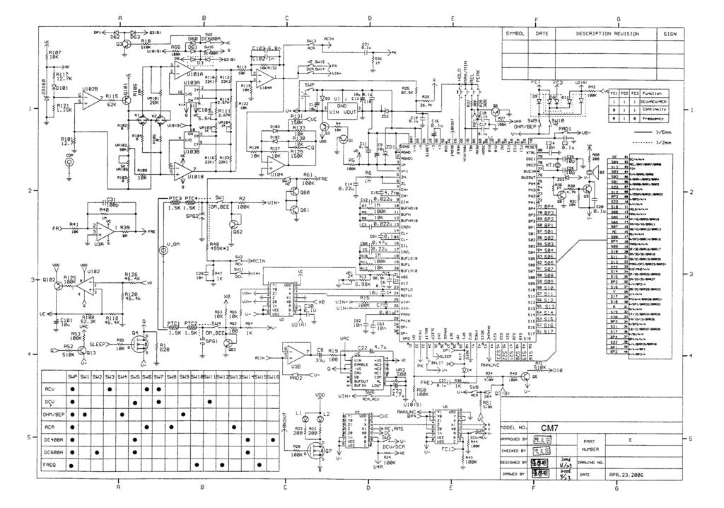
16 Calibration Procedure Recalibrate your meter: It is recommended that the meter may be calibrated once year. Use the following procedure to calibrate the clamp meter. 1. Perform calibration at an ambient temperature and a relative humidity (23ºC±2ºC and RH 80% ). Allow instrument to sit at this temperature for at least thirty minutes. 2. Disconnect the test leads and turn the meter off. Remove the test leads from the front terminals. 3. Position the meter face down. Remove the front screw and back screw from the case bottom. 4. Lift the case bottom from the circuit board. Do not remove the screw from the circuit board. (A) DCV Calibration (Adjust VR1) 1. Set the clamp meter at DCV function. 2. Set the output of DC calibrator for 300V±0.02% and connect to V-Ωand COM input terminals on clamp meter. 3. Using a small flat-tipped screwdriver adjust the potentiometer VR1 until the display reads or Disconnect the DC calibrator for from the clamp meter. (B) ACV Calibration (Adjust VR2) 1. Set the clamp meter at ACV function. 2. Set the output of AC calibrator for 300V±0.02% 50Hz and connect to V-Ωand COM input terminals on clamp meter. 3. Using a small flat-tipped screwdriver adjust the potentiometer VR2 until the display reads or Disconnect the DC calibrator for from the clamp meter. (C) Position Error Calibration (Adjust VR101) 1. Set the clamp meter at DCA function. 2. Flow the current of AC 100A/50Hz around the suitable wire or conductor. 3. Open spring-loaded clamp pressing trigger on the right side of instrument. 4. Position clamp around wire or conductor and release trigger to make sure the clamp is entirely closed. 5. Using a small flat-tipped screwdriver adjust the VR101 until the error is limited under 0.2% while position the. 6. Disconnect the clamp from the wire on conductor. (D) DCA Zero Calibration (Adjust VR102, VR105) 1. Set the clamp meter at DCA function. 2. Using a small flat-tipped screwdriver adjust the VR102 until the display shows 0.0±20 digits. 3. Using a small flat-tipped screwdriver adjust the VR105 until the display shows 0.0±2 digits. 14
17 (E) AC 400A Range Calibration (Adjust VR104) 1. Set the clamp meter at ACA function. 2. Flow the current of AC 360A±0.02%/50Hz around the suitable wire or conductor. 3. Position clamp around wire or conductor and release trigger to make sure the clamp is entirely closed. 4. Reposition the clamp to make the wire or conductor is in the center of the clamp. 5. Using a small flat-tipped screwdriver adjust the potentiometer VR104 until the display reads or Disconnect the clamp from the wire on conductor. (F) AC 1000A Range Calibration (Adjust VR103) 1. Set the clamp meter at ACA function. 2. Flow the current of AC 700A±0.02%/50Hz around the suitable wire or conductor. 3. Position clamp around wire or conductor and release trigger to make sure the clamp is entirely closed. 4. Reposition the clamp to make the wire or conductor is in the center of the clamp. 5. Using a small flat-tipped screwdriver adjust the potentiometer VR103 until the display reads 699 or Disconnect the clamp from the wire on conductor. 15
18
19
20
21
22
23
24
25
26
IDEAL INDUSTRIES, INC. TECHNICAL MANUAL MODEL:
 IDEAL INDUSTRIES, INC. TECHNICAL MANUAL MODEL: 61-352 The Service Information provides the following information: Precautions and safety information Specifications Basic maintenance (cleaning, replacing
BENNING. Service Information MODEL: MM1-1 / MM1-2 / MM1-3
 BENNING MODEL: MM1-1 / MM1-2 / MM1-3 Service Information The Service Information provides the following information: Precautions and safety information Specifications Basic maintenance (cleaning, replacing
IDEAL INDUSTRIES, INC. TECHNICAL MANUAL MODEL: MODEL: Multimeter Service Information
 IDEAL INDUSTRIES, INC. TECHNICAL MANUAL MODEL: 61-340 MODEL: 61-342 Multimeter Service Information The Service Information provides the following information: Precautions and safety information Specifications
# Digital Multimeter
 #61-797 Digital Multimeter - 1 - TABLE OF CONTENTS 1.Introduction Precautions and Safety Information Symbols Safety 2.Specifications General Specifications Electrical Specifications Required Equipment
AC/DC CLAMP METER USER S MANUAL
 AC/DC CLAMP METER USER S MANUAL CONTENTS PAGE SAFETY INFORMATION SYMBOL EXPLANATION SAFETY PRECAUTIONS 1 1 2 MAINTENANCE 3 GENERAL DESCRIPTION 4 PANEL DESCRIPTION 4 OPERATING INSTRUCTIONS... 7 SPECIFICATIONS
USER MANUAL 600A AC Clamp Meter + NCV Model MA610
 USER MANUAL 600A AC Clamp Meter + NCV Model MA610 Additional User Manual Translations available at www.extech.com Introduction Thank you for selecting the Extech MA610 Clamp Meter. This meter measures
ICM 136R Operating Instruction Electrical Clamp-Multimeter
 ICM 136R Operating Instruction Electrical Clamp-Multimeter Safety Information For safe operation of this clamp-multimeter, read these instructions completely before you use it and comply with them fully.
USER'S MANUAL ACDC-100 TRMS ACDC-100. Versatile AC/DC Clamp-on Multimeter Series
 99 Washington Street Melrose, MA 02176 Fax 781-665-0780 TestEquipmentDepot.com USER'S MANUAL ACDC-100 TRMS ACDC-100 Versatile AC/DC Clamp-on Multimeter Series 1 1) SAFETY This manual contains information
AC / DC STROOMTANG MULTIMETER NI 30 AC / DC CLAMP MULTIMETER NI 30. Handleiding / Manual
 AC / DC STROOMTANG MULTIMETER NI 30 AC / DC CLAMP MULTIMETER NI 30 Handleiding / Manual INTRODUCTION 1-1 Unpacking and Inspection Upon removing your new Digital Clamp Multimeter from its packing, you should
MS2030 CAT III 600 V A V AUTO RS232
 MS2030 AC Digital Clamp Meter User s Manual CAT III 600 V AUTO RS232 A V CONTENTS 1.Introduction...1 2.Safety Information...1 2.1 Precautions...1 2.2 Safety Symbols...3 3. Description...4 3.1 Front Panel...4
2,000 counts, 200 Amp ACA/DCA, 600 V ACV/DCV, True RMS, OHMS, Continuity, Hold, Peak Hold FORK CURRENT TESTER. Model : FT-9950
 2,000 counts, 200 Amp ACA/DCA, 600 V ACV/DCV, True RMS, OHMS, Continuity, Hold, Peak Hold FORK CURRENT TESTER Model : FT-9950 Caution Symbol Caution : * Risk of electric shock! Caution : * Do not apply
80i-110s AC/DC CURRENT PROBE
 Table of Contents 3 80i-110s AC/DC CURRENT PROBE Users Manual November 1996 1994, 1996 Fluke Corporation. All rights reserved. All product names are trademarks of their respective companies. Printed in
312, 316, 318. Clamp Meter. Users Manual
 312, 316, 318 Clamp Meter Users Manual PN 1989445 July 2002 Rev.2, 2/06 2002, 2006 Fluke Corporation. All rights reserved. Printed in China. All product names are trademarks of their respective companies.
ET-3888 True RMS Clamp Meter. User Manual
 ET-3888 True RMS Clamp Meter User Manual Index Introduction... 3 Safety Notes... 4 Features... 5 Specifications... 6-8 Instrument Layout... 9 Measurement... 10 Maintenance... 11 Page 2 1. Introduction
INSTRUCTION MANUAL ACD-10 PRO & TRMS PRO
 INSTRUCTION MANUAL ACD-10 PRO & TRMS PRO AMPROBE 1 Congratulations! You are now the owner of an AMPROBE Instrument. It has been quality crafted according to quality standards and contains quality components
Instruction Manual ICM A9 Electrical Clamp Multimeter EN FR IT DE ES
 Instruction Manual ICM A9 Electrical Clamp Multimeter EN FR IT DE ES ICM A9 Warning...................................... Safety.............................................. Read First Safety Information
Model: Pro95 TRUE RMS MILLIAMP CLAMP METER
 Model: Pro95 TRUE RMS MILLIAMP CLAMP METER TABLE OF CONTENTS 1. SAFETY INFORMATION... 1 2. GENERAL SPECIFICATION... 1 3. ELECTRICAL SPECIFICATION... 2 3-1 ACMA MEASUREMENT... 2 3-2 ACA MEASUREMENT...
CONTENTS MS2033A. 1.Introduction Safety Information...01
 MS2033A AC Digital Clamp Meter User s Manual CAT III 600 V CONTENTS 1.Introduction...01 2.Safety Information...01 2.1 Precautions...02 2.2 Safety Symbols...03 3. Description...04 3.1 Front Panel...04 3.2
Instruction Manual IDM 66RT Digital Multimeter
 Instruction Manual IDM 66RT Digital Multimeter EN Warning...................................... Safety sheet.............................................. Read First Safety Information Understand and follow
IDEAL INDUSTRIES, INC. TECHNICAL MANUAL MODEL:
 IDEAL INDUSTRIES, INC. TECHNICAL MANUAL MODEL: 61-920 The Service Information provides the following information: Precautions and safety information Specifications Performance test procedure Calibration
EX360 Series USER MANUAL. True RMS Digital Multimeters. EX360 True RMS Digital Multimeter EX363 True RMS DMM with Temperature and µa AC/DC
 USER MANUAL True RMS Digital Multimeters EX360 Series EX360 True RMS Digital Multimeter EX363 True RMS DMM with Temperature and µa AC/DC EX365 True RMS DMM with 10A AC/DC Current Additional User Manual
99 Washington Street Melrose, MA Fax TestEquipmentDepot.com # # AAC Clamp Meter. Instruction Manual
 99 Washington Street Melrose, MA 02176 Fax 781-665-0780 TestEquipmentDepot.com #61-732 #61-736 400 AAC Clamp Meter Instruction Manual AC HOLD APO DC KMΩ mva WARNING Read First: Safety Information Understand
USER'S MANUAL. ACD-6 Pro. ACD-6 TRMS Pro. Versatile Clamp-on Multimeter Series
 USER'S MANUAL ACD-6 Pro ACD-6 TRMS Pro Versatile Clamp-on Multimeter Series 1 1) SAFETY This manual contains information and warnings that must be followed for operating the instrument safely and maintaining
79/26 Series III Multimeter
 79/26 Series III Multimeter Instruction Sheet W Read First: Safety Information Never use the meter if the meter or test leads look damaged. Be sure the test leads and switch are in the correct position
MODEL: D03128 CLAMP METER
 MODEL: D03128 CLAMP METER 1 CONTENTS Page Number Details 3 Important Safety Information 3 Features 4 Product Overview 5 Switches, Buttons & Input Jacks 5 LCD 6 Specifications 6 Electrical Specifications
Compact Autoranging Clamp Meters. Models (400 A AC), (400 A AC/DC)
, (400 A AC/DC)") User Manual Compact Autoranging Clamp Meters with NIST-Traceable Calibration Models 20250-55 (400 A AC), 20250-56 (400 A AC/DC) THE STANDARD IN PRECISION MEASUREMENT 1065DGMAN_20250-55,-56 DS Clamp Meter
User Manual Compact Autoranging Clamp Meters with NIST-Traceable Calibration Models 20250-55 (400 A AC), 20250-56 (400 A AC/DC) THE STANDARD IN PRECISION MEASUREMENT 1065DGMAN_20250-55,-56 DS Clamp Meter
EX350 Series USER GUIDE. True RMS Digital Multimeters. EX350 True RMS Digital Multimeter EX355 True RMS Digital Multimeter with Temperature
 USER GUIDE True RMS Digital Multimeters EX350 Series EX350 True RMS Digital Multimeter EX355 True RMS Digital Multimeter with Temperature Table of Contents 1. INTRODUCTION 3 2. SAFETY INFORMATION 4 3.
UT207A/208A/209A Operating Manual. Table of Contents
 Table of Contents Title Overview Unpacking Inspection Safety Information Rules for Safe Operation International Electrical Symbols The Meter Structure Display Symbols Functional Buttons The Effectiveness
Instruction Manual ICM 135R Electrical Clamp Multimeter EN FR IT DE ES
 Instruction Manual ICM 135R Electrical Clamp Multimeter EN FR IT DE ES Safety Information For safe operation of this clamp-multimeter, read these instructions completely before you use it and comply with
Instruction Manual ICM 3091N Digital AC Clampmeter EN FR IT DE ES
 Instruction Manual ICM 3091N Digital AC Clampmeter EN FR IT DE ES TABLE OF CONTENTS / EN TITLE TABLE OF CONTENTS PAGE 1. SAFETY INFORMATION... 1 2. TECHNICAL SPECIFICATIONS... 2 3. PARTS & CONTROLS...
ACA LEAKAGE TESTER OPERATION MANUAL. auto range, true rms. Model : DL-9954
 auto range, true rms ACA LEAKAGE TESTER Model : DL-9954 Your purchase of this ACA LEAKAGE TESTER marks a step forward for you into the field of precision measurement. Although this ACA LEAKAGE TESTER is
AC/DC Current Probes Model MR411 Model MR521
 AC/DC Current Probes Model MR411 Model MR521 USER MANUAL OL OL ON ON 600V CAT III - 600A 600V CAT III - 1500A 60A 600A OFF 150A 1500A OFF! OUTPUT: 600A: 1 mv/a 60A: 10 mv/a! OUTPUT: 1500A: 1 mv/a 150A:
OPERATOR S INSTRUCTION MANUAL
 2 OPERATOR S INSTRUCTION MANUAL CLAMP METER HOLD 20 A 200 A 2 A 600 600 LIGHT ON/OFF Digital Clamp Meter 2 20 200 A khz COM CAT.II MAX 600 CONTENTS 1. General instruction.....1 2. Description...1 2.1 Precautions
DIGITAL DUAL DISPLAY AC/DC CLAMP METER MODEL-860A OPERATION MANUAL
 DIGITAL DUAL DISPLAY AC/DC CLAMP METER MODEL-860A OPERATION MANUAL DIGITAL DUAL DISPLAY AC/DC CLAMP METER MODEL-860A TABLE OF CONTENTS TITLE PAGE Safety Information Safety Symbols... 1 Meter Description...
Instruction Manual IDM 98-III & IDM 99-III Digital Multimeters
 Africa 1 & 2 Indianapolis Street Kyalami Business Park Kyalami, Midrand, South Africa Asia 460 Alexandra Road, #15-01A PSA Building Singapore 119963 Instruction Manual IDM 98-III & IDM 99-III Digital Multimeters
KMD-S04 Multímetro de bolsillo
 www.grupotemper.com KMD-S04 Multímetro de bolsillo Table of Contents Title Page Overview ~~~~~~~~~~~~~~~~~~~~~~~~~~~~~~~~~~~~~~~~~~ 3 Unpacking Inspection ~~~~~~~~~~~~~~~~~~~~~~~~~~~~~~~~~ 4 Safety Information
Instruction Manual IDM 61/62T Digital Multimeter EN DE ES IT FR
 Instruction Manual IDM 61/62T Digital Multimeter EN DE ES IT FR Safety Information Read and understand this Instruction Manual completely before using this instrument. Failure to observe the warnings and
IDM 98-III & IDM 99-III Digital Multimeters
 Instruction Manual IDM 98-III & IDM 99-III Digital Multimeters IDM 99-III SECTION 1 SAFETY INFORMATION Safety Information Understand and follow operating instructions carefully. Use the instrument only
User Guide. Digital AC/DC Clamp Meter Model 38394
 User Guide Digital AC/DC Clamp Meter Model 38394 Introduction Congratulations on your purchase of Extech s 38394 AC/DC Clamp Meter. This clamp meter measures AC/DC Current to 600A, DC/AC Voltage, Resistance,
Pen Multimeter. Model
 Pen Multimeter Model 381626 CAUTION: Read, understand and follow all Safety Rules and Operating Instructions in this manual before using this product. This instrument is a 3200 count pen style digital
AMM-1022 Digital Multimeter USER`S MANUAL
 Digital Multimeter USER`S MANUAL www.tmatlantic.com CONTENTS 1. SAFETY INFORMATION.3 2. DESCRIPTION..6 3. SPECIFICATIONS.8 4. OPERATING INSTRUCTION..11 4.1 Voltage measurement...11 4.2 Current measurement
AC/DC Clamp Meter. Owner's Manual. Model No Safety Operation Maintenance Español
 Owner's Manual AC/DC Clamp Meter Model No. 82369 CAUTION: Read, understand and follow Safety Rules and Operating Instructions in this manual before using this product. Safety Operation Maintenance Español
User s Guide. Digital AC/DC Clamp Meter Model 38394
 User s Guide Digital AC/DC Clamp Meter Model 38394 Introduction Congratulations on your purchase of Extech s 38394 AC/DC Clamp Meter. This clamp meter measures AC/DC Current to 600A, DC/AC Voltage, Resistance,
1. SAFETY INFORMATION.1 2. DESCRIPTION SPECIFICATIONS.6 4. OPERATING INSTRUCTION Voltage measurement Current measurement 10
 CONTENTS 1. SAFETY INFORMATION.1 2. DESCRIPTION..4 3. SPECIFICATIONS.6 4. OPERATING INSTRUCTION..9 4.1 Voltage measurement...10 4.2 Current measurement 10 4.3 Resistance measurement...12 4.4 Diode test.12
NOTE: Fully read and understand this manual before using this Digital Multimeter.
 ASTROAI USER MANUAL AUTO RANGING DIGITAL CLAMP METER Thank you for purchasing the Auto Ranging Digital Clamp Meter from AstroAI. The AstroAI Auto Ranging Digital Clamp Meter is designed to be safely and
Digital Clamp Meter Model: &
 Digital Clamp Meter Model: 72-7224 & 72-7226 1 SAFETY INFORMATION Please read these instructions carefully before use and retain for future reference. This meter is designed to meet IEC61010-1, 61010-2-032,
600A Clamp Meters w/tightsight Display
 V 750V #61-764 #61-766 #61-768 600A Clamp Meters w/tightsight Display Instruction Manual 99 Washington Street Melrose, MA 02176 Fax 781-665-0780 TestEquipmentDepot.com CAT.IV 600V CAT.III 1000V 600A 61-766
ETHOS 5030 TRUE-RMS DIGITAL MULTIMETER OPERATION MANUAL
 ETHOS 5030 TRUE-RMS DIGITAL MULTIMETER OPERATION MANUAL 1 1. SAFETY INFORMATION SAFETY SYMBOLS Warning! Dangerous Voltage (Risk of electric shock). Caution! Refer to the user s manual before using this
T5-600/T Electrical Tester
 T5-600/T5-1000 Service Information Introduction This service information sheet provides the following information for the T5-600 and T5-1000 Electrical Testers (hereafter referred to as "the tester").
CM605. User Manual AC/DC LOW CURRENT CLAMP-ON METER ENGLISH
 AC/DC LOW CURRENT CLAMP-ON METER CM605 ENGLISH User Manual Statement of Compliance Chauvin Arnoux, Inc. d.b.a. AEMC Instruments certifies that this instrument has been calibrated using standards and instruments
AC/DC DIGITAL CLAMP METER OPERATION MANUAL
 AC/DC DIGITAL CLAMP METER OPERATION MANUAL HYS005661 A0 ACCESSORIES 6. ACCESSORIES 1) Test Leads: Electric Ratings 1000V 10A 1 pair (set) 2) Operating Manual 1 copy 3) 1.5V AAA Battery 3 piece - - 55 -
AC Clamp Meter + Phase Rotation Tester
 User's Manual AC Clamp Meter + Phase Rotation Tester Model 380974 Hz Introduction Congratulations on your purchase of the Extech 380974 AC Clamp Meter + Phase Rotation Tester. This professional 1000A Clamp
Model True RMS AC/DC 30A Mini Clamp-on Meter. User Guide
 Model 380942 True RMS AC/DC 30A Mini Clamp-on Meter User Guide Introduction Congratulations on your purchase of the Extech Model 380942 DC/AC Clamp Meter. This meter is shipped fully tested and calibrated
1.General instructions Specifications Description...7
 USER S Manual CONTENTS 1.General instructions...1 1.1 Precautions safety measures...1 1.1.1 Preliminary...1 1.1.2 During use...2 1.1.3 Symbols...4 1.1.4 Instructions...5 1.2 Protection mechanisms...6 2.
PEN TYPE DIGITAL MULTIMETER OPERATION MANUAL T8211D
 PEN TYPE DIGITAL MULTIMETER OPERATION MANUAL T8211D T8211D 1 1. SAFETY INFORMATION BE EXTREMELY CAREFUL IN THE USE OF THIS METER. Improper use of this device can result in electric shock or destroy of
400Amp True RMS AC/DC Clamp Meter Model EX613
 User's Guide 400Amp True RMS AC/DC Clamp Meter Model EX613 Introduction Congratulations on your purchase of this Extech EX613 True RMS Clamp Meter. This meter measures AC Current, DC Current, AC/DC Voltage,
DC/AC CLAMP METER ISO-TECH 2000 USERS MANUAL
 DC/AC CLAMP METER ISO-TECH 2000 USERS MANUAL Warnings and Safety symbols: Caution, refer to this manual before using the meter. Dangerous voltages. Meter is protected throughout by double insulation or
DM-45 Digital Multimeter
 INSTRUCTION MANUAL DM-45 Digital Multimeter Read and understand all of the instructions and safety information in this manual before operating or servicing this tool. Description The Greenlee DM-45 Digital
MS8211 DIGITAL MULTIMETER INSTRUCTION MANUAL
 MS8211 DIGITAL MULTIMETER INSTRUCTION MANUAL Ω CONTENTS CONTENTS 1. SAFETY INFORM...1 4.4 Range Transform...10 1.1 Preliminary...1 4.5 Auto Power Off...10 1.2 During use...2 4.6 Preparation For Measurement...11
User's Guide. 800 Amp AC/DC True RMS Clamp Meter. Model EX Washington Street Melrose, MA Phone Toll Free
 User's Guide 99 Washington Street Melrose, MA 02176 Phone 781-665-1400 Toll Free 1-800-517-8431 Visit us at www.testequipmentdepot.com 800 Amp AC/DC True RMS Clamp Meter Model EX730 Introduction Congratulations
IDM 61/62T Instruction Digital Multimeter Manual
 IDM 61/62T Digital Multimeter Instruction Manual # Safety Information Read and understand this Instruction Manual completely before using this instrument. Failure to observe the warnings and cautions in
OPERATOR S INSTRUCTION MANUAL M-2625 AUTO RANGING DIGITAL MULTIMETER
 OPERATOR S INSTRUCTION MANUAL M-2625 AUTO RANGING DIGITAL MULTIMETER with Temperature Probe Copyright 2007 Elenco Electronics, Inc. Contents 1. Safety Information 3,4 2. Safety Symbols 5 3. Front Plate
1587/1577. Insulation Multimeters. Technical Data. Two powerful tools in one.
 Test Equipment Depot - 800.517.8431-99 Washington Street Melrose, MA 02176 - TestEquipmentDepot.com 1587/1577 Insulation Multimeters Technical Data Two powerful tools in one. The Fluke 1587 and 1577 Insulation
CONTENTS. SAFETY PRECAUTIONS: Before use, read the following safety precautions
 CONTENTS [1] SAFETY PRECAUTIONS: Before use, read the following safety precautions 2 [2] APPLICATION AND FEATURES 5 [3] NAME OF COMPONENT UNITS 6 [4] DESCRIPTION OF FUNCTIONS 8 [5] MEASUREMENT PROCEDURE
Dawson DDM190. Digital Multimeter User s Manual
 Dawson DDM190 Digital Multimeter User s Manual TABLE OF CONTENTS LIMITED WARRANTY AND LIMITATION OF LIABILITY... 3 Out of the Box... 3 Accessories.. Error! Bookmark not defined. Safety Information... 7
User Manual Digital Clamp Multimeter. model no.: MSR-C600
 User Manual Digital Clamp Multimeter model no.: MSR-C600 Overview This Operating Manual covers information on safety and cautions. Please read the relevant information carefully and observe all the Warnings
USER MANUAL. Model MA A AC Clamp Meter DMM Model MA445 True RMS 400A AC/DC Clamp Meter DMM
 USER MANUAL Model MA440 400A AC Clamp Meter DMM Model MA443 True RMS 400 AC Clamp Meter DMM Model MA445 True RMS 400A AC/DC Clamp Meter DMM Introduction Thank you for selecting the Extech EX44x Series
200Amp AC Clamp Meter + NCV Model MA250
 User's Guide 200Amp AC Clamp Meter + NCV Model MA250 Introduction Congratulations on your purchase of this Extech MA250 Clamp Meter. This meter measures AC Current, AC/DC Voltage, Resistance, Capacitance,
MS8268 HANDHELD DIGITAL MULTIMETER OPERATOR S INSTRUCTION MANUAL
 MS8268 HANDHELD DIGITAL MULTIMETER OPERATOR S INSTRUCTION MANUAL Table of Contents TITLE PAGE 1. GENERAL INSTRUCTIONS 1 1.1 Precaution safety measures 1 1.1.1 Preliminary 1 1.1.2 During use 2 1.1.3 Symbols
2000 A DCA/ACA CLAMP + DMM,
 2000 A DCA/ACA CLAMP + DMM, true rms DCA/ACA CLAMP METER Model : CM-9930 Your purchase of this DCA/ACA CLAMP METER marks a step forward for you into the field of precision measurement. Although this CLAMP
Model ST Instruction Manual. True RMS Autoranging Digital Multimeter. reedinstruments. www. com
 Model ST-9933 True RMS Autoranging Digital Multimeter Instruction Manual reedinstruments com Table of Contents Safety... 3 Features... 4 Specifications...4-8 Technical...4-5 Accuracy...5-8 Display Description...
AC/DC True RMS Power Clamp Meter ELECTRONIC TEST INSTRUMENTS MODEL 325
 AC/DC True RMS Power Clamp Meter ELECTRONIC TEST INSTRUMENTS MODEL 325 CONTENTS 1. FEATURES... 2 2. Safety precaution... 2 Symbols Description... 3 3. Specifications... 4 4. Electrical Specifications...
400Amp True RMS AC Clamp Meter + NCV
 User Guide 400Amp True RMS AC Clamp Meter + NCV Model MA410T Introduction Thank you for selecting the Extech MA410 Clamp Meter. This meter measures AC Current, AC/DC Voltage, Resistance, Capacitance, Frequency,
Digital Clamp Meter (TRMS) Model : 2727
 Model : 2727") Digital Clamp Meter (TRMS) Model : 2727 Instruction Manual 1. SPECIFICATIONS 1.1 General Specifications Display : 3 ¾ digit liquid crystal display (LCD) with a maximum reading of 3999. Polarity : Automatic,
Digital Clamp Meter (TRMS) Model : 2727 Instruction Manual 1. SPECIFICATIONS 1.1 General Specifications Display : 3 ¾ digit liquid crystal display (LCD) with a maximum reading of 3999. Polarity : Automatic,
Digital Clamp Meter. User Manual
 Digital Clamp Meter User Manual CM240 WWW.OWON.COM.CN Mar. 2016 edition V1.2 Copyright LILLIPUT Company. All rights reserved. The LILLIPUT's products are under the protection of the patent rights, including
CL900. True RMS 1000V 2000A 60MΩ ENGLISH. INSTRUCTION MANUAL 2000A Digital Clamp Meter. Measurement Technology
 ENGLISH INSTRUCTION MANUAL 2000A Digital Clamp Meter True RMS Measurement Technology NON-CONTACT VOLTAGE TESTING INRUSH CURRENT LOW IMPEDANCE DATA HOLD RANGE HOLD AUDIBLE CONTINUITY DIODE TEST CAPACITANCE
User s Guide. 400A AC/DC Clamp Meter. Model MA220
 User s Guide 400A AC/DC Clamp Meter Model MA220 Introduction Thank you for selecting the Extech MA200 AC/DC Clamp Meter. This meter measures AC/DC Current, AC/DC Voltage, Resistance, Capacitance, Frequency,
SAFETY PRECAUTIONS: Before use, read the following safety precautions
 [1] SAFETY PRECAUTIONS: Before use, read the following safety precautions This instruction manual explains how to use your multimeter CD731, CD751 safely. Before use, please read this manual thoroughly.
OPERATOR S INSTRUCTION MANUAL DIGITAL MULTIMETER
 OPERATOR S INSTRUCTION MANUAL DIGITAL MULTIMETER SAFETY INFORMATION This multimeter has been designed according to IEC 1010 concerning electronic measuring instruments with an overvoltage category (CATⅡ)
CLAMP-ON METER 670. User Manual
 CLAMP-ON METER 670 675 E N G L I S H User Manual Certificate of Compliance Chauvin Arnoux, Inc. d.b.a. AEMC Instruments certifies that this instrument has been calibrated using standards and instruments
Electrical Multimeter
 113 Electrical Multimeter Instruction Sheet Safety Information A Warning statement identifies hazardous conditions and actions that could cause bodily harm or death. A Caution statement identifies conditions
AC/DC Current Oscilloscope Probe Model SL261
 AC/DC Current Oscilloscope Probe Model SL261 USER MANUAL I ZERO 100 mv/a 10 mv/a OFF Statement of Compliance Chauvin Arnoux, Inc. d.b.a. AEMC Instruments certifies that this instrument has been calibrated
OPERATOR S INSTRUCTION MANUAL
 OPERATOR S INSTRUCTION MANUAL AUTO-RANGE DUAL DISPLAY CONFORMED IEC1010 DIGITAL MULTIMETER CONTENTS PAGE SAFETY INFORMATION..... DESCRIPTION.. OPERATING INSTRUCTION.. SPECIFICATIONS.... ACCESSORIES. BATTERY
INSTRUCTION MANUAL DIGITAL MULTIMETER
 INSTRUCTION MANUAL DIGITAL MULTIMETER 600 OFF 600 20 2m 2 20m m m 2M 10A k 20k 2k O C NPN PNP hfe E B C E 10A DC 10A MAX UNFUSED MAX 600V COM V ma ma MAX FUSED CAT II 600V Thanks for buying our products,
User Manual. Solar Power Clamp. 99 Washington Street Melrose, MA Phone Toll Free
 User Manual 99 Washington Street Melrose, MA 02176 Phone 781-665-1400 Toll Free 1-800-517-8431 Visit us at www.testequipmentdepot.com Solar Power Clamp Warning Safety sheet....................................................................................
DM-46 Instruction Manual
 Auto Meter Products Inc. Test Equipment DM-46 Instruction Manual Automotive Multimeter and Inductive Amp Probe The DM-46 is the auto industry s answer to pocket portability in a 20 2650-1552-00 3/8/11
User s Guide. 400A AC/DC Clamp Meter. Model MA Washington Street Melrose, MA Phone Toll Free
 User s Guide 99 Washington Street Melrose, MA 02176 Phone 781-665-1400 Toll Free 1-800-517-8431 Visit us at www.testequipmentdepot.com 400A AC/DC Clamp Meter Model MA220 Introduction Thank you for selecting
FlexProbe FLEXIBLE AC CURRENT PROBE. User Manual. FlexProbe ON OL 1000V CAT III 300A 3000A OFF
 I N S T R U M E N T S FLEXIBLE AC CURRENT PROBE FlexProbe 24-3001 ON OL 1000V CAT III 300A 3000A OFF FlexProbe 24-3002 E N G L I S H User Manual Statement of Compliance Chauvin Arnoux, Inc. d.b.a. AEMC
Analog Technologies. Multimeter 15B and17b
 Figure 1. The Photo of Actual 17B Figure 2. The Photo of Actual 15B FEATURES Maximum Voltage between Any Terminal and Earth Ground: 1000V Temperature Coefficient: 0.1 (specified accuracy)/ (28
User s Manual. MiniTec TM Series. Model MN26 (Model MN26T includes temperature probe) Mini Autoranging MultiMeter
 Mini Autoranging MultiMeter") User s Manual MiniTec TM Series Model MN26 (Model MN26T includes temperature probe) Mini Autoranging MultiMeter Introduction Congratulations on your purchase of Extech s MN26 Autoranging Multimeter. This
User s Manual MiniTec TM Series Model MN26 (Model MN26T includes temperature probe) Mini Autoranging MultiMeter Introduction Congratulations on your purchase of Extech s MN26 Autoranging Multimeter. This
USER MANUAL. Model MA A AC Mini Clamp-on Meter. Additional User Manual Translations available at
 USER MANUAL Model MA150 200A AC Mini Clamp-on Meter Additional User Manual Translations available at www.extech.com Introduction Thank you for selecting the Extech MA150 AC Mini Clamp Meter. This device
Pen-type DIGITAL MULTITESTER
 BST-MT267 Pen-type DIGITAL MULTITESTER INSTRUCTION MANUAL Index 1. Introduction... 2. Safety Notes... 3. Features... 4. Specifications... 5. General... 6. Instrument Layout... 7. Measurement... 8. Maintenance...
1587/1577 Insulation Multimeters
 1587/1577 Insulation Multimeters Technical Data Two powerful tools in one. The Fluke 1587 and 1577 Insulation Multimeters combine a digital insulation tester with a full-featured, true-rms digital multimeter
DVM645BI BENCH MULTIMETER TAFELMULTIMETER MULTIMETRE DE TABLE BANCO MULTÍMETRO TISCHMULTIMETER. User Manual. Gebruikershandleiding
 BENCH MULTIMETER TAFELMULTIMETER MULTIMETRE DE TABLE BANCO MULTÍMETRO TISCHMULTIMETER User Manual Gebruikershandleiding Manuel d'utilisation Gebrauchsanleitung Introduction BENCH MULTIMETER This manual
Mini Clamp Meter Model:
 Mini Clamp Meter Model: 72-2985 1 CONTENTS Page Number Details 2 What s Included 3 Important Safety Information 3 Technical Specification 4 Product Overview 5 LCD Overview 6 Operation - AC/DC Voltage Measurement
DM-46 Instruction Manual
 Test Equipment Auto Meter Products Inc. 413 West Elm Street Sycamore, IL 60178 Service (815) 899-0801 Toll Free (866) 883-TEST (8378) www.autometer.com/test DM-46 Instruction Manual Automotive Multimeter
ATK Clamp Meter
 ATK-2209 Clamp Meter User s Manual Title CONTENTS Page I. SAFETY INFORMATION... 1 II. TECHNICAL SPECIFICATIONS... 2 2-1 Environment Conditions... 2 2-2 Maintenance... 2 2-3 Features... 2 2-4 General Specifications...
HANDHELD DIGITAL MULTIMETER OPERATOR S INSTRUCTION MANUAL
 HANDHELD DIGITAL MULTIMETER OPERATOR S INSTRUCTION MANUAL GENERAL INSTRUCTIONS This instrument complies with IEC 1010-1 (61010-1@IEC: 2001), CAT. II 1000V and CAT. III 600V overvoltage standards. See Specifications.
MW3105 DIGITAL CLAMP MULTIMETER
 MW3105 DIGITAL CLAMP MULTIMETER 2 M MW3105 A 01 INTRODUCTION 1.1 - Unpacking and inspection Upon removing your new Digital Clamp Meter from its packing, you should have the following items: 1. Digital
Model UT201/202: OPERATING MANUAL. Table of Contents
 Table of Contents Title Overview Unpacking Inspection Safety Information Rules For Safe Operation International Electrical Symbols The Meter Structure Rotary Switch Functional Buttons The Effectiveness