Wireless Bluetooth Controller for DC Motor
|
|
|
- Conrad Warren
- 6 years ago
- Views:
Transcription
1 Wireless Bluetooth Controller for DC Motor ECE 445 Final Report May 1, 2007 Team Members: Abhay Jain Reid Vaccari TA: Brian Raczkowski Professor Gary Swenson
2 TABLE OF CONTENTS 1. INTRODUCTION Motivation Objectives Goals Functions DESIGN Block Diagram Block / Subproject Descriptions PC / User Input USB Bluetooth Adapter BlueSMIRF Bluetooth Module Microcontroller V Battery Voltage Regulators H-Bridge Vdc Motor Performance Requirements DESIGN VERIFICATION Testing Procedures and Results PC to Bluetooth Adapter Module Control Unit H-Bridge Vdc Motor Thoroughness Tolerance Analysis COST ANALYSIS Labor Parts CONCLUSIONS Accomplishments Uncertainties Ethical Considerations Future Work Alternatives APPENDIX Current Analysis In Motor Current vs. Applied Motor Voltage Plots H-Bridge Simulation REFERENCES
3 I) Introduction 1.1) Motivation We were drawn to the idea of this project from a similar idea in the suggested Power project ideas as provided by the TAs. We found it to be particularly interesting because we are both interested in power and the idea of a wirelessly controlled motor seemed fascinating to us. We also feel that this could be a very practical idea as wireless technology is becoming increasingly more available. So, being able to control a motor through a wireless connection on a laptop could considerably enhance flexibility. The idea of using Bluetooth technology was also a big motivation for our project as we are both familiar with the technology but are very interested in obtaining a much more comprehensive understanding of how it works. 1.2) Objectives 1.2.1) Goals The goal of this project was to design a controller that would be able to run a DC motor wirelessly using Bluetooth technology. This controller functions through a software application on a laptop or desktop computer from within 60 feet of the motor ) Functions The motor has the functionality to start, stop, accelerate, and decelerate through the push of commands on the computer. The software is a simple one-screen Windows based application. Benefits: Practical Provides Flexibility Economical User-friendly Can be ran from any PC running Windows Features: Windows based Battery operated Wireless control via Bluetooth Adjustable Speed User has ability to start, stop, accelerate or decelerate the DC motor II) Design Over the course of time between the proposal and the design review, the design was modified to be more efficient by removal of the DC to DC step down converter. The purpose of this was to physically alter the amount of voltage that reaches the motor using analog components. However, it was proven to be unnecessary as the PWM module can adopt this functionality by altering the pulse width that reaches the h-bridge, and thus the 3
 Updated Block Diagram 2.2) Block / Subproject Descriptions 2.2.1) PC / User Input: This block is the only point where the system accepts user input.")
4 duty cycle, translating to the percent voltage that reaches the motor. Thus, the block diagram and other relevant design specifications have been updated. This design remained unchanged for the remainder of the project. 2.1) Updated Block Diagram 2.2) Block / Subproject Descriptions 2.2.1) PC / User Input: This block is the only point where the system accepts user input. It is a Windows-based software application that can be run on any Windows PC or laptop. Here the user is able to manipulate the various functions of the motor; run, stop, accelerate, decelerate and switch directions using easy to learn onscreen controls. The software was programmed using Visual C++ programming language. A control scheme is generated to send out a serial control signal that will represent the desired speed of the motor, in RPMs. The motor used has a gear ratio of 65.5:1, and both speeds are displayed on the screen. The speed is set relevant to the lower geared side of the motor, thus the user has the option of setting the speed from 0-95 RPM. Once the user has selected a speed, it is outputted to the Bluetooth via a serial port connection. This is a string representation of the integer. If the motor is chosen to be operated in the counter-clockwise direction, the string outputted is just the speed. 4

5 However, if the direction chosen is clockwise, then a - character is appended to the beginning of the control string. Thus, operating at 50 RPM in the CCW direction has a control string of 50, whereas in the CW direction it would be ) USB Bluetooth Adapter (SKU#: RF-BT-USB): To bridge the connection between the PIC and the PC, there are Bluetooth modules connected to both sides. The PC side is implemented using this common adapter that lets a Bluetooth connection be made as a serial link. The USB adapter can be installed easily in Windows, just as any other USB device would. The signals are received and manipulated from the motor control software ) BlueSMIRF Bluetooth Module (WML-C40): This is the other end of the Bluetooth wireless connection; it is the module that receives the wireless signals from the USB transmitter and sends them to the control unit. It is capable of communication via UART, PCM and USB interfaces, and we utilize the UART (serial) communication. The control signals are received from the USB Bluetooth transmitter and pass through the 5
6 WML-C40 to the PIC16F877 microcontroller via TX / RX serial communication which are pins 10 and 11 on the module. It is fed with 5 V from the regulator, which it internally steps down to 3.3 V ) Microcontroller (PIC16F877): The control unit consists of the PIC microcontroller and the pulse width modulator. The PIC16F877 was chosen because it was available in the ECE445 lab and it included two onboard PWMs. The PWMs are used to control the duty cycle of the motor by regulating the power output. Once the control signal from the PC reaches the PIC through the Bluetooth transmitters, its values are interpreted in the program and generate the necessary outputs. The PIC is programmed in a simplified C instruction set. The duty cycle of the motor is set by changing the length of the pulse that the PWM outputs. 6
7 There are several options for control that could have been explored, including feedback or feed forward. We chose a feed forward control scheme to be used in applications where the load is already known. The PIC has a clock of 20 MHz provided by an external Fox F1100E oscillator. For the PWM operations, this is stepped down to 16 khz. At 16 khz, 416 us would representative half the period and a duty cycle of 50%. To translate this so an integer to set the duty cycle as in the program, we use the equation: = E6 Setting the PWM duty cycle to 520 should then allow the PWM to output a duty cycle of 50%, but when the output was measured with an oscilloscope, it was seen to give a duty cycle of 52%. This also held true for other values tried, so there is a 10:1 ratio from duty cycle variable (in integer form) to the actual produced duty cycle (in percent). To implement this, the motor was run at no-load to measure what voltages were provided by various duty cycles. These voltages correspond to speeds, so we can construct a relationship between actual speed and the duty cycle. The data from this test are as follows in Table 1: Duty Cycle Speed (RPM) Using the most extreme data points, we calculated a linear relationship between speed and duty cycle. Y = Mx + B Duty cycle = M(speed) + B M = (y 2 y 1 ) / (x 2 x 1 ) = ( )/(108-2) = 7.92 B = 950 (7.92*108) = Duty Cycle = 7.92(speed) This equation was used to set the duty cycle, based on the speed that the user specified. This had to be altered slightly for each direction, due to different coefficients of friction in either direction. A plot of this linear fit is seen below. 7
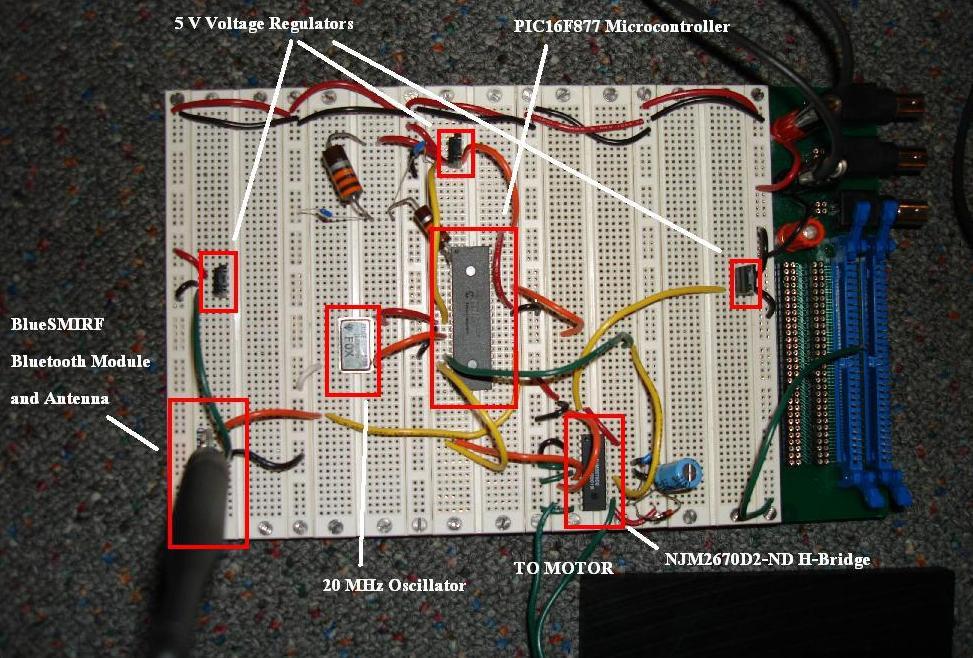
8 Speed vs. Duty Cycle y = x Duty Cycle Speed (RPM) 2.2.5) 12 V Battery (BP5-12-T2): This is the power supply for the circuit. It is used to power the motor, as well as the logic chips of the system. The h-bridge, Bluetooth module and PIC microcontroller are supplied with a lower voltage, scaled down by voltage regulator to 5 V. The battery is connected to the motor through the h-bridge, which dictates when and how much (in junction with the PWM) voltage reaches the motor leads. A 12 V lead acid battery was used ) 5 V Voltage Regulators (LM7805A): The voltage regulators are used to convert the 12 V voltage from the battery down to the appropriate supply voltages for each component. We decided to use the voltage regulators after our original voltage divider circuit (consisting of two resistors) was unable to protect our circuit from a voltage spike, which resulted in our original Bluetooth module receiving too much voltage, thus ruining it. Three separate regulators were used to provide the 5 volts needed to each of the h-bridge, Bluetooth module and microprocessor ) H-Bridge (NJM2670D2-ND): The purpose of the h-bridge is to allow the user to choose the direction the motor rotates in, as well as bring the motor to a complete stop. It consists of four MOSFET transistors operating as switches. Two MOSFETS are connected to each lead of the motor, one connecting the lead to V CC (12 V from the battery) and the other connecting the lead to system ground. When the top switch on one side is on at the same time as the bottom switch on the opposite side, current flows in that direction and causes the motor to turn. When these are turned off and the other two switches turned on, current flows between those two instead and the motor rotates in the opposite direction. The chip chosen is the NJM2670D2-ND PWM Dual H-Bridge Driver. The two inputs to the H-bridge, IN1 and IN2, receive their signal from the PWMs. The duty cycle of the PWM signal specifies how long the MOSFET switches are active, thus controlling the average voltage that reaches the motor, which in turn controls the speed. 8
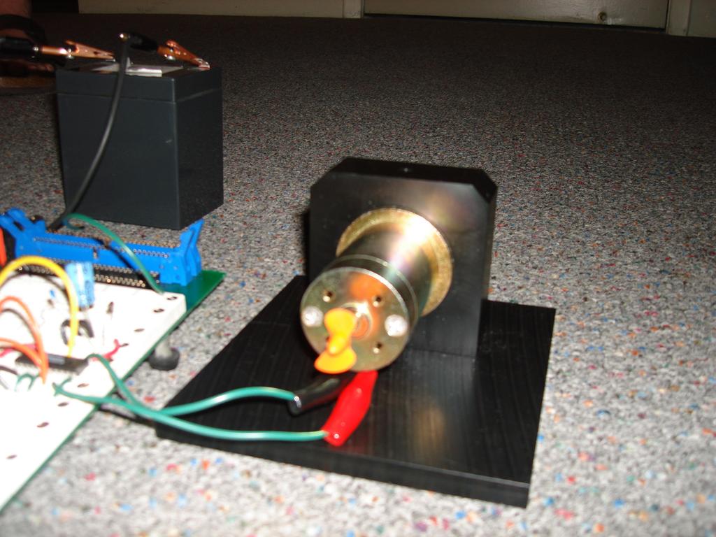
9 If the motor is to turn in the clockwise direction, then the duty cycle that reaches IN2 is set to 0, and IN1 receives the duty cycle for the given speed, and vice versa. Before physicall implementing the H-bridge, we tested its functionality using a PSPICE simulation. This simulation diagram and resulting waveforms are attached in the Appendix, section ) 12 Vdc Motor (GM9434G807): This is a Pittman 12 V permanent magnet geared DC motor. It will be powered by the 12 V lead acid battery, from which the voltage level that reaches the motor will be controlled via the control unit, through the h-bridge. It is capable of rotating in both directions, which is controlled with the h-bridge. The motor has a gear ratio of 65.5: 1. In order to isolate the supply voltage, protective capacitors are added in parallel with the motor, as well as a zener diode to regulate the voltage. 9
10 Full Schematic 2.3) Performance Requirements Maximum input voltage of 12 V DC Output voltage varying from 0 12 V DC depending on desired speed Adjustable speed from 0 to 93.9 RPM on lower geared side Adjustable speed from 0 to 6222 RPM on load side Maximum rated motor torque of 2.12 N m Motor can turn in both directions Can handle continuous motor load up to 15 W 10
11 Wireless control via Bluetooth up to 60 feet Motor control software runs on any Windows-based PC III) Design Verification 3.1) Testing Procedures and Results 3.1.1) PC to Bluetooth Adapter Module In order to test the connection from the GUI and USB Transmitter to the WML- C40 on the motor side, we first connected the RX and TX of the WML-C40 to each other, so that the chip receives a signal from the transmitting PC and sends it back. This is used to verify that both the RX and TX configurations are working properly. Using the application HyperTerminal, ASCII characters are typed with no local echo on, so that if they are not sent back by the Bluetooth module, they will not be displayed on the screen. By doing this test, we were able to verify that the Bluetooth module was correctly receiving and transmitting the control signal. Once this was working, we connected the TX of the Bluetooth module to a RS232 level translator, which was then connected to a second PC running HyperTerminal. This was used to represent the PIC. To make sure the signal would be correctly received by the PIC, we ran the GUI, executing all the commands, and observed the speed received on the second PC. We could observe the speed changing in accordance with what was being selected on the GUI, verifying the output was correct ) Control Unit The PIC microprocessor and PWM combination were tested in several steps. Various serial inputs were sent to the PIC using HyperTerminal and our motor control GUI, and outputs were assigned based on input. The serial data had to be translated from a string variable to an integer, so that it could be numerically evaluated. The integer equivalent of the string was set by the string character s ASCII decimal value, which means we had to translate the ASCII decimal equivalent to it s integer value. Once a speed integer was produced, we ran a test by first turning one output high if the incoming speed was greater then zero, and a second output high if the speed was less then zero. We were able to accomplish this, meaning we could run the motor in both directions at this point, but not at variable speeds. The onboard PWMs were tested by assigning various duty cycles to the outputs, and observing the resulting waveform with an oscilloscope ) H-Bridge The H-bridge was tested first by hardwiring one of the two input pins to ground, and the other to 5 volts. Depending on which orientation they were connected in, the H- bridge would either produce 12 V or 12 V to the motor leads. This is how the direction of the motor is determined. Once this was verified, we were able to test the H-bridge by wiring it to the outputs of the PIC. Using the setup before the PWMS were implemented, we were able to observe the H-bridge outputting 0 V, 12 V and 12 V depending on what was specified 11
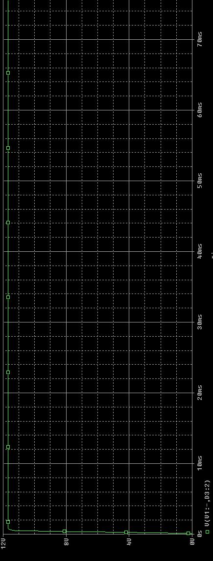
12 by the user input. After this was functional, we were able to test it with the PWM inputs instead, allowing for variable speed control ) 12 Vdc Motor The motor was first tested by connecting 12 V and 12 V to the motor leads, to verify that it ran in both directions. Once that was verified, we were able to connect it to the output of the H-bridge, and observe the resulting motor activity for a given user input. 3.2) Thoroughness Since all of our parts function correctly independently we were able to determine that the product will meet the performance requirements. We knew that if the product did not function correctly, the problem would be due to implementation and connection error and should be relatively easy to identify and resolve. 3.3) Tolerance Analysis Since the DC to DC step down converter was removed from the design, the most important aspect is the PWM that is built into the PIC. This unit is especially important, as it is the one that controls the exact amount of power that the motor receives; thus controlling the functionality of the motor. Making sure that the PWM is delivering the correct duty cycle to the h-bridge ensures that the user will be able to control the exact speed of the motor. This was tested by defining different duty cycles and making sure that these are in fact the signal that reaches the h-bridge, and once that is confirmed, making sure these duty cycles correspond to the proper output voltage. More specifically, a known duty cycle was applied, and an oscilloscope was used to view the waveform from the PWM to the h-bridge to make sure that the correct duty cycle was observed. When that was working properly, the oscilloscope was placed over the motor leads to make sure it was receiving the corresponding correct voltage. Seen below are two control signals from the PWM output to the H-bridge input. These are 5 volt logic, and have a duty cycle corresponding to the requested speed. These duty cycles were determined to provide the requested speed by the function tests that were described above. Control Signal from PIC to H-bridge at 48 RPM 12
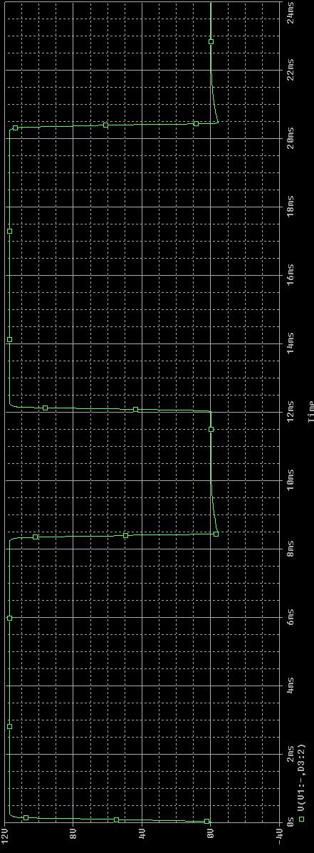
13 Control Signal from PIC to H-bridge at 5 RPM To verify that the correct voltage is provided to the motor, oscilloscope plots of the motor voltage are also provided. As can be seen, these have close to the same duty cycle as the control signals above, but now are on a 12 V scale. Motor Voltage at 48 RPM Motor Voltage at 5 RPM 13
14 IV) Cost Breakdown 4.1) Labor Costs: The provided formula for labor cost, per person, is: Labor Cost Per Person = Hourly Salary * Actual Hours * 2.5 Over the course of the project, there were a total of 394 man hours worked between both team members. The estimated wage for this is $25 / hour. So the total labor cost, including both team members, is 394 * 25 * 2.5 Total Labor Cost: $24, ) Part Costs: Part Model # Manufacturer Price Quantity Total Price Wireless Receiver for PC 2.4GHz Duck Antenna BlueSMIRF WML-C40 Module H-Bridge 14 Total Price (if 10,000 purchased) WRL Sparkfun $ $16.95 $13.56 WRL Sparkfun $ $7.95 $6.36 WRL Mitsumi $ $64.95 $51.96 NJM2670D2- ND TI $ $4.83 $ V Battery BP5-12-T2 B&B Battery $ $15.93 $ K Ω TK20P500RJE Ohmite Mfg. $ $8.42 $3.78 Resistor 20 MHz F1100E Fox $ $2.27 $1.75 Oscillator 5V Regulator LM7805A Fairchild $ $1.17 $0.93 PIC PIC16F877 Microchip $10 1 $10 $ V DC Motor GM9434G807 Pittman $ $ M Ω CRCW08054M Vishay/Dale $ $0.08 $0.006 Resistor 70JNEA 1.8 M Ω CRCW08051M Vishay/Dale $ $0.04 $0.005 Resistor 80FKEA 3.3 M Ω CRCW08053M Vishay/Dale $ $0.04 $0.005 Resistor 30FKEA 100 K Ω CRCW Vishay/Dale $ $0.11 $0.027 Resistor KFKEA 30 K Ω CRCW Vishay/Dale $ $0.04 $0.005 Resistor K0FKEA 10 K Ω Resistor CRCW K0FKEA Vishay/Dale $ $0.11 $0.027
15 Resistor K0FKEA 1 uf BC $ $0.50 $0.22 Capacitor Components 100 nf UVR1H0R1MD Nichicon $ $0.20 $0.035 Capacitor D 47 uf BC $ $1.47 $0.63 Capacitor Components Zener Diode 2EZ12D5D041 MicroSemi $ $1.42 $1.09 Diode 1n4004 General Semiconductor $ $0.05 $0.028 Total Part Cost: $ Total Cost (Labor + Parts) = $24,781 Total Part Cost (if 10,000 purchased): $ Total Cost (Labor + Parts (if 10,000 purchased)) = $24,739 V) Conclusion 5.1) Accomplishments With our allotted time this semester, we were able to successfully integrate everything we promised in our design proposal. The user was successfully able to control the motor wirelessly from the GUI running on a laptop. The user was able to start, stop, accelerate and decelerate the motor by setting the speed (in RPM, referenced to the lower geared side). The motor was able to run 0-95 RPM on the lower geared side, and RPM on the load side. The direction of the motor was also selectable, using the CW and CCW buttons. This functionality all worked as desired. When the motor was running and the user chose to switch directions, the motor slowly ramped down its speed to zero, then switched directions and ramped back up to the desired speed. The same ramping effect was used when Stop was selected, to bring it slowly to 0 RPM. The purpose of this was to protect the motor from sudden voltage and speed changes. We were able to run the motor at a maximum of 15 W, which was the desired range. The desired torque of 2.12 N-m could not be achieved however, because we were limited by our H-bridge output current of 1.2 A. We were able to achieve a maximum of torque of 1.33 N-m. 5.2) Uncertainties With the feed forward control approach that was used, we remain uncertain how accurate the speed control would be for an unknown or varying load. 15
16 Another uncertainty would be how the circuit would respond if the load exceeded the maximum load of 15 W. We did not observe this because we did not want to exceed the rated currents and destroy our chips; however it is very possible that this could happen in a practical application. 5.3) Ethical Considerations As our design was not constructed entirely from scratch and used existing products purchased from suppliers, we may need to have their consent before commercially marketing our product. Other then that, this project does not raise any other ethical issues. 5.4) Future Work Once we had achieved all the aspects that we had originally promised in our Design Review, we decided to take the next step and incorporate a feedback loop into our circuit. The purpose of this was to confirm that the actual speed achieved by the motor matched the desired speed specified by the user. If not, a correction algorithm would be implemented, to compensate and reduce the error. The practical applications for such a circuit with speed feedback would be a situation where the load is varying or unknown. One example of this would be an off-road remote control car that encounters various terrains. With a feed forward loop, an increase in load would not be compensated for, and thus the desired speed would not be achieved. However with feedback, it would be compensated for, and the voltage to the motor could be increased to achieve the desired speed. We were able to begin implementation of this feedback control, by measuring actual RPMS achieved by the motor using a rotary encoder that we designed. We were then able to send this signal to the microcontroller and read it, but did not have enough time to finish implementing the code. This would a great place for someone picking the project up to start with. 5.5) Alternatives An alternative to using the PWM outputs to set the duty cycle of the motor, a buck converter circuit could have been constructed. However, we found that the PWM technique was much more efficient because all the scaling could be done digitally in the PIC code, rather then via analog using a buck converter. This simplifies the circuit greatly. An H-bridge with a higher current rating could also have been used, in order to allow a higher input current to the motor, thus increasing the maximum torque and power produced. Lastly, a battery with a higher Amperes / Hour rating could be chosen which would increase the length of time the circuit can be run. This would be very useful for many applications, such as the remote control car. 16
17 VI) Appendix 6.1) Current Analysis Pin Currents Measurement DC Motor No-Load Current (Measured) DC Motor No-Load Current (Spec Sheet) Motor Peak Current Maximum Current Output from H-Bridge H-Bridge High Level Logic Input Current H-Bridge Max Output Current WML-C40 Current Consumption PIC16F877 I/O Pin Current (Source and Sunk) Value 0.45 A 0.33 A 14.5 A 3 A 2 to 50 ua, 10 ua typical 1.2 A 90 ma 25 ma 6.2) Input Motor Current vs. Applied Motor Voltage Plots DC Motor Input Current (No-Load) Motor Voltage Measured Input Current (A) 0 V V V V V V V V V V V V V V V V V V V V V V V V V
18 Motor Voltage vs. Input Current Input Current (A) (A) Applied DC Motor Voltage (12 V) DC Motor Input Current (Max Load) Motor Voltage Measured Input Current (A) 0 V V V V V V V V V V V V V V V V V V V V V V V V V
19 Motor Voltage vs. Input Motor Current (With Load) Input Current (A) (A Applied DC Motor Voltage (12 V) 6.3) H-Bridge Simulation A simulation of the H-bridge using PSPICE is seen on the next page. This gave a verification that the H-bridge chip would respond in the correct manner. Using pulse voltage sources to model the duty cycle signal from the PWM, the pulse width can be changed to different percentages of the total period of the signal, which in turn changes the average voltage that the motor receives. With a PW of 12 ms and a period of 12 ms, the motor gets the full 12 volts, as seen in the first simulation PSPICE plot. However, if the period remains at 12 ms and the PW is changed to 8 ms (or two thirds), it can be seen that the average of the DC voltage that reaches the motor is 2/3 of the total 12 V. This is seen in the second plot. 19
20 H-Bridge PSPICE Simulation 20
21 21
22 22
23 23
24 REFERENCES [1] Microchip Technologies, Inc, PIC16F87X Data Sheet, [Online Document], 2001, [cited 4 March 2007], Available HTTP: [2] New Japan Radio Co., Ltd., Dual H Bridge Driver. [Online Document], 3 Oct 2003, [cited 25 Feb 2007], Available HTTP: [3] Mitsumi Electric, Bluetooth Module, WML-C40 Class 1, [Online Document], [cited 2 Feb 2007], Available HTTP: [4] PennEngineering Motion Technologies, Pittman, LO-COG DC Gearmotors, [Online Document], 2003, [cited 13 Feb 2007], Available HTTP: 24
Lock Cracker S. Lust, E. Skjel, R. LeBlanc, C. Kim
 Lock Cracker S. Lust, E. Skjel, R. LeBlanc, C. Kim Abstract - This project utilized Eleven Engineering s XInC2 development board to control several peripheral devices to open a standard 40 digit combination
Pulse-Width-Modulation Motor Speed Control with a PIC (modified from lab text by Alciatore)
") Laboratory 14 Pulse-Width-Modulation Motor Speed Control with a PIC (modified from lab text by Alciatore) Required Components: 1x PIC 16F88 18P-DIP microcontroller 3x 0.1 F capacitors 1x 12-button numeric
Laboratory 14 Pulse-Width-Modulation Motor Speed Control with a PIC (modified from lab text by Alciatore) Required Components: 1x PIC 16F88 18P-DIP microcontroller 3x 0.1 F capacitors 1x 12-button numeric
HIGH BRIGHTNESS REMOTE CONTROLLED WHITE LED BULB. Tzong-Yu Chan Justin Czarnowski ECE 445, SENIOR DESIGN PROJECT SPRING 2009.
 HIGH BRIGHTNESS REMOTE CONTROLLED WHITE LED BULB By Tzong-Yu Chan Justin Czarnowski ECE 445, SENIOR DESIGN PROJECT SPRING 2009 TA: Paul Rancuret 5/5/2009 Project No. 27 1 ABSTRACT The goal of our project
ECE 511: FINAL PROJECT REPORT GROUP 7 MSP430 TANK
 ECE 511: FINAL PROJECT REPORT GROUP 7 MSP430 TANK Team Members: Andrew Blanford Matthew Drummond Krishnaveni Das Dheeraj Reddy 1 Abstract: The goal of the project was to build an interactive and mobile
o What happens if S1 and S2 or S3 and S4 are closed simultaneously? o Perform Motor Control, H-Bridges LAB 2 H-Bridges with SPST Switches
 Cornerstone Electronics Technology and Robotics II H-Bridges and Electronic Motor Control 4 Hour Class Administration: o Prayer o Debriefing Botball competition Four States of a DC Motor with Terminals
PreLab 6 PWM Design for H-bridge Driver (due Oct 23)
") GOAL PreLab 6 PWM Design for H-bridge Driver (due Oct 23) The overall goal of Lab6 is to demonstrate a DC motor controller that can adjust speed and direction. You will design the PWM waveform and digital
GOAL PreLab 6 PWM Design for H-bridge Driver (due Oct 23) The overall goal of Lab6 is to demonstrate a DC motor controller that can adjust speed and direction. You will design the PWM waveform and digital
EE152 Final Project Report
 LPMC (Low Power Motor Controller) EE152 Final Project Report Summary: For my final project, I designed a brushless motor controller that operates with 6-step commutation with a PI speed loop. There are
EE 314 Spring 2003 Microprocessor Systems
 EE 314 Spring 2003 Microprocessor Systems Laboratory Project #9 Closed Loop Control Overview and Introduction This project will bring together several pieces of software and draw on knowledge gained in
WIRELESS ELEVATOR REMOTE CONTROL. Patrick Goh Hamed Asghari ECE 445, SENIOR DESIGN PROJECT. Spring TA: Dwayne Hagerman. Project No.
 WIRELESS ELEVATOR REMOTE CONTROL By Patrick Goh Hamed Asghari ECE 445, SENIOR DESIGN PROJECT Spring 2007 TA: Dwayne Hagerman May 1, 2007 Project No. 16 ABSTRACT The Wireless Elevator Remote Control (WERC)
Project Final Report: Directional Remote Control
 Project Final Report: by Luca Zappaterra xxxx@gwu.edu CS 297 Embedded Systems The George Washington University April 25, 2010 Project Abstract In the project, a prototype of TV remote control which reacts
DC Motor and Servo motor Control with ARM and Arduino. Created by:
 DC Motor and Servo motor Control with ARM and Arduino Created by: Andrew Kaler (39345) Tucker Boyd (46434) Mohammed Chowdhury (860822) Tazwar Muttaqi (901700) Mark Murdock (98071) May 4th, 2017 Objective
Project Proposal. Low-Cost Motor Speed Controller for Bradley ECE Department Robots L.C.M.S.C. By Ben Lorentzen
 Project Proposal Low-Cost Motor Speed Controller for Bradley ECE Department Robots L.C.M.S.C. By Ben Lorentzen Advisor Dr. Gary Dempsey Bradley University Department of Electrical Engineering December
DC motor control using arduino
 DC motor control using arduino 1) Introduction: First we need to differentiate between DC motor and DC generator and where we can use it in this experiment. What is the main different between the DC-motor,
Theory: The idea of this oscillator comes from the idea of positive feedback, which is described by Figure 6.1. Figure 6.1: Positive Feedback
 Name1 Name2 12/2/10 ESE 319 Lab 6: Colpitts Oscillator Introduction: This lab introduced the concept of feedback in combination with bipolar junction transistors. The goal of this lab was to first create
Illustration 1: Wiper Motor Controller, Sensor, and optional programmer. DC Wiper Motor H-Bridge Servo / Speed Controller
 DeviceCraft Revision #2 4/13/2014 Illustration 1: Wiper Motor Controller, Sensor, and optional programmer DC Wiper Motor H-Bridge Servo / Speed Controller P/N 4900 Features: Powerfull servo or reversible
Ocean Controls KT-5198 Dual Bidirectional DC Motor Speed Controller
 Ocean Controls KT-5198 Dual Bidirectional DC Motor Speed Controller Microcontroller Based Controls 2 DC Motors 0-5V Analog, 1-2mS pulse or Serial Inputs for Motor Speed 10KHz, 1.25KHz or 156Hz selectable
SRVODRV REV7 INSTALLATION NOTES
 SRVODRV-8020 -REV7 INSTALLATION NOTES Thank you for purchasing the SRVODRV -8020 drive. The SRVODRV -8020 DC servo drive is warranted to be free of manufacturing defects for 1 year from the date of purchase.
Understanding the Arduino to LabVIEW Interface
 E-122 Design II Understanding the Arduino to LabVIEW Interface Overview The Arduino microcontroller introduced in Design I will be used as a LabVIEW data acquisition (DAQ) device/controller for Experiments
Persistence of Vision LED Sphere
 Persistence of Vision LED Sphere Project Proposal ECE 445 February 10, 2016 TA: Vivian Hou Michael Ling Li Quan 1 Table of Contents 1.0 Introduction... 3 1.1 Purpose and Motivation:... 3 1.2 Objectives:...
Project 3 Build a 555-Timer
 Project 3 Build a 555-Timer For this project, each group will simulate and build an astable multivibrator. However, instead of using the 555 timer chip, you will have to use the devices you learned about
Electronics Design Laboratory Lecture #10. ECEN 2270 Electronics Design Laboratory
 Electronics Design Laboratory Lecture #10 Electronics Design Laboratory 1 Lessons from Experiment 4 Code debugging: use print statements and serial monitor window Circuit debugging: Re check operation
Validation Document. ELEC 491 Capstone Proposal - Dynamic Projector Mount Project. Andy Kwan Smaran Karimbil Siamak Rahmanian Dante Ye
 Validation Document ELEC 491 Capstone Proposal - Dynamic Projector Mount Project Andy Kwan Smaran Karimbil Siamak Rahmanian Dante Ye Executive Summary: The purpose of this document is to describe the tests
Laboratory 11. Pulse-Width-Modulation Motor Speed Control with a PIC
 Laboratory 11 Pulse-Width-Modulation Motor Speed Control with a PIC Required Components: 1 PIC16F88 18P-DIP microcontroller 3 0.1 F capacitors 1 12-button numeric keypad 1 NO pushbutton switch 1 Radio
ENGR-4300 Fall 2006 Project 3 Project 3 Build a 555-Timer
 ENGR-43 Fall 26 Project 3 Project 3 Build a 555-Timer For this project, each team, (do this as team of 4,) will simulate and build an astable multivibrator. However, instead of using the 555 timer chip,
Training Schedule. Robotic System Design using Arduino Platform
 Training Schedule Robotic System Design using Arduino Platform Session - 1 Embedded System Design Basics : Scope : To introduce Embedded Systems hardware design fundamentals to students. Processor Selection
815-BR SERVO AMPLIFIER FOR BRUSH SERVOMOTORS
 815-BR SERVO AMPLIFIER FOR BRUSH SERVOMOTORS USER GUIDE September 2004 Important Notice This document is subject to the following conditions and restrictions: This document contains proprietary information
UMAINE ECE Morse Code ROM and Transmitter at ISM Band Frequency
 UMAINE ECE Morse Code ROM and Transmitter at ISM Band Frequency Jamie E. Reinhold December 15, 2011 Abstract The design, simulation and layout of a UMAINE ECE Morse code Read Only Memory and transmitter
MICROCONTROLLER BASED SPEED SYNCHRONIZATION OF MULTIPLE DC MOTORS IN TEXTILE APPLICATIONS
 MICROCONTROLLER BASED SPEED SYNCHRONIZATION OF MULTIPLE DC MOTORS IN TEXTILE APPLICATIONS 1 RAKSHA A R, 2 KAVYA B, 3 PRAVEENA ANAJI, 4 NANDESH K N 1,2 UG student, 3,4 Assistant Professor Department of
Controlling DC Brush Motor using MD10B or MD30B. Version 1.2. Aug Cytron Technologies Sdn. Bhd.
 PR10 Controlling DC Brush Motor using MD10B or MD30B Version 1.2 Aug 2008 Cytron Technologies Sdn. Bhd. Information contained in this publication regarding device applications and the like is intended
L E C T U R E R, E L E C T R I C A L A N D M I C R O E L E C T R O N I C E N G I N E E R I N G
 P R O F. S L A C K L E C T U R E R, E L E C T R I C A L A N D M I C R O E L E C T R O N I C E N G I N E E R I N G G B S E E E @ R I T. E D U B L D I N G 9, O F F I C E 0 9-3 1 8 9 ( 5 8 5 ) 4 7 5-5 1 0
Advanced Mechatronics 1 st Mini Project. Remote Control Car. Jose Antonio De Gracia Gómez, Amartya Barua March, 25 th 2014
 Advanced Mechatronics 1 st Mini Project Remote Control Car Jose Antonio De Gracia Gómez, Amartya Barua March, 25 th 2014 Remote Control Car Manual Control with the remote and direction buttons Automatic
DESIGN OF A TWO DIMENSIONAL MICROPROCESSOR BASED PARABOLIC ANTENNA CONTROLLER
 DESIGN OF A TWO DIMENSIONAL MICROPROCESSOR BASED PARABOLIC ANTENNA CONTROLLER Veysel Silindir, Haluk Gözde, Gazi University, Electrical And Electronics Engineering Department, Ankara, Turkey 4 th Main
νµθωερτψυιοπασδφγηϕκλζξχϖβνµθωερτ ψυιοπασδφγηϕκλζξχϖβνµθωερτψυιοπα σδφγηϕκλζξχϖβνµθωερτψυιοπασδφγηϕκ χϖβνµθωερτψυιοπασδφγηϕκλζξχϖβνµθ
 θωερτψυιοπασδφγηϕκλζξχϖβνµθωερτψ υιοπασδφγηϕκλζξχϖβνµθωερτψυιοπασδ φγηϕκλζξχϖβνµθωερτψυιοπασδφγηϕκλζ ξχϖβνµθωερτψυιοπασδφγηϕκλζξχϖβνµ EE 331 Design Project Final Report θωερτψυιοπασδφγηϕκλζξχϖβνµθωερτψ
Robot Rangers. Low Level Design Document. Ben Andersen Jennifer Berry Graham Boechler Andrew Setter
 Robot Rangers Low Level Design Document Ben Andersen Jennifer Berry Graham Boechler Andrew Setter 2/17/2011 1 Table of Contents Introduction 3 Problem Statement and Proposed Solution 3 System Description
Pulse Sensor Individual Progress Report
 Pulse Sensor Individual Progress Report TA: Kevin Chen ECE 445 March 31, 2015 Name: Ying Wang NETID: ywang360 I. Overview 1. Objective This project intends to realize a device that can read the human pulse
CHAPTER 7 MAXIMUM POWER POINT TRACKING USING HILL CLIMBING ALGORITHM
 100 CHAPTER 7 MAXIMUM POWER POINT TRACKING USING HILL CLIMBING ALGORITHM 7.1 INTRODUCTION An efficient Photovoltaic system is implemented in any place with minimum modifications. The PV energy conversion
EVDP610 IXDP610 Digital PWM Controller IC Evaluation Board
 IXDP610 Digital PWM Controller IC Evaluation Board General Description The IXDP610 Digital Pulse Width Modulator (DPWM) is a programmable CMOS LSI device, which accepts digital pulse width data from a
Computer Controlled Curve Tracer
 Computer Controlled Curve Tracer Christopher Curro The Cooper Union New York, NY Email: chris@curro.cc David Katz The Cooper Union New York, NY Email: katz3@cooper.edu Abstract A computer controlled curve
Exercise 2. The Buck Chopper EXERCISE OBJECTIVE DISCUSSION OUTLINE. The buck chopper DISCUSSION
 Exercise 2 The Buck Chopper EXERCISE OBJECTIVE When you have completed this exercise, you will be familiar with the operation of the buck chopper. DISCUSSION OUTLINE The Discussion of this exercise covers
Laboratory Design Project: PWM DC Motor Speed Control
 EE-331 Devices and Circuits I Summer 2013 Due dates: Laboratory Design Project: PWM DC Motor Speed Control Instructor: Tai-Chang Chen 1. Operation of the circuit should be verified by your lab TA by Friday,
The Breakdown. Figure 1: Block Diagram (above: Transmitter; below: Receiver)
") Introduction This project is designed to establish one-way data communication from a transmitter to a receiver over the infrared optical medium. More specifically, the project will communicate a modulated
Introduction This project is designed to establish one-way data communication from a transmitter to a receiver over the infrared optical medium. More specifically, the project will communicate a modulated
International Journal of Advance Engineering and Research Development. Wireless Control of Dc Motor Using RF Communication
 International Journal of Advance Engineering and Research Development Scientific Journal of Impact Factor (SJIF): 4.72 Special Issue SIEICON-2017,April -2017 e-issn : 2348-4470 p-issn : 2348-6406 Wireless
CHAPTER 12 NORTHERN ILLINOIS UNIVERSITY
 CHAPTER 12 NORTHERN ILLINOIS UNIVERSITY Department of Electrical Engineering DeKalb, IL 60115 Principal Investigators: Mansour Tahernezhadi (815)-753-8568 Xuan Kong (815)-753-9942 127 128 NSF 1999 Engineering
Step vs. Servo Selecting the Best
 Step vs. Servo Selecting the Best Dan Jones Over the many years, there have been many technical papers and articles about which motor is the best. The short and sweet answer is let s talk about the application.
Dev Bhoomi Institute Of Technology Department of Electronics and Communication Engineering PRACTICAL INSTRUCTION SHEET
 Dev Bhoomi Institute Of Technology Department of Electronics and Communication Engineering PRACTICAL INSTRUCTION SHEET LABORATORY MANUAL EXPERIMENT NO. ISSUE NO. : ISSUE DATE: REV. NO. : REV. DATE : PAGE:
Chapter 2: Your Boe-Bot's Servo Motors
 Chapter 2: Your Boe-Bot's Servo Motors Vocabulary words used in this lesson. Argument in computer science is a value of data that is part of a command. Also data passed to a procedure or function at the
DUAL STEPPER MOTOR DRIVER
 DUAL STEPPER MOTOR DRIVER GENERAL DESCRIPTION The is a switch-mode (chopper), constant-current driver with two channels: one for each winding of a two-phase stepper motor. is equipped with a Disable input
Mechatronics Laboratory Assignment 3 Introduction to I/O with the F28335 Motor Control Processor
 Mechatronics Laboratory Assignment 3 Introduction to I/O with the F28335 Motor Control Processor Recommended Due Date: By your lab time the week of February 12 th Possible Points: If checked off before
In this lecture, we will look at how different electronic modules communicate with each other. We will consider the following topics:
 In this lecture, we will look at how different electronic modules communicate with each other. We will consider the following topics: Links between Digital and Analogue Serial vs Parallel links Flow control
ENGN Analogue Electronics Digital PC Oscilloscope
 Faculty of Engineering and Information Technology Department of Engineering ENGN3227 - Analogue Electronics Digital PC Oscilloscope David Dries u2543318 Craig Gibbons u2543813 James Moran u4114563 Ranmadhu
ies-2309 Integrated Easy Servo
 Datasheet of the integrated easy servo motor ies-09 ies-09 Integrated Easy Servo Motor + Drive + Encoder, 0-0VDC, NEMA, 0.9Nm Features Easy servo control technology to combine advantages of open-loop stepper
Week 8 AM Modulation and the AM Receiver
 Week 8 AM Modulation and the AM Receiver The concept of modulation and radio transmission is introduced. An AM receiver is studied and the constructed on the prototyping board. The operation of the AM
WIRELESS LAPTOP CHARGER
 WIRELESS LAPTOP CHARGER By Enrique Ramirez Jason Kao Onur Cam Final Report for ECE 445, Senior Design, Spring 2018 TA: Zhen Qin 2 May 2018 Project No. 37 Abstract We designed a system that allows a user
SRV02-Series Rotary Experiment # 3. Ball & Beam. Student Handout
 SRV02-Series Rotary Experiment # 3 Ball & Beam Student Handout SRV02-Series Rotary Experiment # 3 Ball & Beam Student Handout 1. Objectives The objective in this experiment is to design a controller for
Integrated Servo Motor UCS57
 Integrated Servo Motor Introduction is a new generation of high performance digital integrated servo drive motor, which is a series of low voltage AC servo products integrated with AC servo motor and drive
ECE 5670/6670 Project. Brushless DC Motor Control with 6-Step Commutation. Objectives
 ECE 5670/6670 Project Brushless DC Motor Control with 6-Step Commutation Objectives The objective of the project is to build a circuit for 6-step commutation of a brushless DC motor and to implement control
RX23T inverter ref. kit
 RX23T inverter ref. kit Deep Dive October 2015 YROTATE-IT-RX23T kit content Page 2 YROTATE-IT-RX23T kit: 3-ph. Brushless Motor Specs Page 3 Motors & driving methods supported Brushless DC Permanent Magnet
LV8716QAGEVK Evaluation Kit User Guide
 LV8716QAGEVK Evaluation Kit User Guide NOTICE TO CUSTOMERS The LV8716QA Evaluation Kit is intended to be used for ENGINEERING DEVELOPMENT, DEMONSTRATION OR EVALUATION PURPOSES ONLY and is not considered
DSTS-3B DEPTHSOUNDER TEST SET OPERATOR S MANUAL
 Page 1 1.0 INTRODUCTION DSTS-3B DEPTHSOUNDER TEST SET OPERATOR S MANUAL The DSTS-3B is a full-featured test set designed for use with all types of echo sounders from small flashers to large commercial
A Solar-Powered Wireless Data Acquisition Network
 A Solar-Powered Wireless Data Acquisition Network E90: Senior Design Project Proposal Authors: Brian Park Simeon Realov Advisor: Prof. Erik Cheever Abstract We are proposing to design and implement a solar-powered
University of North Carolina-Charlotte Department of Electrical and Computer Engineering ECGR 3157 Electrical Engineering Design II Fall 2013
 Exercise 1: PWM Modulator University of North Carolina-Charlotte Department of Electrical and Computer Engineering ECGR 3157 Electrical Engineering Design II Fall 2013 Lab 3: Power-System Components and
CHAPTER 7 HARDWARE IMPLEMENTATION
 168 CHAPTER 7 HARDWARE IMPLEMENTATION 7.1 OVERVIEW In the previous chapters discussed about the design and simulation of Discrete controller for ZVS Buck, Interleaved Boost, Buck-Boost, Double Frequency
Computer-Based Project on VLSI Design Co 3/7
 Computer-Based Project on VLSI Design Co 3/7 Electrical Characterisation of CMOS Ring Oscillator This pamphlet describes a laboratory activity based on an integrated circuit originally designed and tested
International Journal of Advance Engineering and Research Development
 Scientific Journal of Impact Factor (SJIF): 4.14 International Journal of Advance Engineering and Research Development Volume 3, Issue 2, February -2016 e-issn (O): 2348-4470 p-issn (P): 2348-6406 SIMULATION
Using Magnetic Sensors for Absolute Position Detection and Feedback. Kevin Claycomb University of Evansville
 Using Magnetic Sensors for Absolute Position Detection and Feedback. Kevin Claycomb University of Evansville Using Magnetic Sensors for Absolute Position Detection and Feedback. Abstract Several types
Jaguar Motor Controller (Stellaris Brushed DC Motor Control Module with CAN)
") Jaguar Motor Controller (Stellaris Brushed DC Motor Control Module with CAN) 217-3367 Ordering Information Product Number Description 217-3367 Stellaris Brushed DC Motor Control Module with CAN (217-3367)
Jaguar Motor Controller (Stellaris Brushed DC Motor Control Module with CAN) 217-3367 Ordering Information Product Number Description 217-3367 Stellaris Brushed DC Motor Control Module with CAN (217-3367)
Frequency Synthesizer Project ECE145B Winter 2011
 Frequency Synthesizer Project ECE145B Winter 2011 The goal of this last project is to develop a frequency synthesized local oscillator using your VCO from Lab 2. The VCO will be locked to a stable crystal
INTEGRATED CIRCUITS. AN1221 Switched-mode drives for DC motors. Author: Lester J. Hadley, Jr.
 INTEGRATED CIRCUITS Author: Lester J. Hadley, Jr. 1988 Dec Author: Lester J. Hadley, Jr. ABSTRACT The purpose of this paper is to demonstrate the use of integrated switched-mode controllers, generally
Exercise 5: PWM and Control Theory
 Exercise 5: PWM and Control Theory Overview In the previous sessions, we have seen how to use the input capture functionality of a microcontroller to capture external events. This functionality can also
Laboratory Final Design Project. PWM DC Motor Speed Control
 Laboratory Final Design Project PWM DC Motor Speed Control Bowen Wang, Siyang Xia, Renhao Xie, E E 331 Lab, Winter 2013 TABLE OF CONTENTS Purpose of project, features, ratings.
Tarocco Closed Loop Motor Controller
 Contents Safety Information... 3 Overview... 4 Features... 4 SoC for Closed Loop Control... 4 Gate Driver... 5 MOSFETs in H Bridge Configuration... 5 Device Characteristics... 6 Installation... 7 Motor
AUTOMATIC CLOTH FOLDING MACHINE
 AUTOMATIC CLOTH FOLDING MACHINE. By Xudong Li Anran Su Suicheng Zhan Final Report for ECE 445, Senior Design, Spring 2017 TA: Yuchen He 3 May 2017 Project No. 43 Abstract The purpose of this project is
School of Engineering Mechatronics Engineering Department. Experim. ment no. 1
 University of Jordan School of Engineering Mechatronics Engineering Department 2010 Mechatronics System Design Lab Experim ment no. 1 PRINCIPLES OF SWITCHING Copyrights' are held by : Eng. Ala' Bata &
Four Quadrant Speed Control of DC Motor with the Help of AT89S52 Microcontroller
 Four Quadrant Speed Control of DC Motor with the Help of AT89S52 Microcontroller Rahul Baranwal 1, Omama Aftab 2, Mrs. Deepti Ojha 3 1,2, B.Tech Final Year (Electronics and Communication Engineering),
Design of a Simulink-Based Control Workstation for Mobile Wheeled Vehicles with Variable-Velocity Differential Motor Drives
 Design of a Simulink-Based Control Workstation for Mobile Wheeled Vehicles with Variable-Velocity Differential Motor Drives Kevin Block, Timothy De Pasion, Benjamin Roos, Alexander Schmidt Gary Dempsey
ME375 Lab Project. Bradley Boane & Jeremy Bourque April 25, 2018
 ME375 Lab Project Bradley Boane & Jeremy Bourque April 25, 2018 Introduction: The goal of this project was to build and program a two-wheel robot that travels forward in a straight line for a distance
CHAPTER 3 APPLICATION OF THE CIRCUIT MODEL FOR PHOTOVOLTAIC ENERGY CONVERSION SYSTEM
 63 CHAPTER 3 APPLICATION OF THE CIRCUIT MODEL FOR PHOTOVOLTAIC ENERGY CONVERSION SYSTEM 3.1 INTRODUCTION The power output of the PV module varies with the irradiation and the temperature and the output
1. The decimal number 62 is represented in hexadecimal (base 16) and binary (base 2) respectively as
 and binary (base 2) respectively as") BioE 1310 - Review 5 - Digital 1/16/2017 Instructions: On the Answer Sheet, enter your 2-digit ID number (with a leading 0 if needed) in the boxes of the ID section. Fill in the corresponding numbered
BioE 1310 - Review 5 - Digital 1/16/2017 Instructions: On the Answer Sheet, enter your 2-digit ID number (with a leading 0 if needed) in the boxes of the ID section. Fill in the corresponding numbered
DC Motor Speed Control using PID Controllers
 "EE 616 Electronic System Design Course Project, EE Dept, IIT Bombay, November 2009" DC Motor Speed Control using PID Controllers Nikunj A. Bhagat (08307908) nbhagat@ee.iitb.ac.in, Mahesh Bhaganagare (CEP)
PWM, ALT, HALT, HAST.
 CLOSED LOOP IMPLEMENTATION OF SPEED CONTROL OF A BRUSHED PMDC MOTOR OF AN X-RAY SYSTEM AND VALIDATION OF RELIABILITY OF THE CONTROLLER Mutum Meenakshi Devi 1, V Chayapathy 2 Dept. of Electrical and Electronics
Cornhole/Bags Electronic Scoring System
 Cornhole/Bags Electronic Scoring System Design Review Team #11 Travis and Kabir TA: Ryan May February 21, 2012 University of Illinois Department of Electrical and Computer Engineering ECE 445 0 Table of
School of Engineering Science Burnaby, BC V5A 1S6. November 2, 2009
 November 2, 2009 Dr. John Bird School of Engineering Science Simon Fraser University Burnaby, British Columbia V5A 1S6 Dear: Dr. Bird and Mr. Whitmore, The attached document presents the design specification
Project Name: SpyBot
 EEL 4924 Electrical Engineering Design (Senior Design) Final Report April 23, 2013 Project Name: SpyBot Team Members: Name: Josh Kurland Name: Parker Karaus Email: joshkrlnd@gmail.com Email: pbkaraus@ufl.edu
Smart Battery System Monitor. Jason Hoban David Atwood ECE 445, SENIOR DESIGN PROJECT SPRING TA: Paul Rancuret. Project No.
 Smart Battery System Monitor By Jason Hoban David Atwood ECE 445, SENIOR DESIGN PROJECT SPRING 2009 TA: Paul Rancuret May 5, 2009 Project No. 3 ABSTRACT This paper explains the design and verification
6. HARDWARE PROTOTYPE AND EXPERIMENTAL RESULTS
 6. HARDWARE PROTOTYPE AND EXPERIMENTAL RESULTS Laboratory based hardware prototype is developed for the z-source inverter based conversion set up in line with control system designed, simulated and discussed
When input, output and feedback voltages are all symmetric bipolar signals with respect to ground, no biasing is required.
 1 When input, output and feedback voltages are all symmetric bipolar signals with respect to ground, no biasing is required. More frequently, one of the items in this slide will be the case and biasing
Project Proposal. Underwater Fish 02/16/2007 Nathan Smith,
 Project Proposal Underwater Fish 02/16/2007 Nathan Smith, rahteski@gwu.edu Abstract The purpose of this project is to build a mechanical, underwater fish that can be controlled by a joystick. The fish
Experiment #4: Voltage Division, Circuit Reduction, Ladders, and Bridges
 SCHOOL OF ENGINEERING AND APPLIED SCIENCE DEPARTMENT OF ELECTRICAL AND COMPUTER ENGINEERING ECE 2110: CIRCUIT THEORY LABORATORY Experiment #4: Division, Circuit Reduction, Ladders, and Bridges EQUIPMENT
G320X MANUAL DC BRUSH SERVO MOTOR DRIVE
 G320X MANUAL DC BRUSH SERVO MOTOR DRIVE Thank you for purchasing the G320X drive. The G320X DC servo drive is warranted to be free of manufacturing defects for 3 years from the date of purchase. Any customer
etatronix PMA-3 Transmitter Tester Manual
 etatronix PMA-3 Transmitter Tester Manual TxTester_Manual_rev1.02.docx 1 Version Version Status Changes Date Responsible 1 Release Initial release 01. Apr. 2015 CW 1.01 Release Updated Figure 4 for better
Courseware Sample F0
 Electric Power / Controls Courseware Sample 85822-F0 A ELECTRIC POWER / CONTROLS COURSEWARE SAMPLE by the Staff of Lab-Volt Ltd. Copyright 2009 Lab-Volt Ltd. All rights reserved. No part of this publication
Experiment DC-DC converter
 POWER ELECTRONIC LAB Experiment-7-8-9 DC-DC converter Power Electronics Lab Ali Shafique, Ijhar Khan, Dr. Syed Abdul Rahman Kashif 10/11/2015 This manual needs to be completed before the mid-term examination.
CHAPTER 4 FUZZY BASED DYNAMIC PWM CONTROL
 47 CHAPTER 4 FUZZY BASED DYNAMIC PWM CONTROL 4.1 INTRODUCTION Passive filters are used to minimize the harmonic components present in the stator voltage and current of the BLDC motor. Based on the design,
Low Cost Screening Audiometer
 Abstract EE 389 EDL Report, EE Dept. IIT Bombay, submitted on Nov.2004 Low Cost Screening Audiometer Group No.: D3 Chirag Jain 01d07018 Prashant Yadav 01d07024 Puneet Parakh 01d07007 Supervisor: Prof.
Lab 2: Common Base Common Collector Design Exercise
 CSUS EEE 109 Lab - Section 01 Lab 2: Common Base Common Collector Design Exercise Author: Bogdan Pishtoy / Lab Partner: Roman Vermenchuk Lab Report due March 26 th Lab Instructor: Dr. Kevin Geoghegan 2016-03-25
DS1267 Dual Digital Potentiometer Chip
 Dual Digital Potentiometer Chip www.dalsemi.com FEATURES Ultra-low power consumption, quiet, pumpless design Two digitally controlled, 256-position potentiometers Serial port provides means for setting
The Datasheet and Interfacing EE3376
 The Datasheet and Interfacing EE3376 MSP430 Datasheet Modes of the MSP430 Active Mode (this class) LPM0 (CPU asleep) LPM3 (only ACLK on) LPM4 (sleep mode) 0 0 0 0 250uA 0 0 0 1 35 ua 1 1 0 1 1 ua 1 1 1
2.017 DESIGN OF ELECTROMECHANICAL ROBOTIC SYSTEMS Fall 2009 Lab 4: Motor Control. October 5, 2009 Dr. Harrison H. Chin
 2.017 DESIGN OF ELECTROMECHANICAL ROBOTIC SYSTEMS Fall 2009 Lab 4: Motor Control October 5, 2009 Dr. Harrison H. Chin Formal Labs 1. Microcontrollers Introduction to microcontrollers Arduino microcontroller
Single-phase Variable Frequency Switch Gear
 Single-phase Variable Frequency Switch Gear Eric Motyl, Leslie Zeman Advisor: Professor Steven Gutschlag Department of Electrical and Computer Engineering Bradley University, Peoria, IL May 13, 2016 ABSTRACT
SV613 USB Interface Wireless Module SV613
 USB Interface Wireless Module SV613 1. Description SV613 is highly-integrated RF module, which adopts high performance Si4432 from Silicon Labs. It comes with USB Interface. SV613 has high sensitivity