Instalaciones de fibra óptica en entornos de centros de datos y campus para suportar 40, 100g y más
|
|
|
- Linda Harrell
- 6 years ago
- Views:
Transcription
1 Instalaciones de fibra óptica en entornos de centros de datos y campus para suportar 40, 100g y más Jim Davis Regional Marketing Engineer Fluke Networks
2 Agenda Where is the technology today 10 G per Wavelength λ SM vs MM (OM5) How to increase the Data Throughput of Fiber More efficient encoding PAM 4 More fiber MPO What parameters do we measure Tier I Loss, Length, Polarity Tier II Tier I + OTDR (troubleshooting)
3 Where are we Today with Fiber 10 Gig Per Wavelength 2 fibers 10 Gig full Duplex 4 fibers (10 X 4) 40 Gig 10 fibers (10 X 10) 100 Gig


4 Single Mode vs Multimode Number of Wavelengths λ Cost of electronics Distance Requirements Ease of Use UPC vs APC Multi 50 µm Single 9 µm 2015 Fluke Corporation. All rights reserved.


5 Single Mode vs Multimode Number of Wavelengths λ Cost of electronics Distance Requirements Ease of Use UPC vs APC 2015 Fluke Corporation. All rights reserved.
 on a single fiber New Wavelengths Available Short Wave Division Multiplexing 850, 880, 910, and 953 nm 2015 Fluke")
6 New Capabilities for Multimode Fiber Wideband Multimode Fiber OM5 (WBMMF) Optical characteristics other than bandwidth remain essentially the same. At 10 G per Wavelength, we can do 40 Gig (4 x 10 G) on a single fiber New Wavelengths Available Short Wave Division Multiplexing 850, 880, 910, and 953 nm 2015 Fluke Corporation. All rights reserved.

7 Wideband Multimode Fiber OM5 (WBMMF) Field Testing is the same as OM4 Tier I at 850 and 1300 Tier II at 850 and 1300 Loss at 850 = 3 db/km; 953 = 2.3 db/km;1300 = 1.5 db/km Test with traditional duplex fiber OLTS Encircled Flux compliant Wavelengths at 850/1300nm Bounds all wavelengths between And the jacket will be green λ1 λ2 λ3 λ4 Testing λ s 2015 Fluke Corporation. All rights reserved.
8 Increased Throughput with the Same Fiber PAM-4 more efficient encoding 4 symbols vs 2 doubles throughput From 10 Gig per wavelength to 25 Gig per Wavelength Where we were doing 4 X 10 for 40 Gig, now we can do 4 x 25 for 100 Gig 2015 Fluke Corporation. All rights reserved.

9 Serial LC/SC or Parallel MPO/MTP 2015 Fluke Corporation. All rights reserved.

10 From Less Efficient Core/Aggregation/Access More Latency

11 To More Efficient Spine and Leaf - Faster


12 For Port Density, put a 12 or 24 fiber QSFP in the spine and, potentially, 2 fiber LC in the Leafs (leaves?)
13 Fiber Testing and Certification How can you determine if your premise fiber is good? 2015 Fluke Corporation. All rights reserved.
14 Fiber Cleaning

15 #1 Problem: Dirt! Contaminated connector end-faces: Leading cause of fiber link failures Particles of dust and debris trapped between fiber end faces cause signal loss, back reflection, and damaged equipment Many Sources of contamination: Equipment rooms & Telecommunication rooms in filthy environments Improper or insufficient cleaning tools, materials, procedures Debris and corrosion from poor quality adapter sleeves Hands of technicians Airborne 2015 Fluke Corporation. All rights reserved. 15


16 Inspection images Good Connector Fingerprint on Connector Dirty Connector Real images 2015 Fluke Corporation. All rights reserved.
17 A Clean Connector


18 Connector with a Finger Print

19 This part of the presentation is only for those >17 years old

20 Notice the ring where the contact occurred in the center


21 Fiber Inspection We all know how important it is It is rare that calls to our Technical Assistance Center from techs have ANY inspection equipment but they tell us they have cleaned it Cleaning without inspection can result in this: Solvent pens are better than IPA 2015 Fluke Corporation. All rights reserved.

22 Cleaning with a Solvent Pen Start with a clean, lint-free wiping surface every time Material left exposed accumulates ambient dust Material used once should not be used again Use a minimal amount of specialized solvent Important that solvent be removed after cleaning Move the end-face from the wet spot into a dry zone Cleaning with a saturated wipe will not fully remove solvent Cleaning with a dry wipe will not dissolve contaminants and can generate static, attracting dust Proper handling and motion Apply gentle pressure with soft backing behind cleaning surface Hold end-face perpendicular to cleaning surface No figure-8 motion as that s for polishing only Inspect both end-faces of any connection before insertion If the first cleaning was not sufficient, then clean again until all contamination is removed 2015 Fluke Corporation. All rights reserved.

23 Primero Inspecion! Video Microscope 2-second automated PASS/FAIL certification of fiber end-faces Graphical indication of problem areas due to contamination, pits, chips, and scratches Certify to industry standards IEC Eliminate human subjectivity from endface measurements Save end-face views during certification process 2015 Fluke Corporation. All rights reserved.

24 On a not completely unrelated note


25 How Automated Analysis Works IEC UPC Multimode Specification PC polished connectors, multimode fibers Zone Name Scratches Defects No limit <= 3 um 2 <= 3 um Core 0 > 3 um None > 3 um No limit < 2 um No limit <= 5 um 5 from 2 um to 5 um Cladding 0 > 5 um None > 5 um Adhesive No limit No limit Contact No limit No >= 10 um


26 2015 Fluke Corporation. All rights reserved. Cleaned and Inspected

27 Loss Limits for Multimode are getting tighter as speeds increase

28 Distances for MM are getting shorter Limited by Modal Dispersion
29 Types of Standards and Specifications define the loss budget Application Standards Fixed test limits are defined by system specs Examples: 100BASE-FX, 1000BASE-SX, 1000BASE-LX, 10GBASE-S, ATM, Fibre Channel Cable Installation Standards Test limits for installed fiber link are independent of any network application Limit is calculated, based on cable length, number of adapters, and number of splices Examples: ANSI/TIA-568.D-3, ISO11801, EN Fluke Corporation. All rights reserved.
30 Which Limits to use? There is no Cat 5e for fiber There is conflict between what the standard will support and what the application requires Cabling Standards: TIA 568 ISO Application Standards: 10GBaseSR 40GBase-SR Fluke Corporation. All rights reserved.
 Limit = 0.75 db + 0.75 db + 0.90 db + 0.75 db + 0.75 db = 3.90 db @ 850 nm 10GBASE-SR Limit = 2.")
31 Using a TIA limit without understanding the application Customer wants to run 10GBASE-SR on this multimode link 0.75 db 0.75 db 0.75 db nm (300 m) 0.75 db TIA (tester) Limit = 0.75 db db db db db = nm 10GBASE-SR Limit = nm This design will not support 10GBASE-SR 2015 Fluke Corporation. All rights reserved.
32 Loss Budget 3.9 db = Pass for TIA But not 10GBase-SR Cabling Standards: TIA 568 ISO X Application Standards: 10GBaseS 40GBase-SR Fluke Corporation. All rights reserved.
 Limit = 0.75 db + 0.90 db + + 0.75 db = 2.40 db @ 850 nm 10GBASE-SR Limit = 2.")
33 Using a TIA limit without understanding the application Customer wants to run 10GBASE-SR on this multimode link 0.90 db (300 m) 0.75 db 0.75 db TIA (tester) Limit = 0.75 db db db = nm 10GBASE-SR Limit = nm This design will support 10GBASE-SR 2015 Fluke Corporation. All rights reserved.
34 Loss Budget 2.4 db = Pass for Both Cabling Standards: TIA 568 ISO X Application Standards: 10GBaseS 40GBase-SR Fluke Corporation. All rights reserved.
35 What if your customer wants to do this? Concatenate two MPO jumpers/trunks (30 m) 2015 Fluke Corporation. All rights reserved.
36 What if your customer wants to do this? Concatenate two MPO jumpers/trunks And run 10Gig Regular 0.75 db MPO Cassette (30 m) 4 X m * 3 db/km > 2.6 db 2015 Fluke Corporation. All rights reserved.
 4 X 0.50 + 62 * 3 db/km < 2.6 db 2015 Fluke Corporation.")
37 Welcome to Low Loss Cassettes Manufacturers offer cassettes with > 0.5 db of loss Low Loss <0.5 db MPO Cassette (30 m) 4 X * 3 db/km < 2.6 db 2015 Fluke Corporation. All rights reserved.
38 Tier I Testing How much Light is Coming Out of the Fiber How to measure reliably and repeat-ably


39 Keys to Running an Accurate Test Reducing Uncertainty One Jumper Reference Better if you can verify the known good leg < 0.15 db of loss in Multimode < 0.25 db of loss in Single-mode May not be possible with pinned plugs EF with Multimode LED Source with Multimode Reference Grade Connectors 2015 Fluke Corporation. All rights reserved.

40 Keys to Running an Accurate Test Reducing Uncertainty One Jumper Reference Better if you can verify the known good leg < 0.15 db of loss in Multimode < 0.25 db of loss in Single-mode Save Results!! May not be possible with pinned plugs EF with Multimode LED Source with Multimode Reference Grade Connectors 2015 Fluke Corporation. All rights reserved.
41 Loss Budgets must be more accurate to support these new links In ISO/IEC (2006), cords were recognized as a source of great uncertainty This standard reduced uncertainty by defining the performance of the test cord connector Reference grade connectors were required Multimode 0.10 db Singlemode 0.20 db 0.10 db 0.75 db 0.20 db 0.75 db 0.30 db 0.50 db
42 Multimode Old Values with Reference Grade TRCs 3.5 db / KM 0.75dB 0.75dB Loss Budget = X Mtrs * 3.5

43 Multimode New Values with Reference Grade TRCs 3.0 db / KM 0.3dB 0.3dB Loss Budget = X Mtrs * 3.0
44 Multimode New Values with Reference Grade TRCs 3.0 db / KM 0.75 db 0.75 db Loss Budget = X Mtrs * 3.0

45 Vamos Ver si esta bien!
46 Valor de Referencia esta bien +/- -22 db
47 Limit de perdida esta Bien Para TIA y tambien para 10GBASE-SR
48 2.08 db = Solo Pasa TIA Limit de IEEE 10GBASE-SR= 2.55 Cabling Standards: TIA 568 ISO X Application Standards: 10GBaseS 40GBase-SR Fluke Corporation. All rights reserved.
49 Como llegamos al limit? #Km * 3dB/Km 492 * 3 db/km = 1.47 db
50 Como llegamos al limit? #Km * 3dB/Km + # adaptadores * 0.75 db 492 * 3 db/km = 1.47 db 2 * 0.3 db = 0.6.
51 Como llegamos al limit? = 2.08 db 492 * 3 db/km = 1.47 db 2 * 0.3 db = 0.6
52 Valor Medido < Limit 1.88 vs 2.08
53 1.88 db = Pasa TIA y Limit de IEEE 10GBASE-SR= 2.55 Cabling Standards: TIA 568 ISO X Application Standards: 10GBaseS 40GBase-SR Fluke Corporation. All rights reserved.
54 Este Link Supporta 10GBASE-SR??
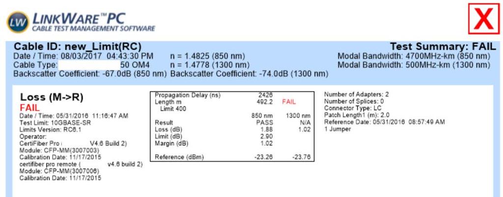
55 Como?!?


56 2Km = Pasa TIA y Limit de IEEE 10GBASE-SR= 400 Cabling Standards: TIA 568 ISO X Application Standards: 10GBaseS 40GBase-SR Fluke Corporation. All rights reserved.
57 TIER 2 TESTING Tier II testing is Tier I plus the use of an OTDR Ideal for Troubleshooting

58 Accurate OTDR Testing for HighSpeed Links Launch Fiber Tail Fiber Will give loss of the first connector Will give loss of the last connector 2015 Fluke Corporation. All rights reserved. 58
59 OTDR testing for High Speed Links Must use launch and receive fibers Need to run the test Bi-Directionally Need to measure reflectance 2015 Fluke Corporation. All rights reserved.
60 Bad No Tail/Receive fiber what is loss at far connector?
61 Bad No Tail/Receive fiber what is loss at far connector?
62 Good Measurement Launch and Tail/Receive Fiber used so both connectors can be measured
63 Good Measurement Launch and Tail/Receive Fiber used so both connectors can be measured
64 By the Way, the 2 nd Connector is Bad Notice the Poor Reflectance Value

65 What is reflectance? An air gap between the end faces of a fiber also cause Fresnel reflections to occur Fluke Corporation. All rights reserved.


66 Reflectance is Caused by Poor Termination and Dirty Connectors
67 Reflected Signal Arriving Outside of Bit Period Fiber with poor reflectance 10 Gb/s Bit Period FCS/CRC Error Fiber with Good Reflectance 10 Gb/s Bit Period 2015 Fluke Corporation. All rights reserved. Slide courtesy of OFS

68 Reflected Signal Arriving Outside of Bit Period Fiber with poor reflectance 10 Gb/s Bit Period Fiber with Good Reflectance 10 Gb/s Bit Period 2015 Fluke Corporation. All rights reserved. Slid e cou

69 Reflected Signal Arriving Outside of Bit Period Fiber with poor reflectance 10 Gb/s Bit Period Fiber with Good Reflectance 10 Gb/s Bit Period 2015 Fluke Corporation. All rights reserved. Slid e cou

70 Exemplo de una Fantasma
 -35 db for multimode -40 db for singlemode -55 db for APC singlemode No reflectance limit Reflectance limit -35 db Same")
71 Specify a Reflectance Limit for OTDR testing OTDR loss event measurements heavily rely on good reflectance Poor reflectance can result in Optimistic / negative loss readings Errors when the application runs Agree on a reflectance limit As a guide (talk to your vendor) -35 db for multimode -40 db for singlemode -55 db for APC singlemode No reflectance limit Reflectance limit -35 db Same link tested 2015 Fluke Corporation. All rights reserved.
72 Vamos ver otro ejemplo?

73 Tenemos Resultados Bi-Direcionales Esto esta bien!
74 Pocos eventos, nada inesperado
75 Perdidas Menores a 0.75 db

76 Y la Reflectancia? Esta Bien
77 In Conclusion Looking forward to 25G per λ Know your current requirements At least 10G? Future applications will have tighter loss and length budgets Measure accurately Tier I use correct budget values REF vs STD Tier 2 Measure reflectance in addition to loss 2015 Fluke Corporation. All rights reserved.

78 Thank you, Gracias, Obrigado Jim Davis Fluke Networks 6920 Seaway Blvd Everett, WA 98271
One Enterprise. One Infrastructure. One Partner. Optical Fiber Loss Testing. Optical loss testing in the field is not as simple as it seems.
 Optical loss testing in the field is not as simple as it seems. Abstract Optical Fiber Loss Testing Optical loss testing of multimode fiber can be affected by many variables, including fiber mismatch,
Field Testing Update
 Field Testing Update Adrian Young Fluke Networks November, 2013 Singapore Objectives for this session Copper field standards update Look at new copper field measurements Fiber field standards update IEC
40GBASE-SR4 & URM-Infrastructure. Verification with BER-T and OTDR. White Paper
 40GBASE-SR4 & URM-Infrastructure Verification with BER-T and OTDR White Paper WHITE PAPER 3 Table of contents Table of contents... 3 Executive Summary... 4 URM-System... 5 Technical Background... 7 Verification...
How Bend Insensitive Multimode Fiber is Affecting Installation and Testing of Enterprise and Data Center Cabling
 How Bend Insensitive Multimode Fiber is Affecting Installation and Testing of Enterprise and Data Center Cabling David Mazzarese, Technical Manager, Fiber Systems and Standards Engineering, OFS Learning
OPTICAL TECHNOLOGY TRAINING
 OPTICAL TECHNOLOGY TRAINING Richard Ednay www.ott.co.uk @RichardEdnay WBMMF & SWDM 1 What Whywill do we it do need for How When did they should I me? a What new type is SWDM of develop start it & using
HIGH BIT RATE OPTICAL FIBRE NETWORKS - optical fibre selection and implementation
 HIGH BIT RATE OPTICAL FIBRE NETWORKS - optical fibre selection and implementation prepared and delivered by ϕ 19th January 2000 PO Box MT65 LEEDS LS17 8YD UK Tel: +44 (0) 113 232 3721 Fax: +44 (0) 113
FIBER OPTIC CABLE ASSEMBLIES
 FIBER OPTIC CABLE ASSEMBLIES QUALITY CONNECTIONS START HERE Improve the quality of your connections with America Ilsintech s line of SM & MM SC, ST, LC and MPO/MTP cable assemblies. America Ilsintech manufactures
White Paper: The Ins and Outs of Testing Bend Insensitive Multimode Fiber (BIMMF): The Need for Encircled Flux
: The Need for Encircled Flux") White Paper: The Ins and Outs of Testing Bend Insensitive Multimode Fiber (BIMMF): The Need for Encircled Flux White Paper: The Ins and Outs of Testing Bend Insensitive Multimode Fiber (BIMMF): The Need
White Paper: The Ins and Outs of Testing Bend Insensitive Multimode Fiber (BIMMF): The Need for Encircled Flux White Paper: The Ins and Outs of Testing Bend Insensitive Multimode Fiber (BIMMF): The Need
400G-BD4.2 Multimode Fiber 8x50Gbps Technical Specifications
 400G-BD4.2 Multimode Fiber 8x50Gbps Technical Specifications As Defined by the 400G BiDi MSA Revision 1.0 September 1, 2018 Chair Mark Nowell, Cisco Co-Chair John Petrilla, FIT Editor - Randy Clark, FIT
Pluggable Transceiver Modules
 APPENDIXB Revised: April 2012 This appendix provides descriptions and specifications for the pluggable transceiver modules that are supported on the Catalyst 6 series Ethernet switching modules. The appendix
FIBER CABLE ASSEMBLIES Termini, Cable, and Connectors
 Features: Simplex and multichannel fiber optic cables: OM1, 2, 3, 4, SMF-28, POF Mil/Aero connectors: D38999, M28876, GPRB/EPXB, EN4165, Micro 38999, TFOCA, D-sub MIL/AERO termini: M29504/4, /5, /14, /15,
DELL EMC NETWORKING TRANSCEIVERS AND CABLES
 DELL EMC NETWORKING TRANSCEIVERS AND CABLES Features and benefits Hot-swappable for simplified maintenance (no -down required for installation or replacement) Some of the smallest and lowest 10GbE, 25GbE,
TEC NOTE #2 POLISHING TECHNIQUES FOR FIBER OPTIC CONNECTORS
 TEC NOTE #2 POLISHING TECHNIQUES FOR FIBER OPTIC CONNECTORS Critical to proper polishing is the applied process--the technique--that results in meeting the various specifications. This TEC NOTE discusses
There are lots of problems or challenges with fiber, Attenuation, Reflections, Dispersion and so on. So here we will look at these problems.
 The Hard theory The Hard Theory An introduction to fiber, should also include a section with some of the difficult theory. So if everything else in the book was very easily understood, then this section
TECHNICAL ARTICLE: DESIGN BRIEF FOR INDUSTRIAL FIBRE OPTICAL NETWORKS
 TECHNICAL ARTICLE: DESIGN BRIEF FOR INDUSTRIAL FIBRE OPTICAL NETWORKS Designing and implementing a fibre optical based communication network intended to replace or augment an existing communication network
GIGABIT ETHERNET. e-ready Building Next Generation IT infrastructures. The Cabling Partnership. Mike Gilmore Managing Director, e-ready Building
 Mike Gilmore Managing Director, Mike Gilmore Standards Activities Member: ISO/IEC JTC1 SC25 WG3: Generic Cabling ISO/IEC JTC1 SC25 Project Team: SOHO Convenor: ISO/IEC JTC1 SC25 WG3 IPTG: Industrial Premises
ASSEMBLY INSTRUCTIONS
 ASSEMBLY INSTRUCTIONS UTS LC Series BT 304 BT304 UTS LC Series Contents Tool & Material... 4 UTS LC Component details... 5 UTS LC Dimensions... 5 Assembly Instructions for UTS1JC18LCN & UTS6JC18LCN...
Data sheet OpDAT connection cable 2x1 OS2 - bend insensitive
 Illustrations Principle diagram Page 1/7 Product specification connection cable for direct connector termination with higher robustness cable structure: I-V(ZN)HH2, duplex patch cable with additional outer
CISCO DWDM GBICS. Figure 1. Cisco DWDM GBICs. Main features of the Cisco DWDM GBICs:
 DATA SHEET CISCO DWDM GBICS The Cisco Dense Wavelength-Division Multiplexing (DWDM) Gigabit Interface Converter (GBIC) pluggables allow enterprise companies and service providers to provide scalable and
Multimode Fiber Characterization Encircled Flux & Launch Condition Considerations
 Application Note Multimode Fiber Characterization Encircled Flux & Launch Condition Considerations Introduction Current communication data rates in local networks range from 10/100 Mbps for Ethernet to
GYM Bilgi Teknolojileri
 SFP Transceiver Module GLC SX MM GLC SX MM is 1000Base-SX SFP fiber optic transceiver for multimode fiber and it works at 850nm wavelength, Cisco GLC SX MM SFP is compatible with IEEE 802.3z and could
Multi-fiber testing for 40G Ethernet
 Multi-fiber testing for 40G Ethernet How do the standards look on the real job site? Aswin Babu Jagadeesan Software Engineer Softing Singapore Pte Ltd (Formerly Psiber Data Pte Ltd) Agenda Standards refresher
Advanced Fibre Testing: Paving the Way for High-Speed Networks. Trevor Nord Application Specialist JDSU (UK) Ltd
 Ltd") Advanced Fibre Testing: Paving the Way for High-Speed Networks Trevor Nord Application Specialist JDSU (UK) Ltd Fibre Review Singlemode Optical Fibre Elements of Loss Fibre Attenuation - Caused by scattering
Advanced Fibre Testing: Paving the Way for High-Speed Networks Trevor Nord Application Specialist JDSU (UK) Ltd Fibre Review Singlemode Optical Fibre Elements of Loss Fibre Attenuation - Caused by scattering
Comment Supporting materials: The Reuse of 10GbE SRS Test for SR4/10, 40G-LR4. Frank Chang Vitesse
 Comment Supporting materials: The Reuse of 10GbE SRS Test for SR4/10, 40G-LR4 Frank Chang Vitesse Review 10GbE 802.3ae testing standards 10GbE optical tests and specifications divided into Transmitter;
Transceiver, Chassis Connectors, and Cable and Adapter Specifications
 APPENDIXB Transceiver, Chassis Connectors, and Cable and Adapter Specifications Revised: January 4, 2012 This appendix covers the transceivers supported by the Catalyst 4948E and the Catalyst 4948E-F switches,
Improvements to Modal Noise Penalty Calculations
 Improvements to Modal Noise Penalty Calculations Petar Pepeljugoski, Daniel Kuchta and Aleksandar Risteski IBM T.J. Watson Research Center Yorktown Heights, NY 1598 Outline Modal Noise (MN) penalty calculation
WHITE PAPER LINK LOSS BUDGET ANALYSIS TAP APPLICATION NOTE LINK LOSS BUDGET ANALYSIS
 TAP APPLICATION NOTE LINK LOSS BUDGET ANALYSIS WHITE PAPER JULY 2017 1 Table of Contents Basic Information... 3 Link Loss Budget Analysis... 3 Singlemode vs. Multimode... 3 Dispersion vs. Attenuation...
Industrial Automation
 OPTICAL FIBER. SINGLEMODE OR MULTIMODE It is important to understand the differences between singlemode and multimode fiber optics before selecting one or the other at the start of a project. Its different
Multimode fiber media types for 802.3cd
 1 Multimode fiber media types for 802.3cd P802.3cd, Fort Worth, Texas September 12-16, 2016 Rick Pimpinella Jose Castro Brett Lane Panduit Labs, Panduit Corp. 2 Laser Optimized Multimode Fiber Types Fiber
Mixing TrueWave RS Fiber with Other Single-Mode Fiber Designs Within a Network
 Mixing TrueWave RS Fiber with Other Single-Mode Fiber Designs Within a Network INTRODUCTION A variety of single-mode fiber types can be found in today s installed networks. Standards bodies, such as the
User Manual. Installation Transmit Receive Module SFP/XFP
 User Manual Installation Dragon PTN Transmit Receive Module SFP/XFP Installation Transmit Receive Module SFP/XFP Technical support https://hirschmann-support.belden.com The naming of copyrighted trademarks
ORTRONICS FIBER TRUNK CABLE SYSTEM BY LEGRAND. designed to be better.
 ORTRONICS FIBER TRUNK CABLE SYSTEM BY LEGRAND designed to be better. a streamlined approach to network design THE ORTRONICS FIBER TRUNK CABLE SYSTEM BY LEGRAND TRUNK CABLES With current high bit rate transmission,
Data sheet OpDAT breakout cable 24x1 OM4 - bend insensitive
 Page 1/9 Illustrations Principle diagram See enlarged drawings at the end of document Product specification connection cable I-V(ZN)HH breakout cable for direct connector termination for indoors and outdoors
Migration to 50/125 µm in the Local Area Network
 Migration to 50/125 µm in the Local Area Network By Doug Coleman Introduction Enterprise local area networks (LAN) should be designed to support legacy applications as well as emerging high-data-rate applications.
Ox-RAC-08 Ribbon Angled Fiber Cleaver User Manual
 Ox-RAC-08 Ribbon Angled Fiber Cleaver User Manual Issue 2.0 Contents Introduction... 2 Contents of Cleaving Kit & Unpacking... 3 Cleaving Problems... 8 Blade damage:... 9 Cleaver Maintenance... 10 Cleaning
features and benefits
 features and benefits Fully waterblocked loose tube, gel-free design Medium-density polyethylene jacket Figure-8 cable design Available in 62.5 µm, 50 µm, single-mode and hybrid versions Simple access
Product Specification RoHS-6 Compliant 10Gb/s 850nm Multimode Datacom XFP Optical Transceiver
 Product Specification RoHS-6 Compliant 10Gb/s 850nm Multimode Datacom XFP Optical Transceiver PRODUCT FEATURES Hot-pluggable XFP footprint Supports 9.95Gb/s to 10.5Gb/s bit rates Power dissipation
- Characteristic impedance of cabling links is characterised by Return Loss
 ISO/IEC 11801 ISO 11801 is the principle design standard for structured cabling systems for all countries of the world that do not have more specific standards, such as ISO 11801 (European Union), TIA
MULTI-FIBER ENGINEERING EXCELLENCE
 17 MULTI-FIBER ENGINEERING EXCELLENCE MPO / MTP Fiber Cabling Solutions Special Fiber Termination Harsh Environment Fiber Cabling Solutions Cable Management & Fiber Components OPTEC TECHNOLOGY LIMITED
H3C Transceiver Modules User Guide
 H3C Transceiver Modules User Guide New H3C Technologies Co., Ltd. http://www.h3c.com Document version: 6W107-20180621 Copyright 2014-2018, New H3C Technologies Co., Ltd. and its licensors All rights reserved
CXP/CFP 100G MPO Cable Assembly
 Product updated on June 01, 2018 CXP/CFP 100G MPO Cable Assembly CXP/CFP 100G MPO/ cable assemblies are designed to make a connection between 2 CFP/CXP transceivers. They are built using 24 fiber ferrule
Testing of DWDM + CWDM high speed systems. Christian Till Technical Sales Engineer, EXFO
 Testing of DWDM + CWDM high speed systems Christian Till Technical Sales Engineer, EXFO Need more bandwidth? xwdm - Class of WDM Devices Wavelength Division Multiplexing (WDM) : Access 2 channels 1310nm,
Bending the Truth - Get the straight story about Corning ClearCurve multimode fibers
 Bending the Truth - Get the straight story about Corning ClearCurve multimode fibers WP6372 Issued: January 211 Introduction In 29, Corning introduced ClearCurve multimode fiber, the first standards compliant
AC : FIBER OPTICS COURSE FOR UNDERGRADUATE ELECTRICAL ENGINEERING STUDENTS
 AC 2009-385: FIBER OPTICS COURSE FOR UNDERGRADUATE ELECTRICAL ENGINEERING STUDENTS Lihong (Heidi) Jiao, Grand Valley State University American Society for Engineering Education, 2009 Page 14.630.1 Fiber
FIBER POLARITY: 40G and 100G OPTIONS
 FIBER POLARITY: 40G and 100G OPTIONS Why is this significant in the data center? Data centers will be one of the first places where we will see 40G and 100G transmission speeds. Large data centers being
SUPERSEDED. NOT the LATEST REVISION
 Figure 1 OPTIMATE 2.5mm bayonet ceramic connector kits listed in Figure 1 are designed to be applied to fiber optic cable. Coupling Receptacle Kit 501381 1 is used to mate two bayonet connectors in free
Outdoor, CCTV or CCTV, Fig 8 Armored.
 Outdoor, CCTV or CCTV, Fig 8 Armored. Outdoor stranded Fig 8 Armored, Fiber optic cable for aerial installation. It support application such as IEEE802.3, 10G Ethernet, Gigabit Ethernet, Fast Ethernet,
Network Challenges for Coherent Systems. Mike Harrop Technical Sales Engineering, EXFO
 Network Challenges for Coherent Systems Mike Harrop Technical Sales Engineering, EXFO Agenda 1. 100G Transmission Technology 2. Non Linear effects 3. RAMAN Amplification 1. Optimsing gain 2. Keeping It
Trends in Optical Transceivers:
 Trends in Optical Transceivers: Light sources for premises networks Peter Ronco Corning Optical Fiber Asst. Product Line Manager Premises Fibers January 24, 2006 Outline: Introduction: Transceivers and
Pluggable Transceivers
 DATA SHEET Pluggable Transceivers Industry-Standard Pluggable Transceivers and Direct Attach Cables BENEFITS BUSINESS ALIGNMENT Standards-based technology. Flexible interface options for 100Mbs, 1Gbps,10Gbps,
Ø560*336mm 4.25 kg 2100 ± 105m
 GUMT Mini-Breakout Cables (Distribution) Universal Indoor/ Outdoor A/I-VQ(ZN)H Standard Rodent Protection 05-0-0 v3.0 Ordering Information Belden Part Numbers Fibre Description / count 4 6 8 6 4 6.5/5-OM
LazrSPEED WideBand OM5 Solution Global Communication
 LazrSPEED WideBand OM5 Solution Global Communication To meet the challenges associated with escalating data rates and the ongoing need to build cost effective infrastructure that can support bandwidth
400G-FR4 Technical Specification
 400G-FR4 Technical Specification 100G Lambda MSA Group Rev 2.0 September 18, 2018 Chair Mark Nowell, Cisco Systems Co-Chair - Jeffery J. Maki, Juniper Networks Marketing Chair - Rang-Chen (Ryan) Yu Editor
Outdoor, Fig 8 Armored, Multi Tube
 Outdoor, Fig 8 Armored, Multi Tube Outdoor stranded Fig 8 Armored, Fiber optic cable for aerial installation. It support application such as IEEE802.3, 10G Ethernet, Gigabit Ethernet, Fast Ethernet, Ethernet,
Why Using Fiber for transmission
 Why Using Fiber for transmission Why Using Fiber for transmission Optical fibers are widely used in fiber-optic communications, where they permit transmission over long distances and at very high bandwidths.
Fixed Attenuators. Features and Benefits. Standards
 Features and Benefits Standard Fixed Attenuation Values of db up to 30 db Precision Polishing for Reduced Back Reflection Available in a Variety of Connector Types Polarization Insensitive Standards RoHS
OpDAT Universalkabel 1x4 OM4 - biegeunempfindlich, Klasse. Principle diagram
 Page 1/9 Illustrations Principle diagram See enlarged drawings at the end of document Product specification installation cable U-DQ(ZN)BH universal fiber optic cable for indoors/outdoors with central or
OxFAC-08 Angled Fiber Cleaver. User Manual. Issue 1.5
 OxFAC-08 Angled Fiber Cleaver User Manual Issue 1.5 Contents Issue & Scope... 2 Introduction... 2 Contents of Cleaving Kit & Unpacking... 3 Cleaving Problems... 8 Blade damage:... 9 Cleaver Maintenance...
SECTION 1 TABLE OF CONTENTS
 Contents Introduction A Complete Interconnect Solution... 1-2 Markets and Applications... 1-3 International Standard Documents Compliance... 1-3 Features and Benefits... 1-4 Characteristics and Performance
Electrical Concepts For Interconnect Professionals
 Electrical Concepts For Interconnect Professionals Overview What are common protocols What questions should you ask What are Glenair s solutions Proliferation of High Speed Electrical Systems in Mil\Aero
LX8501CDR 100G 100m QSFP28 Transceiver 100GBASE-SR4
 Product Features Compliant with IEEE Std 802.3bm,100G BASE SR4 Ethernet Compliant with QSFP28 MSA Management interface specifications per SFF-8636 Single MPO connector receptacle 4 channels 850nm VCSEL
Table of Contents. Cable Assemblies & Backplane Interconnects. Fiber Optic Products Catalog. Cable Assemblies &
 Table of Contents Cable Assemblies NEW Active Optical Cable Assemblies....................... 100, 101 LC Cable Assemblies....................................... 10-104 SECURE Cable Assemblies...................................
100G CWDM4 MSA Technical Specifications 2km Optical Specifications
 100G CWDM4 MSA Technical Specifications 2km Specifications Participants Editor David Lewis, LUMENTUM Comment Resolution Administrator Chris Cole, Finisar The following companies were members of the CWDM4
OptoLup TM POF cable Data Sheet. Overview. COMOSS OptoLup TM Cable is a type of APF, All. for the transmitting. compliant POF cables.
 IEEE 1394b Series Dongle OptoLup TM OptoLup TM Data Sheet Ver. 1.0 Overview COMOSS OptoLup TM Cable is a type of APF, All Plastic-fiber; both the core and the cladding are made of plastic, among of which
Parallel Fiber Application Note Introduction to types and uses of parallel multi-mode ribbon cable in optical fiber data transmission.
 Introduction to types and uses of parallel multi-mode ribbon cable in optical fiber data transmission. Document No: LA-970-069-00 Revision: 1.0 Rev. Date: April 15, 2010 Reflex Photonics Inc, 550 Sherbrooke
af-phy July 1996
 155.52 Mbps Short Wavelength Physical Layer Specification af-phy-0062.000 Technical Committee 155.52 Mbps Physical Layer Interface Specification for Short Wavelength Laser af-phy-0062.000 July 1996 1 ATM
10GBASE-S Technical Feasibility
 10GBASE-S Technical Feasibility Picolight Cielo IEEE P802.3ae Los Angeles, October 2001 Interim meeting 1 10GBASE-S Feasibility Supporters Petar Pepeljugoski, IBM Tom Lindsay, Stratos Lightwave Bob Grow,
GUXW. Mini-Breakout Cables (Distribution) Universal Indoor/ Outdoor, Steel Wire Armor (SWA) A/I-VQ(ZN)HBH Full Rodent Protection v5.
 Universal Indoor/ Outdoor, Steel Wire Armor (SWA) A/I-VQ(ZN)HBH Full Rodent Protection v5.") GUXW Mini-Breakout Cables (Distribution) Universal Indoor/ Outdoor, Steel Wire Armor (SWA) A/I-VQ(ZN)HBH Full Rodent Protection 05--0 v5.0 Ordering Information Belden Part Numbers Fibre Description / count
GUXW Mini-Breakout Cables (Distribution) Universal Indoor/ Outdoor, Steel Wire Armor (SWA) A/I-VQ(ZN)HBH Full Rodent Protection 05--0 v5.0 Ordering Information Belden Part Numbers Fibre Description / count
Pro. SimpliFiber. Getting Started Guide. Optical Power Meter and Fiber Test Kits
 SimpliFiber Pro Optical Power Meter and Fiber Test Kits Getting Started Guide PN 3314816 September 2008, Rev. 2 6/12 2008, 2010, 2012 Fluke Corporation. Printed in USA. All product names are trademarks
Development of Cleanliness Specification for Single- Mode Connectors with 1.25 and 2.5 mm Ferrules
 Development of Cleanliness Specification for Single- Mode Connectors with 1.25 and 2.5 mm Ferrules Dr. Tatiana Berdinskikh, Dr. Sun-Yuan Huang, Douglas H. Wilson OFC 26 March 6, 26 Authors Dr. Tatiana
Fieldworthy ROFL/OFL Multimode Fiber Differential Mode Delay Measurement System
 Fieldworthy ROFL/OFL Multimode Fiber Differential Mode Delay Measurement System Lew Aronson and Lisa Buckman HP Labs Palo Alto February 2, 1998 Outline Measurement Goals and Issues Functional Block Diagram
Product Specification. RoHS-6 Compliant 10Gb/s 850nm Multimode Datacom XFP Optical Transceiver FTLX8511D3
 Product Specification RoHS-6 Compliant 10Gb/s 850nm Multimode Datacom XFP Optical Transceiver FTLX8511D3 PRODUCT FEATURES Hot-pluggable XFP footprint Supports 9.95Gb/s to 10.5Gb/s bit rates Power dissipation
QSFP+ / QSFP28 application guide 2017/20/04
 QSFP+ / QSFP28 application guide 2017/20/04 40G QSFP+ QSFP+ to QSFP+ connectivity QSFP+ to 4x10G SFP+ aggregation SFP+ SFP+ SFP+ QSFP+ QSFP+ QSFP+ SFP+ Four technologies Direct Attached Cable Active Optical
Computer Networks
 15-441 Computer Networks Physical Layer Professor Hui Zhang hzhang@cs.cmu.edu 1 Communication & Physical Medium There were communications before computers There were communication networks before computer
Outside Plant All Dielectric
 Berk-Tek s Outside Plant Loose Tube ber optic cables are designed for installation in harsh enviroments such as direct burial, aerial lashing, conduit and pathways that are subjected to wide temperature
Fiber Optic Principles. Oct-09 1
 Fiber Optic Principles Oct-09 1 Fiber Optic Basics Optical fiber Active components Attenuation Power budget Bandwidth Oct-09 2 Reference www.flukenetworks.com/fiber Handbook Fiber Optic Technologies (Vivec
UniCam Connector Critical Steps
 UniCam Connector Critical Steps The UniCam connector has a fiber stub that is prepolished in the factory (Figure 1). To terminate, the field fiber must be stripped and cleaved, and must butt up against
FOT-930. Multifunction loss tester. MaxTester
 Multifunction loss tester FOT-930 MaxTester NETWORK TESTING OpTIcal FasTesT TM : three-wavelength measurement of optical loss, ORL and fiber length in 10 seconds All-in-one portable test solution: up to
SYSTIMAX 360 ipatch Fiber Shelf with Faceplate Instructions
 860463082 Issue 5, June 2014 SYSTIMAX 360 ipatch Fiber Shelf with Faceplate Instructions General The SYSTIMAX 360 ipatch G2 fiber shelf with faceplate is a SYSTIMAX approved product. This distribution
400G CWDM8 10 km Optical Interface Technical Specifications Revision 1.0
 400G CWDM8 10 km Optical Interface Technical Specifications Revision 1.0 Contact: cwdm8-msa.org CWDM8 10 km Technical Specifications, Revision 1.0 1 Table of Contents 1. General...5 1.1. Scope...5 1.2.
PPM-350C. For detailed inquiry please contact our sale team at
 PON POWER METER PPM-350C NETWORK TESTING OPTICAL Unique workflow management, for faster PON deployments Simultaneous measurement of all PON signals*, anywhere on the network Innovative workflow management,
Arista 100G Transceivers and Cables: Q&A
 Arista 100G Transceivers and Cables: Q&A What 100G Transceivers and Cables are available from Arista? Arista supports a full range of copper cables and optical transceivers for 100GbE, compliant to the
NEW YORK CITY COLLEGE of TECHNOLOGY
 NEW YORK CITY COLLEGE of TECHNOLOGY THE CITY UNIVERSITY OF NEW YORK DEPARTMENT OF ELECTRICAL AND TELECOMMUNICATIONS ENGINEERING TECHNOLOGY Course : Prepared by: TCET 4102 Fiber-optic communications Module
10GBd SFP+ Short Wavelength (850nm) Transceiver
 Transceiver") Preliminary DATA SHEET CFORTH-SFP+-10G-SR 10GBd SFP+ Short Wavelength (850nm) Transceiver CFORTH-SFP+-10G-SR Overview CFORTH-SFP+-10G-SR SFP optical transceivers are based on 10G Ethernet IEEE 802.3ae
Preliminary DATA SHEET CFORTH-SFP+-10G-SR 10GBd SFP+ Short Wavelength (850nm) Transceiver CFORTH-SFP+-10G-SR Overview CFORTH-SFP+-10G-SR SFP optical transceivers are based on 10G Ethernet IEEE 802.3ae
Product Specification
 Product Specification Extended Temperature 10Gb/s 850nm SFP+ Datacom Transceiver FTLX8574D3BNL PRODUCT FEATURES Hot-pluggable SFP+ footprint Supports 9.95 to 10.5 Gb/s bit rates* Power dissipation < 1W
Total care for networks. Introduction to Dispersion
 Introduction to Dispersion Introduction to PMD Version1.0- June 01, 2000 Copyright GN Nettest 2000 Introduction To Dispersion Contents Definition of Dispersion Chromatic Dispersion Polarization Mode Dispersion
DIRECTIONAL FIBER OPTIC POWER MONITORS (TAPS/PHOTODIODES)
") DIRECTIONAL FIBER OPTIC POWER MONITORS (TAPS/PHOTODIODES) Patent numbers: Canada 2,494,133, USA 7095931, 7295731, China 1672073, and Europe 03766088.3, EP1527363 Features: Telcordia GR-468 qualified Available
DIRECTIONAL FIBER OPTIC POWER MONITORS (TAPS/PHOTODIODES) Patent numbers: Canada 2,494,133, USA 7095931, 7295731, China 1672073, and Europe 03766088.3, EP1527363 Features: Telcordia GR-468 qualified Available
Product Specification. RoHS-6 Compliant 10Gb/s 850nm Multimode Datacom SFP+ Transceiver FTLX8571D3BCL
 Product Specification RoHS-6 Compliant 10Gb/s 850nm Multimode Datacom SFP+ Transceiver FTLX8571D3BCL PRODUCT FEATURES Hot-pluggable SFP+ footprint Supports 9.95 to 10.5 Gb/s bit rates* Power dissipation
Pitch Reducing Optical Fiber Array Two-Dimensional (2D)
") PROFA Pitch Reducing Optical Fiber Array Two-Dimensional (2D) Pitch Reducing Optical Fiber Arrays (PROFAs) provide low loss coupling between standard optical fibers and photonic integrated circuits. Unlike
PROFA Pitch Reducing Optical Fiber Array Two-Dimensional (2D) Pitch Reducing Optical Fiber Arrays (PROFAs) provide low loss coupling between standard optical fibers and photonic integrated circuits. Unlike
Transceiver Compatibility and Interoperability
 Overview Transceiver Compatibility and Interoperability The Arista optical transceivers and cables product range offer maximum deployment flexibility and cost optimized network connectivity. The Arista
5 Mbit/s Repeater Carrierband to Single-mode Fiber Optic
 Installation and Testing 5 Mbit/s Repeater Carrierband to Single-mode Fiber Optic Models CBR-7AC CBR-7DC This manual describes the procedures for installing and testing the CBR-7 Fiber-Optic Repeaters.
XBR C. 8Gbs SFP+ Transceiver
 XBR-000153-C Brocade 8GBase-LR SFP+ SMF 1310nm, 10km Reach, LC XBR-000153-C 8Gbs SFP+ Transceiver Features Duplex LC connector Support hot-pluggable Metal with lower EMI Excellent ESD protection DFB Transmitter
AXGE Gbps Single-mode 1310nm, SFP Transceiver
 AXGE-1354 1.25Gbps Single-mode 1310nm, SFP Transceiver Product Overview Features The AXGE-1354 family of Small Form Factor Pluggable (SFP) transceiver module is specifically designed for the high performance
Standard Monotube SAFE
 Application Mainly used in outside plant to building transitions and inter-building installations Fiber Count Single Mode Fibers Outer Diameter [mm] Cable Weight [kg/km] Design Optical Fibers Gel-filled
Marek Hajduczenia, ZTE Corp.
 Marek Hajduczenia, ZTE Corp. marek.hajduczenia@zte.pt » Terminology» Channel model» 1G-EPON power budgets» 10G-EPON power budgets» GPON power budgets» XGPON power budgets» CCSA defined power budgets for
FCQ1064-APC 1064 nm 1x4 Narrowband Coupler. Mounted on
 1 X 4 SINGLE MODE FIBER OPTIC COUPLERS Wavelengths from 560 nm to 1550 nm Available 25:25:25:25 Split Ratio Terminated with 2.0 mm Narrow Key or Connectors Use for Splitting Signals FCQ1064-APC 1064 nm
Betz & Limbach Projektkabel GmbH, Ringstraße 43, Bretzfeld, Tel / , Fax -58
 , Ringstraße 43, 74626 Bretzfeld, , Ringstraße 43, 74626 Bretzfeld, , Ringstraße 43, 74626 Bretzfeld, SFMx -85/13-01x02 Multimode Dual Window Couplers/Splitters Description: Multimode Dual Window Couplers
100-Gbps QSFP28 SR4 Optical Transceiver Module PN: WST-QS28-SR4-C
 Data Sheet 100-Gbps QSFP28 SR4 Optical Transceiver Module PN: General Description WaveSplitter s 100G-SR4 optical transceiver module (100G-SR4 TRx) with Quad Small Form-Factor Pluggable 28 (QSFP28) form-factor
Lecture 5 Transmission. Physical and Datalink Layers: 3 Lectures
 Lecture 5 Transmission Peter Steenkiste School of Computer Science Department of Electrical and Computer Engineering Carnegie Mellon University 15-441 Networking, Spring 2004 http://www.cs.cmu.edu/~prs/15-441
CFORTH-QSFP28-100G-LR4 Specifications Rev. D00B. Product Features
 Preliminary DATA SHEET CFORTH-QSFP28-100G-LR4 100G QSFP28 LR4 Optical Transceiver CFORTH-QSFP28-100G-LR4 Overview CFORTH-QSFP28-100G-LR4 QSFP28 LR4 optical transceivers are based on 100G Ethernet IEEE