ASSEMBLY INSTRUCTIONS
|
|
|
- Justin Smith
- 6 years ago
- Views:
Transcription


1 ASSEMBLY INSTRUCTIONS UTS LC Series BT 304
2

3 BT304 UTS LC Series Contents Tool & Material... 4 UTS LC Component details... 5 UTS LC Dimensions... 5 Assembly Instructions for UTS1JC18LCN & UTS6JC18LCN... 6 A - Cable preparation... 6 B - Backshell screwing for UTS1JC18LCN... 9 C - Backshell screwing for UTS6JC18LCN Assembly Instructions for UTS718LCN Cleaning & Inspection Safety Considerations SOURIAU 3
4 UTS LC Series BT304 Tool & Material The following tools and materials are necessary for preparation, assembly, inspection, and maintenance of the connector and cable assembly. Follow the tool instruction for operation and safety guidelines. TOOLS - Cable jacket strip tool - Aramid Fiber Shears - Fiber Stripping Tool - 15 mm U wrench - 28 mm U wrench mm U wrench - Nipper (Oeticker Standard pincers with straight jaws ) - Heat gun (optional) MATERIAL - LC contact: the UTS LC connector range can adapt all kind of LC contact as defined per IEC Cable: the UTS LC connector range can adapt all type of standard cable from 3 to 6mm outer diameter. Above these diameter limits some adaptations are necessary - Suggested glue: LOCTITE 480 PRISM Instant Adhesive ASSEMBLY INSTRUCTIONS The assembly should be done in a dust free and dried environment, in accordance with fiber optics good practices. Make sure that all components are free from contamination. The assembly instruction is only a guideline and the assembly/manipulations are under the responsibility of the assembler. Any change of product or material is under the responsibility of the assembler. 4 SOURIAU 2013

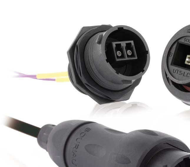
5 BT304 UTS LC Series UTS LC Component details UTS1JC18LCN, UTS6JC18LCN, UTS718LCN overview Receptacles Plug Backshell Ear Crimp support Gasket Tensile strength system Claw Nut DIMENSIONS (mm) Free Hanging Receptacle -UTS1JC18LCN 122 max Ø 42.5 max Ø 6 max Plug - UTS6JC18LCN 112 max Ø 42.5 max Ø 6 max Jam nut receptacle - UTS718LCN 18.5 max 17.5 max UTS618DCG2 for UTS6JC18LCN Sealing cap UTS18DCG2 for UTS1JC18LCN & UTS718LCN 34 max 24 max 5 max Ø 45.5 max Ø 32.5 max Ø 42.5 max 2013 SOURIAU 5

6 UTS LC Series BT304 Assembly Instructions for UTS1JC18LCN & UTS6JC18LCN A - Cable preparation 1. Slide the backshell onto the cable allowing 50 cm at the end of the cable for stripping the cable. Make sure to orient each component as shown in the UTS LC Component details section. 2. Using the cable jacket strip tool, strip the jacket to the dimension given in figure below, exposing the kevlar strength members and fiber. 3. Using the shears, trim the kevlar strength members to the length given in figure below. Fiber tube protection: 100±1 mm Kevlar: 40±1 mm 4. Fix the Kevlar using an adhesive tape on the individual fibers to facilitate the insertion of the crimp support. 5. Slide the crimp support (large diameter end first) over the fibers and the kevlar strength members until it bottoms on the cable outer jacket. 6. Separate the kevlar strength members in two groups. Use an adhesive tape to fix the kevlar strength members on the jacket. 6 SOURIAU 2013
. 8.")


7 BT304 UTS LC Series 7. Apply the instant adhesive on the fiber and cover the crimp support. (e.g. LOCTITE 480 PRISM). 8. Before the instant adhesive begins to harden,quickly slide the ear clamp over the fiber, orient the Clamp according the picture. Push the strength members back over the clamp until it bottoms on the rear flange of the support. 9. Crimp the both ear of the Clamp using the Nipper. Remove the kevlar strength members using using the shears. Check the good crimping by pulling manually. 11. Strip the fiber buffer according to your LC supplier recommendations and make sure to reach the final desired lengths for the individual fibers as described on the pictures below. Bare fiber Fiber buffer 2013 SOURIAU 7


8 UTS LC Series BT304 Assembly Instructions for UTS1JC18LCN & UTS6JC18LCN (suite) 12. Terminate the LC contact on the fiber according to your supplier instruction for gluing, cliving and polishing. Free hanging receptacle UTS1JC18LCN Free hanging receptacle UTS1JC18LCN: 94±0.2 mm Plug UTS6JC18LCN Plug UTS6JC18LCN: 84±0.2 mm 13. Fix the cable in a tool to avoid the rotation. 14. Plug the two LC: Make sure that each LC contact is in the right cavity A or B. You need to hear a CLICK. 8 SOURIAU 2013

9 BT304 UTS LC Series B - Backshell screwing for UTS1JC18LCN 1. Slide the blackshell and screw it using a 28 mm U-wrench. Tightened the backshell with a 4 Nm torque. 2. Control: Pull on the cable to ensure that the retention system bottoms in the backshell. 3. Screw the head nut using a 15 mm U-wrench. Tightened the head nut with a 2 Nm torque SOURIAU 9


10 UTS LC Series BT304 C - Backshell screwing for UTS6JC18LCN 1. You need a receptacle counter-part. Orient the polarization keys before you start mating the connectors. 2. Coupling plug with receptacle 3. Slide the blackshell and screw it using a 28 mm U-wrench. Tightened the backshell with a 4 Nm torque. 4. Control: Pull on the cable to ensure that the retention system bottoms in the backshell. 10 SOURIAU 2013


11 BT304 UTS LC Series 5. Screw the head nut using a 15 mm U-wrench. Tightened the head nut with a 2 Nm torque. Recommendation Use the caps, UTS618DCG2 for plug or UTS18DCG2 for receptacle to protect the LC contacts from surrouding contamination. You need to hear a CLICK SOURIAU 11


12 UTS LC Series BT304 Assembly Instructions for UTS718LCN 1. Strip the fiber buffer according to your LC supplier recommendations and make sure to reach the final desired lengths for the individual fibers as described on the pictures below. Bare fiber Fiber buffer 2. Terminate the LC contact on the fiber according to your supplier instruction for gluing, cliving and polishing. 3. Plug the two LC in the receptacle. Make sure that each LC contact is in the right cavity A or B. You need to hear a CLICK. 4. Seat o-ring, place receptacle in the panel cut-out. Optional coding ring Jam nut mm O-ring mm Panel thickness: 3.2mm max UTS718LCN 12 SOURIAU 2013


13 BT304 UTS LC Series 5. Tightened the jam nut with a torque of 5 Nm, using a 36.5 mm U- wrench. 6. Coupling SOURIAU 13

 to inspect the termini endface for contamination, chips, pits, scratches and shatters in the core and in the inner of the")

14 UTS LC Series BT304 Cleaning & Inspection Cleaning and visual inspection of a termini endface is part of the good practices for fiber optics. This is necessary to ensure the good optical performances of an LC contact inside a UTS LC connector. Please note that most of the standard inspection and cleaning tool on the market can be used for maintenance of an LC contact mounted in an UTS LC connector. 1 Inspection A- Use a fiber optic video probe (magnification X200 minimum) to inspect the termini endface for contamination, chips, pits, scratches and shatters in the core and in the inner of the cladding (see figure below). B- If dirt, debris or other surface contamination is identified then clean (see below). 2 Cleaning A- Use a lint free tip moistened with 99% reagent grade isopropyl alcohol or optical quality cleaning fluid to clean the termini endface. Always wipe in one direction, not back and forth. B- Dry the termini endface with a dry tip. C- Re-inspect the termini endface with a fiber optic video probe (Magnification x200 minimum) and verify that the contamination has been removed. D- If the contamination is still present then repeat step A & B. E- If after repeated attempts, the contamination is still present and cannot be removed like minor scratches, chips or pits then re-polish the optical contact (refer to the LC supplier instruction). E.g. Magnification X 400 of two multimode fibers For more details, please refer to the acceptance criteria and cleaning procedures defined by IEC for multimode or singlemode connector termini endface 14 SOURIAU 2013 Clean and good termini endface Contaminated or scratched termini endface
15 BT304 UTS LC Series Safety Considerations Safety glasses A- Safety glasses to protect your eyes from accidental injury are strongly recommended when handling chemicals and cutting fibers. Pieces of glass fiber are very sharp and can damage the cornea of the eye. B- Glue Glue may cause eye and skin irritation. Avoid contact with eyes, skin or clothing. Avoid prolonged or repeated breathing of vapor. Use with adequate ventilation. C- Fiber Precautions Cleaved glass fibers are very sharp and can pierce the skin easily. Do not let cut pieces of fiber stick to your clothing or drop in the work area where they can cause injury later. Use tweezers to pick up cut or broken pieces of the glass fibers and place them in a debris container. Keep your work area clean. D- Laser Precautions. Laser light is invisible and can damage your eyes. Never look into the end of a fiber which may have a laser coupled to the opposite end SOURIAU 15
16 INDUTSLCBT01 Copyright SOURIAU All information in this document presents only general particulars and shall not form part of any contract. All rights reserved to SOURIAU for changes without prior notification or public announcement. Any duplication is prohibited, unless approved in writing.
MIL-STD B (SH) UPDATE
 UPDATE") MIL-STD-2042-5B (SH) UPDATE Method 5A1 Insert Equipment and materials (to be added to table 5A1-I) Pliers 3.2.2.2 Cable and fiber preparation for Fiber Systems International backshells. Step 1: Ensure
MIL-STD-2042-5B (SH) UPDATE Method 5A1 Insert Equipment and materials (to be added to table 5A1-I) Pliers 3.2.2.2 Cable and fiber preparation for Fiber Systems International backshells. Step 1: Ensure
SUPERSEDED REVISION. Reasons for reissue of this instruction sheet are provided in Section 7, REVISION SUMMARY.
 PRO BEAM Jr. EB cable plug connectors are designed to be installed onto jacketed fiber optic cable with KEVLAR strength members. The connector must be assembled using a cable plug connector shell kit,
SUPERSEDED. NOT the LATEST REVISION
 Figure 1 OPTIMATE 2.5mm bayonet ceramic connector kits listed in Figure 1 are designed to be applied to fiber optic cable. Coupling Receptacle Kit 501381 1 is used to mate two bayonet connectors in free
3M No Polish SC/APC Angle Splice Connector Jacket for 2 x 3 mm FRP and 1.6 to 3.0 mm Cable 8802-T/APC/AS/1.6-3
 3M No Polish SC/APC Angle Splice Connector Jacket for 2 x 3 mm FRP and 1.6 to 3.0 mm Cable 8802-T/APC/AS/1.6-3 Instructions October 2013 3 1.0 Table of contents 1.0 Summary...3 2.0 Cable and Fiber Preparation...4
Termination Procedure
 Connector Piece Parts Contact/Connector Head Twist On Nut MX MX Boot Procedure Chart Procedure Tool Required Tool Part Number Cable Preparation & Fiber Cleaning Jacket Stripper 86710-0004 Cable Preparation
Termination for M29504/4, /5, /6 & /7, Style 2 (Tight)
") Ξ XiOptics Optical fiber termination is a very process dependent operation. Consideration of the optical terminus, adhesive system and the optical cable/fiber must all be taken into consideration. XiOptics,
Ξ XiOptics Optical fiber termination is a very process dependent operation. Consideration of the optical terminus, adhesive system and the optical cable/fiber must all be taken into consideration. XiOptics,
Reasons for reissue are in Section 6, REVISION SUMMARY.
 Figure 1 This instruction sheet covers the application of OPTIMATE FSMA Fiber Optic Connector Types 905 and 906 for data and telecommunications applications. Base part numbers which apply to each type
COMPONENT IDENTIFICATION
 SC OptiCam Fiber Optic Connectors Panduit Corp. 2017 INSTALLATION INSTRUCTIONS READ ALL INSTRUCTIONS COMPLETELY BEFORE PROCEEDING COMPONENT IDENTIFICATION CONNECTOR ASSEMBLY SIMPLEX Dust Cap Outer Housing
COMPONENT IDENTIFICATION
 ST OptiCam Fiber Optic Connectors Panduit Corp. 2017 INSTALLATION INSTRUCTIONS READ ALL INSTRUCTIONS COMPLETELY BEFORE PROCEEDING COMPONENT IDENTIFICATION CONNECTOR ASSEMBLY Jacketed Boots Available Separately
COMPONENT IDENTIFICATION
 SC OPTI-CRIMP Multimode Fiber Optic Connector Part Numbers: FSCMM**, FSCMM2.0**, FSCMM50**, FSCMM502.0**, FSCDMM, FSCDMM50 Panduit Corp. 2006 CONNECTOR ASSEMBLY INSTALLATION INSTRUCTIONS READ ALL INSTRUCTIONS
UniCam Connector Critical Steps
 UniCam Connector Critical Steps The UniCam connector has a fiber stub that is prepolished in the factory (Figure 1). To terminate, the field fiber must be stripped and cleaved, and must butt up against
Applications Engineering Notes
 Applications Engineering Notes Document Title Document Number Operating Instructions for the US Conec AEN-1408 Revision Number 1.0 Effective Date December 15, 2011 THE USE OF SAFETY GLASSES FOR EYE PROTECTION
Applications Engineering Notes
 Applications Engineering Notes Document Title Document Number 24 Fiber MTP Brand Connector Installation Onto Multimode or Single-mode 3.0 mm and 3.6 mm Jacketed Round Cable With Stranded or Bundled Loose
Technical Information
 UTO Series Technical Information Tooling... 2 Crimping Instructions... 3 Handle & Interchangeable Heads... 5 Extraction Tools... 6 Assembly Instructions... 7 1 Tooling Standard contacts Contact size #12
GORE Aerospace Ethernet Cables
 Termination Instructions The following procedures are based on Gore s best practices for terminating GORE Aerospace with the Amphenol Oval Contact System (OCS) for both plug and receptacle versions. These
Instructions for Preparing OPTICAL GROUND WIRE IN AN ISOLATOR
 Instructions for Preparing OPTICAL GROUND WIRE IN AN ISOLATOR NOTE: EXCEPT AS MAY BE OTHERWISE PROVIDED BY CONTRACT, THESE DRAWINGS AND/OR SPECIFICATIONS ARE THE PROPERTY OF AFL, ARE ISSUED IN STRICT CONFIDENCE
SC One Piece Connectors Termination Procedure Series: 728-NNN0-NNN0N
 SC One Piece Connectors Termination Procedure Series: 728-NNN0-NNN0N C B A Version Update address and fax number Revise Format Initial Release Revision History Summary 10/26/18 12/1/03 1997 Issue Date
DEPARTMENT OF DEFENSE STANDARD PRACTICE FIBER OPTIC CABLE TOPOLOGY INSTALLATION STANDARD METHODS FOR NAVAL SHIPS (CONNECTORS AND INTERCONNECTIONS)
") METRIC 29 September 1997 SUPERSEDING MIL-STD-2042-5(SH) 7 July 1993 DEPARTMENT OF DEFENSE STANDARD PRACTICE FIBER OPTIC CABLE TOPOLOGY INSTALLATION STANDARD METHODS FOR NAVAL SHIPS (CONNECTORS AND INTERCONNECTIONS)
METRIC 29 September 1997 SUPERSEDING MIL-STD-2042-5(SH) 7 July 1993 DEPARTMENT OF DEFENSE STANDARD PRACTICE FIBER OPTIC CABLE TOPOLOGY INSTALLATION STANDARD METHODS FOR NAVAL SHIPS (CONNECTORS AND INTERCONNECTIONS)
600G2 Internal Sliding Adapter Panel Shelf Instructions
 Instruction Sheet 860391986 Issue 6, February 2013 SYSTIMAX Solutions 600G2 Internal Sliding Adapter Panel Shelf Instructions General The SYSTIMAX 600G2 adapter panel shelf is 19-inch wide x 1.75-inch
Loose Tube Cable End Preparation for Splicing For Series 11D, 1GD, 12D, 1AD, 1DD, 1CD, 11, 1G, 12, 12L, 1A, 1D, 1C, 1NY, 13, 1H, HZD and HZA
 Loose Tube Cable End Preparation for Splicing For Series 11D, 1GD, 12D, 1AD, 1DD, 1CD, 11, 1G, 12, 12L, 1A, 1D, 1C, 1NY, 13, 1H, HZD and HZA NOTE: These installation instructions have been written for
SYSTIMAX 360 ipatch Fiber Shelf with Faceplate Instructions
 860463082 Issue 5, June 2014 SYSTIMAX 360 ipatch Fiber Shelf with Faceplate Instructions General The SYSTIMAX 360 ipatch G2 fiber shelf with faceplate is a SYSTIMAX approved product. This distribution
SC & FC/PC3 Pull-Proof Fiber Optic Connectors
 SC & FC/PC3 Pull-Proof Fiber Optic Connectors Instructions Termination Procedures for Multimode Field-Mountable Connectors using Hot Melt Adhesive Issue 1, May 1993 Contents: A) Warnings, Recommendations
Miniature Waterproof Shielded Connectors
 Miniature Waterproof Shielded Connectors LF Series Mated dimensions 8.9 mm max. ( pos.). Ø Receptacle Plug Short turn bayonet lock Features. Ease of shielded termination and connector assembly All components
DEPARTMENT OF DEFENSE STANDARD PRACTICE
 DEPARTMENT OF DEFENSE STANDARD PRACTICE METRIC MIL-STD-2042-5C(SH) 18 October 2016 SUPERSEDING MIL-STD-2042-5B(SH) 25 July 2002 FIBER OPTIC CABLE TOPOLOGY INSTALLATION STANDARD METHODS FOR SURFACE SHIPS
SYSTIMAX 360 ipatch G2 Fiber Shelf with Faceplate Instructions
 Instruction Sheet 860463082 Issue 4, February 2013 SYSTIMAX Solutions SYSTIMAX 360 ipatch G2 Fiber Shelf with Faceplate Instructions General The SYSTIMAX 360 ipatch G2 fiber shelf with faceplate is a SYSTIMAX
GORE Aerospace Ethernet Cables
 Termination Instructions The following procedures are based on Gore s best practices for terminating GORE Aerospace with the Carlisle Octax Connector System for both socket and plug versions. These procedures
Issue 2 JUly Fitel USA Corp Page 1 of 16 All Rights Reserved Printed in U.S.A.
 OFS EZ Installation for SC 640-252-049-02-UNIV Instruction Sheet Fiber Optic Connectors Comcode D05AK0032 (Multimode and Singlemode) Using Universal Polishing Procedure Table of Contents 1. General...2
AMPSEAL* Automotive Plug Connector and Header Assembly
 AMPSEAL* Automotive Plug Connector and Header Assembly Application Specification 114-16016 17 APR 14 NOTE NOTE i All numerical values are in metric units [with U.S. customary units in brackets]. Unless
Cannon Trident Connectors
 Power Contacts APK Power Contacts Socket Pin 30 A current rating. For use with Neptune connectors. Part Number Wire Range Wire Loose (100) Reeled (3000) Insulation Strip mm 2 Size Contact Description*
Miniature Waterproof Shielded Connectors
 All non-rohs products have been discontinued, or will be discontinued soon. Please check the products status on the Hirose website RoHS search at www.hirose-connectors.com, or contact your Hirose sales
UTL Field Installation 5 pos
 UTL Series 145 UTL Field Installation 5 pos Make your field installation Quick & Reliable. Time Saving Long Life Expectancy Reliable Installation Cost Saving UTL field installation has been designed to
High Speed Air Turbine Handpiece
 OPERATION MANUAL High Speed Air Turbine Handpiece Please read this Operation Manual carefully before use and file for future reference. Handpiece should not be used with friction grip burs exceeding 18.5
Crimping Dies for TERMINYL* and PLASTI-GRIP* Terminals and Splices
 Crimping Dies for TERMINYL* and PLASTI-GRIP* Terminals and Splices Instruction Sheet 408-10051 11 APR 17 Rev D PROPER USE GUIDELINES Cumulative Trauma Disorders can result from the prolonged use of manually
FIBRE OPTIC CONNECTOR TERMINATION HOOK UP PROCEDURE
 Fibre FIBRE OPTIC CONNECTOR TERMINATION HOOK UP PROCEDURE (AI502 Rev C 29Jun17) Images are for illustration purposes only. Product supplied may differ slightly from that shown. Hawke International UK Office,
Rev B C-RING TOOL VA0375 ½ in. OPERATING MANUAL
 Rev B 4-30-0 C-RING TOOL VA0375 ½ in. OPERATING MANUAL Operational Instructions for Vertex C-Ring Tool VA0375 Vertex Fasteners is committed to providing our customers with world-class customer service
DISTRIBUTION STATEMENT A. Approved for public release; distribution is unlimited.
 METRIC 25 July 2002 SUPERSEDING MIL-STD-2042-5A(SH) 29 September 1997 MIL-STD-2042-5(SH) 7 July 1993 DEPARTMENT OF DEFENSE STANDARD PRACTICE FIBER OPTIC CABLE TOPOLOGY INSTALLATION STANDARD METHODS FOR
SCULL HANDLES AND GRIPS INSTRUCTION BOOKLET
 SCULL HANDLES AND GRIPS INSTRUCTION BOOKLET Contents Section I: Scull Grip Replacement: Fixed Handle or 10 cm Length Adjustment System Refer to this section if you need to replace the grips on your fixed
Powersafe Termination Guide
 Powersafe Termination Guide Contents Index 1. Introduction 2. Overview 3. Termination Methods 3.1 Set screw termination 3.2. Recommended Assembly Procedure for Panel Mounted Connectors 3.3. Crimp Termination
Door window. Front door window, assembly overview
 64-50 Door window Front door window, assembly overview 1 - Window channel Pushed onto flange 2 - Door window Removing Page 64-52 Adjusting Page 64-53 3 - Door 4 - Outer window channel Pushed onto flange
Miniature Waterproof Shielded Connectors
 Miniature Waterproof Shielded Connectors LF Series Mated dimensions (Example : LF07) 8.9 mm max. ( pos.). Oct..07 Copyright 07 HIROSE ELECTRIC CO., LTD. All Rights Reserved. Features. Ease of shielded
Ox-RAC-08 Ribbon Angled Fiber Cleaver User Manual
 Ox-RAC-08 Ribbon Angled Fiber Cleaver User Manual Issue 2.0 Contents Introduction... 2 Contents of Cleaving Kit & Unpacking... 3 Cleaving Problems... 8 Blade damage:... 9 Cleaver Maintenance... 10 Cleaning
Installation Instructions
 Rev C, April 2018 Installation Instructions STANDARD DENSITY (SD) Shelf Sliding and Fixed Versions General The COMMSCOPE SD 1U and 2U fiber optic combination shelves come equipped with a modular faceplate.
Celerity Fiber Termination Kit
 Celerity Fiber Termination Kit User Guide Product Overview The Celerity Fiber Termination Kit (CT-FTK) is a professional tool set for splicing and terminating fiber optic cables in the field or at an assembly
AMPHENOL CORPORATION Amphenol Industrial. Termination Instructions: L-1295 SAE AS50151, AC, ACA and GT Series Solder and Crimp
 AC and SAE AS50151 AMPHENOL CORPORATION Industrial ACAB and GT Series Threaded Standard Cylindrical Connectors AMPHENOL CORPORATION Industrial Phone: 8883649011 191 Delaware Avenue Sidney, NY 138381395
TOYOTA TUNDRA 2015 BLACK TEXTURED FENDER FLARE
 TOYOTA TUNDRA 2015 BLACK TEXTURED FENDER FLARE Part Number: 00016-34083-02 Accessory Code: BF1000 Conflicts Note: Kit Contents Item # Quantity Reqd. Description 1 1 Left Front Fender Flare 2 1 Right Front
PRODUCT: LOKI INSTALLATION INSTRUCTIONS. Product is covered by U.S. patents. For more information visit
 R INSTALLATION INSTRUCTIONS PRODUCT: LOKI CONFIGURATION: SINGLE DOOR MOUNT: GLASS MOUNT Product is covered by U.S. patents. For more information visit www.krownlab.com . TOOLS + MATERIALS REQUIRED TOOLS
STANDARD INSTALLATION PROCEDURES FOR RAYATEN COATED MOULDED PARTS STRAIGHT, 90 AND 45
 Rayaten Moulded Parts Installation Procedures Code of Practice ELE-3COP-505 15 th Feb 2018 Class I STANDARD INSTALLATION PROCEDURES FOR RAYATEN COATED MOULDED PARTS STRAIGHT, 90 AND 45 ELE-3COP-505 TE
Miniature Waterproof Shielded Connectors
 Miniature Waterproof Shielded Connectors LF Series Mated dimensions (Example : LF07) 8.9 mm max. ( pos.). Sep..08 Copyright 08 HIROSE ELECTRIC CO., LTD. All Rights Reserved. Features. Ease of shielded
4.2 - PUMP MAINTENANCE MODELS: AC, AS, WC, WS
 4.2 - PUMP MAINTENANCE MODELS: AC, AS, WC, WS 4.2.1 - EXPLODED VIEW DRAWING REF NO. 1 2 4 QTY 3 1 1.5 5 ¾ HP HP HP HP HP DESCRIPTION PART # 1 CASE 1.25 x 1 NPT 018266 1 CASE 1.25 X 1 NPT 018268 1 CASE
PRO- CRIMPER* III Hand Crimping
 PRO- CRIMPER* III Hand Crimping Instruction Sheet Tool Assembly 58448-2 408-9357 With Die Assembly 58448-3 10 Mar 11 PROPER USE GUIDELINES Cumulative Trauma Disorders can result from the prolonged use
Side and rear window, assembly overview
 64-7 Side and rear window, assembly overview 1 - Side/rear window Removing Unbroken Page 64-9 Broken Page 64-11 Installing Page 64-13 Curing time Page 64-21 Re-sealing Page 64-25 2 - PUR adhesive sealant
Elcometer Muller Laboratory Grinder
 English Elcometer 2000 Muller Laboratory Grinder Operating Instructions English is a registered trademark of Elcometer Limited. All other trademarks acknowledged. Copyright Elcometer Limited. 2009. All
CEELOK FAS-T* High-Speed Circular Connector System
 CEELOK FAS-T* High-Speed Circular Connector System Application Specification 114-32025 02 APR 12 NOTE i All numerical values are in metric units [with U.S. customary units in brackets]. Dimensions are
JUL 15 Rev E
 ORIGINAL INSTRUCTIONS SDE PEW-12 Hand Crimping Tool Assembly 2031734-1 with Die Assembly 2031734-2 Instruction Sheet 408-10243 02 JUL 15 Rev E PROPER USE GUIDELINES Cumulative Trauma Disorders can result
Curium 19H Installation Instructions & Parts List
 Curium 19H Installation Instructions & Parts List Illustration Curium 19H Right Hand Page 1 of 15 01/07/2016 Revision 2.1 IMPORTANT This shower screen / enclosure must be installed by suitably qualified
PRODUCT SERVICE MANUAL FOR CIG Mechanical Seal Triple Pumps
 PRODUCT SERVICE MANUAL FOR CIG Mechanical Seal Triple Pumps WARNING The Imo General Installation Operation, Maintenance, and Troubleshooting Manual, (No. SRM00046), as well as all other component manuals
8-Ton Manual Splitter OWNER S MANUAL
 8-Ton Manual Splitter OWNER S MANUAL WARNING: Read carefully and understand all ASSEMBLY AND OPERATION INSTRUCTIONS before operating. Failure to follow the safety rules and other basic safety precautions
TRUE TECHNICAL SERVICE MANUAL - ALL MODELS. DOORS/DRAWERS/LIDS
 DOORS/DRAWERS/LIDS 55 56 NOTES DOORS/DRAWERS/LIDS Swing s 73 74 NOTES INSTALLATION OF A GDM-SWING DOOR Phillips Head Screwdriver (2) - 1/8" Drift Punches (forged) Top Bracket NOTE: It may be necessary
OxFAC-08 Angled Fiber Cleaver. User Manual. Issue 1.5
 OxFAC-08 Angled Fiber Cleaver User Manual Issue 1.5 Contents Issue & Scope... 2 Introduction... 2 Contents of Cleaving Kit & Unpacking... 3 Cleaving Problems... 8 Blade damage:... 9 Cleaver Maintenance...
1. TOOLS + MATERIALS REQUIRED
 R INSTALLATION INSTRUCTIONS PRODUCT: BALDUR + ODEN CONFIGURATION: BI-PARTING DOOR MOUNT: TOP MOUNT Product is covered by U.S. patents. For more information visit www.krownlab.com. TOOLS + MATERIALS REQUIRED
SAFETY THIS PRODUCT IS FOR OFFROAD USE ONLY. ALL LIABILITY FOR INSTALLATION AND USE RESTS WITH THE OWNER.
 SAFETY Your safety and the safety of others is very important. In order to help you make informed decisions about safety, we have provided installation instructions and other information. These instructions
1.0 Tool Components and Operation Instructions
 DBS-2100 MANUAL BANDING TOOL FOR ¼ STAMPED BUCKLE BANDS DATASHEET SEE PAGE 20 FOR IMPORTANT INFORMATION CONCERNING LIMITED WARRANTY AND LIMITATION OF LIABILITY. INTRODUCTION The Daniels DBS-2100 (M81306/1A)
Wall Mount Dust Collector 650 CFM Instructions
 Wall Mount Dust Collector 650 CFM Instructions Effective Febuary 2018 Review full instruction manual prior to use for important safety information. Always check Rockler.com to confirm that you are using
tile redi redi DOOR Redi Redi Swing Slide g TM TM...Opening Doors to Stunning Showers! TM TM SERIES: CONFIGURATION: MOUNTING PACKAGE:
 redi DOOR INSTALLATION INSTRUCTIONS tile redi Redi Redi Swing Slide g TM TM...Opening Doors to Stunning Showers! TM TM SERIES: CONFIGURATION: MOUNTING PACKAGE: 3000 Door-Door Header, sliding doors RDQCI5301
Clearview Railing System Installation Instructions
 Clearview Railing System Installation Instructions Disclaimer: AGS Stainless, Inc. has its Clearview Railing Systems designed by a professional engineer to meet the requirements of the latest national
Instruction manual SUN-PM100L. SUN-PM100L Polishing Machine English
 Instruction manual SUN-PM100L SUN-PM100L Polishing Machine English Table: SUN-UM-TL-PM001 Version: A/0 Fiber Optic Solutions Provider Ⅰ Safety Precautions To ensure safe operation and maximize product
3M Impact Protection Profile Installation System Instructions
 3M Impact Protection Profile Installation System Instructions IMPORTANT: READ INSTRUCTIONS FOR USE BEFORE OPERATING Intended Use: The 3M Impact Protection Profile Installation System is for installing
DRIVE COMPONENTS REMOVAL. 9. FXCW/C: see Figure Remove bolt (9), sprocket retainer (8), and thrust washer (7). NOTE PRIMARY DRIVE LOCKING TOOL
, sprocket retainer (8), and thrust washer (7). NOTE PRIMARY DRIVE LOCKING TOOL") DRIVE COMPONENTS REMOVAL PART NUMBER HD-7977 TOOL NAME PRIMARY DRIVE LOCKING TOOL S To remove the primary chain, remove compensating sprocket, clutch assembly and primary chain as an assembly:. Remove
DRIVE COMPONENTS REMOVAL PART NUMBER HD-7977 TOOL NAME PRIMARY DRIVE LOCKING TOOL S To remove the primary chain, remove compensating sprocket, clutch assembly and primary chain as an assembly:. Remove
Bushwacker Jeep Flat Style Fender Flares Front Pair
 Bushwacker Jeep Flat Style Fender Flares Front Pair Note: These instructions involve cutting parts of your vehicle. Please read all instructions prior to starting. Installation Time: 3-4 Hours Tools Required:
TECHNICAL GUIDELINE. DIN Connectors and N Connectors Installation Guidelines Using Manual Cable Prep Tools. Table of Contents
 DIN Connectors and N Connectors Installation Guidelines Using Manual Cable Prep Tools NOTE: These installation instructions have been written for qualified, experienced personnel. Please read them thoroughly
Fiber Splice Box (FSB-D) Installation Instructions
 Installation Instructions") Fiber Splice Box (FSB-D) Installation Instructions Table of Contents General Product Information... 1.0 Safety Precautions... 2.0 Tools Required... 3.0 Package Contents... 4.0 Installing the Product Unpacking...
Fiber Splice Box (FSB-D) Installation Instructions Table of Contents General Product Information... 1.0 Safety Precautions... 2.0 Tools Required... 3.0 Package Contents... 4.0 Installing the Product Unpacking...
Water Line and Water Line Assembly Gasket
 1 Preparation for Repair 1) Remove tip from scaler 2) Remove scaler from air supply 3) Remove gasket from back end of scaler. Examine gasket for obvious wear or disfigurement. Replace if necessary. 2 Remove
INSTRUCTIONS FOR AIRFLEX 36WCBEP/36WCSEP WEAR PLATE REPLACEMENT USING GASKET SEALING TAPE
 INSTRUCTIONS FOR AIRFLEX 36WCBEP/36WCSEP WEAR PLATE REPLACEMENT USING GASKET SEALING TAPE The material included in this kit is to be used for WC styles of brakes that are designed or upgraded to the EP
1/4 Rubber Spacer, 26 pcs. M5-.8 Machine Screw, 26 pcs 13. Female Wire Connector, 4 pcs
 97-06 Jeep Wrangler TJ Set Part #10920-07 Rev-3 12-15-08 A) B) C) D) E) F) G) STEP 1 - PRIOR TO INSTALLATION Bushwacker only approves installing the fl ares according to these written instructions with
C6 Corvette Rear Spoiler Kit CDC #
 2005 2008 C6 Corvette Rear Spoiler Kit CDC # 0542 7002 01 Note: Read installation instructions before starting Kit Includes: 1 C6 Rear Spoiler 2 CHMSL Bracket # 0542-3500-01 2 Screw 4.2 x 1.41 x 25 # 30005
Frameless Inline Door With Return QCI5263
 INSTALLATION INSTRUCTIONS Frameless Inline Door With Return QCI5263 WALL MOUNT HINGES FRAMELESS DOOR / PANEL / RETURN PANEL QCI5263 REV. 0 Page 1 Certified 06/17/2016 Parts List with wall mount hinges
Frameless Bypass Slider
 INSTALLATION INSTRUCTIONS Frameless Bypass Slider QCI-5301 3/8 or 1/4 Glass Bypass Slider with Exposed Rollers QCI5301 Rev 1 Page 1 Certified 6/5/2017 Tools: To install your New Shower Enclosure, you may
Curium 19.4H Installation Instructions & Parts List
 Curium 19.4H Installation Instructions & Parts List Illustration Curium 19.4H Right Hand Page 1 of 21 30/06/2016 Revision 1.0 IMPORTANT This shower screen / enclosure must be installed by suitably qualified
TNC SERIES General... 4 Interface... 5 Characteristics...6-7
 CONTENTS PAGE TNC SERIES General... 4 Interface... 5 Characteristics...6-7 TNC 50 Ω SERIES Plugs...8-9 Jacks...0- Jacks and receptacles... Receptacles...-4 Adapters... 5 Caps... 6 TNC 75 Ω SERIES Plugs...
SFP-550. Operating Manual MATSUHIDAI, MATSUDO-CITY, CHIBA JAPAN TEL: FAX:
 SFP-550 Operating Manual 296-1 MATSUHIDAI, MATSUDO-CITY, CHIBA 270-2214 JAPAN TEL: +81-47-388-6111 FAX: +81-47-388-4477 Safety Precautions To ensure safe operation and maximize product service life, observe
User Manual. Digital Compound Binocular LED Microscope. MicroscopeNet.com
 User Manual Digital Compound Binocular LED Microscope Model MD82ES10 MicroscopeNet.com Table of Contents i. Caution... 1 ii. Care and Maintenance... 2 1. Components Illustration... 3 2. Installation...
HIGH POWER COLLIMATORS AND FOCUSERS PIGTAIL STYLE
 Features HIGH POWER COLLIMATORS AND FOCUSERS PIGTAIL STYLE High power handling Rugged and compact design Low insertion loss Low backreflection Wide wavelength range Wide range of beam diameters Aspheric,
Model 204B-EM Elbow Mandrels Rev TABLE OF CONTENTS
 92-0697 Rev. 970131 Model 204B-EM Elbow Mandrels TABLE OF CONTENTS CUSTOMER MESSAGE Inside Front Cover SAFETY PRECAUTIONS 3 GENERAL DESCRIPTION 6 MAINTENANCE 7 OPERATION 8 TROUBLE SHOOTING 11 ACCESSORIES
EllisSaw.com. EllisSaw.com P.O. Box Verona, WI
 P.O. Box 9019 Verona, WI 9-019 GENERAL OPERATING & SAFETY INSTRUCTIONS * READ INSTRUCTIONS BEFORE USE * CAUTION: Disconnect power supply cord from power source when doing repair work or changing belt.
CONTENTS. Introduction Characteristics Product range Pages
 OSIS tm Series OSIS CONTENTS OSIS TM Pages Introduction...10-4 Characteristics...10-5 Product range...10-6 OSIS TM plug kit...10-6 OSIS TM receptacle...10-7 OSIS TM pre-mounted optical cable assemblies...10-8
Water Level Meter: Op Instructions
 Equipment Check 1. Turn sensitivity switch fully clockwise. Notes: 1. Clockwise rotation of sensitivity swsitch turns meter on and increases sensitivity. 2. Always set switch to highest sensitivity position,
Jeep. Flat Style Fender Flares Front Pair Front Part # Rev-9 02/23/2016 For complete fitment info visit :
 STEP 1 PRIOR TO INSTALLATION A) Bushwacker only approves installing the fl ares according to these written instructions with the hardware provided. WARNING: Failure to install according to these instructions
Maintenance Information
 16575177 Edition 1 June 2006 Electric Angle Wrench QE8 Series Maintenance Information Save These Instructions General Instructions: Refer to Suggested Tools Parts List for quick reference to the tools
1.0 Tool Components and Operation Instructions
 DBS-2200 MANUAL BANDING TOOL FOR 1/8 STAMPED BUCKLE BANDS DATASHEET SEE PAGE 18 FOR IMPORTANT INFORMATION CONCERNING LIMITED WARRANTY AND LIMITATION OF LIABILITY. INTRODUCTION The Daniels DBS-2200 (M81306/1B)
w w w. h d o n l i n e s h o p. d e TIMKEN BEARING CONVERSION TOOL GENERAL INSTALLATION -J04672 REV Kit Number Models
 -J067 REV. 008-07- GENERAL Kit Number 8-08 Models TIMKEN BEARING CONVERSION TOOL For model fitment information, see the P&A Retail Catalog or the Parts and Accessories section of www.harley-davidson.com
TOYOTA Tundra 2014 Fender Flare Set
 2014 Part Number: 00016-34047 Accessory Code: TG1 Conflicts Note: Regular Cab Kit Contents Item # Quantity Reqd. Description 1 1 Left Front Fender Flare 2 1 Right Front Fender Flare 3 1 Left Rear Fender
All Terrain Flares 2014 Chevy Silverado
 Page 1/8 Components: 1. Front Flares (2) 2. Rear Flares (2) Tools required: - Utility knife - #2 Phillips driver - Socket wrench - 13 mm Socket - 6 mm Allen Wrench - T-15 Torx bit - Trim Removal Tool -
QB78 CO 2 Pellet Rifle
 QB78 CO 2 Pellet Rifle Maintenance Instructions Text and photos by George Fox Lang The Chinese QB78 pellet rifle is one of the nicest and most popular CO 2 rifles ever produced. Here are the long-wanted
THIS SHEET CONTAINS IMPORTANT SAFETY INSTRUCTIONS. SAVE THESE INSTRUCTIONS.
 LumeLEX 2026 SERIES INSTALLATION INSTRUCTIONS Important THIS SHEET CONTAINS IMPORTANT SAFETY INSTRUCTIONS. SAVE THESE INSTRUCTIONS. Warning This product must be installed in accordance with National Electrical
Frameless Bypass Slider
 INSTALLATION INSTRUCTIONS Frameless Bypass Slider QCI-5301 Heavy Glass Bypass Slider with Exposed Rollers QCI5301 Rev 0 Page 1 Certified 11/1/2016 Tools: To install your New Shower Enclosure, you may need
Crimping Dies; PN thru 47825, 47915, and 47918
 Crimping Dies; PN 47820 thru 47825, 47915, and 47918 Instruction Sheet 408-1729 22 NOV 16 Rev K Crimping Dies; PN 47820 thru 47825, 47915, and 47918 (Typical) Crimping Die Wire Size Part Number Color Code
Bearing Overhaul Instructions for: Tallboy (.1) 2009
 2009") Bearing Overhaul Instructions for: Tallboy (.1) 2009 Tools Needed: 7900 Removal Tool 7902 Removal Tool 7900/7902/6902 Press Tool Grease Gun (included with frame) (2) ll/16" or adjustable wrenches 9/16"
Bearing Overhaul Instructions for: Tallboy (.1) 2009 Tools Needed: 7900 Removal Tool 7902 Removal Tool 7900/7902/6902 Press Tool Grease Gun (included with frame) (2) ll/16" or adjustable wrenches 9/16"
SALEM ICE CABIN 80A MINI-BREAKER INSTALLATION
 Introduction Some Ice (House) Cabin trailers may operate slowly and/or stop operating after five seconds of use. The cause is the main power for the dual polarity solenoid, which is supplied by a 10AWG
Assembling Instruction. S418 PV Connector M16 Cable Mount
 Assembling Instruction S418 PV Connector M16 Cable Mount Electrical Rating: 1000V DC 30A Max. Operation Temperature Range: -40~+90 degree C Caution: 1. Connectors are to be used only to interconnect firmly
Frameless Inline Door QCI5254
 INSTALLATION INSTRUCTIONS Frameless Inline Door QCI5254 FRAMELESS DOOR / PANEL QCI5254 REV. 0 Page 1 Cer fied 06/16/2016 Parts List with wall mount hinges *Quanes may vary QCI5254 REV. 0 Page 2 Cer fied